
You also want an ePaper? Increase the reach of your titles
YUMPU automatically turns print PDFs into web optimized ePapers that Google loves.
»<br />
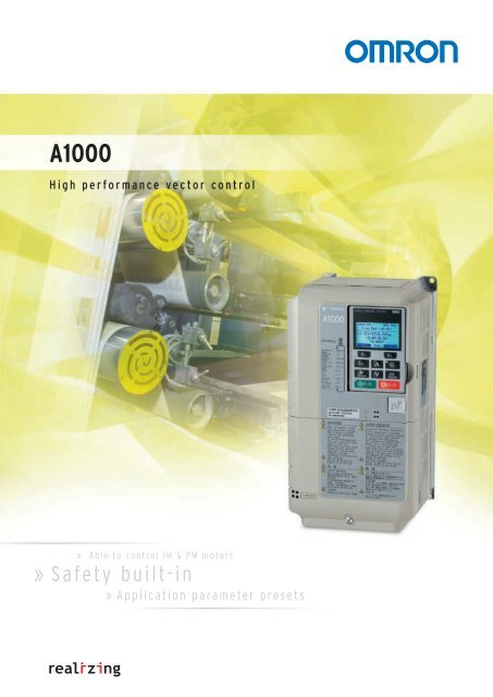
<strong>A1000</strong><br />
High performance vector control<br />
»<br />
Able to control IM & PM motors<br />
Safety built-in<br />
»<br />
Application parameter presets
High performance motor control…<br />
The <strong>A1000</strong> provides remarkable advantages<br />
through excellent motor drive performance,<br />
environmental benefits and energy savings,<br />
as well as many user orientated operational<br />
features. Moreover, the <strong>A1000</strong> offers advanced<br />
characteristics that are included as standard.<br />
In response to the needs of users, we have<br />
introduced next-generation product features<br />
to <strong>A1000</strong> vector control technology.<br />
Drive any kind of motor<br />
Induction motor Synchronous motor<br />
(SPM)<br />
Synchronous motor<br />
(IPM)<br />
In addition to built-in safety, IM & PM motor control,<br />
application parameter presets, USB copy unit, dual rating<br />
function and terminal board with parameter set-up, the<br />
following features will also ensure high performance<br />
motor control while saving costs and enabling you to<br />
work more efficiently:<br />
• Up to 315 kW<br />
• Open-loop IPM motor control<br />
• Powerful starting torque<br />
• High-performance current vector control<br />
• 10 years lifetime design<br />
• CE, UL and RoHS compliant<br />
… at your<br />
finger tips
Safety:<br />
According EN954-1 Category 3,<br />
EN61508 SIL2<br />
EN954-1<br />
Safety Category 3<br />
Compliance<br />
Safety controller<br />
Feedback loop<br />
EDM<br />
HC<br />
H1<br />
H2<br />
DM+<br />
DM-<br />
<strong>A1000</strong><br />
Application presets: Select your application and <strong>A1000</strong> will optimize<br />
parameter settings according to it.<br />
Crane (Traverse)<br />
Conveyor<br />
Fan<br />
More ...<br />
Crane (Hoist)<br />
Compressor<br />
Pump<br />
Setting Setting<br />
00 General-purpose<br />
01 Water Supply Pump<br />
02 Conveyor<br />
03 Exhaust Fan<br />
04 HVAC Fan<br />
05 Air Compressor<br />
06 Crane (Hoist)<br />
07 Crane (Traverse)<br />
Dual rating: A single parameter lets the user set the<br />
drive for Normal Duty or Heavy Duty<br />
Heavy Duty<br />
Normal Duty<br />
7.5 kW<br />
motor<br />
11 kW<br />
motor<br />
Applications<br />
150% inverter rated<br />
current for 1 minute<br />
120% inverter rated<br />
current for 1 minute<br />
Controller<br />
Parameters are programmed automatically<br />
A1-02 Control mode selection<br />
C1-01 Accel Time 1<br />
C1-02 Decel Time<br />
C6-01 ND / HD Selection<br />
Power<br />
supply<br />
Motor<br />
USB copy unit:<br />
With copy & paste parameter<br />
functionality<br />
Terminal board with parameter set-up:<br />
Integrated memory with all inverter’s parameter data for<br />
replacement jobs
CIMR-A<br />
<strong>A1000</strong><br />
High performance Vector Control<br />
• Current vector control, with or without PG<br />
• High starting torque (200% / 0.3 Hz, spd range 1:200 OLV),<br />
(200% at 0 r/min, spd range 1:1500 CLV)<br />
• Double rating ND 120%/1min and HD 150%/1 min<br />
• IM&PM motor control<br />
• Advanced Auto-Tuning for IM & PM Motors<br />
• Open Loop Control of PM Motors<br />
• Low-noise Low carrier technology<br />
• 10 years lifetime design<br />
• Screw-less terminals<br />
• Control Terminals with memory backup<br />
• 24 VDC control board power supply option<br />
• Fieldbus communications: Modbus, Profibus, CanOpen,<br />
DeviceNet, ML-II<br />
• Safety embedded: EN954-1 safety cat. 3, stop category 0,<br />
IEC EN 61508 SIL 2 and EN61800-5-1 with EDM<br />
• CE, UL, cUL and TUV<br />
Ratings<br />
• 200 V Class three-phase 0.4 to 110 kW<br />
• 400 V Class three-phase 0.4 to 315 kW<br />
System configuration<br />
Power<br />
Supply<br />
MCCB<br />
AC Reactor<br />
Filter<br />
<strong>A1000</strong><br />
Choke<br />
Motor<br />
Ground<br />
USB Copy Unit<br />
COM ERR<br />
Copy<br />
Verify<br />
Read<br />
LOCK<br />
JVOP-181<br />
YASKAWA<br />
Communications cable with PC<br />
RJ-45 / USB<br />
Adapter<br />
Remote Operator<br />
Extansion Cable<br />
24 VDC Control Board Power Supply<br />
Communication Option Board<br />
Feedback Speed Option Cards<br />
Braking Resistor<br />
DC Reactor<br />
USB Cable<br />
LCD Remote<br />
Operator<br />
CX-Drive<br />
CX-One<br />
4 Frequency inverters
Specifications<br />
Type designation<br />
200 V class<br />
Motor<br />
kW 1<br />
Output<br />
characteristics<br />
Power<br />
supply<br />
400 V class<br />
Three-phase: CIMR-A@2A 0004 0006 0010 0012 0021 0030 0040 0056 0069 0081 0110 0138 0169 0211 0250 0312 0360 0415<br />
For HD setting 0.40 0.75 1.5 2.2 4.0 5.5 7.5 11 15 18.5 22 30 37 45 55 75 90 110<br />
For ND setting 0.75 1.1 2.2 3.0 5.5 7.5 11 15 18.5 22 30 37 45 55 75 90 110 110<br />
Inverter capacity kVA at HD2 1.2 1.9 3 4.2 6.7 9.5 12.6 17.9 23 29 32 44 55 69 82 108 132 158<br />
Inverter capacity kVA at ND2 1.3 2.3 3.7 4.6 8 11.4 15.2 21 26 31 42 53 64 80 95 119 137 158<br />
Rated output current (A) at HD 3.2 4 5 4<br />
8 4<br />
11 4<br />
17.5 4 25 4<br />
33 4<br />
47 4<br />
60 4<br />
75 4<br />
85 4<br />
115 4 145 5 180 5 215 5 283 5 346 5 415 3<br />
Rated output current (A) at ND 3 3.5 6 9.6 12 21 30 40 56 69 81 110 138 169 211 250 312 360 415<br />
Max. output voltage Proportional to input voltage: 0..240 V<br />
Max. output frequency 400 Hz<br />
Rated input voltage and frequency 3-phase 200..240 V 50/60 Hz<br />
Allowable voltage fluctuation -15%..+10%<br />
Allowable frequency fluctuation +5%<br />
Input Current (A) at HD 6 2.9 5.8 7.5 11 18.9 28 37 52 68 80 82 111 136 164 200 271 324 394<br />
Input Current (A) at ND 6 3.9 7.3 10.8 13.9 24 37 52 68 80 96 111 136 164 200 271 324 394 471<br />
1. Based on a standard 4-pole motor for maximum applicable motor output:<br />
2. Rated Motor Capacity is calculated with a rated output voltage of 220 V:<br />
3. Carrier frequency is set to 2kHz. Current derating is required in order to raise the carrier frequency:<br />
4. Carrier frequency can be increased up to 8 kHz while keeping this current rating. Higher carrier frequency settings require derating:<br />
5. Carrier frequency can be increased up to 5 kHz while keeping this current rating. Higher carrier frequency settings require derating:<br />
6. Assumes operation at rated output current. Input current rating varies depending on the power supply transformer, input reactor,<br />
Wiring conditions, and power supply impedance:<br />
Motor<br />
kW 1<br />
Output<br />
characteristics<br />
Power<br />
supply<br />
CIMR AC4A0004 FAA Version<br />
AC Drive<br />
<strong>A1000</strong> series<br />
C: European standard<br />
specifications<br />
Voltage:<br />
2: Three-phase 200 VAC<br />
4: Three-phase 400 VAC<br />
A: Standard specs<br />
Coating specs:<br />
A: Standard<br />
Enclosure, Fin:<br />
A: IP00<br />
F: IP20 / Nema 1<br />
Rated output Current<br />
Normal Duty<br />
0004: 3.5 [A]<br />
~<br />
0675: 675 [A]<br />
Three-phase: CIMR-A@4A 0002 0004 0005 0007 0009 0011 0018 0023 0031 0038 0044 0058<br />
For HD setting 0.4 0.75 1.5 2.2 3.0 4.0 5.5 7.5 11 15 18.5 22<br />
For ND setting 0.75 1.5 2.2 3.0 4.0 5.5 7.5 11 15 18.5 22 30<br />
Inverter capacity kVA at HD 2 1.4 2.6 3.7 4.2 5.5 7 11.3 13.7 18.3 24 30 34<br />
Inverter capacity kVA at ND 2 1.6 3.1 4.1 5.3 6.7 8.5 13.3 17.5 24 29 34 44<br />
Rated output current (A) at HD 1.8 4 3.4 4 4.8 4 5.5 4 7.2 4 9.2 4 14.8 4 18 4 24 4 31 4 39 4 45 4<br />
Rated output current (A) at ND 3 2.1 4.1 5.4 6.9 8.8 11.1 17.5 23 31 38 44 58<br />
Max. output voltage 380..480V (proportional to input voltage)<br />
Max. output frequency 400 Hz<br />
Rated input voltage and frequency 3-phase 380..480 VAC, 50/60 Hz<br />
Allowable voltage fluctuation -15%..+10%<br />
Allowable frequency fluctuation +5%<br />
Input Current (A) at HD 6 1.8 3.2 4.4 6 8.2 10.4 15 20 29 39 44 49<br />
Input Current (A) at ND 6 2.1 4.3 5.9 8.1 9.4 14 20 24 38 44 52 58<br />
<strong>A1000</strong> 5
Specifications<br />
Motor<br />
kW 1<br />
Output<br />
characteristics<br />
Power<br />
supply<br />
Three-phase: CIMR-A@4A 0072 0088 0103 0139 0165 0208 0250 0296 0362 0414 0515 0675<br />
For HD setting 30 37 45 55 75 90 110 132 160 185 220 315<br />
For ND setting 37 45 55 75 90 110 132 160 185 220 250 355<br />
Inverter capacity kVA at HD 2 48 57 69 85 114 137 165 198 232 282 343 461<br />
Inverter capacity kVA at ND 2 55 67 78 106 126 159 191 226 276 316 392 514<br />
Rated output current (A) at HD 60 4<br />
75 4<br />
91 4<br />
112 5<br />
150 5<br />
180 5<br />
216 5<br />
260 5 3<br />
304 370 450 605<br />
Rated output current (A) at ND 3 72 88 103 139 165 208 250 296 362 414 515 675<br />
Max. output voltage<br />
380..480V (proportional to input voltage)<br />
Max. output frequency<br />
400 Hz<br />
Rated input voltage and frequency 3-phase 380..480 VAC, 50/60 Hz<br />
Allowable voltage fluctuation<br />
-15%..+10%<br />
Allowable frequency fluctuation<br />
+5%<br />
Input Current (A) at HD6 58 71 86 105 142 170 207 248 300 346 410 584<br />
Input Current (A) at ND 6 71 86 105 142 170 207 248 300 346 410 465 657<br />
1. Based on a standard 4-pole motor for maximum applicable motor output:<br />
2. Rated Motor Capacity is calculated with a rated output voltage of 440 V:<br />
3. Carrier frequency is set to 2kHz. Current derating is required in order to raise the carrier frequency:<br />
4. Carrier frequency can be increased up to 8 kHz while keeping this current rating. Higher carrier frequency settings require derating:<br />
5. Carrier frequency can be increased up to 5 kHz while keeping this current rating. Higher carrier frequency settings require derating:<br />
6. Assumes operation at rated output current. Input current rating varies depending on the power supply transformer, input reactor,<br />
Wiring conditions, and power supply impedance:<br />
Commom specifications<br />
Control functions<br />
Functionality<br />
Protection functions<br />
Model number<br />
CIMR-A<br />
Specifications<br />
Control methods<br />
Sine wave PWM (V/f control, V/f control with PG, Open loop vector control, Closed loop vector control, Open loop vector<br />
control for PM, Closed loop vector control for PM, Advanced Open Loop Vector Control for PM)<br />
Output frequency range 0.01..400 Hz<br />
Frequency tolerance<br />
Digital set value: ±0.01% of the max. output frequency (-10..+40 ºC)<br />
Analogue set value: ±0.1% of the max. output frequency (25 ±10 ºC)<br />
Resolution of frequency set value<br />
Digital set value: 0.01 Hz<br />
Analogue set value: 0.03 Hz / 60 Hz (11 bit)<br />
Resolution of output frequency 0.001 Hz<br />
Frequency set value<br />
-10..+10 V (20 kΩ),0..10 V (20 kΩ), 4..20 mA (250 Ω),<br />
Pulse train input, frequency setting value (selectable)<br />
150%/3Hz (V/f control, V/f control with PG), 200%/0.3Hz*<br />
Starting Torque<br />
1 (Open loop vector control), 200%/ 0 r/min* 1 (Closed loop vector<br />
control, Closed loop vector control for PM, Advanced Open Loop Vector Control for PM), 100% / 5% speed (Open<br />
loop vector control for PM),<br />
Speed Control Range<br />
1:1500 (Closed loop vector control, Closed loop vector control for PM), 1:200 (Open loop vector control), 1:40 (V/f control,<br />
V/f control with PG), 1:20 (Open Loop Vector Control for PM), 1:100 (Advanced Open Loop Vector Control for PM)<br />
Speed Control Accuracy ±0.2% in Open loop vector control (25 ±10 ºC) * 2 , 0.02% in Closed loop vector control (25 ±10 ºC)<br />
Speed Response<br />
10 Hz in Open loop vector control (25 ±10 ºC), 50Hz in Closed loop Vector Control (25 ±10 ºC), )(excludes temperature<br />
fluctuation when performing Rotational Auto-Tuning)<br />
Torque Limit All Vector Control allows seperate settings in four quadrants<br />
Accel/Decel Time 0.00 to 6000.0 s (4 selectable combinations of independent acceleration and deceleration settings)<br />
Drives of 200/400 V 30 kW or less have a built-in braking transistor.<br />
1. Short-time decel torque*<br />
Braking torque<br />
3 , over 100% for 0.4/0.75 kW motors, over 50% for 1.5 kW motors, and over 20% for 2.2 kW<br />
and above motors (over excitation braking/High-Slip Braking approx. 40%)<br />
2. Continuous regen, torque approx. 20% (approx. 125% with dynamic braking resistor option* 4 , 10% ED,10 s, internal<br />
braking transistor)<br />
V/f Characteristics User-selected programs and V/f preset pattens possible<br />
Torque Control, Droop control, Speed/torque control switching, Feedforward control, Zero-servo control, Momentary<br />
power loss ride-thru, Speed search, Overtorque detection, Torque Limit, 17-step speed (max), Accel/Decel time switch<br />
S-curve Accel/Decel, 3-wire sequence, Auto-tuning (rotational, stationary), Online Tuning, Dwell Cooling fan on/off<br />
Main Control Functions<br />
switch, slip compensation, Torque compensation, Frequency Jump, Upper/lower limits for frequency, DC injection braking<br />
at start and stop, Over excitation braking, High Slip braking, PID control (with sleep function), Energy saving control,<br />
MEMOBUS comm. (RS-485/422 max. 115.2kbps), Fault restart, Application presets, Removable terminal block with parameter<br />
backup function...<br />
Motor protection Motor overheat protection based on output current<br />
Momentary overcurrent<br />
Protection<br />
Drive stops when ouput current exceeds 200% of Heavy Duty Rating<br />
Overload Protection Drive stops after 60 s at 150% of rated output current (Heavy Duty Rating)* 5<br />
Overvoltage Protection 200 V class: Stops when DC bus exceeds approx. 410 V, 400 V class: Stops when DC bus exceeds approx. 820V<br />
Undervoltage Protection 200 V class: Stops when DC bus exceeds approx. 190 V, 400 V class: Stops when DC bus exceeds approx. 380V<br />
Momentary power loss Ride-Thru<br />
Immediately stop after 15 ms or longer power loss (default),<br />
Continuous operation during power loss than 2 s (srandard)* 6<br />
Heatsink Overheat Protection Protected by thermister<br />
Braking Resistance Overheat<br />
Protection<br />
Overheat sensor for braking resistor (optional)<br />
Stall prevention Stall prevention during acceleration/deceleration and constant speed operation<br />
Ground fault Protected by electronic circuit* 7<br />
Power charge indication Charge LED remains lit until DC bus has fallen below approx. 50 V.<br />
6 Frequency inverters
Ambient conditions<br />
Area of Use Indoor (no corrosive gas, dust, etc.)<br />
Ambient Temperature -10ºC..+50ºC(open chassis) up to 60ºC with output current derating, -10ºC..+40ºC (NEMA Type 1)<br />
Ambient humidity 95% RH or less (without condensation)<br />
Storage temperature -20ºC..+60ºC (short-term temperature during transportation)<br />
Altitude Up to 1000 meters (output derating of 1% per 100 m above 1000 m, max. 3000 m)<br />
Vibration / Shock<br />
10 Hz to 20 Hz, 9.8 m/s2 max. 20 Hz to 55Hz, 5.9 m/s2 (200 V: 45kW or more, 400 V: 55kW or more) or<br />
2.0 m/s 2 max. (200 V: 55 kW or less, 400 V: 75 kW or less)<br />
Safety Standard EN954-1 safe category 3 stop category 0; EN ISO 13849-1; IEC EN 61508 SIL2<br />
Protection Design IP00 open-chassis, IP20, NEMA Type 1 enclosure<br />
1. Requires a drive with recommended capacity.<br />
2. Speed control accuracy may vary slightly depending on installation conditions or motor used.<br />
3. Momentary average deceleration torque refers to the deceleration torque form 60 Hz down to 0 Hz. This may vary depending on the motor.<br />
4. If L3-04 is enabled when using a braking resistor or braking resistor unit, the motor may not stop in the specified deceleration time.<br />
5. Overload protection may be triggered when operating with 150% of the rated output current, if the output frequency is less than 6 Hz.<br />
6. Varies in accordance with the drive capacity and load. Drives with a capacity of smaller than 11 kW in the 200 V (model CIMR- AA0056 or 400 V (model<br />
CIMR- AA0031) require a seperate Momentary Power Loss Unit to continue operating.<br />
7. Protection may not be provided under the following conditions as the motor windings are grounded internally during run: #Low resistance to ground from<br />
the motor cable or terminal block. #Drive already has a short-circuit when the power is turned on.<br />
Dimensions<br />
Open-Chassis [IP00]<br />
Max 10 W<br />
Voltage class<br />
Three-phase<br />
200 V<br />
Three-phase<br />
400 V<br />
W1 4-d<br />
H1<br />
H<br />
H2<br />
Max 10<br />
Figure 1<br />
D<br />
t2<br />
t1<br />
D1<br />
Max 7.7<br />
Max. applicable<br />
Dimensions in mm<br />
motor output kW Inverter model<br />
CIMR-A@<br />
Figure<br />
ND HD W H D W1 H1 H2 D1 t1 t2 d<br />
30 22 0110<br />
250 400<br />
195 385<br />
21<br />
258<br />
100<br />
37 30 0138 275 450 220 435 25<br />
7.5<br />
2.3 2.3 M6<br />
45 37 0169<br />
37<br />
325 550 283 260 535 110<br />
55 45 0211 38<br />
1<br />
75 55 0250<br />
76<br />
450 705 330 325 680 12.5<br />
3.2 3.2 M10<br />
90 75 0312 80<br />
130<br />
110 90 0360<br />
98<br />
500 800 350 370 773 13 4.5 4.5 M12<br />
110 110 0415 99<br />
30 22 0058<br />
250 400<br />
195 385<br />
21<br />
100<br />
2.3<br />
37 30 0072 275 450 220 435 25<br />
258<br />
45 37 0088<br />
36<br />
510<br />
495 7.5 105 2.3 3.2 M6<br />
55 45 0103 36<br />
325<br />
260<br />
75 55 0139<br />
41<br />
1<br />
550 283 535 110 2.3<br />
90 75 0165 42<br />
110 90 0208 450 705 330 325 680 12.5<br />
W1<br />
132 110 0250<br />
96<br />
130<br />
160 132 0296 800 350<br />
773<br />
102<br />
500<br />
370<br />
13<br />
185 160 0362 107<br />
4.5 4.5 M12<br />
220 185 0414 2 950<br />
923 135 125<br />
<strong>A1000</strong> 7<br />
4-d<br />
H1<br />
H2<br />
H<br />
W Max 7.7<br />
Figure 2<br />
Weight<br />
(kg)<br />
3.2 3.2 M10 79<br />
250 220 0515<br />
370<br />
216<br />
3 670 1140 440 1110 15 150<br />
355 315 0675 221<br />
D<br />
t2<br />
D1<br />
t1<br />
Max 6<br />
W1<br />
W<br />
4-d<br />
H1<br />
H<br />
H2<br />
Max 6<br />
Figure 3<br />
D<br />
t2<br />
D1<br />
t1
Enclosed Panel [NEMA Type1]<br />
Voltage class<br />
Three-phase<br />
200 V<br />
Three-phase<br />
400 V<br />
Schaffner Flat Filters<br />
200 V<br />
400 V<br />
Max. applicable<br />
motor output kW<br />
Dimensions in mm<br />
Inverter model<br />
Figure<br />
CIMR-A@<br />
ND HD W H D W1 H1 H2 D1 t1 t2 d<br />
0.75 0.4 0004<br />
1.1 0.75 0006 3.1<br />
147<br />
38<br />
2.2 1.5 0010 3.2<br />
3 2.2 0012 140 260<br />
122 248 6<br />
3.2<br />
M5<br />
5.5 4.0 0021 1<br />
164<br />
3.5<br />
5 -<br />
7.5 5.5 0030<br />
55<br />
4.0<br />
167<br />
11 7.5 0040 4.0<br />
15 11 0056 180 300 187 160 284<br />
18.5 15 0069<br />
350<br />
8<br />
8.7<br />
220<br />
197 192 335 78 M6<br />
22 18.5 0081 2 365 9.7<br />
0.75 0.4 0002<br />
8 Frequency inverters<br />
Weight<br />
(kg)<br />
3.1<br />
75 5.6<br />
1.5 0.75 0004 147<br />
38<br />
3.2<br />
2.2 1.5 0005 3.2<br />
3 2.2 0007<br />
3.4<br />
140 260<br />
122 248 6<br />
4.0 3 0009 164<br />
3.5<br />
M5<br />
5.5 4.0 0011 1<br />
5 -<br />
3.5<br />
55<br />
7.5 5.5 0018<br />
3.9<br />
11 7.5 0023 167<br />
3.9<br />
15 11 0031<br />
5.4<br />
180 300 160 284<br />
18.5 15 0038 187 8 75 5.7<br />
22 18.5 0044 220 350 197 192 335 78 M6 8.3<br />
Flat Filters<br />
W1 4-d 1.5<br />
W<br />
3G3RV-PFI2035-SE<br />
Fig Dimensions Weight<br />
KG<br />
A B C D E F G H I L<br />
330 141 46 281 313 115 5.5 M5 23 M5 1.4<br />
3G3RV-PFI2060-SE 1 355 206 60 302 336 175 6.5 M6 30 M6 3<br />
3G3RV-PFI2100-SE 408 236 80 355 390 205 6.5 M6 40 M6 4.9<br />
3G3RV-PFI3010-SE<br />
330 141 46 281 313 115 5.5 M4 23 M5 1.2<br />
3G3RV-PFI3018-SE 330 141 46 281 313 115 5.5 M4 23 M5 1.3<br />
1<br />
3G3RV-PFI3035-SE 355 206 50 302 336 175 6.5 M5 25 M6 2.2<br />
3G3RV-PFI3060-SE 408 236 65 355 390 205 6.5 M6 32.5 M6 4<br />
3G3RV-PFI3410-SE<br />
H2<br />
H1<br />
5 H<br />
t1<br />
D1<br />
D<br />
W1<br />
W<br />
D<br />
386 115 260 - 120 235 12.0 M12 - - 8.5<br />
3G3RV-PFI3600-SE 2 386 135 260 - 120 235 12.0 M12 - - 11.0<br />
3G3RV-PFI3800-SE 564 160 300 - 210 275 9.0 M12 - - 31.0<br />
H1<br />
H3<br />
H2<br />
Figure 1 Figure 2<br />
Figure 1<br />
4-d<br />
1.5<br />
H<br />
8<br />
C<br />
F<br />
E<br />
E<br />
Figure 2<br />
t1<br />
D1<br />
B<br />
A<br />
3.2
Bookform Filters<br />
200 V<br />
400 V<br />
Remote LCD operator<br />
Chokes<br />
Bookform Filters<br />
Dimensions Weight<br />
KG<br />
A B C D E F G H<br />
3G3RV-PFI2130-SE 310 180 90 280 295 65 6.5 M10 4.3<br />
3G3RV-PFI2160-SE 380 170 120 350 365 102 6.5 M10 6.0<br />
3G3RV-PFI2200-SE 518 240 130 480 498 90 8.2 M10 11.0<br />
3G3RV-PFI3070-SE 329 185 80 300 314 55 6.5 M6 3.4<br />
3G3RV-PFI3130-SE 310 180 90 280 295 65 6.5 M10 4.7<br />
3G3RV-PFI3170-SE 380 170 120 350 365 102 6.5 M10 6.0<br />
3G3RV-PFI3250-SE 610 240 130 480 498 90 8.3 M10 11.7<br />
3G3RV-PFI3410-SE 386 115 260 - 120 235 12.0 M12 8.5<br />
3G3RV-PFI3600-SE 386 135 260 - 120 235 12.0 M12 11.0<br />
3G3RV-PFI3800-SE 564 160 300 - 210 275 9.0 M12 31.0<br />
Description D<br />
diameter<br />
Motor<br />
KW<br />
Dimensions Weight<br />
Kg<br />
L W H X Y m<br />
<strong>A1000</strong>-FEV2102-RE 21 < 2.2 85 22 46 70 - 5 0.1<br />
<strong>A1000</strong>-FEV2515-RE 25 < 15 105 25 62 90 - 5 0.2<br />
<strong>A1000</strong>-FEV5045-RE 50 < 45 150 50 110 125 30 5 0.7<br />
<strong>A1000</strong>-FEV6045-RE 60 > 45 200 65 170 180 45 6 1.7<br />
90 (3.54)<br />
D<br />
A<br />
E<br />
12.2<br />
(0.48)<br />
60 (2.36) 7.9<br />
1.6 (0.06)<br />
(0.31)<br />
<strong>A1000</strong> 9<br />
<br />
H<br />
G<br />
F<br />
15<br />
(0.59)<br />
minimum 50 (1.96) Unit : mm (in)<br />
C<br />
B<br />
Installation holes<br />
(2-M3 screws, depth 5 (0.19))<br />
44 (1.73)<br />
W Y<br />
H<br />
78 (3.07)<br />
X<br />
L<br />
Ø d<br />
Ø m
Braking Unit<br />
Resistor Dimensions<br />
<strong>A1000</strong>-REJ0K15___ <strong>A1000</strong>-REJ0K10___<br />
Braking Resistor Unit<br />
Voltage Model<br />
LKEB-_<br />
220 V<br />
Class<br />
400 V<br />
Class<br />
11.5<br />
Model CDBR-2015 B, -2022 B, -4030B, -4045 B Model CDBR-2110 B<br />
30 or<br />
more<br />
4-M4 MTG Holes 72<br />
38 38<br />
128<br />
140<br />
3-lead Wire Inlet<br />
(20 Dia. Rubber Bush)<br />
168<br />
20<br />
45<br />
138<br />
150<br />
30 or<br />
more<br />
Mass 1.8 K<br />
114.5<br />
138.5<br />
Dimensions in mm Mass<br />
kg<br />
A B C D MTG Screw<br />
21P5<br />
22P2 130 350 75 335 M5 x 3<br />
4.5<br />
23P7 5.0<br />
25P5<br />
27P5<br />
250 350 200 335 M6 x 4<br />
7.5<br />
8.5<br />
2011 266 543 246 340 M8 x 4 10<br />
2015 356 543 336 340 M8 x 4 15<br />
2018<br />
2022<br />
446 543 426 340 M8 x 4 19<br />
41P5<br />
42P2<br />
130 350 75 335 M5 x 4 4.5<br />
43P7 130 350 75 335 M5 x 4 5.0<br />
45P5<br />
47P5<br />
250 350 200 335 M6 x 4<br />
7.5<br />
8.5<br />
4011<br />
4015<br />
350 412 330 325 M6 x 4<br />
16<br />
18<br />
4018<br />
4022<br />
446 543 426 340 M8 x 4 19<br />
4030 356 956 336 740 M8 x 4 25<br />
4037 446 956 426 740 M8 x 4 33<br />
4045 446 956 426 740 M8 x 4 33<br />
66.5<br />
182<br />
100 or more<br />
100 or more<br />
9 36.5<br />
370<br />
355<br />
317<br />
70<br />
30<br />
or<br />
more<br />
156.5<br />
118.5<br />
Model CDBR-4220 B<br />
210<br />
Main Circuit<br />
Terminal<br />
M6<br />
50<br />
210<br />
250<br />
30<br />
or<br />
more<br />
Mass 12 Kg<br />
Mass 8.5 Kg<br />
10 Frequency inverters<br />
4-M6<br />
MTG Holes<br />
104<br />
111<br />
156<br />
200<br />
100 or more 100 or more<br />
12<br />
36.5<br />
370<br />
350<br />
Lead Wire Inlet<br />
(28 Dia. Rubber Bush)<br />
2-lead Wire Inlet<br />
(35 Dia. Rubber Bush)<br />
27<br />
317<br />
73<br />
30<br />
or<br />
more<br />
36<br />
<br />
C<br />
100<br />
59<br />
140<br />
Main Circuit<br />
Terminal<br />
M6<br />
50<br />
140<br />
180<br />
30<br />
or<br />
more<br />
MTG Screw<br />
C<br />
4-M6<br />
MTG Holes<br />
MTG Screw<br />
D<br />
30 or more A<br />
30 or more<br />
B<br />
104<br />
111<br />
156<br />
200<br />
105<br />
D<br />
B<br />
50 or more A<br />
50 or more<br />
150<br />
100 or less 100 or less<br />
Lead Wire Inlet<br />
(28 Dia. Rubber Bush)<br />
2-lead Wire Inlet<br />
(35 Dia. Rubber Bush)<br />
260<br />
150 or more 150 or more<br />
200 or more<br />
200 or more
Installation<br />
Standard connections<br />
Three-phase<br />
power supply<br />
200 to 400 V<br />
50/60 Hz<br />
R/L1<br />
S/L2<br />
T/L3<br />
Main circuit<br />
Multi-function<br />
analog/ pulse<br />
train inputs<br />
Main<br />
Switch<br />
Multi-function<br />
digtial inputs<br />
(default setting)<br />
Safety<br />
switch<br />
S2<br />
S1<br />
Open<br />
Safety relay /<br />
controller<br />
Terminals -, +1, +2, B1, B2 are<br />
for connection options. Never<br />
connect power supply lines to<br />
these terminals<br />
Fuse<br />
Forward Run / Stop<br />
Reverse Run / Stop<br />
External fault<br />
Fault reset<br />
Multi-speed step 1<br />
Multi-speed step 2<br />
Jog speed<br />
External Baseblock<br />
Sink / Source mode<br />
selection wire link<br />
(default: Sink)<br />
2 kΩ<br />
MEMOBUS/Modbus<br />
comm. RS485/422<br />
max. 115.2 kBps<br />
EMC<br />
Filter<br />
DC reactor<br />
(option)<br />
U X<br />
Jumper<br />
+ 2 + 1 B1 B2<br />
Main Circuit<br />
Thermal relay<br />
(option)<br />
Braking resistor<br />
(option)<br />
Terminal Name Function (signal level)<br />
R/L1, S/L2, T/L3 Main circuit power supply input Used to connect line power to the drive.<br />
U/T1, V/T2, W/T3 Inverter output Used to connect the motor<br />
S1<br />
S2<br />
S3<br />
S4<br />
S5<br />
S6<br />
S7<br />
A2<br />
Safe Disable inputs H1<br />
Wire<br />
jumper<br />
R/L1<br />
S/L2<br />
T/L3<br />
A3 Analog Input 3 / PTC Input (Aux. frequency<br />
reference)<br />
AC -10 to +10 Vdc (20 kΩ)<br />
0 V<br />
−V Power supply, -10.5 Vdc, max. 20 mA<br />
Termination resistor<br />
(120 Ω, 1/2 W)<br />
DIP<br />
Switch S2<br />
R +<br />
R<br />
S +<br />
S<br />
IG<br />
H2<br />
HC<br />
Control Circuit<br />
<strong>A1000</strong><br />
Option card connectors<br />
CN5-C<br />
CN5-B<br />
CN5-A<br />
Terminal board<br />
jumpers and switches<br />
DIP Switch S1<br />
V I<br />
A2 Volt/Curr. Sel<br />
+V Power supply +10.5 Vdc, max. 20 mA<br />
A1 Analog Input 1 (Frequency Reference Bias)<br />
-10 to +10 Vdc (20 kΩ)<br />
Analog Input 2 (Frequency Reference Bias)<br />
-10 to +10 Vdc (20 kΩ)<br />
0 or 4 to 20 mA (250 Ω)<br />
DIP Switch S2<br />
Off On<br />
Term. Res. On/Off<br />
S8<br />
Jumper S3<br />
H1, H2<br />
Sink/Source Sel.<br />
SN<br />
PTC DIP Switch S4<br />
SC<br />
AI<br />
A3 Analog/PTC<br />
Input Sel<br />
SP<br />
Jumper S5<br />
+24 V<br />
V<br />
AM/FM Volt./Curr.<br />
I Selection<br />
FM AM<br />
RP<br />
Shield ground terminal<br />
Pulse Train Input (max 32 kHz)<br />
EDM (Safety Electronic Device Monitor)<br />
DM +<br />
B1, B2 Braking resistor connection Available for connecting a braking resistor or the braking resistor unit option.<br />
+2, +1 DC reactor connection Remove the short bar between +2 and +1 when connecting DC reactor (option)<br />
+1, – DC power supply input For power supply input (+1: positive electrode; – : negative electrode)*<br />
+3 Braking Unit Connection for Braking Unit between terminals +3 and –<br />
Grounding For grounding (grounding should conform to the local grounding code.)<br />
<strong>A1000</strong> 11<br />
U/T1<br />
V/T2<br />
W/T3<br />
0 V<br />
0 V<br />
MA<br />
MB<br />
MC<br />
M1<br />
M2<br />
M3<br />
M4<br />
M5<br />
M6<br />
MP<br />
AC<br />
FM<br />
AM<br />
AC<br />
E (G)<br />
DM<br />
Ground<br />
Shielded<br />
Cable<br />
Fault relay output<br />
250 Vac, max. 1 A<br />
30 Vdc, max 1 A<br />
(min. 5 Vdc, 10 mA)<br />
+<br />
FM<br />
U<br />
V<br />
W<br />
M<br />
Multi-function relay output (During Run)<br />
250 Vac, max. 1 A<br />
30 Vdc, max 1 A<br />
(min. 5 Vdc, 10 mA)<br />
Multi-function relay output (Zero Speed)<br />
250 Vac, max. 1 A<br />
30 Vdc, max 1 A<br />
(min. 5 Vdc, 10 mA)<br />
Multi-function pulse train output<br />
(Output frequency)<br />
0 to 32 kHz (2.2 kΩ)<br />
Motor<br />
Multi-function relay output (Speed Agree 1)<br />
250 Vac, max. 1 A<br />
30 Vdc, max 1 A<br />
(min. 5 Vdc, 10 mA)<br />
+<br />
AM<br />
Multi-function analog output 1<br />
(Output frequency)<br />
-10 to +10 Vdc (2mA) or 4 to 20 mA<br />
Multi-function analog output 2<br />
(Output current)<br />
-10 to +10 Vdc (2mA) or 4 to 20 mA<br />
shielded line<br />
twisted-pair shielded line<br />
control circuit terminal<br />
main circuit terminal
Control Circuit<br />
Type No. Signal name Function Signal level<br />
Digital input signals<br />
Analog input signals<br />
Safety Input<br />
Safety<br />
monitor<br />
output<br />
Digital output signals<br />
Analog output<br />
signals<br />
PulseI/O<br />
RS-485/422<br />
S1 Multi-function input selection 1 Factory setting: runs when CLOSED, stops when OPEN.<br />
S2 Multi-function input selection 2 Factory setting: runs when CLOSED, stops when OPEN.<br />
S3 Multi-function input selection 3 Factory setting: External Fault (N.O.)<br />
S4 Multi-function input selection 4 Factory setting: Fault reset<br />
S5 Multi-function input selection 5 Factory setting: Multi-step speed cmd 1<br />
S6 Multi-function input selection 6 Factory setting: Multi-step speed cmd 2<br />
S7 Multi-function input selection 7 Factory setting: Jog Frequency<br />
S8 Multi-function input selection 8 Factory setting: Closed gives external baseblock<br />
SC<br />
Multi-function input selection<br />
Common<br />
Common for control signal<br />
+V Power Supply for Frequency Setting +10.5 V (allowable max current 20 mA)<br />
–V Power Supply for Frequency Setting –10.5 V (allowable max current 20 mA)<br />
A1 Multi-function analogue input 1 Main Frequency Reference -10 to +10 VDC, 0 to +10 VDC (20 kΩ)<br />
A2 Multi-function analogue input 2<br />
Voltage input or current input<br />
-10 to +10 VDC, 0 to +10 VDC (20 kΩ)<br />
4 to 20 mA (250 Ω)<br />
A3 Multi-function analogue input 3 –10 to +10 V, 0 to +10 V (20 kΩ)<br />
AC Frequency reference common 0V<br />
HC Safety Input Common +24 V (max allowable current 10 mA)<br />
H1 Safety Input 1<br />
H2 Safety Input 2<br />
DM+ Safety monitor output<br />
DM– Safety monitor output common<br />
MA NO contact output<br />
Open: Stop Closed: Normal Operation<br />
24 VDC, 8 mA<br />
photocoupler<br />
insulation<br />
Photocoupler 24 V<br />
DC, 8 mA<br />
Open: Safety inputs 1 and 2 are open 48 Vdc, 50mA or less<br />
MB NC Output<br />
Factory setting: "fault" Contact capacity<br />
250 VAC,<br />
MC Relay Output common<br />
1 A or less<br />
30 VDC, 1 A<br />
M1<br />
or less<br />
Multi-function contact output (N.O ) Factory setting Closed: During run<br />
M2<br />
P1 Photocoupler output 1 Factory setting: Zero speed<br />
P2 Photocoupler output 2 Factory setting: Frequency Agree<br />
PC Photocoupler output common 0V<br />
FM Multi-function analog monitor (1) Factory setting: Output frequency<br />
AM Multi-function analog monitor (2) Factory setting: "Current monitor, 5 V/drive rated current<br />
AC Analog monitor common 0V<br />
RP Main Speed Cmd Pulse Train Input 32 kHz max. (3 kΩ)<br />
MP Pulse Train Output Factory setting: Frequency reference input (H6-01=0) 0 to 33 kHz (2.2 kΩ)<br />
R+ Communication input (+)<br />
R– Communication input (–)<br />
S+ Communication output (+)<br />
S– Communication output (–)<br />
For MEMOBUS communication<br />
operation by RS-485 or RS-422 communication is available.<br />
Photocoupler output:<br />
+48 VDC, 50 mA or<br />
less<br />
–10 to 10 V ±5%,<br />
(2 mA or less)<br />
0 to 10 V<br />
4 - 20 mA<br />
RS-485/422<br />
MEMOBUS<br />
protocol<br />
12 Frequency inverters
Inverter heat loss<br />
Three-phase 200 V class<br />
Model Number<br />
CIMR-A<br />
Rated Amps (A)<br />
Three-phase 400 V class<br />
Heatsink Loss<br />
(W)<br />
Heavy Duty Normal Duty<br />
Interior Unit<br />
Loss (W)<br />
Total Loss (W) Rated Amps (A)<br />
Heatsink Loss<br />
(W)<br />
Interior Unit<br />
Loss (W)<br />
Total Loss (W)<br />
2A0004 3.2 14.8 44 59 3.5 18.4 47 66<br />
2A0006 5.0 24 48 72 6.0 31 51 82<br />
2A0010 8.0 43 52 95 9.6 57 58 115<br />
2A0012 11.0 64 58 122 12.0 77 64 141<br />
2A0021 17.5 101 67 168 21 138 83 222<br />
2A0030 25 194 92 287 30 262 117 379<br />
2A0040 33 214 105 319 40 293 145 437<br />
2A0056 47 280 130 410 56 371 175 546<br />
2A0069 60 395 163 558 69 491 205 696<br />
2A0081 75 460 221 681 81 527 257 785<br />
2A0110 85 510 211 721 110 719 286 1005<br />
2A0138 115 662 250 912 138 842 312 1154<br />
2A0169 145 816 306 1122 169 1014 380 1394<br />
2A0211 180 976 378 1354 211 1218 473 1691<br />
2A0250 215 1514 466 1980 250 1764 594 2358<br />
2A0312 283 1936 588 2524 312 2020 665 2686<br />
2A0360 346 2564 783 3347 360 2698 894 3591<br />
2A0415 415 2672 954 3626 415 2672 954 3626<br />
Model Number<br />
CIMR-A<br />
Rated Amps (A)<br />
Heatsink Loss<br />
(W)<br />
Heavy Duty Normal Duty<br />
Interior Unit<br />
Loss (W)<br />
Total Loss (W) Rated Amps (A)<br />
Heatsink Loss<br />
(W)<br />
Interior Unit<br />
Loss (W)<br />
Total Loss (W)<br />
4A0002 1.8 15.9 45 61 2.1 20 48 68<br />
4A0004 3.4 25 46 70 4.1 32 49 81<br />
4A0005 4.8 37 49 87 5.4 45 53 97<br />
4A0007 5.5 48 53 101 6.9 62 59 121<br />
4A0009 7.2 53 55 108 8.8 66 60 126<br />
4A0011 9.2 69 61 130 11.1 89 73 162<br />
4A0018 14.8 135 86 221 17.5 177 108 285<br />
4A0023 18.0 150 97 247 23 216 138 354<br />
4A0031 24 208 115 323 31 295 161 455<br />
4A0038 31 263 141 403 38 340 182 521<br />
4A0044 39 330 179 509 44 390 209 599<br />
4A0058 45 349 170 518 58 471 215 686<br />
4A0072 60 484 217 701 72 605 265 870<br />
4A0088 75 563 254 817 88 684 308 993<br />
4A0103 91 723 299 1022 103 848 357 1205<br />
4A0139 112 908 416 1325 139 1215 534 1749<br />
4A0165 150 1340 580 1920 165 1557 668 2224<br />
4A0208 180 1771 541 2313 208 1800 607 2408<br />
4A0250 216 2360 715 3075 250 2379 803 3182<br />
4A0296 260 2391 787 3178 296 2448 905 3353<br />
4A0362 304 3075 985 4060 362 3168 1130 4298<br />
4A0414 370 3578 1164 4742 414 3443 1295 4738<br />
4A0515 450 3972 1386 5358 515 4850 1668 6518<br />
4A0675 605 4191 1685 5875 675 4861 2037 6898<br />
<strong>A1000</strong> 13
Connections for braking unit and braking resistor<br />
AC reactor<br />
200 V class 400 V class<br />
Max. applicable<br />
Current value<br />
Inductance<br />
Max. applicable<br />
Current value<br />
Inductance<br />
motor output kW<br />
A<br />
mH<br />
motor output kW<br />
A<br />
mH<br />
0.4 2.5 4.2 0.4 1.3 18<br />
0.75 5 2.1 0.75 2.5 8.4<br />
1.5 10 1.1 1.5 5 4.2<br />
2.2 15 0.71 2.2 7.5 3.6<br />
4.0 20 0.53 4.0 10 2.2<br />
5.5 30 0.35 5.5 15 1.42<br />
7.5 40 0.265 7.5 20 1.06<br />
11 60 0.18 11 30 0.7<br />
15 80 0.13 15 40 0.53<br />
18.5 90 0.12 18.5 50 0.42<br />
22 120 0.09 22 60 0.36<br />
30 160 0.07 30 80 0.28<br />
37 200 0.05 37 90 0.24<br />
45 240 0.044 45 120 0.18<br />
55 280 0.039 55 150 0.15<br />
75 360 0.026 75 200 0.11<br />
90 500 0.02 90/110 250 0.09<br />
110 600 0.02 132/160 330 0.06<br />
- 160/185/220 490 0.04<br />
315 660 0.03<br />
DC reactor<br />
Power<br />
supply<br />
THRX OFF<br />
SA<br />
Thermal relay switch for<br />
external braking resistor<br />
MC<br />
ON<br />
MCCB<br />
MC<br />
SA<br />
MC<br />
THRX<br />
TRX<br />
SA<br />
TRX<br />
FLT-A FLT-B<br />
Fault contact<br />
MC<br />
Thermal<br />
relay<br />
Power supply<br />
R/L1<br />
B1 B2<br />
S/L2<br />
U/T1<br />
T/L3<br />
V/T2<br />
W/T3<br />
<strong>A1000</strong><br />
Power<br />
supply<br />
MCCB<br />
Braking resistor<br />
U<br />
V<br />
W<br />
MCCB<br />
200 V class 400 V class<br />
Max. applicable<br />
Current value<br />
Inductance<br />
Max. applicable<br />
Current value<br />
Inductance<br />
motor output kW<br />
A<br />
mH<br />
motor output kW<br />
A<br />
mH<br />
0.4<br />
0.75<br />
5.4 8<br />
0.4<br />
0.75<br />
3.2 28<br />
1.5<br />
2.2 18 3<br />
1.5<br />
2.2<br />
5.7 11<br />
4.0 4.0 12 6.3<br />
5.5<br />
7.5<br />
36 1<br />
5.5<br />
7.5<br />
23 3.6<br />
11<br />
15<br />
72 0.5<br />
11<br />
15<br />
33 1.9<br />
18.5 90 0.4 18.5 47 1.3<br />
22 to 110 Built-in 22 to 315 Built-in<br />
14 Frequency inverters<br />
Motor<br />
<strong>A1000</strong><br />
+ 3 −<br />
AC reactor <strong>A1000</strong><br />
R/L1<br />
S/L2<br />
T/L3<br />
X<br />
Y<br />
Z<br />
R/L1<br />
S/L2<br />
T/L3<br />
<strong>A1000</strong><br />
+1 +2<br />
DC reactor<br />
−<br />
1<br />
2<br />
Level Detector<br />
SLAVE<br />
Braking Resistor<br />
Overheat Contact<br />
(Thermal Relay Trip Contact)<br />
1<br />
P<br />
+ + 0 − 0<br />
MASTER<br />
Braking Unit 1<br />
3 4<br />
+15<br />
5<br />
6<br />
Cooling Fin Overheat Contact<br />
(Thermoswitch Contact)<br />
2<br />
B<br />
Braking<br />
Resistor<br />
Unit
Safety System<br />
• <strong>A1000</strong> provides Safe Torque Off (STO)<br />
functional safety in compliance with<br />
EN954-1 safety category 3 stop<br />
category 0, EN ISO 13849-1, PLC,<br />
IEC/EN61508 SIL2.<br />
• An External Device Monitor (EDM)<br />
function has also been added to<br />
monitor the safety status of the drive.<br />
EN954-1 Safety Cat.3<br />
Compliance<br />
Safety<br />
controller<br />
Feedback loop<br />
<strong>A1000</strong> 15<br />
Controller<br />
Power<br />
supply<br />
Motor
Ordering information<br />
<strong>A1000</strong><br />
200 V<br />
400 V<br />
Power<br />
Supply<br />
MCCB<br />
AC Reactor<br />
A<br />
Filter<br />
<strong>A1000</strong><br />
A<br />
Choke<br />
Motor<br />
Ground<br />
USB Copy Unit<br />
COM ERR<br />
Copy<br />
Verify<br />
Read<br />
LOCK<br />
JVOP-181<br />
YASKAWA<br />
C C<br />
Specifications Model<br />
Heavy Duty Normal Duty Standard<br />
0.4 kW 3.2 A 0.75 kW 3.5 A CIMR-AC2A0004FAA<br />
0.75 kW 5.0 A 1.1 kW 6.0 A CIMR-AC2A0006FAA<br />
1.5 kW 8.0 A 2.2 kW 9.6 A CIMR-AC2A0010FAA<br />
2.2 kW 11.0 A 3.0 kW 12.0 A CIMR-AC2A0012FAA<br />
4.0 kW 17.5 A 5.5 kW 21.0 A CIMR-AC2A0021FAA<br />
5.5 kW 25.0 A 7.5 kW 30.0 A CIMR-AC2A0030FAA<br />
7.5 kW 33.0 A 11.0 kW 40.0 A CIMR-AC2A0040FAA<br />
11 kW 47.0 A 15.0 kW 56.0 A CIMR-AC2A0056FAA<br />
15 kW 60.0 A 18.5 kW 69.0 A CIMR-AC2A0069FAA<br />
18.5 kW 75 A 22 kW 81 A CIMR-AC2A0081FAA<br />
22 kW 85 A 30 kW 110 A CIMR-AC2A0110AAA<br />
30 kW 115 A 37 kW 138 A CIMR-AC2A0138AAA<br />
37 kW 145 A 45 kW 169 A CIMR-AC2A0169AAA<br />
45 kW 180 A 55 kW 211 A CIMR-AC2A0211AAA<br />
55 kW 215 A 75 kW 250 A CIMR-AC2A0250AAA<br />
75 kW 283 A 90 kW 312 A CIMR-AC2A0312AAA<br />
90 kW 346 A 110 kW 360 A CIMR-AC2A0360AAA<br />
110 kW 415 110 kW 415 A CIMR-AC2A0415AAA<br />
0.4 kW 1.8 A 0.75 kW 2.1 A CIMR-AC4A0002FAA<br />
0.75 kW 3.4 A 1.5 kW 4.1 A CIMR-AC4A0004FAA<br />
1.5 kW 4.8 A 2.2 kW 5.4 A CIMR-AC4A0005FAA<br />
2.2 kW 5.5 A 3.0 kW 6.9 A CIMR-AC4A0007FAA<br />
3.0 kW 7.2 A 4.0 kW 8.8 A CIMR-AC4A0009FAA<br />
4.0 kW 9.2 A 5.5 kW 11.1 A CIMR-AC4A0011FAA<br />
5.5 kW 14.8 A 7.5 kW 17.5 A CIMR-AC4A0018FAA<br />
7.5 kW 18.0 A 11.0 kW 23.0 A CIMR-AC4A0023FAA<br />
11 kW 24.0 A 15.0 kW 31.0 A CIMR-AC4A0031FAA<br />
15 kW 31.0 A 18.5 kW 38.0 A CIMR-AC4A0038FAA<br />
18.5 kW 39 A 22 kW 44 A CIMR-AC4A0044FAA<br />
22 kW 45 A 30 kW 58 A CIMR-AC4A0058AAA<br />
30 kW 60 A 37 kW 72 A CIMR-AC4A0072AAA<br />
37 kW 75 A 45 kW 88 A CIMR-AC4A0088AAA<br />
45 kW 91 A 55 kW 103 A CIMR-AC4A0103AAA<br />
55 kW 112 A 75 kW 139 A CIMR-AC4A0139AAA<br />
75 kW 150 A 90 kW 165 A CIMR-AC4A0165AAA<br />
90 kW 180 A 110 kW 208 A CIMR-AC4A0208AAA<br />
110 kW 216 A 132 kW 250 A CIMR-AC4A0250AAA<br />
132 kW 260 A 160 kW 296 A CIMR-AC4A0296AAA<br />
160 kW 304 A 185 kW 362 A CIMR-AC4A0362AAA<br />
185 kW 370 A 220 kW 414 A CIMR-AC4A0414AAA<br />
220 kW 450 A 250 kW 515 A CIMR-AC4A0515AAA<br />
315 kW 605 A 355 kW 675 A CIMR-AC4A0675AAA<br />
16 Frequency inverters<br />
C<br />
Communications cable with PC<br />
RJ-45 / USB<br />
Adapter<br />
C<br />
Remote Operator<br />
Extansion Cable<br />
C<br />
24 VDC Control Board Power Supply<br />
B<br />
Communication Option Board<br />
F<br />
Feedback Speed Option Cards<br />
E<br />
Braking Resistor<br />
DC Reactor<br />
USB Cable<br />
C<br />
LCD Remote<br />
Operator<br />
D<br />
CX-Drive<br />
CX-One
A Line filters<br />
Chokes<br />
B Communication cards<br />
C Accessories<br />
D Computer software<br />
Inverter Line filter<br />
Voltage Model CIMR-A Reference Rated current (A) Weight (kg)<br />
3-Phase 200 VAC<br />
3-Phase 400 VAC<br />
Communication<br />
option board<br />
2CA0004 / 2CA0006 / 2CA0008 3G3RV-PFI3010-SE 10 1.2<br />
2CA0010 / 2CA0012 / 2CA0018 / 2CA0021 3G3RV-PFI3018-SE 18 1.3<br />
2CA0030 / 2CA0040 / 2CA0056 3G3RV-PFI2035-SE 35 1.4<br />
2CA0069 / 2CA0081 3G3RV-PFI2060-SE 60 3<br />
2CA00110 / 2CA0138 3G3RV-PFI2100-SE 100 4.9<br />
2CA0169 / 2CA0211 3G3RV-PFI3170-SE 170 6.0<br />
4CA0002 /4CA0004 / 4CA0005 / 4CA0007 3G3RV-PFI3010-SE 10 1.2<br />
4C0009 /4C0011 3G3RV-PFI3018-SE 18 1.3<br />
4CA0018 / 4CA0023 / 4CA0031 3G3RV-PFI3035-SE 35 2.2<br />
4CA0038 /4CA0044 / 4CA0058 3G3RV-PFI3060-SE 60 4.0<br />
4CA0072 /4CA0088 3G3RV-PFI3100-SE 100 4.5<br />
4CA0103 / 4CA0139 / 4CA0165 3G3RV-PFI3170-SE 170 6.0<br />
4CA0208 / 4CA0250 3G3RV-PFI3200-SE 250 11<br />
4CA0296 / 4CA0362 3G3RV-PFI3400-SE 400 8.5<br />
4CA0414 / 4CA0515 3G3RV-PFI3600-SE 600 11.0<br />
4CA0675 3G3RV-PFI3800-SE 800 31.0<br />
Model Diameter Description<br />
<strong>A1000</strong>-FEV2102-RE 21 Recommended for motors below 2.2 KW<br />
<strong>A1000</strong>-FEV2515-RE 25 Recommended for motors below 15 KW<br />
<strong>A1000</strong>-FEV5045-RE 50 Recommended for motors below 45 KW<br />
<strong>A1000</strong>-FEV6045-RE 60 Recommended for motors above 45 KW<br />
Type Model Description Function<br />
• Used for running or stopping the inverter, setting or referencing parameters, and mon-<br />
SI-N3 DeviceNet option card itoring output frequency, output current, or similar items through DeviceNet communication<br />
with the host controller.<br />
• Used for running or stopping the inverter, setting or referencing parameters, and mon-<br />
SI-P3 PROFIBUS-DP option card itoring output frequency, output current, or similar items through PROFIBUS-DP communication<br />
with the host controller.<br />
• Used for running or stopping the inverter, setting or referencing parameters, and mon-<br />
SI-S3 Can open option card itoring output frequency, output current, or similar items through CANopen communication<br />
with the host controller.<br />
• Used for running or stopping the inverter, setting or referencing parameters, and mon-<br />
SI-T3 Mechatrolink II option card itoring output frequency, output current, or similar items through Mechatrolink II communication<br />
with the host controller.<br />
Types Model Description Functions<br />
JVOP-180 LCD remote operator LCD Display operator with language support<br />
Digital<br />
operator<br />
Accessories<br />
3G3AX-CAJOP300-EE Remote operator cable 3 meters cable for connecting remote operator<br />
JVOP-181 USB converter / USB cable USB converter unit with copy and backup function<br />
PS-V10S<br />
24V DC control board power supply VZA-B/2/4 from 0.1 to 4 KW<br />
24 VDC option board<br />
PS-V10M 24V DC control board power supply VZA-2/4 from 5.5 to 15 KW<br />
<strong>A1000</strong>-CAVPC232-EE PC connection cable RS232 PC tool connection cable<br />
Types Model Description Installation<br />
Software<br />
CX-drive Computer software Configuration and monitoring software tool<br />
CX-One Computer software Configuration and monitoring software tool<br />
<strong>A1000</strong> 17
E Braking unit, braking resistor unit<br />
Inverter Braking unit<br />
Braking Resistor1 Type<br />
Max.<br />
Applicable<br />
Motor kW<br />
Model<br />
CIMR-<br />
A@2A_<br />
Model<br />
CDBR_<br />
No. of<br />
used<br />
Model<br />
<strong>A1000</strong>-RE_<br />
Specifications of<br />
Qty<br />
Resistor<br />
Braking<br />
torque %<br />
(3% ED)<br />
Model<br />
LKEB-<br />
Specifications of<br />
Resistor<br />
Qty Braking Min<br />
torque % Resist<br />
(10% ED) Value Ω<br />
0.4 0004 HD<br />
220 - - − - - 48<br />
0.75<br />
0004 ND<br />
0006 HD<br />
J0K15200-IE 190W 200 Ω 1 125<br />
-<br />
-<br />
-<br />
-<br />
−<br />
−<br />
-<br />
-<br />
-<br />
-<br />
48<br />
1.1<br />
0006 ND<br />
0008 HD<br />
85<br />
150<br />
-<br />
21P5<br />
-<br />
260W<br />
−<br />
100Ω<br />
-<br />
1<br />
-<br />
150<br />
48<br />
1.5<br />
0008 ND<br />
0010 HD<br />
J0K15100-IE 190 W 100 Ω 1<br />
125 21P5 260W 100Ω<br />
1<br />
1<br />
125 48<br />
2.2<br />
0010 ND<br />
0012 HD<br />
J0K15070-IE 190 W 70 Ω 1 120 22P2 260W 70Ω<br />
1<br />
1<br />
120<br />
48<br />
16<br />
3<br />
0012 ND<br />
J0K15062-IE 190 W 62 Ω<br />
Built-in<br />
1<br />
3.7<br />
0018 HD<br />
0018 ND<br />
0021 HD<br />
100<br />
80<br />
23P7<br />
23P7<br />
390W<br />
390W<br />
40Ω<br />
40Ω<br />
1<br />
1<br />
1<br />
1<br />
150<br />
125<br />
16<br />
16<br />
5.5<br />
0021 ND<br />
0030 HD -<br />
2 110<br />
25P5 520W 30Ω<br />
1<br />
1<br />
115 16<br />
7.5<br />
0030 ND<br />
0040 HD<br />
-<br />
-<br />
27P5 780W 20Ω<br />
1<br />
1<br />
125<br />
16<br />
9.6<br />
11<br />
0040 ND<br />
0056 HD<br />
-<br />
-<br />
2011 2400W 13.6Ω<br />
1<br />
1<br />
125 9.6<br />
15<br />
0056 ND<br />
0069 HD<br />
-<br />
-<br />
2015 3000W 10Ω<br />
1<br />
1<br />
125 9.6<br />
18.5<br />
0069 ND<br />
0081 HD<br />
-<br />
-<br />
2015 3000W 10Ω<br />
1<br />
1<br />
100 9.6<br />
22<br />
0081 ND<br />
0110 HD<br />
-<br />
-<br />
2015<br />
2022<br />
3000W<br />
4800W<br />
10Ω<br />
6.8Ω<br />
1<br />
1<br />
85<br />
125<br />
9.6<br />
6.4<br />
30<br />
0110 ND<br />
0138 HD<br />
-<br />
-<br />
2022 4800W 6.8Ω<br />
1<br />
1<br />
90 6.4<br />
37<br />
0138 ND<br />
0169 HD 2015B 2<br />
-<br />
-<br />
2022<br />
2015<br />
4800W<br />
3000W<br />
6.8Ω<br />
10Ω<br />
1<br />
2<br />
70<br />
100<br />
6.4<br />
9.6<br />
45<br />
0169 ND<br />
0211 HD<br />
2022B 2<br />
-<br />
-<br />
2015<br />
2022<br />
3000W<br />
4800W<br />
10Ω<br />
6.8Ω<br />
2<br />
2<br />
80<br />
120<br />
6.4<br />
55<br />
0211 ND<br />
0250 HD<br />
2022B 2<br />
-<br />
-<br />
2022 4800W 6.8Ω 2 100<br />
6.4<br />
6.4<br />
75<br />
0250 ND<br />
0312 HD<br />
2110B 1<br />
-<br />
-<br />
2022 4800W 6.8Ω 3 110 1.6<br />
90<br />
0312 ND<br />
0360 HD<br />
2110B 1<br />
-<br />
-<br />
2022 4800W 6.8Ω 4 120 1.6<br />
110<br />
0360 ND<br />
0415 HD<br />
2110B 1<br />
-<br />
-<br />
2018 4800W 8Ω 5 100 1.6<br />
0.4 0002 HD<br />
J0K10750-IE 60 W 750 Ω 1 230 - - - - - 96<br />
0.75<br />
0002 ND<br />
0004 HD<br />
J0K10750-IE 60 W 750 Ω 1 130<br />
-<br />
-<br />
-<br />
-<br />
-<br />
-<br />
-<br />
-<br />
-<br />
-<br />
96<br />
1.5<br />
0004 ND<br />
0005 HD<br />
J0k15400-IE 190 W 400 Ω 1 125 41P5 260W 400Ω 1 125<br />
96<br />
64<br />
2.2<br />
0005 ND<br />
0007 HD<br />
J0k15300-IE 190 W 300 Ω 1 115 42P2 260W 250Ω 1 135 64<br />
3<br />
0007 ND<br />
0009 HD<br />
J0k15200-IE 190 W 200 Ω 1 125<br />
42P2<br />
43P7<br />
260W<br />
390W<br />
250Ω<br />
150Ω<br />
1<br />
1<br />
100<br />
150<br />
64<br />
32<br />
3.7<br />
0009 ND<br />
0011 HD<br />
J0k15200-IE 190 W 200 Ω 1 105 43P7 390W 150Ω 1 135 32<br />
5.5<br />
0011 ND<br />
0018 HD<br />
J0k15200-IE<br />
-<br />
190 W 100 Ω 2 135<br />
45P5 520W 100Ω 1 135 32<br />
7.5<br />
0018 ND<br />
0023 HD<br />
Built in<br />
-<br />
-<br />
47P5 780W 75Ω 1 130 32<br />
11<br />
0023 ND<br />
0031 HD<br />
-<br />
-<br />
4011 1040W 50Ω 1 135<br />
32<br />
20<br />
15<br />
0031 ND<br />
0038 HD<br />
-<br />
-<br />
4015 1560W 40Ω 1 125 20<br />
18.5<br />
0038 ND<br />
0044 HD<br />
-<br />
-<br />
4018 4800W 32Ω 1 125<br />
20<br />
19.2<br />
22<br />
0044 ND<br />
0058 HD<br />
-<br />
-<br />
4022 4800W 27.2Ω 1 125 19.2<br />
30<br />
0058 ND<br />
0072 HD<br />
-<br />
-<br />
4030 6000W 20Ω 1 125 19.2<br />
37<br />
0072 ND<br />
0088 HD 4045B 1<br />
-<br />
-<br />
4030<br />
4037<br />
6000W<br />
9600W<br />
20Ω<br />
16<br />
1<br />
1<br />
100<br />
125<br />
19.8<br />
12.8<br />
45<br />
0088 ND<br />
0103 HD<br />
4045B 1<br />
-<br />
-<br />
4045 9600W 13.6Ω 1 125 12.8<br />
55<br />
0103 ND<br />
0139 HD<br />
4045B<br />
4030B<br />
2<br />
2<br />
-<br />
-<br />
4045<br />
4030<br />
9600W<br />
6000W<br />
13.6Ω<br />
20Ω<br />
1<br />
2<br />
100<br />
135<br />
12.8<br />
19.2<br />
75<br />
0139 ND<br />
0165 HD<br />
4030B<br />
4045B<br />
2<br />
2<br />
-<br />
-<br />
4030<br />
4045<br />
6000W<br />
9600W<br />
20Ω<br />
13.6Ω<br />
2<br />
2<br />
100<br />
145<br />
19.2<br />
12.8<br />
90<br />
0165 ND<br />
0208 HD<br />
4045B 2<br />
-<br />
-<br />
4045 9600W 13.6Ω 2 120 12.8<br />
110<br />
0208 ND<br />
0250 HD<br />
4220B 1<br />
-<br />
-<br />
4030 6000W 20Ω 3 100 3.2<br />
200 V Class<br />
400 V Class<br />
18 Frequency inverters
Inverter Braking unit<br />
Braking Resistor<br />
132<br />
0250 ND<br />
0296 HD<br />
4220B 1<br />
-<br />
-<br />
4045 9600W 13.6Ω 4 140 3.2<br />
160<br />
0296 ND<br />
0362 HD<br />
4220B 1<br />
-<br />
-<br />
4045 9600W 13.6Ω 4 120 3.2<br />
185<br />
0362 ND<br />
0414 HD<br />
4220B 1<br />
-<br />
-<br />
4045 9600W 13.6Ω 4 100 3.2<br />
220<br />
0414 ND<br />
0515 HD<br />
4220B<br />
1 -<br />
-<br />
4037 9600W 16Ω 5<br />
110 3.2<br />
250 0515 ND 4220B 1 - 95 3.2<br />
315<br />
355<br />
0675 HD<br />
0675 ND<br />
4220B<br />
4220B<br />
2<br />
2<br />
-<br />
-<br />
4045 9600W 13.6Ω 6<br />
105<br />
90<br />
3.2<br />
1<br />
Type<br />
Max.<br />
Applicable<br />
Motor kW<br />
Model<br />
CIMR-<br />
A@2A_<br />
Model<br />
CDBR_<br />
No. of<br />
used<br />
Model<br />
<strong>A1000</strong>-RE_<br />
Specifications of<br />
Qty<br />
Resistor<br />
Braking<br />
torque %<br />
(3% ED)<br />
Model<br />
LKEB-<br />
Specifications of<br />
Qty<br />
Resistor<br />
Braking Min<br />
torque % Resist<br />
(10% ED) Value Ω<br />
400 V Class<br />
1. When connecting a mounting type resistor or braking resistor unit, set system constant L3-04 to 0 (Stall prevention disabled during deceleration). Motor<br />
will not stop at set deceleration time if this constant is not changed. Additionally the Internal braking transistor protection (L8-55) should be set to “0” when<br />
a external braking unit (CDBR-) is used.<br />
F Feedback speed option card<br />
Type Model Description Function<br />
PG-B3 Complementary PG • For speed feedback input by connecting a motor encoder<br />
Input: 3 track (one or two tracks), for HTL encoder connection, 50 KHz max<br />
Output: 3 track open collector<br />
Encoder power supply: 12 V, 200 mA max<br />
PG-X3 Line Driver PG • For speed feedback input by connecting a motor encoder<br />
Input: 3 track, line driver, 300 kHz max<br />
Output: 3 track, line driver<br />
Encoder power supply: 5 V or 12 V, 200 mA max<br />
PG option card<br />
Cat. No. I79E-EN-01<br />
ALL DIMENSIONS SHOWN ARE IN MILLIMETERS.<br />
To convert millimeters into inches, multiply by 0.03937. To convert grams into ounces, multiply by 0.03527.<br />
In the interest of product improvement, specifications are subject to change without notice.<br />
<strong>A1000</strong> 19
OMRON EUROPE B.V. Wegalaan 67-69, NL-2132 JD, Hoofddorp, The Netherlands. Tel: +31 (0) 23 568 13 00 Fax: +31 (0) 23 568 13 88 www.industrial.omron.eu<br />
Austria<br />
Tel: +43 (0) 2236 377 800<br />
www.industrial.omron.at<br />
Belgium<br />
Tel: +32 (0) 2 466 24 80<br />
www.industrial.omron.be<br />
Czech Republic<br />
Tel: +420 234 602 602<br />
www.industrial.omron.cz<br />
Denmark<br />
Tel: +45 43 44 00 11<br />
www.industrial.omron.dk<br />
Finland<br />
Tel: +358 (0) 207 464 200<br />
www.industrial.omron.fi<br />
France<br />
Tel: +33 (0) 1 56 63 70 00<br />
www.industrial.omron.fr<br />
CD_En-01+<strong>A1000</strong>+Brochure<br />
Germany<br />
Tel: +49 (0) 2173 680 00<br />
www.industrial.omron.de<br />
Hungary<br />
Tel: +36 1 399 30 50<br />
www.industrial.omron.hu<br />
Italy<br />
Tel: +39 02 326 81<br />
www.industrial.omron.it<br />
Netherlands<br />
Tel: +31 (0) 23 568 11 00<br />
www.industrial.omron.nl<br />
Norway<br />
Tel: +47 (0) 22 65 75 00<br />
www.industrial.omron.no<br />
Poland<br />
Tel: +48 (0) 22 645 78 60<br />
www.industrial.omron.pl<br />
Portugal<br />
Tel: +351 21 942 94 00<br />
www.industrial.omron.pt<br />
Russia<br />
Tel: +7 495 648 94 50<br />
www.industrial.omron.ru<br />
South Africa<br />
Tel: +27 (0)86 066 7661<br />
www.industrial.omron.co.za<br />
Spain<br />
Tel: +34 913 777 900<br />
www.industrial.omron.es<br />
Sweden<br />
Tel: +46 (0) 8 632 35 00<br />
www.industrial.omron.se<br />
Switzerland<br />
Tel: +41 (0) 41 748 13 13<br />
www.industrial.omron.ch<br />
Turkey<br />
Tel: +90 216 474 00 40<br />
www.industrial.omron.com.tr<br />
United Kingdom<br />
Tel: +44 (0) 870 752 08 61<br />
www.industrial.omron.co.uk<br />
More Omron representatives<br />
www.industrial.omron.eu<br />
Automation Systems<br />
• Programmable logic controllers (PLC) • Human machine interfaces (HMI) • Remote I/O<br />
• Industrial PC’s • Software<br />
Motion & Drives<br />
• Motion controllers • Servo systems • Inverters<br />
Control Components<br />
• Temperature controllers • Power supplies • Timers • Counters • Programmable relays<br />
• Digital panel indicators • Electromechanical relays • Monitoring products • Solid-state relays<br />
• Limit switches • Pushbutton switches • Low voltage switch gear<br />
Sensing & Safety<br />
• Photoelectric sensors • Inductive sensors • Capacitive & pressure sensors<br />
• Cable connectors • Displacement & width-measuring sensors • Vision systems<br />
• Safety networks • Safety sensors • Safety units/relay units • Safety door/guard lock switches<br />
Although we strive for perfection, Omron Europe BV and/or its subsidiary and affiliated companies do not warrant<br />
or make any representations regarding the correctness or completeness of the information described in this document.<br />
We reserve the right to make any changes at any time without prior notice.