full-2way remote lighting control system - Panasonic Electric Works ...
full-2way remote lighting control system - Panasonic Electric Works ...
full-2way remote lighting control system - Panasonic Electric Works ...

You also want an ePaper? Increase the reach of your titles
YUMPU automatically turns print PDFs into web optimized ePapers that Google loves.
2011<br />
FULL-2WAY REMOTE<br />
LIGHTING CONTROL SYSTEM
The Standard of Flexible, Functional, Energy- Efficient Lighting<br />
Multiplex Transmission<br />
FULL-2WAY Remote Lighting Control System<br />
Simple, Efficient Lighting Control That Matches Your Needs<br />
Multiplex transmission FULL-2WAY <strong>remote</strong> <strong>control</strong><br />
<strong>system</strong> uses just two ± 24 V signal wires for all the<br />
switches on a network, and <strong>control</strong>s <strong>lighting</strong> using pulse<br />
signals. This makes for a simple and flexible <strong>system</strong> that<br />
requires little maintenance. We've proven that highly<br />
functional <strong>system</strong>s do not require complex wiring. In wide<br />
use in many office buildings, these <strong>system</strong>s provide the<br />
standard for simple, efficient, and effective <strong>control</strong>.<br />
Save-Energy, Save-Cost<br />
Timers and sensors <strong>control</strong> the <strong>system</strong><br />
to provide light only when needed. This<br />
cuts energy use and costs.<br />
Simple Design and Labor-Saving Installation<br />
The <strong>system</strong> employs a multiplex transmission<br />
method using two non-polarized signal wires. This<br />
drastically reduces the number of wires needed<br />
compared to conventional <strong>remote</strong> <strong>control</strong> wiring.<br />
Matches All Lighting Control Needs<br />
You get <strong>lighting</strong> <strong>control</strong> to match your<br />
exact needs. With just a touch of a<br />
button, you can either turn on/off all lights<br />
in one area of the building, or turn on/off<br />
individual lights as required.<br />
Minimal Design, Minimum Maintenance<br />
Because switch functions can be programmed<br />
after wiring is complete, the entire process is sped<br />
up-from design and estimating, to ordering,<br />
delivery, and installation. System functions can<br />
also be quickly and easily changed.<br />
Flexibility Reduces Total Costs<br />
There's no need to modify the wiring if<br />
<strong>lighting</strong> <strong>control</strong> has to be changed due<br />
to room layout alterations. This<br />
contributes to reduced overall costs.<br />
See these pages for specific information.<br />
An outline of<br />
our <strong>system</strong>s<br />
For <strong>system</strong><br />
designers<br />
For <strong>system</strong><br />
estimates<br />
For installation<br />
1<br />
2<br />
System<br />
Outline<br />
Control<br />
Methods<br />
Basic<br />
Functions<br />
Products<br />
Design<br />
Address<br />
Setting<br />
Additional<br />
Functions<br />
Installation<br />
Appendix<br />
System Principle<br />
Functions and Features of FULL-2WAY Remote Control<br />
Examples of Building Applications<br />
Recommending Renovation to Save Energy and<br />
Enhance Comfort<br />
Operating Switches<br />
Outline of Control Methods<br />
Circuit Design for Individual Control<br />
Circuit Design for Group Control<br />
Circuit Design for Pattern Control<br />
Relay Selecting Chart by Load Capacity<br />
Circuit Design for 6A Contact Output T/U<br />
Amplifier<br />
FULL-2WAY System Components<br />
Products<br />
Plates<br />
Functional Comparison for each Transmission Unit<br />
Basic Specifications of FULL-2WAY Remote Control<br />
System Design Examples<br />
Address Setting Method for Dip Switch T/Us<br />
Specifications of Address Setting Unit<br />
Address Setting Method for Infrared I/O Switches and T/Us<br />
Group and Pattern Control Program Setting Method<br />
Contact Input T/Us<br />
LCD Appellation Touch Switch<br />
Switch (Eight Free Module)<br />
Passive Infrared Unit Control<br />
Daylight Sensor Control<br />
Wireless Control<br />
Dimmer Control for Incandescent lamps<br />
Dimmer Control for Dimmable Ballast (0-10V DC Type)<br />
Central Control and Programming Unit<br />
Appellation Indication System & Card Operation Switch<br />
Motor-Driven Control<br />
Time Schedule Control<br />
Notes on Installation<br />
Trouble Shooting<br />
5 - 6<br />
7<br />
8 - 10<br />
11<br />
12<br />
13 - 14<br />
15 - 16<br />
17<br />
18<br />
19 - 20<br />
21<br />
22<br />
23 - 24<br />
25 - 34<br />
35 - 37<br />
38<br />
39<br />
40 - 42<br />
43 - 44<br />
45 - 47<br />
48<br />
49 - 52<br />
53<br />
55<br />
56 - 57<br />
58 - 60<br />
61<br />
62<br />
63 - 64<br />
65 - 66<br />
67<br />
68<br />
69- 72<br />
73 - 74<br />
75 - 76<br />
System Outline<br />
Control Methods<br />
Basic Functions<br />
Products<br />
Design<br />
Address Setting<br />
Additional Functions<br />
Installation<br />
Appendix
System Outline<br />
New Product<br />
The separate setting unit is easy to set up because it is built into the wall.<br />
(1)<br />
(2)<br />
FULL-2WAY Daylight Sensor Ceiling Unit (with Separate Setting Unit)<br />
The sensor detects the outside light brightness to <strong>control</strong><br />
interior <strong>lighting</strong>.<br />
Unnecessary <strong>lighting</strong> can be avoided while it is light outside.<br />
(Rough guide for illuminance setting: 60 lx to 9080 lx)<br />
You can set the illuminance from the illuminance/address setting unit<br />
installed on the wall of a <strong>control</strong> room.<br />
(3)<br />
Installation in a high ceiling of a station platform, factory, warehouse,<br />
etc. is recommended.<br />
Applicable Transmission Unit is WRT2050 and WRT2040 Series.<br />
Recommended cases System summary<br />
Sensor<br />
Factories Warehouses<br />
Features<br />
(1) Double-row size compact switch panel capable of containing up to 24 switches<br />
(2) User-friendly name-touch operation<br />
(3) Finely-divided on/off groups to achieve smart energy-efficient <strong>lighting</strong><br />
•The backlight stays off unless a switch operation is performed<br />
Operation screen<br />
(Example)<br />
WRT5511-8<br />
FULL-2WAY Eight-free Switch<br />
(1)(infrared I/O)<br />
Relay <strong>control</strong> panel<br />
WRT5512-8<br />
FULL-2WAY Eight-free Switch<br />
(2)(infrared I/O)<br />
FULL-2WAY signal line<br />
Control Signal<br />
Can be operated by<br />
Separate Setting<br />
Unit is built into<br />
the wall.<br />
Full 2-WAY LCD Appellation Touch Switch<br />
The names of each switch can be displayed.<br />
Depending on the usage, size of each<br />
switches can be adjusted.<br />
(Max 8 switches / page, Max 3 pages)<br />
FULL-2WAY Eight-free Switch (infrared I/O)<br />
WRT5513-8<br />
FULL-2WAY Eight-free Switch<br />
(3)(infrared I/O)<br />
WRT3655-8<br />
FULL-2WAY<br />
Daylight Sensor Ceiling Unit (with Separate Setting Unit)<br />
ON/OFF<br />
WRT3655-8<br />
(Separate Setting Unit)<br />
Installed at the <strong>control</strong> room<br />
Features<br />
(1) Single-row size compact switch panel capable of containing up to eight switches<br />
(2) Simple design to fit in an office space<br />
(3) Finely-divided on/off groups to achieve smart energy-efficient <strong>lighting</strong><br />
1-1<br />
Illuminance Detector<br />
Switch<br />
WRT5514-8<br />
FULL-2WAY Eight-free Switch<br />
(4)(infrared I/O)<br />
WRT9261-8<br />
FULL-2WAY<br />
LCD Appellation Touch Switch<br />
Plate [Optional]<br />
Lighting 1-1<br />
WRT3655-8<br />
(Daylight Sensor Ceiling Unit)<br />
WRT5518-8<br />
FULL-2WAY Eight-free Switch<br />
(5)(infrared I/O)<br />
The Bigger the Building, the More Labor-savingthe Installation.<br />
The Key is Our Special Switching System.<br />
Multiplex transmission FULL-2WAY wiring is designed differently than common wiring methods.<br />
Commands are signaled from <strong>remote</strong> locations and <strong>lighting</strong> is <strong>control</strong>led using just two ±24V<br />
non-polarized wires, so installation labor costs decrease despite the increasing of building size.<br />
•The difference in switching methods<br />
The switch is located between the load and the power<br />
source, so it can directly turn the power on and off.<br />
Direct Control Remote Control<br />
Common<br />
wiring<br />
This diagram illustrates the difference in <strong>system</strong>s.<br />
Compare an application of centralized<br />
monitoring and <strong>control</strong> of a load of eight circuits.<br />
Common wiring method FULL-2WAY <strong>remote</strong> <strong>control</strong> method<br />
Total number of power<br />
lines: 8 plus 1<br />
Common wiring<br />
This means a total of<br />
9 power lines are<br />
needed to the<br />
centralized <strong>control</strong><br />
switch section.<br />
This requires a<br />
thick conduit<br />
which the wires<br />
going to the<br />
switch.<br />
Common wiring is suitable only for<br />
small-scale projects<br />
The <strong>remote</strong> <strong>control</strong> relay is located between the load and the<br />
power source. The switch acts as a signal transmitter, sending<br />
commands to the relay to turn the power on and off.<br />
There are just two 24V<br />
signal wires to the<br />
centralized <strong>control</strong><br />
switch section.<br />
Wires going to<br />
the switch can be<br />
housed in a thin<br />
conduit.<br />
3 4<br />
Distribution panel<br />
NS<br />
1P20A<br />
1<br />
2<br />
3<br />
4<br />
5<br />
6<br />
7<br />
8<br />
Lighting<br />
fixtures<br />
power lines<br />
Load 1 Load 2<br />
Load 3 Load 4<br />
Load 5 Load 6<br />
Load 7 Load 8<br />
Two 24V<br />
signal wires<br />
The switch <strong>control</strong>s <strong>lighting</strong> by selecting one of the <strong>remote</strong> <strong>control</strong><br />
relays. Power on and off commands are given by transmitting signals<br />
via the signal wires to a <strong>remote</strong> <strong>control</strong> relay at a preset location.<br />
Centralized monitor and <strong>control</strong> switch<br />
(selector switch)<br />
FULL-2WAY <strong>remote</strong> <strong>control</strong> wiring is suitable for<br />
any medium- and large-scale projects.<br />
FULL-2WAY<br />
<strong>remote</strong> <strong>control</strong> wiring<br />
Multiplex transmission<br />
FULL-2WAY <strong>control</strong><br />
1<br />
3<br />
5<br />
Distribution panel<br />
CPU<br />
NS<br />
Ry1<br />
Ry3<br />
Ry5<br />
Ry7<br />
1P20A<br />
Tr<br />
Ry2<br />
Ry4<br />
Ry6<br />
Ry8<br />
Two 24V signal wires<br />
2<br />
4<br />
6<br />
Lighting<br />
fixtures<br />
System Outline
System Outline<br />
System Principle<br />
2-wire multiplex transmission technology helps to simplify <strong>lighting</strong> <strong>control</strong> <strong>system</strong>.<br />
Switch Transmission Unit Relay Control<br />
Customized<br />
CPU<br />
Terminal Unit (T/U)<br />
Switch<br />
1 Press the switch at<br />
#15-2 to turn on the load.<br />
13 The transmission unit<br />
sends the instruction to the<br />
switch #15-2 to reverse the<br />
LED state from Green<br />
(OFF) to Red (ON).<br />
Basic circuit<br />
15<br />
2<br />
Easy installation-just match to the applicable<br />
load and the switch T/U address.<br />
Power<br />
source<br />
Ry1<br />
Ry3<br />
Ry5<br />
Red Blue Red Blue Red Blue<br />
15<br />
2<br />
2 The ON signal is sent<br />
4 The <strong>control</strong> signal to<br />
6 The relay <strong>control</strong> T/U<br />
from switch #15-2.<br />
turn on #15 is sent out.<br />
generates the current pulse<br />
to the relay connected at<br />
#2 output lead wire.<br />
Transmission Unit<br />
CPU<br />
3 The switch signal is<br />
received by the<br />
transmission unit.<br />
12 The transmission unit<br />
confirms that the state of<br />
the #15-2 relay has been<br />
reversed (from OFF to ON)<br />
through the T/U.<br />
Power<br />
source<br />
WRT2050-80<br />
Transmission Unit<br />
WR2311-851<br />
Transformer<br />
Power<br />
source<br />
Signal<br />
WR3400-8 or WRT4014-8<br />
Relay Control T/U<br />
1<br />
2<br />
3<br />
2<br />
1<br />
0ch<br />
4<br />
3<br />
2<br />
1<br />
1ch 4<br />
3<br />
4<br />
5<br />
6<br />
WRT5553-8<br />
Switch(3) 2(units)<br />
or<br />
Relay Control Terminal<br />
Unit (T/U)<br />
5 The <strong>control</strong> signal is<br />
received by the terminal<br />
unit (T/U) with address<br />
#15.<br />
11 The T/U receives an<br />
input that the state of the<br />
auxiliary contact has been<br />
reversed.<br />
AC24V<br />
Blue White<br />
WR6161K-8<br />
20A HID Relay<br />
Ry2<br />
Red Blue<br />
Red Blue<br />
Red Blue<br />
Ry4<br />
Ry6<br />
15<br />
2<br />
FULL-2WAY signal wire<br />
Two wires, regardless of the<br />
number of switches<br />
1<br />
2<br />
WRT5552-8<br />
Switch(2)<br />
7 The relay receives the<br />
current pulse in the coil<br />
and closes the main<br />
contact.<br />
10 The auxiliary contact<br />
has reversed its state .<br />
Power<br />
source<br />
20A HID Relays Lighting fixtures<br />
15-1 15-1<br />
15-3<br />
15-4<br />
20A HID Relay Fixture<br />
15<br />
2<br />
15-3<br />
15-4<br />
Circuit #15-2<br />
8 The fixture connected<br />
with the power through the<br />
relay main contact is turned<br />
on.<br />
9 The HID relay has an<br />
auxiliary contact inside<br />
which is mechanically<br />
linked with the operation of<br />
the main contact.<br />
The transmission <strong>system</strong> features of FULL-2WAY <strong>remote</strong> <strong>control</strong> <strong>system</strong><br />
FULL-2WAY <strong>remote</strong> <strong>control</strong> <strong>system</strong><br />
•The multiplex transmission <strong>system</strong> allows<br />
2 signal wires to <strong>control</strong> multiple loads.<br />
•Load address for switches and<br />
T/Us need to be matched according to<br />
the load addressed.<br />
Specifications of the Transmission Unit<br />
Signal transmission<br />
method<br />
Cyclic time sharing multiplex<br />
transmission with cut-in signal method<br />
Signal wires Two wires with no polarity<br />
Signal voltage ±24V<br />
Output current 500mA max.<br />
Transmission speed<br />
Approx. 15 msec. per terminal unit<br />
(10Kbit/sec.)<br />
Relay activation time 0.2 sec. max.<br />
Max. number of<br />
circuits<br />
256 circuits<br />
Signal transmission distance<br />
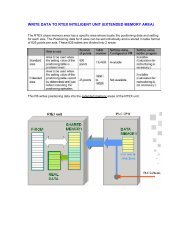
What is multiple transmission?<br />
The <strong>system</strong> transmits signals via two wires to circuits which<br />
are to be switched on and off.<br />
With FULL-2WAY multiple transmission, load addresses<br />
comprised of channel and load numbers are set up in<br />
advance, and the signal is transmitted to the designated<br />
addresses that correspond to <strong>remote</strong> <strong>control</strong>led HID relays<br />
when switches are operated.<br />
With multiple transmission, the signal is transmitted<br />
by pulse signals<br />
What is a pulse signal? Reduced noise level with<br />
the special trapezoidal waveform<br />
for the pulse signal<br />
FULL-2WAY <strong>remote</strong> <strong>control</strong> has the cut-in method of high-speed <strong>control</strong> response and signal indication<br />
In addition to "CYCLIC TIME SHARING MULTIPLE<br />
TRANSMISSION METHOD", a new technology called<br />
the "CUT-IN SIGNAL CIRCUIT" can <strong>control</strong> relays at<br />
high speed and indicate on the ON/OFF status.<br />
5 6<br />
Maximum signal<br />
wiring length<br />
Total signal<br />
wiring length<br />
Extension of<br />
transmission distance<br />
Ambient<br />
temperature range<br />
Power failure backup<br />
500m max. with 1.2 mm dia.wire<br />
(Between transmission unit and the farthest point)<br />
1,500m max. with 1.2 mm - dia wire<br />
with use of 5 amplifiers<br />
(WR 3913-80);<br />
Maximum signal wire distance: 3,000 m,<br />
Total signal wire length: 9,000 m<br />
-10˚C to 50˚C<br />
Flash memory for groups/patterns<br />
(no battery backup)<br />
Switches<br />
1<br />
2<br />
3<br />
4<br />
Control signal<br />
The number is the address<br />
(Load's address)<br />
4<br />
Signal wire:<br />
two signal wires<br />
1 0 0 1 1 0 0 0<br />
1<br />
Transmitted to each load address of the<br />
<strong>control</strong>led signal under the <strong>control</strong>led traffic<br />
The number of signals is limited<br />
only by the number of different<br />
possible arrangements of 0s and<br />
1s, thus making it possible to<br />
handle many signal destinations<br />
(circuits to be switched on and<br />
off).<br />
Pulse signals are transmitted at<br />
an interval of 0.015 second for<br />
each Terminal Unit, so there is no<br />
chance of signal interference in<br />
the two signal wires.<br />
4<br />
1<br />
Pulse signal waveform<br />
FULL-2WAY<br />
<strong>remote</strong> <strong>control</strong><br />
Unique trapezoidal waveform<br />
generates very little noise.<br />
Conventional<br />
multiplex<br />
transmission<br />
Basic transmission format<br />
loads<br />
start mode flag address <strong>control</strong> check sum supervise<br />
signal<br />
waveform<br />
cut-in signal 100 1 1 000<br />
CYCLIC TIME DIVISON<br />
MULTIPLEX TRANSMISSION<br />
dummy<br />
dummy dummy cut-in <strong>control</strong><br />
S1 S0 M3M2M1M0 F1F0 P1P0 A7A6A5••••••A1A0 C7C6C5•••C1C0 U3U2U1U0 R7R6R5•••R3R2R1R0<br />
1<br />
2<br />
3<br />
4<br />
The rectangular waveform<br />
is a source of noise<br />
System Outline
System Outline<br />
Functions and Features of FULL-2WAY Remote Control<br />
Save-Energy, Save-Cost<br />
Timers and sensors can <strong>control</strong> the<br />
<strong>system</strong> to provide light only when<br />
needed. This cuts energy use and<br />
costs. The ability to carry out<br />
centralized monitoring and <strong>control</strong> of<br />
<strong>lighting</strong> for up to 256 circuits makes it<br />
easy to cut unnecessary light use.<br />
Simple Design and<br />
Labor-Saving Installation<br />
The <strong>system</strong> employs a multiplexed<br />
transmission <strong>system</strong> using two nonpolarized<br />
signal wires. This reduces<br />
the number of wires needed<br />
compared to conventional <strong>remote</strong><br />
<strong>control</strong> wiring.<br />
Amenity means user-friendly<br />
Group <strong>control</strong> allows you to <strong>control</strong><br />
multiple <strong>lighting</strong>, turning on or off an<br />
entire section of the building with one<br />
switch. Pattern <strong>control</strong> allows you to<br />
match <strong>lighting</strong> to the time of day or to<br />
the work habits of people in the<br />
building.<br />
Minimal Design, Minimum Maintenance<br />
With the compact wireless address setting<br />
unit, switch functions like pattern and<br />
group <strong>control</strong> along with delayed timing<br />
can be programmed after wiring is<br />
complete. This speeds up the entire<br />
process-from design and estimate to<br />
ordering, delivery, and installation. The<br />
unit also allows you to quickly and easily<br />
change <strong>system</strong> functions.<br />
Flexibility Reduces Total Costs<br />
There's no need to modify the wiring if<br />
<strong>lighting</strong> <strong>control</strong> has to be changed due<br />
to room layout alterations. This<br />
contributes to reduced overall costs.<br />
Centralized monitoring and <strong>control</strong><br />
Control and monitor all <strong>lighting</strong><br />
from a central location.<br />
Switch connection involves merely<br />
connecting two signal wires.<br />
The wires are non-polarized, so there's<br />
less chance of installation errors.<br />
Turn on all lights in<br />
the sales department.<br />
Group <strong>control</strong><br />
Turn off all lights in<br />
the sales department.<br />
Wireless Programming Unit<br />
Mode<br />
Dimmer<br />
Level<br />
Address<br />
setting IND<br />
P/G setting<br />
Initial<br />
Special<br />
P<br />
Individual<br />
Off-delay<br />
Confirm Switch Input Relay<br />
T/U T/U Dimmer<br />
Controlled Address<br />
Load No.<br />
ON/OFF Timer<br />
7<br />
6<br />
G<br />
5<br />
4<br />
5<br />
min<br />
3<br />
2<br />
1<br />
Low Battery<br />
T/U Indication<br />
Wireless<br />
Programming Unit<br />
The wireless address<br />
setting unit has an<br />
LCD that shows the<br />
settings made by the<br />
user, like the example<br />
on the left.<br />
WRT9600-8<br />
Changing of the <strong>lighting</strong> <strong>control</strong><br />
parameters can be carried out easily<br />
using either the group or pattern<br />
switches of the selector switch unit or<br />
the Wireless Programming Unit.<br />
Functional display of <strong>lighting</strong> status<br />
An LED displays <strong>lighting</strong> status.<br />
On: Red LED is lit<br />
All switches are networked via two±24V signal wires.<br />
Distribution<br />
panel board<br />
Relay <strong>control</strong><br />
panel<br />
Two wires<br />
9:00 a.m.<br />
Work starts<br />
Off: Green LED is lit<br />
Turn on<br />
all lights<br />
off Delay<br />
Noon to 1:00 p.m.<br />
Lunch break<br />
Pattern <strong>control</strong><br />
Turn off<br />
some lights<br />
Timer and sensor <strong>control</strong>led<br />
The <strong>system</strong> interconnects devices<br />
like passive infrared ceiling units,<br />
Daylight Sensor Ceiling Unit<br />
Timer setting unit.<br />
(n) locations<br />
Load 1 Load 2 Load 3<br />
Only two wires are required, regardless of the<br />
number of switches.<br />
General-purpose electrical wire can be used.<br />
Two wires<br />
Selector Switch Switch<br />
Note: For types of signal wire, see page 22.<br />
2:00 to 3:00 p.m.<br />
Natural light enters<br />
offices from outside<br />
Turn off<br />
lights near<br />
windows<br />
6:00 p.m.<br />
Turn off<br />
all lights<br />
Four functions in one unit<br />
1. Individual on/off <strong>control</strong><br />
Switch <strong>control</strong>s individual lights. An LED<br />
1-3 shows whether the <strong>lighting</strong> is on or off.<br />
G4 2. Group <strong>control</strong><br />
A single switch <strong>control</strong>s multiple lights, turning<br />
P3<br />
them all on or off with one touch.<br />
WRT5514-8<br />
Switch (4)<br />
(Infrared I/O)<br />
7<br />
Group<br />
5<br />
Group<br />
8<br />
3<br />
Group<br />
Group<br />
6<br />
1<br />
Group<br />
Group<br />
4<br />
3. Pattern <strong>control</strong><br />
A push of the switch changes the <strong>lighting</strong><br />
conditions to a pre-programmed pattern that<br />
matches the time of day or work habits.<br />
4. Timer <strong>control</strong><br />
This can be programmed to automatically<br />
perform tasks like delay the turning on or off of<br />
the lights or to turn the lights on temporarily.<br />
Group<br />
2<br />
Group<br />
Layout change<br />
WRT3655-8<br />
Daylight Sensor Ceiling Unit<br />
7<br />
Group<br />
5<br />
Group<br />
8<br />
3<br />
Group<br />
Group<br />
6<br />
1<br />
Group<br />
Group Group<br />
4<br />
Group<br />
2<br />
Group <strong>control</strong><br />
Turn on and off all lights in an entire section of a building.<br />
Uses<br />
•Offices<br />
•Conference rooms<br />
Effect<br />
•No re-wiring needed<br />
for <strong>lighting</strong> layout<br />
changes<br />
Timer <strong>control</strong><br />
Uses<br />
•Building entrance<br />
•Lobby<br />
•Restrooms<br />
•Elevator area<br />
•Common areas:<br />
restrooms, stairwells<br />
Effect<br />
•Energy saving<br />
•Reduced labor for<br />
<strong>control</strong> and<br />
management<br />
Uses<br />
•Locker rooms<br />
•Coffee rooms<br />
•Restrooms<br />
Effect<br />
•Energy saving<br />
•Reduced labor for<br />
<strong>control</strong> and<br />
management<br />
•Most cost-effective<br />
use of <strong>lighting</strong><br />
Examples of Building Applications Recommendation Number 1<br />
Centralized monitoring and <strong>control</strong><br />
Centralized monitoring and <strong>control</strong> of <strong>lighting</strong> can handle up to<br />
256 circuits per <strong>system</strong>.<br />
Uses<br />
•Building superintendent's office<br />
•Emergency management<br />
center<br />
Effect<br />
•Reduced labor for <strong>control</strong> and<br />
management<br />
•Lights always get turned off<br />
automatically<br />
Pattern <strong>control</strong><br />
The <strong>system</strong> can be programmed to match work schedules or habits, allowing you, for<br />
example, to turn down office <strong>lighting</strong> during lunch hour with a push of a switch.<br />
Uses<br />
•Offices or conference rooms<br />
•Common areas: restrooms,<br />
corridors, hall, stairwells<br />
Effect<br />
•Energy saving-<br />
•Lights only on when necessary<br />
•Lights always get turned off<br />
automatically-<br />
•Turn off all lights together at<br />
end of day<br />
•Optimum <strong>lighting</strong> level-<br />
•For audio-visual presentation<br />
rooms<br />
Lights are turned on or off automatically at a preset time to match a company's daily schedule.<br />
WRT3540K-8<br />
Program Timer Unit<br />
Passive infrared sensor <strong>control</strong><br />
Lights automatically turn on and off as people enter and leave<br />
places like locker rooms.<br />
Lights automatically turn<br />
on upon entering a room.<br />
Passive Infrared Ceiling Unit<br />
Lights can be programmed to turn<br />
off after a certain period<br />
(Approx. 10 sec. to 30 min.)<br />
after people have left a room.<br />
Building entrance<br />
Centralized monitor and <strong>control</strong><br />
from superintendent's office<br />
Wireless <strong>control</strong><br />
Uses<br />
•Conference rooms<br />
•Presentation rooms<br />
•Showrooms<br />
Effect<br />
•Adjust <strong>lighting</strong> as<br />
needed<br />
Corridors<br />
Office area<br />
Option <strong>control</strong><br />
Option <strong>control</strong> Option <strong>control</strong><br />
Lights automatically turn off after a set<br />
time (Approx. 10 sec. to 30 min.)<br />
after the person leaves the room.<br />
Remote <strong>control</strong>ler allows you to manually adjust <strong>lighting</strong>, motorized<br />
equipment during meetings and conferences.<br />
Conferences OHP presentations Audio-visual presentations<br />
Wireless <strong>remote</strong><br />
<strong>control</strong>ler allows<br />
manual <strong>control</strong> in<br />
any situation.<br />
Basic <strong>control</strong><br />
Basic <strong>control</strong> Basic <strong>control</strong><br />
7 8<br />
System Outline
System Outline<br />
Pattern <strong>control</strong>,<br />
operation from various locations Basic <strong>control</strong><br />
Control patterns can be programmed to match specific<br />
times of the day or work routines. Operation can be<br />
carried out using switches located at various doorways<br />
to large factories or warehouses.<br />
Uses Effect<br />
•Factories<br />
•Warehouses<br />
•Cafeterias<br />
•Conference rooms<br />
•Common areas-<br />
Corridors, lobby/hall<br />
Control room<br />
Examples of Building Applications Recommendation Number 2<br />
•Energy saving (Lights only on when necessary)<br />
•Lights always get turned off automatically<br />
(Turn off all lights together at end of day)<br />
•Easy <strong>lighting</strong> <strong>control</strong><br />
Combined <strong>control</strong> of timers and sensors<br />
Option <strong>control</strong><br />
In addition to the timer <strong>control</strong>, Labor-savings<br />
and energy conservation are achieved using<br />
photo sensors that respond to the brightness of<br />
their environment.<br />
Uses Effect<br />
•Lobby •Approach<br />
•Corridor (Staircase) •Outside lights<br />
Localized switches<br />
Localized<br />
switches<br />
•Saving energy<br />
•Labor-saving<br />
WRT3540K-8 WRT3655-8<br />
Program Timer Unit Daylight Sensor Ceiling Unit<br />
Centralized monitoring and <strong>control</strong> Basic <strong>control</strong> Group <strong>control</strong> Basic <strong>control</strong><br />
Centralized monitoring and <strong>control</strong> of the <strong>lighting</strong> Lighting in entire sections of the factory or<br />
in the factory and offices can be carried out from<br />
the superintendent's office.<br />
warehouse can be turned on or off all at once.<br />
Timer <strong>control</strong><br />
Uses<br />
•Control room<br />
•Emergency<br />
center<br />
•Reduced labor for<br />
<strong>control</strong> and<br />
management<br />
•Lights always get turned<br />
off automatically<br />
Option <strong>control</strong><br />
The timer can be set so lights operate based on<br />
people's movements throughout the day, from arriving<br />
at work in the morning to lunch breaks to late night<br />
shift changes.<br />
Uses Effect<br />
•Factories<br />
•Warehouses<br />
•Restrooms<br />
•Elevator areas<br />
•Energy saving<br />
•Reduced labor for <strong>control</strong> and<br />
management<br />
Centralized monitoring and <strong>control</strong><br />
Lightings of arena and seats can be checked at a glance and<br />
centrally <strong>control</strong>led from a <strong>control</strong> room.<br />
Uses Effect<br />
•Control room<br />
•Emergency center<br />
Centralized monitoring and<br />
<strong>control</strong> from a <strong>control</strong> room<br />
Pattern <strong>control</strong><br />
•Saving energy<br />
•Reduced labor for <strong>control</strong><br />
and management<br />
Basic <strong>control</strong><br />
Single push of a switch creates ideal <strong>lighting</strong><br />
environment according to user's needs.<br />
Uses Effect<br />
•Arena<br />
•Seats<br />
Control room<br />
WRT3540K-8<br />
Program Timer Unit<br />
Enables automatic weekly or yearly<br />
<strong>control</strong> of <strong>lighting</strong> by determining the<br />
schedule for one day.<br />
•Energy conservation during<br />
<strong>lighting</strong> operation<br />
Individual switch in a room<br />
Effect Uses<br />
Individual switch in a room<br />
•Individual sections of factories<br />
•Individual sections of warehouses<br />
•Offices<br />
•Conference rooms<br />
Passive infrared sensor <strong>control</strong><br />
Option <strong>control</strong><br />
Lights automatically turn on and off when people enter<br />
and leave. There's no need to worry about people<br />
forgetting to turn off the lights in changing rooms or<br />
coffee rooms.<br />
Uses Effect<br />
•Locker rooms<br />
•Coffee rooms<br />
•Restrooms<br />
Lights automatically turn on<br />
upon entering a room.<br />
Basic <strong>control</strong><br />
Passive infrared ceiling unit<br />
With passive infrared ceiling unit, a person need not be<br />
concerned with the switches ON or OFF of lights in<br />
areas such as restrooms and locker rooms.<br />
Uses Effect<br />
•Locker<br />
•Warehouse<br />
•Restroom<br />
The light of a room turns on<br />
automatically when a person<br />
enters a room.<br />
Effect<br />
•No re-wiring needed for<br />
<strong>lighting</strong> layout changes<br />
•Energy saving<br />
•Reduced labor for <strong>control</strong> and<br />
management<br />
•Energy saving <strong>lighting</strong> <strong>control</strong><br />
Passive Infrared<br />
Ceiling Unit<br />
Lights automatically turn off after a set<br />
time (Approx. 10 sec. to 30 min.)<br />
after the person leaves the room.<br />
•Energy saving<br />
•Reduced labor for <strong>control</strong> and management<br />
•Optimum <strong>lighting</strong> <strong>control</strong><br />
Multiple operation<br />
Lighting <strong>control</strong> from multiple locations is possible<br />
from the cashier's area and from the kitchen.<br />
Uses Effect<br />
•Inside the restaurant<br />
•At the cashier<br />
•Kitchen<br />
Pattern <strong>control</strong><br />
Basic <strong>control</strong><br />
•Reduced labor for <strong>control</strong> and<br />
management<br />
Centralized monitoring and <strong>control</strong><br />
Basic <strong>control</strong><br />
Centralized monitoring and <strong>control</strong> of lights in all<br />
rooms from living room and kitchen allow to check<br />
the lights left on when not in use.<br />
Uses Effect<br />
•In the kitchen<br />
•In the living room<br />
•Energy saving<br />
Option <strong>control</strong><br />
Option <strong>control</strong> Basic <strong>control</strong><br />
Basic <strong>control</strong><br />
Option <strong>control</strong><br />
Passive Infrared<br />
Ceiling Unit<br />
The light is turned off automatically after<br />
a preset interval (ten seconds to thirty<br />
minutes) after the person leaves a room.<br />
Switch installed near the front door to turn off all<br />
lights in a house under pattern <strong>control</strong> is convenient<br />
when leaving in a hurry.<br />
Uses Effect<br />
•Front door •Preventing lights being left on<br />
Presetting an "off-delay" function<br />
allows the lights to be turned off<br />
automatically after you leave.<br />
Combined use of timers and sensors<br />
Energy saving can be achieved by responding<br />
to the arrival pattern of customers and the<br />
amount of natural light.<br />
Uses Effect<br />
•Inside the restaurant<br />
•On the terrace<br />
•Outside <strong>lighting</strong><br />
WRT3540K-8<br />
Program Timer Unit<br />
The unit allows scheduled<br />
<strong>lighting</strong> <strong>control</strong> according<br />
to the business hours from<br />
opening to closing time.<br />
Pattern <strong>control</strong><br />
The <strong>lighting</strong> brightness is selectable under pattern<br />
<strong>control</strong> according to different situations, such as home<br />
entertaining, relaxing with family and other occasions.<br />
Uses Effect<br />
•In the riving room<br />
•In the dining room<br />
•Energy saving<br />
•Reduced labor for <strong>control</strong><br />
and management<br />
Combined use of pattern and dimmer <strong>control</strong><br />
Option <strong>control</strong><br />
Creating a bright atmosphere ideal for each store<br />
with only a single touch of a switch is possible.<br />
Uses Effect<br />
•Inside the •Creating an effective atmosphere<br />
restaurant •Lighting is brightened at lunch time and dimmed<br />
slightly for dinner time, creating a romantic<br />
evening atmosphere<br />
•Reduced labor for <strong>control</strong> and management<br />
Entertaining<br />
at home<br />
Relaxing<br />
with the family<br />
•Creating an atmosphere ideal for<br />
different situations such as a party,<br />
relaxing with family, and mealtimes<br />
Mealtime<br />
All indoor and<br />
outdoor lights on<br />
All indoor lights on<br />
Some lights on Some lights off<br />
9:00 10:00<br />
(17:00) 23:00<br />
All lights off<br />
24:00<br />
Opening Opening<br />
Evening Closing Closing time<br />
preparations<br />
for staff<br />
Timer Timer<br />
EE switch Timer Timer<br />
Passive infrared <strong>control</strong><br />
Option <strong>control</strong><br />
Passive infrared ceiling unit is used to automatically<br />
<strong>control</strong> <strong>lighting</strong> in a restroom, allowing customers to<br />
forget the light switch.<br />
Uses Effect<br />
•Backyard •Energy saving<br />
•Reduced labor for <strong>control</strong> and management<br />
•Optimum <strong>lighting</strong> <strong>control</strong><br />
Passive Infrared Ceiling Unit<br />
Off-delay time may be set within a range<br />
from 10 sec. to 30 min.<br />
Centralized monitoring and <strong>control</strong><br />
Basic <strong>control</strong><br />
Centralized monitoring and <strong>control</strong> allows a person<br />
to <strong>control</strong> the air-conditioning and <strong>lighting</strong> in the<br />
living and dining rooms before<br />
sleeping and when waking-up.<br />
Uses Effect<br />
•In bed rooms •Optimum <strong>lighting</strong><br />
<strong>control</strong><br />
•HA equipment <strong>control</strong><br />
Wireless <strong>control</strong><br />
Wireless <strong>control</strong> allows users to <strong>control</strong> lights of<br />
their own rooms from bed.<br />
Uses Effect<br />
•Rooms for the elderly •Optimum <strong>lighting</strong> <strong>control</strong><br />
9 10<br />
System Outline
System Outline<br />
For spaces such as offices and entire buildings<br />
Running cost<br />
comparison<br />
Normal conditions<br />
98 W X 100 fixtures X 12 hours X 250 days<br />
With program timer unit<br />
(98 W X 100 fixtures X 10 hours + 98 W X 50 fixtures X 2 hours) X 250 days<br />
Program Timer Unit<br />
WRT3540K-8<br />
For spaces such as restrooms and locker rooms<br />
Running cost<br />
comparison<br />
Passive Infrared Unit<br />
WRT3364K-8<br />
Running cost<br />
comparison<br />
Recommending Renovation to Save Energy and Enhance Comfort Operating Switches<br />
Without a passive infrared unit<br />
(31 W X 5 + 22 W X 1 fixture) X 15.5 hours X 250 days<br />
With a passive infrared unit<br />
(31 W X 5 + 22 W X 1 fixture) X 6 hours X 250 days<br />
Normal conditions<br />
98 W X 10 fixtures X 15.5 hours X 250 days<br />
With daylight sensor ceiling unit<br />
98 W X 10 fixtures X 4.8 hours X 250 days<br />
Daylight Sensor Ceiling Unit<br />
WRT3655-8<br />
Realize greater energy savings by using a "Program Timer Unit" to <strong>control</strong><br />
fixed-schedule, reduced <strong>lighting</strong><br />
Fully lit during work Thinned-out <strong>lighting</strong> before start<br />
of work and during lunch break<br />
Lights automatically turn on when<br />
a person enters the room<br />
For spaces such as areas near windows, corridors and elevator halls<br />
Thinned-out <strong>lighting</strong> when natural<br />
light is available from outside<br />
Annual amount of power consumption 29,400 kWh<br />
Annual amount of power consumption 26,950 kWh<br />
Lights automatically turn off after<br />
everyone has left the room<br />
All lights turn on after sunset.<br />
• Times when brightness is forecast to be at<br />
least 200 lx (From Chronological Scientific)<br />
March 21 (Near the vernal equinox): 5:50 to 18:10<br />
June 21 (Near the summer solstice): 4:35 to 19:15<br />
September 21 (Near the autumnal equinox): 5:35 to 17:55<br />
December 21 (Near the winter solstice): 6:50 to 16:55<br />
Times indicated above are for outdoors; indoor times will be shorter.<br />
(Survey data obtained in corridor at our company: 15 minutes difference)<br />
Times will also vary depending on floor level and proximity to windows and walls.<br />
Estimate base on these conditions:<br />
• Usage (work) time: 12 hours (7:30 to 19:30)<br />
• Time schedule <strong>control</strong> provides reduced <strong>lighting</strong><br />
before the start of work and during lunch break.<br />
Before the start of work: 1 hour (7:30 to 8:30)<br />
Lunch break: 1 hour (12:00 to 13:00)<br />
Fully lit: 100 fixtures lit<br />
Reduced <strong>lighting</strong>: 50 fixtures lit<br />
• Lighting fixtures: Hf fluorescent lamps,<br />
32 W X 2 lamps X 100 fixtures<br />
• Annual operation time: 250 days<br />
Realize greater energy savings by combining with a "Passive Infrared Unit" to<br />
<strong>control</strong> on/off automatically<br />
Annual amount of power consumption 685.9 kWh<br />
Annual amount of power consumption 265.5 kWh<br />
Estimate base on these conditions:<br />
• Number of users: Approx. 35 persons<br />
• Use time and time band: 15.5 hours (7:00 to 22:30)<br />
• Passive infrared unit off-delay time: Set to 3 min<br />
( Lit for 6 hours, switches on/off 44 times)<br />
• Lighting fixtures: Twin 27 W X 5 fixtures<br />
20 W fluorescent lamp X 1 lamp X 1 fixture<br />
• Annual operation time: 250 days<br />
Actual measurements by our company<br />
Energy savings<br />
Approximately 8%<br />
Energy savings<br />
Approximately 61%<br />
Realize greater energy savings by combining with<br />
a "Daylight Sensor Ceiling Unit" to <strong>control</strong> on/off automatically<br />
Annual amount of power used 3,797.5 kWh<br />
Annual amount of power used 1,176.0 kWh<br />
Energy savings<br />
Approximately 69%<br />
Estimate base on these conditions:<br />
• Corridor near windows in an office building<br />
• Standard illuminance value of office corridor: 200 lx<br />
• Usage time in office corridor:<br />
15.5 hours (7:00 to 22:30)<br />
• Annual operating time: 250 days<br />
• Times when brightness is forecast to be at least 200 lx indoors<br />
March 21 (Near the vernal equinox): 7:00 to 17:55 ... Approx. 11 hours<br />
June 21 (Near the summer solstice): 7:00 to 19:00 ... Approx. 12 hours<br />
September 21 (Near the autumnal equinox): 7:00 to 17:40 ... Approx. 10.5 hours<br />
December 21 (Near the winter solstice): 7:05 to 16:40 ... Approx. 9.5 hours<br />
(11 H 12 H 10.5 H 9.5 H) 4 15.5 H 0.69 (69% is at least 200 lx)<br />
Time band less than 200 lx where <strong>lighting</strong> switches on: Approx. 4.8 hours (15.5 hours X 31%)<br />
• Lighting fixtures: Hf fluorescent lamps, 32 W X 2 lamps X 10 fixtures<br />
1<br />
3<br />
5<br />
7<br />
9<br />
Switches (Infrared I/O) (COSMO Module)<br />
WRT5501WK-8 WRT5503WK-8 WRT5504WK-8<br />
•Has a simple design and a wide face offering ease of operation for<br />
the elderly.<br />
Switches (Infrared I/O) (FULL-COLOR Module)<br />
WRT5551-8<br />
WRT5552-8 WRT5553-8 WRT5554-8<br />
•FULL-COLOR Module fits on any FULL-COLOR plate.<br />
Master Switch (Surface-mount) (Infrared I/O)<br />
WRT6144WK-8<br />
Central Control and Programming Unit<br />
WRT9103K-89<br />
Card Switch (Dip Switch)<br />
WR3891-8<br />
WRT5731WK-8<br />
Dimmer Switch<br />
WRT5401WK-8<br />
Motor Control Switch<br />
WRT5771-8<br />
Dimmer Switch<br />
•Surface-mounting<br />
installation makes it easy to<br />
work on during renovations.<br />
•Because it's Infrared I/O<br />
address setting type, you<br />
can program individual,<br />
group, and pattern <strong>control</strong>.<br />
WRT6120WK-8 20 circuits<br />
(with Program Setting Unit)<br />
WRT6144WK-8 44 circuits<br />
(with Program Setting Unit)<br />
WRT6168WK-8 68 circuits<br />
(with Program Setting Unit)<br />
WRT6024WK-8 24 circuits<br />
WRT6048WK-8 48 circuits<br />
WRT6072WK-8 72 circuits<br />
•Allows you to carry out<br />
pattern/group <strong>control</strong><br />
settings without the need<br />
for individual switches and<br />
pattern/group setting<br />
switches.<br />
•Allows you to confirm<br />
operation of tasks like<br />
individual, pattern, and<br />
group <strong>control</strong>.<br />
See page 65 for details.<br />
•At the entrance to guest rooms in hotels.<br />
•When used as a card lock <strong>system</strong> for<br />
guest rooms, lights can be set to turn on<br />
or off when cards are inserted or<br />
removed from the lock, thus saving<br />
electricity.<br />
See page 67 for details.<br />
2<br />
4<br />
6<br />
8<br />
WRT9600-8 Wireless Programming Unit<br />
Necessary for address setting of Infrared I/O address setting<br />
type devices<br />
WRT9500K-8 Address setting is available even with<br />
( Wireless Address Setting Unit. )<br />
Switches (Infrared I/O) (Eight Free Module)<br />
WRT5511-8 WRT5512-8 WRT5513-8 WRT5514-8 WRT5518-8<br />
Switches (Infrared I/O) (GLACIER Series)<br />
WRV5601S1-8<br />
Silver Gray<br />
•The GLACIER Series has a sophisticated design that's perfect for<br />
VIP rooms, lobbies, and reception rooms.<br />
•Color blends in with the surroundings. (Silver Gray)<br />
WRV5601S1-8 GLACIER Switch (1)<br />
WRV5602S1-8 GLACIER Switch (2)<br />
WRV5603S1-8 GLACIER Switch (3)<br />
WRV5604S1-8 GLACIER Switch (4)<br />
WRV5831S1-8 GLACIER Dimmer Switch<br />
LCD Appellation Touch Switch<br />
Passive Infrared Ceiling Unit (Infrared I/O)<br />
Lights automatically turn<br />
on upon entering a room.<br />
WRV5602S1-8<br />
Silver Gray<br />
WRT3364K-8<br />
WRV5603S1-8<br />
Silver Gray<br />
Lights automatically turn off after a set time<br />
(between 10 seconds and 30 minutes) after<br />
the person leaves the room.<br />
WRV5604S1-8<br />
Silver Gray<br />
WRV5831S1-8<br />
Silver Gray<br />
Dimmer Switch<br />
Note:<br />
• Name plates are not included.<br />
See page 55 for details.<br />
•Automatically turns on and<br />
off lights in common areas<br />
like restrooms and<br />
corridors.<br />
•Can be programmed for<br />
individual, group, and<br />
pattern <strong>control</strong>.<br />
See page 57 for details.<br />
11 12<br />
WRT 9261-8<br />
System Outline
Control Methods<br />
Method Function<br />
Individual <strong>control</strong><br />
Group <strong>control</strong><br />
Pattern <strong>control</strong><br />
•Turns the load of each circuit on and off individually<br />
Push to<br />
turn on<br />
Push to<br />
turn on<br />
ON<br />
Push again<br />
to turn off<br />
ON ON<br />
Push to<br />
turn on<br />
Push again<br />
to turn off<br />
Circuit<br />
ON<br />
OFF<br />
•Turns multiple circuits on or off within each<br />
preset group.<br />
•Turns dimmer circuits on or off.<br />
OFF OFF OFF<br />
• Turns multiple circuits on/off according to a preset <strong>lighting</strong><br />
pattern<br />
• Changes the dimmer load to a programmed level of brightness<br />
Example of group <strong>control</strong> settings<br />
Lighting fixture layout. The<br />
squares represent the <strong>lighting</strong><br />
fixtures. (One <strong>lighting</strong> fixture per<br />
one circuit.)<br />
Group <strong>control</strong> functions<br />
ON<br />
Push again<br />
to turn off<br />
OFF ON<br />
ON OFF ON<br />
Condition of the load remains the same<br />
Operation Number of circuits to be <strong>control</strong>led Max. no. of circuits Address function Method Function Operations<br />
Push to turn on<br />
( )<br />
Push again to turn off<br />
Push to turn on<br />
( )<br />
Push again to turn off<br />
Pushing again<br />
does not change<br />
( )<br />
anything<br />
1 circuit<br />
Individual circuits<br />
1 - 256<br />
Dimmer circuits<br />
( )<br />
1 - 16<br />
Total of 8 circuits max.<br />
can be programmed in<br />
one group for "on-timer<br />
and off-delay" <strong>control</strong><br />
functions<br />
( )<br />
Individual circuits<br />
1 - 256<br />
Dimmer circuits<br />
( )<br />
1 - 16<br />
Total of 8 circuits max.<br />
can be programmed in<br />
one group for "on-timer<br />
and off-delay" <strong>control</strong><br />
functions<br />
( )<br />
256 circuits<br />
( )<br />
16 dimmer<br />
circuits<br />
(on/off only)<br />
127 groups<br />
72 patterns<br />
Load (individual) addresses<br />
= Load ch. X Load no.<br />
0 ch-1, 0 ch-2, 0 ch-3, 0-ch 4<br />
1 ch-1, 1 ch-2, 1 ch-3, 1-ch 4<br />
63 ch-1, 63 ch-2, 63 ch-3, 63-ch 4<br />
256 circuits = 64 ch X 4<br />
Dimmer addresses 1 - 16<br />
See page 15 for details.<br />
Group addresses<br />
G1 - G127<br />
Pattern addresses<br />
P1 - P72<br />
Group <strong>control</strong> functions Loads up to 256 circuits (+ 16 dimmer circuits) can be turned on or off all at once. Up to 127 groups can be programmed.<br />
Indicator light on<br />
Indicator light off<br />
Pattern <strong>control</strong> functions Loads up to 256 circuits (+ 16 dimmer circuits) can be turned on or off according to preset <strong>lighting</strong> patterns. Up to 72 patterns can be programmed.<br />
Example of pattern <strong>control</strong> settings<br />
Lighting fixture layout. The squares<br />
represent the <strong>lighting</strong> fixtures.<br />
(One <strong>lighting</strong> fixture per one circuit.)<br />
•Explanation of<br />
pattern <strong>control</strong><br />
setting light<br />
symbols<br />
Pattern <strong>control</strong> functions<br />
Indicator light on<br />
Indicator light off<br />
Outline of Control Methods<br />
On setting<br />
Off setting<br />
Not included in<br />
pattern <strong>control</strong><br />
G1<br />
G2<br />
G3<br />
P1<br />
P2<br />
P3<br />
P4<br />
G1<br />
G2<br />
G3<br />
Push switch G1.<br />
Lights included<br />
in the G1 <strong>control</strong><br />
settings turn on.<br />
Push switch P1.<br />
Lights included<br />
in the P1 <strong>control</strong><br />
settings turn on.<br />
Number of circuits to be <strong>control</strong>led by one transmission unit:<br />
Up to 256 circuits plus 16 dimmer circuits can be centrally monitored and <strong>control</strong>led.<br />
Multiple location operation:<br />
Control from multiple locations is possible if you set the same address in the switches.<br />
Basic Control Functions Optional Control Functions<br />
P1<br />
P2<br />
P3<br />
P4<br />
group 1 (G1)<br />
group 2 (G2)<br />
group 3 (G3)<br />
P1<br />
P2<br />
P3<br />
P4<br />
G1<br />
G2<br />
G3<br />
P1<br />
P2<br />
P3<br />
P4<br />
•Push once to<br />
change <strong>lighting</strong><br />
pattern<br />
group 1 (G1) group 2 (G2)<br />
group 3 (G3)<br />
Push switch G1<br />
again.<br />
Lights included<br />
in the G1 <strong>control</strong><br />
settings turn off.<br />
Pattern 1 (P1)<br />
All lights on<br />
Push switch P3.<br />
Lights included in the<br />
P3 <strong>control</strong> settings<br />
turn off and lights not<br />
included in pattern<br />
<strong>control</strong> stay on.<br />
G1<br />
G2<br />
G3<br />
Push switch G2.<br />
Lights included<br />
in the G2 <strong>control</strong><br />
settings turn on.<br />
Pattern 2 (P2)<br />
Only some lights on<br />
P1<br />
P2<br />
P3<br />
P4<br />
Push switch P2.<br />
Certain lights<br />
included in the P2<br />
<strong>control</strong> settings<br />
turn off.<br />
G1<br />
G2<br />
G3<br />
Push switch G3.<br />
Lights included in<br />
the G3 <strong>control</strong><br />
settings turn on.<br />
Lights included in<br />
the G2 <strong>control</strong><br />
settings remain on.<br />
Pattern 3 (P3)<br />
Lights near windows off<br />
P1<br />
P2<br />
P3<br />
P4<br />
Push switch P4.<br />
Lights included in<br />
the P4 <strong>control</strong><br />
settings turn off.<br />
See page 17 for details.<br />
See page 18 for details.<br />
G1<br />
G2<br />
G3<br />
P1<br />
P2<br />
P3<br />
P4<br />
Push switch G3.<br />
Only lights included<br />
in the G3 <strong>control</strong><br />
settings turn off.<br />
Pattern 4 (P4)<br />
All lights off<br />
Push switch P4<br />
again.<br />
Lights remain in<br />
their current state.<br />
(Lights do not<br />
turn on.)<br />
Dimmer <strong>control</strong><br />
(Incandescent lamp)<br />
Group dimmer <strong>control</strong><br />
Fade <strong>control</strong><br />
•Controls the brightness of an incandescent lamp in<br />
a single circuit.<br />
•Turns the lamp on or off with preset light levels.<br />
•Light level indicated on the dimmer switch.<br />
ON<br />
OFF<br />
•Fade <strong>control</strong> is possible when changing<br />
dimmer load to preset brightness with pattern<br />
<strong>control</strong>.<br />
Cautions:<br />
•For a function comparison with the WRT2000 series,WRT2040 series and WRT2050 series Transmission Unit,<br />
see page 41.<br />
•Dimmer, group, and fade <strong>control</strong>s using individual address are not available for the WRT2000-82 Transmission<br />
Unit.<br />
•When using dimmer <strong>control</strong>, dimmer addresses 1-16 are available, however, using individual addresses<br />
is recommended because group and fade <strong>control</strong>s are not available with dimmer addresses 1-16.<br />
Number of circuits<br />
to be <strong>control</strong>led Max. no. of circuits Address function<br />
One dimmer<br />
circuit<br />
Method Function Remarks<br />
On-timer <strong>control</strong><br />
Off-delay <strong>control</strong><br />
Control by external<br />
devices<br />
<strong>Electric</strong>al<br />
equipment <strong>control</strong><br />
Push again<br />
to turn off<br />
the light.<br />
Push to turn<br />
on the light.<br />
With power on<br />
Bright Dark<br />
•Pressing the switch turns on a circuit and turns<br />
it off automatically after a preset time.<br />
(No OFF operation needed)<br />
•Pressing the switch during timer interval turns<br />
off the circuit.<br />
•Pressing the switch turns on a circuit and another<br />
press of the switch turns it off after a preset time.<br />
•Pressing the switch during timer interval does<br />
not turn off the circuit.<br />
•ON/OFF <strong>control</strong><br />
Push to turn on<br />
( )<br />
Push again to turn off<br />
•Controls brightness<br />
with a dimmer switch<br />
Push to make brighter<br />
( )<br />
Push to make darker<br />
•Controls loads automatically with devices like a Timer setting unit<br />
•Controls electrical equipment such as electric rain shutters<br />
•One push to<br />
change the site<br />
Dimmer circuits<br />
using individual<br />
addresses<br />
Circuits<br />
256 using<br />
( circuits ) -(<br />
individual ) <strong>control</strong><br />
•Dimmer <strong>control</strong> is possible by connecting signals (non-volt "a" contact point) from<br />
dimmer level <strong>control</strong> terminal to the Contact input T/U for light <strong>control</strong>.<br />
Brightness is varied while the non-volt "a" contact point is ON.<br />
Circuits<br />
256 using<br />
( circuits ) - ( individual ) <strong>control</strong><br />
•Controls the brightness of each group of<br />
preset multiple dimmer loads.<br />
•Turns on or off with preset brightness.<br />
Push to turn<br />
With power on<br />
on the light.<br />
ON ON ON<br />
OFF OFF OFF<br />
Bright<br />
Push again to<br />
turn off the light.<br />
Dark<br />
•ON/OFF <strong>control</strong><br />
Push to turn on<br />
( Push again to turn off )<br />
•Controls brightness<br />
with a dimmer switch<br />
Push to make brighter<br />
( Push to make darker )<br />
Dimmer circuits<br />
using individual<br />
addresses<br />
Circuits<br />
256 using<br />
( circuits ) -(<br />
individual ) <strong>control</strong><br />
Number<br />
127 of group<br />
( groups ) - ( <strong>control</strong> ) used<br />
Push to turn on<br />
ON state<br />
Push to<br />
turn on<br />
Push to turn on<br />
ON<br />
operation ON<br />
Push to turn on<br />
OFF<br />
operation<br />
After preset<br />
time<br />
Both red and green<br />
ON LEDs on the switch<br />
light.<br />
OFF<br />
ON<br />
Both red and<br />
green LEDs<br />
on the switch<br />
light.<br />
OFF<br />
OFF<br />
72 patterns<br />
Load address<br />
= load ch. X load no.<br />
0 ch-1, 0 ch-2, 0 ch-3, 0-ch 4<br />
1 ch-1, 1 ch-2, 1 ch-3, 1-ch 4<br />
63 ch-1, 63 ch-2, 63 ch-3, 63-ch 4<br />
See page 62 for details.<br />
Group addresses<br />
G1-G127<br />
See page 62 for details.<br />
• Fade time<br />
Fade time may be set to instantaneous,<br />
3 sec., 6 sec. or 1 minute.<br />
• Fade function is applicable to pattern<br />
<strong>control</strong> only.<br />
• Fade time setting is possible only from<br />
a Wireless Programming unit.<br />
Fade <strong>control</strong> is not applicable to turn-off<br />
<strong>control</strong>.<br />
See page 52 for details.<br />
•On-timer may be set at 30 seconds, 1<br />
minute, 5 minutes, 60 minutes or 120<br />
minutes.<br />
•On-timer function is applicable for<br />
individual, dimmer and group <strong>control</strong>s.<br />
•Off-delay timer may be set at 30 seconds,<br />
1 minute or 5 minutes.<br />
•On-timer function is applicable for<br />
individual, dimmer and group <strong>control</strong>s.<br />
•Applicable for individual, dimmer (ON/OFF),<br />
pattern and group <strong>control</strong>s.<br />
On-timer and off-delay See page 53 for details.<br />
<strong>control</strong>s are not available.<br />
•Applicable for dimmer and group dimmer <strong>control</strong>s.<br />
On-timer and off-delay<br />
<strong>control</strong>s are not available. See page 53 for details.<br />
•Individual and pattern <strong>control</strong>s are used<br />
for electrical equipment <strong>control</strong>.<br />
See page 68 for details.<br />
13 14<br />
Control Methods
Basic Functions<br />
Circuit Design for Individual Control<br />
Individual <strong>control</strong>: Controls up to 256 circuits plus 16 dimmer circuits per <strong>system</strong> or per one transmission unit.<br />
Central monitor and <strong>control</strong>, and <strong>control</strong> from multiple locations for up to 256 circuits plus 16 dimmer circuits.<br />
Design Tips for Circuit Divisions<br />
Decide the load to be <strong>control</strong>led by the FULL-2WAY <strong>remote</strong> <strong>control</strong>.<br />
1 Panel configuration<br />
1. Install one transmission unit per <strong>system</strong>.<br />
2. Determine a minimum <strong>control</strong> area and count the number of relays required for circuits. One transmission unit can <strong>control</strong> up to 256<br />
circuits.<br />
3. Check each load capacity per circuit, and for high power, specify 20A HID relays.<br />
For low capacity loads (less than 6A), a T/U is available with a 6A relay unit. For details, see page 21.<br />
4. Install a relay <strong>control</strong> T/U unit for every four (4) 20A HID relays.<br />
Relay <strong>control</strong> T/U units (4-Circuit), and T/U with a 6A-relay units (4-Circuit), up to a maximum of 64 can be connected per one<br />
transmission unit.<br />
5. Install a transformer in each relay <strong>control</strong> panel to simplify wiring.<br />
0-1<br />
0-3<br />
WR6161K-8<br />
WR3400-8 or WRT4014-8<br />
2 Selector switch configuration<br />
Determine the same number of individual switches as the circuits required for centralized monitoring and <strong>control</strong>.<br />
3 Local switches<br />
Determine the individual switches required for local operation.<br />
Address setting: Set the addresses on the Relay Control T/U, then set the same address on the switches.<br />
Address setting method for T/Us(DIP switch): For details, see page 43.<br />
Address setting method for switches and T/Us(Infrared I/O): For details, see page 48.<br />
0ch<br />
Caution: The FULL-2WAY <strong>remote</strong> <strong>lighting</strong> <strong>control</strong> <strong>system</strong> cannot be used<br />
in combination with other <strong>system</strong>s.<br />
Do not use <strong>remote</strong> <strong>control</strong> relays or <strong>remote</strong> <strong>control</strong> transmission <strong>system</strong>s<br />
from other manufacturers.<br />
WR6161K-8<br />
The red LED on an individual switch lights when the relay is ON,<br />
and the Green LED lights when the relay is OFF. The following<br />
exceptions apply:<br />
1. The Green LED lights if the transformer is not powered.<br />
2. Both LEDs remain off if no Relay Control T/U is connected with<br />
a corresponding address.<br />
3. The Green LED (OFF) is lit when no relay is connected to the<br />
Relay Control T/U with the corresponding address.<br />
0-2<br />
0-4<br />
•Transformer<br />
Make sure there is no duplication of Relay Control T/U load addresses. (Not available in US)<br />
Load address<br />
(0ch-1,0ch-2 ... 63ch-3,63ch-4)<br />
Address<br />
• For Load Address: ch.2: 1-4<br />
Load number 1<br />
Load<br />
10 number 3<br />
1<br />
2<br />
4<br />
8<br />
16<br />
32<br />
WR3400-8<br />
Relay Control T/U<br />
Load channel 2<br />
(4-Circuit)<br />
( or WRT4014-8)<br />
Green (with load OFF)<br />
Basic Functions<br />
= load channel [ch] +<br />
(0~63ch)<br />
Channel<br />
Load number 4<br />
LED indication for Individual switches<br />
FULL-COLOR Module<br />
Infrared I/O point<br />
Red (with load ON)<br />
Appellation card<br />
or<br />
Match load<br />
addresses<br />
Load number 2<br />
load number<br />
(1~4)<br />
Number<br />
2-1<br />
2-2<br />
2-3<br />
2-4<br />
WRT5514-8<br />
Switch (4)<br />
(64ch X 4=256)<br />
Each address comprises a Load<br />
channel and a Load number.<br />
Bring the<br />
wireless<br />
address<br />
setting unit<br />
close to the<br />
infrared I/O<br />
point of the<br />
switch (within<br />
1 cm) and set<br />
the addresses<br />
WRT9600-8<br />
Wireless<br />
Programming<br />
Unit<br />
WR2311-851<br />
Mode<br />
Control Address<br />
type number<br />
Address<br />
setting Individual<br />
P/G setting<br />
Initial Individual<br />
Special Individual<br />
ON/OFF<br />
Individual<br />
Timer<br />
Dimmer level<br />
7<br />
6<br />
5<br />
4<br />
3<br />
2<br />
1<br />
Confirm Switch T/U input Relay T/U Dimmer T/U<br />
Battery charge<br />
condition<br />
WRT9500K-8 Wireless Address<br />
( Setting Unit is also available. )<br />
Features of Infrared address setting switch<br />
Any combination of switch addresses<br />
may be set using the wireless address<br />
setting<br />
<br />
Mode<br />
Control Address<br />
type number<br />
Address<br />
setting Individual<br />
P/G setting<br />
Initial Individual<br />
Special Individual<br />
ON/OFF<br />
Individual<br />
Timer<br />
Dimmer level<br />
7<br />
6<br />
5<br />
4<br />
3<br />
2<br />
1<br />
Confirm Switch T/U input Relay T/U Dimmer T/U<br />
Battery charge<br />
condition<br />
Notes on design<br />
• When using dimmer address setting switches, install an amplifier for approximately every 50 circuits. See page 22 for details.<br />
• When using the WRT2050-80 Transmission Unit, use the WR3913K-80 Amplifier, when using WRT2040-894, WRT3912-894<br />
is applicable<br />
Basic wiring diagram for individual <strong>control</strong><br />
•For individual <strong>control</strong> of 16 circuits<br />
Power<br />
source<br />
Lighting<br />
fixtures<br />
0-1<br />
0-3<br />
WR6161K-8<br />
20A HID Relay (Single Pole)<br />
Ry1<br />
Ry3<br />
NS<br />
Signal White<br />
2<br />
1<br />
0ch<br />
4<br />
3<br />
WR6161K-8<br />
20A HID Relay (Single Pole)<br />
Ry2<br />
Ry4<br />
Lighting fixtures<br />
0-2<br />
0-4<br />
1-1<br />
1-3<br />
Ry5<br />
Ry7<br />
1<br />
3<br />
1ch<br />
2<br />
4<br />
Ry6<br />
Ry8<br />
1-2<br />
1-4<br />
FULL-2WAY signal lines<br />
Selector switch<br />
(for Centralized monitoring<br />
and <strong>control</strong>l)<br />
Relay <strong>control</strong> panel L-1<br />
0-1<br />
0-2<br />
0-3<br />
0-4<br />
1-1<br />
1-2<br />
1-3<br />
1-4<br />
Individual <strong>control</strong><br />
WRT5554-8<br />
Switch (4) X 4 units<br />
100-242V AC<br />
Red Blue Red Blue Red Blue Red Blue<br />
WRT2050-80<br />
Transmission Unit<br />
2-1<br />
2-2<br />
2-3<br />
2-4<br />
3-1<br />
3-2<br />
3-3<br />
3-4<br />
Load channel<br />
Signal<br />
Relay <strong>control</strong> panel L-2<br />
1<br />
1P20A 1P20A<br />
2<br />
3 4<br />
20A<br />
HID Relay<br />
NS<br />
Ry1<br />
2ch Ry2<br />
Ry3<br />
Ry4<br />
Ry5<br />
3ch Ry6<br />
Ry7<br />
Ry8<br />
Relay Transformer<br />
WR3913K-80<br />
Amplifier<br />
Control T/U<br />
2-1<br />
2-2<br />
2-3<br />
2-4<br />
WRT5554-8<br />
Switch (4) X 2 units<br />
5<br />
7<br />
9<br />
1-1<br />
1-2<br />
1-3<br />
1-4<br />
RNT<br />
3-1<br />
3-2<br />
3-3<br />
3-4<br />
MCB<br />
1<br />
1P20A 1P20A 2<br />
3 4<br />
WRT5554-8<br />
Switch (4)<br />
6<br />
8<br />
10<br />
WR3400-8<br />
WRT4014-8<br />
Relay Control T/U<br />
(4-Circuit)<br />
or<br />
Relay Control T/U<br />
(4-Circuit) (Infrared I/O)<br />
(Dip switch setting type) (Panel Use)<br />
Load number<br />
Red Blue Red Blue Red Blue Red Blue<br />
WR2311-851<br />
Transformer<br />
24V AC<br />
Blue White<br />
FULL-2WAY signal lines<br />
•Only one (1) transmission unit is installed<br />
even though there are three (3) separate<br />
relay <strong>control</strong> panels.<br />
•It is recommended that each relay <strong>control</strong><br />
panel be equipped with one (1) transformer.<br />
(Not available in U.S)<br />
1-2<br />
3-3<br />
220V AC<br />
Power<br />
source<br />
1-2<br />
4-3<br />
WRT5552-8 WRT5502WK-8<br />
Switch (2)<br />
Switch (2)<br />
(FULL-COLOR Module) (COSMO Module)<br />
Matching of the load addresses of the switches<br />
allows <strong>remote</strong> <strong>control</strong> from multiple locations.<br />
15 16<br />
Local switches<br />
(for Local operation)<br />
Basic Functions
Basic Functions<br />
Circuit Design for Group Control<br />
Group <strong>control</strong>: The basic circuit design is the same as the individual <strong>control</strong>. Up to 127 groups may be configured per <strong>system</strong> or per transmission unit<br />
Simply add group switches and a program setting unit to individual <strong>control</strong> circuits.<br />
• Group <strong>control</strong> setting can be performed by WRT9600-8. (Recommended for up to 50 circuits)<br />
(Group <strong>control</strong> is achieved by setting group/pattern programs after wiring.)<br />
Design Tips for Circuit Divisions<br />
1 Panel configuration<br />
The configuration is the same as individual <strong>control</strong> circuit. (For details, see page 15.)<br />
2 Selector switch configuration: Install Selector switch with Program setting unit in the superintendent's office, etc.<br />
1. Install the same number of individual switches as the circuits.<br />
2. For group <strong>control</strong> setting, add group switches and Program setting unit (WRT5850-8).<br />
For individual <strong>control</strong><br />
Switches<br />
(0ch-1,0ch-2, ... ,63ch-3,63ch-4)<br />
Install according to the number<br />
of load circuits or relays<br />
(1) Set the addresses of the individual and<br />
group <strong>control</strong><br />
switches using the<br />
Wireless<br />
Programming Unit<br />
or the Wireless<br />
Address Setting<br />
Unit.<br />
(For details, see page 45)<br />
+<br />
For group <strong>control</strong><br />
Switches<br />
(G1, ... ,G127)<br />
WRT5850-8<br />
Program Setting Unit<br />
• Do not install the Program Setting Unit<br />
(WRT5850-8) in a common space, to avoid<br />
the set program being modified inadvertently.<br />
WRT9600-8<br />
WRT9600-8<br />
Wireless<br />
Programming Unit<br />
3 Local switches<br />
Install according to the At least one unit required<br />
number of groups needed<br />
FULL-COLOR<br />
Module<br />
COSMO<br />
Module<br />
0_1<br />
0_2<br />
0_3<br />
0_4<br />
1_1<br />
1_2<br />
1_3<br />
1_4<br />
2_1<br />
2_2<br />
2_3<br />
2_4<br />
G1<br />
G2<br />
G3<br />
G4<br />
WRT5850-8<br />
Program Setting<br />
Unit<br />
Install switches for the required number of groups and for the<br />
G1<br />
G1<br />
number of multi-location <strong>control</strong> points.<br />
For individual <strong>control</strong> For group <strong>control</strong><br />
• Make sure that the pattern address on the local switch matches that of<br />
the selector switch to enable <strong>control</strong> from multiple locations.<br />
G2<br />
G2<br />
WRT5554-8<br />
Switch (4)<br />
Infrared I/O<br />
WRT5554-8<br />
Switch (4)<br />
Infrared I/O<br />
Address setting at local switch: Assign the same group address on the local switch to match that of the selector switch.<br />
• Address and pattern settings at selector switch<br />
• Address setting at local switch<br />
LED indications for group switch<br />
Green (with LED on)<br />
FULL-COLOR Module<br />
I/O point<br />
Red (with LED on)<br />
Operation section,<br />
appellation card<br />
(2) Set the group <strong>control</strong> range.<br />
Using Selector Switches, or using Wireless Programming Unit.<br />
(For details, see page 49) (For details, see page 52)<br />
(3) Assign the same group<br />
address on the local<br />
switch to match that of the<br />
group <strong>control</strong> using<br />
Wireless programming<br />
unit or Wireless address<br />
setting unit.<br />
(For details, see page 45)<br />
(1) The Red LED on a group switch lights when all individual switches programmed in the group are turned on.<br />
(2) The Green LED on a group switch lights when all individual switches programmed in the group are turned<br />
off.<br />
(3) Turning one individual switch in the group to ON does not change the Red LED state on the group switch.<br />
(4) The load status shall not be monitored from central location by a group switch.<br />
Basic Wiring Diagram for Group Control •Individual <strong>control</strong>: 16 circuits •Group <strong>control</strong>: 4 groups<br />
Local switches<br />
G1<br />
G2<br />
WRT5502WK-8<br />
Switch (2)<br />
COSMO Module<br />
0-1<br />
0-2<br />
0-3<br />
0-4<br />
WRT5554-8<br />
Switch (4)<br />
Relay <strong>control</strong> panel L-1<br />
1 1P20A<br />
MCB<br />
1P20A 2<br />
3 4<br />
5<br />
6<br />
7<br />
8<br />
9<br />
10<br />
20A HID Relay NS<br />
Ry1<br />
0ch Ry2<br />
Ry3<br />
Ry5<br />
1ch<br />
Ry4<br />
Ry6<br />
Ry7<br />
Ry8<br />
WRT2050-80<br />
Transmission<br />
Unit<br />
Relay<br />
Control T/U<br />
Transformer<br />
0-1<br />
0-2<br />
0-3<br />
0-4<br />
WRT5552-8<br />
Switch (2)<br />
WRT5554-8<br />
Switch (4)<br />
Group addresses of the switches are matched to each other,<br />
allowing <strong>remote</strong> <strong>control</strong> from multiple locations.<br />
G1<br />
G2<br />
RNT<br />
FULL-2WAY signal line<br />
0-1<br />
0-2<br />
0-3<br />
0-4<br />
1-1<br />
1-2<br />
1-3<br />
1-4<br />
2-1<br />
2-2<br />
2-3<br />
2-4<br />
3-1<br />
3-2<br />
3-3<br />
3-4<br />
G1<br />
G2<br />
G3<br />
G4<br />
for individual <strong>control</strong><br />
WRT5554-8<br />
Switch (4) X 4 (Units)<br />
WRT5850-8<br />
Program Setting Unit<br />
Relay <strong>control</strong> panel L-2<br />
RNT<br />
1P20A 1 1P20A<br />
2<br />
3 4<br />
20A HID Relay<br />
NS<br />
Ry1<br />
2ch Ry2<br />
Ry3<br />
Ry5<br />
3ch<br />
Ry4<br />
Ry6<br />
Ry7<br />
Ry8<br />
Relay<br />
Control T/U<br />
Transformer<br />
WR3913K-80<br />
Amplifier<br />
2-1<br />
2-2<br />
2-3<br />
2-4<br />
3-1<br />
3-2<br />
3-3<br />
3-4<br />
WRT5554-8<br />
Switch (4) X 2 (Units)<br />
Only one Transmission Unit is<br />
used although there are separate<br />
relay <strong>control</strong> panels installed.<br />
Transformer must be installed<br />
for wiring configurtation at each<br />
relay <strong>control</strong>.<br />
Selector switch<br />
Local switches<br />
Installed at the <strong>control</strong> room For manual operation<br />
for group <strong>control</strong><br />
WRT5554-8<br />
G3<br />
Switch (4)<br />
WRT5502WK-8<br />
Switch (2)<br />
COSMO Module<br />
marked products are the needed equipment for Individual Control when Group Control<br />
is being performed<br />
G4<br />
Circuit Design for Pattern Control<br />
Pattern <strong>control</strong>: The basic circuit design is the same as the individual <strong>control</strong>.Up to 72 patterns may be configured per <strong>system</strong> or transmission unit<br />
Simply add pattern switches and a program setting unit to the individual <strong>control</strong> circuits.<br />
• Pattern <strong>control</strong> setting can be performed with the (WRT9600-8). (Recommended for up to 50 circuits.)<br />
(Pattern <strong>control</strong> is achieved by setting pattern group programs after wiring.)<br />
Design Tips for Circuit Divisions<br />
1 Panel configuration<br />
The configuration is the same as individual <strong>control</strong> circuit. (For details, see page 15.)<br />
2 Selector switch configuration: Install Selector switch with Program Setting Unit in the superintendent room, etc.<br />
1. Install the same number of individual switches as the circuits.<br />
2. For pattern <strong>control</strong> setting, add pattern switches and Program Setting Unit (WRT5850-8).<br />
For individual <strong>control</strong><br />
Switches<br />
(0ch-1,0ch-2, ... +<br />
,63ch-3,63ch-4)<br />
For pattern <strong>control</strong><br />
Install according to the number<br />
of load circuits or relays<br />
Switches<br />
(P1, ... ,P72)<br />
(1) Set the addresses of the individual and<br />
pattern <strong>control</strong><br />
switches using the<br />
Wireless<br />
Programming Unit<br />
or the wireless<br />
Address Setting<br />
Unit.<br />
(For details, see page 45)<br />
WRT5850-8<br />
Program Setting Unit<br />
• Do not install the Program Setting Unit<br />
(WRT5850-8) in a common space, to avoid<br />
the set program being modified inadvertently.<br />
3 Local switches<br />
Install according to the At least one unit required<br />
number of patterns needed<br />
FULL-COLOR<br />
Module<br />
COSMO<br />
Module<br />
0-1<br />
0-2<br />
0-3<br />
0-4<br />
1-1<br />
1-2<br />
1-3<br />
1-4<br />
2-1<br />
2-2<br />
2-3<br />
2-4<br />
P1<br />
P2<br />
P3<br />
P4<br />
WRT5850-8<br />
Program Setting<br />
Unit<br />
Install switches for the required number of groups and for the<br />
P1<br />
P1<br />
number of multi-location <strong>control</strong> points.<br />
For individual <strong>control</strong> For pattern <strong>control</strong><br />
• Make sure that the pattern address on the local switch matches that of<br />
the selector switch to enable <strong>control</strong> from multiple locations.<br />
P2<br />
P2<br />
WRT5554-8<br />
Switch (4)<br />
WRT5554-8<br />
Switch (4)<br />
Address setting at local switch: Assign the same pattern address on the local switch to match that of the selector switch.<br />
• Address and pattern settings at selector switch • Address setting at local switch<br />
LED indications for group switch<br />
Green (with LED on)<br />
FULL-COLOR Module<br />
I/O point<br />
Red (with LED on)<br />
Operation section,<br />
appellation card<br />
(2) Set the pattern <strong>control</strong> range.<br />
Using selector switches, or Using Wireless programming unit<br />
WRT9600-8<br />
(For details, see page 49) (For details, see page 52)<br />
•Any of the individual, group or pattern switches may be used to <strong>control</strong> a<br />
given load in an overlapping manner. Priority is given to the switch used<br />
most recently for <strong>remote</strong> <strong>lighting</strong> <strong>control</strong>.<br />
•The load remains unchanged even when the same pattern switch is<br />
pushed again.<br />
(3) Assign the same pattern<br />
address on the local<br />
switch to match that of the<br />
pattern <strong>control</strong> using<br />
Wireless Programming<br />
Unit or Wireless Address<br />
Setting Unit.<br />
(For details, see page 45)<br />
(1) The Red LED on a pattern switch lights when the state of every individual switch in the pattern matches<br />
that of the programmed pattern.<br />
If one individual circuit is turned on at a local switch, the LED on the pattern switch changes to green.<br />
Thus load status can be monitored from a central location via the pattern switch.<br />
(2) The Green LED on a pattern switch lights when the state of any of the individual switches in the pattern<br />
does not match that of the programmed pattern.<br />
The Red LED on a pattern switch lights when all of the lights are turned off. ("All-off" pattern)<br />
Basic Wiring Diagram for Pattern Control •Individual <strong>control</strong>: 16 circuits •Pattern <strong>control</strong>: 4 patterns<br />
Local switches<br />
WRT5502WK-8<br />
Switch (2)<br />
0-1<br />
0-2<br />
0-3<br />
0-4<br />
WRT5554-8<br />
Switch (4)<br />
Relay <strong>control</strong> panel L-1<br />
1<br />
MCB<br />
1P20A 2<br />
5<br />
7<br />
9<br />
20A HID Relay<br />
Ry1<br />
Ry3<br />
Ry5<br />
Ry7<br />
WRT2050-80<br />
Transmission<br />
Unit<br />
P1<br />
P2<br />
RNT<br />
3 4<br />
NS<br />
0ch<br />
1ch<br />
Relay<br />
Control T/U<br />
0-1<br />
0-2<br />
0-3<br />
0-4<br />
WRT5552-8<br />
Switch (2)<br />
WRT5554-8<br />
Switch (4)<br />
6<br />
8<br />
10<br />
Ry2<br />
Ry4<br />
Ry6<br />
Ry8<br />
Transformer<br />
Pattern addresses of the switches are matched to each other,<br />
allowing <strong>remote</strong> <strong>control</strong> from multiple locations.<br />
FULL-2WAY signal line<br />
Selector switch<br />
Installed at the <strong>control</strong> room<br />
0-1<br />
0-2<br />
0-3<br />
0-4<br />
1-1<br />
1-2<br />
1-3<br />
1-4<br />
2-1<br />
2-2<br />
2-3<br />
2-4<br />
3-1<br />
3-2<br />
3-3<br />
3-4<br />
P1<br />
P2<br />
P3<br />
P4<br />
for individual <strong>control</strong><br />
WRT5554-8<br />
Switch (4) X 4 (Units)<br />
WRT5850-8<br />
Program Setting Unit<br />
Relay <strong>control</strong> panel L-2<br />
RNT<br />
1P20A 1 1P20A<br />
2<br />
3 4<br />
20A HID Relay NS<br />
Ry1<br />
2ch Ry2<br />
Ry3<br />
Ry4<br />
Ry5<br />
3ch Ry6<br />
Ry7<br />
Ry8<br />
Relay<br />
Control T/U<br />
Transformer<br />
WR3913K-80<br />
Amplifier<br />
for pattern <strong>control</strong><br />
WRT5554-8<br />
Switch (4)<br />
2-1<br />
2-2<br />
2-3<br />
2-4<br />
marked products are the needed equipment for Individual Control when Group Control<br />
is being performed<br />
3-1<br />
3-2<br />
3-3<br />
3-4<br />
WRT5554-8<br />
Switch (4) X 2 (Units)<br />
Only one transmission unit is<br />
used although there are separate<br />
relay <strong>control</strong> panels installed.<br />
Transformer must be installed<br />
for wiring configurtation at each<br />
relay <strong>control</strong>.<br />
17 18<br />
P1<br />
P2<br />
P3<br />
P4<br />
Local switches<br />
For manual operation<br />
WRT5502WK-8<br />
Switch (2)<br />
Basic Functions
Basic Functions<br />
WR6161K-8/WR61613K-8 : Contact Output Specifications<br />
Item Condition Performance<br />
<strong>Electric</strong>al life<br />
Mechanical life<br />
Dielectric strength<br />
Insulation resistance<br />
Temperature rise<br />
<strong>Electric</strong>al life<br />
Mechanical life<br />
Dielectric strength<br />
Insulation resistance<br />
Temperature rise<br />
WR3416K-8/WR3426K-8/WRT4124K-8:<br />
6A Contact Output T/U Specifications<br />
Item Condition Performance<br />
<strong>Electric</strong>al life<br />
Dielectric strength<br />
Insulation resistance<br />
Relay Selecting Chart by Load Capacity<br />
Remote <strong>control</strong> relay selection<br />
How to select the relay to be used<br />
• Choose relays based on the capacity of the load.<br />
HID and other large-capacity loads (20A max.)<br />
Multiple loads per circuit<br />
20A HID Relay<br />
+<br />
Relay Control T/U Transformer<br />
Small-capacity loads (6A max.)<br />
6A Contact Output T/U<br />
Note: Cannot be used with HID loads.<br />
• Because the 6A Contact Output T/U (4-Circuit) does not require a<br />
transformer, relay <strong>control</strong> panels are compact and equipment costs are lower.<br />
Deciding where to install relays<br />
• Relays are usually installed inside the relay <strong>control</strong> panel.However, in the following cases,<br />
relays can be installed in scattered locations, such as on ceilings and inside <strong>lighting</strong> fixtures.<br />
(1) When the EPS is small.<br />
(2) When you want to keep the relay <strong>control</strong> panel compact.<br />
(3) When you want to reduce <strong>lighting</strong> wiring coming from the relay <strong>control</strong> panel.<br />
OUTPUT contact side :<br />
• Resistive load (pf=1)<br />
• Inductive load (pf>0.6)<br />
• Incandescent lamp load<br />
• Fluorescent lamp load<br />
with (conventional) ballast<br />
with high-pf (conventional) ballast<br />
with electronic ballast<br />
self-ballasted compact fluorescent lamp fixture<br />
• High Intensity Discharged (HID) lamp load<br />
AUXILIARY contact side :<br />
• Resistive load (pf=1)<br />
• Resistive load (pf=1)<br />
• Performance frequency : 20 cycles (40 operations)/min<br />
• Between terminals of each OUTPUT (OFF condition)<br />
• Between live parts and non-live metal parts<br />
• Between terminals of OUTPUT and AUXILIARY<br />
• Between terminals of OUTPUT and INPUT<br />
• Between terminals of INPUT and non-live metal parts<br />
• Between terminals of each AUXILIARY<br />
• Main contacts<br />
OUTPUT contact side :<br />
• Resistive load (pf=1)<br />
• Inductive load (pf>0.6)<br />
• Incandescent lamp load<br />
• Fluorescent lamp load<br />
with (conventional) ballast<br />
with high-pf (conventional) ballast<br />
with electronic ballast<br />
self-ballasted compact fluorescent lamp fixture<br />
• High Intensity Discharged (HID) lamp load<br />
AUXILIARY contact side :<br />
• Resistive load (pf=1)<br />
• Resistive load (pf=1)<br />
• Resistive load (pf=1)<br />
• Inductive load (pf>0.6)<br />
• Incandescent lamp load<br />
• Fluorescent lamp load<br />
with (conventional) ballast<br />
with high-pf (conventional) ballast<br />
with electronic ballast<br />
self-ballasted compact fluorescent lamp fixture<br />
• High Intensity Discharged (HID) lamp load<br />
• Between terminals of different pole OUTPUT<br />
• Between live parts and non-live metal parts<br />
• Between terminals of OUTPUT and SIGNAL<br />
• Between terminals of different pole OUTPUT<br />
• Between live parts and non-live metal parts<br />
• Between terminals of OUTPUT and SIGNAL<br />
• Main contacts<br />
20 A 300 V AC<br />
20 A 300 V AC<br />
20 A 250 V AC<br />
20 A 250 V AC<br />
20 A 250 V AC<br />
15 A 250 V AC<br />
15 A 250 V AC<br />
20 A 300 V AC<br />
1 A 125 V AC<br />
0.5 A 250 V AC<br />
• Performance frequency : 20 cycles (40 operations)/min<br />
• Between terminals of different pole OUTPUT<br />
• Between terminals of each OUTPUT (OFF condition)<br />
• Between live parts and non-live metal parts<br />
• Between terminals of OUTPUT and AUXILIARY<br />
• Between terminals of OUTPUT and INPUT<br />
• Between terminals of INPUT and non-live metal parts<br />
• Between terminal of each AUXILIARY<br />
• Between terminals of different pole OUTPUT<br />
• Between terminals of each OUTPUT (OFF condition)<br />
• Between live parts and non-live metal parts<br />
• Between terminals of OUTPUT and AUXILIARY<br />
• Between terminals of OUTPUT and INPUT<br />
• Between terminals of INPUT and non-live metal parts<br />
• Between terminals of each AUXILIARY<br />
• Main contacts<br />
6 A 300 V AC<br />
6 A 300 V AC<br />
6 A 250 V AC<br />
6 A 250 V AC<br />
do not use<br />
1 A 250 V AC<br />
do not use<br />
do not use<br />
30,000 cycles<br />
( 60,000 operations )<br />
60,000 cycles<br />
( 120,000 operations )<br />
2,000 V AC<br />
for 1 min<br />
4,000 V ACfor 1 min<br />
600 V ACfor 1 min<br />
10 M<br />
( 500 V megger )<br />
65 max<br />
high-pf (power factor) : pf > 0.85<br />
WR6166-8/WR61663-8 : Contact Output Specifications<br />
Item Condition Performance<br />
20 A 300 V AC<br />
20 A 300 V AC<br />
20 A 250 V AC<br />
20 A 250 V AC<br />
20 A 250 V AC<br />
15 A 250 V AC<br />
15 A 250 V AC<br />
20 A 300 V AC<br />
1 A 125 V AC<br />
0.5 A 250 V AC<br />
30,000 cycles<br />
( 60,000 operations )<br />
60,000 cycles<br />
( 120,000 operations )<br />
2,000 V AC<br />
for 1 min<br />
600 V ACfor 1 min<br />
10 M<br />
( 500 V megger )<br />
65 max<br />
high-pf (power factor) : pf > 0.85<br />
30,000 cycles<br />
( 60,000 operations )<br />
2,000 V AC<br />
for 1 min<br />
10 M<br />
( 500 V megger )<br />
Temperature rise<br />
65 max<br />
high-pf (power factor) : pf > 0.85<br />
Not applicable to U.S.A market. See page 82 for selecting appropriate items.<br />
WR6161K-84/WR61613K-84 : Contact Output Specifications<br />
Item Condition Performance<br />
<br />
<strong>Electric</strong>al life<br />
<br />
<strong>Electric</strong>al life<br />
Mechanical life<br />
Dielectric strength<br />
Insulation resistance<br />
Temperature rise<br />
<br />
<strong>Electric</strong>al life<br />
<br />
<strong>Electric</strong>al life<br />
Mechanical life<br />
Dielectric strength<br />
Insulation resistance<br />
Temperature rise<br />
<br />
<strong>Electric</strong>al life<br />
<br />
<strong>Electric</strong>al life<br />
Mechanical life<br />
Dielectric strength<br />
Insulation resistance<br />
Temperature rise<br />
WRT4124K-84:<br />
6A Contact Output T/U Specifications<br />
Item Condition Performance<br />
<br />
<br />
<strong>Electric</strong>al life<br />
Dielectric strength<br />
Insulation resistance<br />
Temperature rise<br />
OUTPUT contact side :<br />
• General use<br />
• Tungsten<br />
• (Standard) Ballast<br />
• Moter starting , single phase<br />
• Moter starting , single phase<br />
AUXILIARY contact side :<br />
• General use<br />
• Short circuit rating<br />
OUTPUT contact side :<br />
• General use<br />
• Tungsten<br />
• (Standard) Ballast<br />
• Motor starting , single phase<br />
• Motor starting , single phase<br />
• Performance frequency : 20 cycles (40 operations)/min<br />
• Between terminals of each OUTPUT (OFF condition)<br />
• Between live parts and non-live metal parts<br />
• Between terminals of OUTPUT and AUXILIARY<br />
• Between terminals of OUTPUT and INPUT<br />
• Between terminals of INPUT and non-live metal parts<br />
• Between terminals of each AUXILIARY<br />
• Between terminals of each OUTPUT (OFF condition)<br />
• Between terminals of OUTPUT and INPUT<br />
• Main contacts<br />
OUTPUT contact side :<br />
• General use<br />
• Tungsten<br />
• (Standard) Ballast<br />
• Moter Starting , single phase<br />
• Moter Starting , single phase<br />
AUXILIARY contact side :<br />
• General use<br />
• Short circuit rating<br />
OUTPUT contact side :<br />
• General use<br />
• Tungsten<br />
• (Standard) Ballast<br />
• Moter starting , single phase<br />
• Moter starting , single phase<br />
OUTPUT contact side :<br />
• General use<br />
• Tungsten<br />
• (Standard) Ballast<br />
• Moter starting , single phase<br />
• Moter starting , single phase<br />
AUXILIARY contact side :<br />
• General use<br />
• Short circuit rating<br />
OUTPUT contact side :<br />
• General use<br />
• Tungsten<br />
• (Standard) Ballast<br />
• Moter starting , single phase<br />
• Moter starting , single phase<br />
• General use<br />
• Tungsten<br />
• (Standard) Ballast<br />
• Motor starting , single phase<br />
• Motor starting , single phase<br />
• Between terminals of different pole OUTPUT<br />
• Between live parts and non-live metal parts<br />
• Between terminals of OUTPUT and SIGNAL<br />
• Between live parts and non-live metal parts<br />
• Main contacts<br />
20 A 300 Vac<br />
2400 W 120 Vac<br />
20 A 300 Vac<br />
1/2 HP 110-125 Vac<br />
1-1/2 HP 220-277 Vac<br />
1 A 125 Vac<br />
14,000 A 277 Vac<br />
20 A 347 Vac<br />
2400 W 120 Vac<br />
20 A 300 Vac<br />
1/2 HP 110-125 Vac<br />
1-1/2 HP 220-250 Vac<br />
20 A 300 Vac<br />
2400 W 120 Vac<br />
20 A 300 Vac<br />
1/2 HP 110-125 Vac<br />
1-1/2 HP 220-277 Vac<br />
1 A 125 Vac<br />
5,000 A 277 Vac<br />
20 A 347 Vac<br />
2400 W 120 Vac<br />
20 A 347 Vac<br />
1/2 HP 110-125 Vac<br />
1-1/2 HP 220-250 Vac<br />
• Performance frequency : 20 cycles (40 operations)/min<br />
• Between terminals of different pole OUTPUT<br />
• Between terminals of each OUTPUT (OFF condition)<br />
• Between live parts and non-live metal parts<br />
• Between terminals of OUTPUT and AUXILIARY<br />
• Between terminals of OUTPUT and INPUT<br />
• Between terminals of INPUT and non-live metal parts<br />
• Between terminals of each AUXILIARY<br />
• Between terminals of each OUTPUT (OFF condition)<br />
• Between terminals of OUTPUT and INPUT<br />
• Main contacts<br />
20 A 480 Vac<br />
2400 W 120 Vac<br />
20 A 480 Vac<br />
1/2 HP 110-125 Vac<br />
1-1/2 HP 220-277 Vac<br />
1 A 125 Vac<br />
5,000 A 277 Vac<br />
20 A 347 Vac<br />
2400 W 120 Vac<br />
20 A 347 Vac<br />
1/2 HP 110-125 Vac<br />
1-1/2 HP 220-250 Vac<br />
• Performance frequency : 20 cycles (40 operations)/min<br />
• Between terminals of different pole OUTPUT<br />
• Between terminals of each OUTPUT (OFF condition)<br />
• Between live parts and non-live metal parts<br />
• Between terminals of OUTPUT and AUXILIARY<br />
• Between terminals of OUTPUT and INPUT<br />
• Between terminals of INPUT and non-live metal parts<br />
• Between terminals of each AUXILIARY<br />
• Between terminals of each OUTPUT (OFF condition)<br />
• Between terminals of OUTPUT and INPUT<br />
• Main contacts<br />
6 A 300 Vac<br />
6 A 120 Vac<br />
6 A 300 Vac<br />
1/4 HP 125 Vac<br />
1/4 HP 250 Vac<br />
30,000 cycles<br />
( 60,000 operations )<br />
-<br />
30,000 cycles<br />
( 60,000 operations )<br />
60,000 cycles<br />
( 120,000 operations )<br />
1,694 V AC for 1 min<br />
2,500 V AC for 1 min<br />
600 V AC for 1 min<br />
10 M<br />
( 500 V megger )<br />
65 max<br />
WR6166-84/WR61663-84 : Contact Output Specifications<br />
Item Condition Performance<br />
30,000 cycles<br />
( 60,000 operations )<br />
30,000 cycles<br />
( 60,000 operations )<br />
WR6172-84/WR61723-84 : Contact Output Specifications<br />
Item Condition Performance<br />
-<br />
60,000 cycles<br />
( 120,000 operations )<br />
1,694 V AC for 1 min<br />
2,500 V AC for 1 min<br />
600 V AC for 1 min<br />
10 M<br />
( 500 V megger )<br />
65 max<br />
30,000 cycles<br />
( 60,000 operations )<br />
-<br />
30,000 cycles<br />
( 60,000 operations )<br />
60,000 cycles<br />
( 120,000 operations )<br />
1,960 V AC for 1 min<br />
2,500 V AC for 1 min<br />
600 V AC for 1 min<br />
10 M<br />
( 500 V megger )<br />
65 max<br />
30,000 cycles<br />
( 60,000 operations )<br />
1,600V AC<br />
for 1 min<br />
10 M<br />
( 500 V megger )<br />
65 max<br />
high-pf (power factor) : pf > 0.85<br />
Load capacity<br />
Configuration<br />
Installation<br />
Recommended relays by number of poles<br />
(Double-pole relays) (Single pole relays)<br />
20A max.<br />
6A max. (not for use with HID loads)<br />
Relay Control T/U + 20A HID Relay + Transformer 6A Contact Output T/U (no transformer needed)<br />
Relay <strong>control</strong> panel<br />
JIS approved dimensions (1)<br />
WR6161K-8<br />
• Contact arrangement<br />
Auxiliary<br />
Main circuit<br />
circuit<br />
No auxiliary contact available<br />
for WR6161K-8<br />
• WR6161K-8 / WR6161K-84(UL-Approved) 20A HID Relay (Single Pole)<br />
• WR61613K-8 / WR61613K-84 (UL Approved) 20A HID Relay (Single Pole)<br />
(with Auxiliary Contact)<br />
Wiring Diagram<br />
0-1<br />
Power source<br />
Lighting fixture<br />
Power source<br />
WR2311-851<br />
Transformer<br />
Blue White<br />
Blue<br />
Ry<br />
Red<br />
WR6161K-8<br />
20A HID Relay<br />
20A HID Relay with<br />
JIS approved dimensions (1)<br />
designed for a more compact<br />
relay <strong>control</strong> panel<br />
WR6166-8<br />
To Transmission Unit<br />
(WRT2050-80)<br />
2<br />
1<br />
0ch 4<br />
3<br />
WR3400-8<br />
Relay Control T/U<br />
• Contact arrangement<br />
Main circuit Auxiliary<br />
circuit<br />
• WR6166-8 / WR6166-84(UL Approved) 20A HID Relay (Double Pole)<br />
(JIS approved dimensions (1))<br />
• WR61663-8 / WR61663-84 (UL Approved) 20A HID Relay (Double Pole)<br />
(JIS approved dimensions (1))<br />
(with Auxiliary Contact)<br />
• WR6172-84 (UL Approved) / WR61723-84 (UL Approved)<br />
Wiring Diagram<br />
0-1<br />
Lighting fixture<br />
Power source<br />
Power source<br />
WR2311-851<br />
Transformer<br />
Blue White<br />
Blue<br />
Ry<br />
Red<br />
WR6166-8<br />
20A HID Relay<br />
(NO)<br />
No auxiliary contact available<br />
for WR6166-8<br />
To Transmission Unit<br />
(WRT2050-80)<br />
2<br />
1<br />
0ch 4<br />
3<br />
WR3400-8<br />
Relay Control T/U<br />
(CON)<br />
(NC)<br />
Caution:<br />
The FULL-2WAY <strong>remote</strong> <strong>lighting</strong> <strong>control</strong> <strong>system</strong> cannot be<br />
used in combination with other <strong>system</strong>s.<br />
Do not use <strong>remote</strong> <strong>control</strong> relays or <strong>remote</strong> <strong>control</strong><br />
transmission <strong>system</strong>s from other manufactures.<br />
Wiring Diagram<br />
WR3416K-8<br />
• WR3416K-8 6A Contact Output T/U<br />
(4-Circuit)<br />
• WR3426K-8 6A Contact Output T/U<br />
(1-Circuit)<br />
Power source<br />
0-1<br />
0-2<br />
0-3<br />
0-4<br />
Lighting<br />
fixture<br />
10A Contact Output T/U<br />
Wiring Diagram<br />
Specifications<br />
To Transmission<br />
Unit<br />
(WRT2050-80)<br />
0ch<br />
WR3416K-8<br />
6A Contact Output T/U<br />
(4-Circuit)<br />
WR3443-8<br />
• WR3443-8 (4-Circuit)<br />
Power source<br />
0-1<br />
0-2<br />
0-3<br />
0-4<br />
Lighting<br />
fixture<br />
To Transmission<br />
Unit<br />
(WRT2050-80)<br />
0ch<br />
WR3443-8<br />
10A Contact Output T/U<br />
(4-Circuit)<br />
Signal Voltage<br />
From ±18 V to ±30 V<br />
Signal Current Consumption Less than 3 mA<br />
<strong>Electric</strong> Life<br />
Resistive Load (Pf = 1)<br />
10 A AC 250 V 100,000 cycles<br />
Inductive Load (Pf: more than 0.6) 10 A AC 250 V 100,000 cycles<br />
Incandescent lamp Load<br />
10 A AC 250 V 100,000 cycles<br />
Fluorescent lamp Load<br />
(containing electronic ballast)<br />
10 A AC 250 V 100,000 cycles<br />
High intensity Discharged lamp Load 10 A AC 250 V 100,000 cycles<br />
Temperature Rise Main contact Less than 55<br />
Insulation Resistance Between live parts and non-live parts<br />
Between live parts of different polarity<br />
Between live parts and signal terminals<br />
More than 100MΩ<br />
<strong>Electric</strong> Strength Between live parts and non-live parts<br />
Between live parts of different polarity<br />
Between live parts and signal terminals<br />
2000 V/min.<br />
Terminal Intensity More than 1.2 N m<br />
19 20<br />
Basic Functions
Basic Functions<br />
Circuit Design for 6A 10A Contact Output T/U (Dip Switch)<br />
WR3416K-8<br />
6A Contact Output T/U<br />
(Single Pole) (4-Circuit)<br />
WR3443-8<br />
10A Contact Output T/U<br />
(4-Circuit)<br />
Features<br />
6A.10A Contact Output Terminal Units do<br />
not require a transformer, thus allowing<br />
more compact relay <strong>control</strong> panels.<br />
Mounting space can be reduced to half.<br />
• The use of 6A Contact Output T/Us does not require a transformer. T/U relay itself is one unit, thus reduction of space<br />
and cost can be achieved.<br />
Set addresses using the dip switches on the T/U. (Set address<br />
may be visually confirmed.) (For address settings, see page 43.)<br />
• Features<br />
Different load channel can be set to a Single Relay Control T/U (or a Single 6A<br />
Contact Output T/U)<br />
For the address setting method, see page 48.<br />
For Small-capacity Load (6A max.) per Circuit<br />
Note: Do NOT use with HID loads.<br />
(6A Contact Output T/U)<br />
Use 20A HID Relay. or 10A Contact<br />
Output T/U.<br />
• 20A HID Relay • 6A Contact Output T/U<br />
0-1<br />
0-3<br />
Lighting<br />
fixture<br />
Ry1<br />
Ry3<br />
Red Blue<br />
Red Blue<br />
WR6161K-8<br />
20A HID Relay<br />
• 6A Contact Output T/U (Single Pole) (WR3416K-8)<br />
• 10A Contact Output T/U (Single Pole) (WR3443-8)<br />
Signal<br />
4 7 8<br />
3 5 6<br />
2 3 4<br />
1 1 2<br />
Load channel<br />
2+8=ch.10<br />
Load numbers<br />
1-4-fixed<br />
10<br />
1<br />
2<br />
4<br />
8<br />
16<br />
32<br />
2<br />
1<br />
0ch<br />
4<br />
3<br />
WR3400-8<br />
Relay Control T/U<br />
Address Setting for 6A 10A Contact Output T/U (4-Circuit)<br />
WR2311-851<br />
Transformer<br />
Red Blue Red Blue<br />
Ry2<br />
Ry4<br />
WR6161K-8<br />
20A HID Relay<br />
0-2<br />
0-4<br />
Wiring Diagram<br />
Power<br />
source<br />
0ch<br />
WR3416K-8<br />
6A Contact Output T/U<br />
(Single Pole)(4-Circuit)<br />
Power source<br />
0-1<br />
0-2<br />
0-3<br />
0-4<br />
Lighting<br />
fixture<br />
Circuit Design for Relay Control T/U (Infrared I/O) and 6A Contact Output T/U (Infrared I/O)<br />
WRT9600-8 LCD Panel<br />
Mode<br />
Controlled Address<br />
Load number<br />
Timer<br />
Address<br />
setting Individual<br />
P • G SET<br />
Initial Individual<br />
Special Individual<br />
Switch<br />
ON/OFF<br />
Dimmer level<br />
7<br />
6<br />
Individual<br />
5<br />
4<br />
3<br />
2<br />
1<br />
T/U input Relay T/U Dimmer T/U<br />
Low Battery<br />
Indication<br />
0-4<br />
0-3<br />
0-2<br />
0-1<br />
WRT2050-80<br />
Transmisson Unit<br />
0ch<br />
WR3416K-8<br />
6A Contact Output T/U<br />
(Single Pole)(4-Circuit)<br />
To switch/relay <strong>control</strong> panel<br />
WRT4124K-8<br />
WRT4124K-84<br />
6A Contact Output T/U<br />
(Single Pole)<br />
(4-Circuit)(Infrared I/O)<br />
FULL-2WAY signal line<br />
WRT4014-8<br />
Relay Control T/U<br />
(4-Circuit) (Infrared I/O)<br />
Amplifier<br />
(1) Calculation method for FULL-2WAY signal current<br />
It is recommended, when using infrared I/O Switches, to<br />
install one Amplifier per approx 50 relay circuits.<br />
Ex. 50 circuits (signal current consumption)<br />
Relay <strong>control</strong> T/U<br />
Selector switch section<br />
WR3400-8 1.2mA X 13<br />
Individual switches WRT5554-8 12mA X 13<br />
Pattern switch WRT5554-8 12mA X 1<br />
Program setting unit WRT5850-8 5mA X 1<br />
Local switches WRT5551-8 6mA X 50<br />
Total signal current consumption...489mA<br />
• Output signal current from a Transmission Unit is 500mA. Be sure to use an<br />
Amplifier when the total signal current of components, such as Switches<br />
and Relay Control T/Us, exceeds 500mA.<br />
(For signal current of Switches and Terminal Units, see their respective<br />
ratings in the "Products" section.)<br />
• A 500mA signal current is supplied per Amplifier.<br />
• A signal current of 3000mA can be supplied when the maximum of five<br />
Amplifiers are installed in a <strong>system</strong>.<br />
Example Under Wiring Method (1)<br />
• Transmission Unit to Amplifier A1 +Transmission Unit to Amplifier B1
Products<br />
Distribution Panel Board<br />
and Relay Control Panel<br />
Inside Relay Control Panel<br />
Transmisstion Unit Relay Control T/U<br />
WRT2050-80(WRT2040-894) WR3400-8<br />
Transformer 20A HID Relay<br />
Amplifier<br />
FULL-2WAY System Components<br />
WR3913K-80(WR3912-894)<br />
Central Control and<br />
Programming Unit Selector Switch<br />
T U<br />
C P U Ry–T/U<br />
WR2311-851 WR6161K-8(WR6161K-84)<br />
R–Tr R–Ry<br />
AMP<br />
4<br />
Legend:<br />
R52<br />
R50<br />
R49<br />
T/U<br />
A-2<br />
RS<br />
L-2 R50<br />
RG2<br />
R1<br />
R2<br />
R3<br />
R4<br />
R50<br />
R<br />
R5<br />
R6<br />
RG2<br />
R7<br />
R8<br />
R49<br />
FULL-2WAY<br />
Signal line (2 wires)<br />
Wireless<br />
Signal line (2 wires)<br />
Power line<br />
WRT9103K-89<br />
RS<br />
R51 R52 R51 R52 R51 R52<br />
MR<br />
R50<br />
R<br />
Control<br />
room<br />
Toilet<br />
R49 R51<br />
R9 R13<br />
R10<br />
R11<br />
R12<br />
R14<br />
R15<br />
R16<br />
RG<br />
R17<br />
R18<br />
RG4<br />
R<br />
R19<br />
R20<br />
R51 R51<br />
Toilet<br />
MR<br />
MR<br />
R<br />
R21<br />
R22<br />
R23<br />
R24<br />
MR<br />
R52<br />
R53<br />
R54<br />
R55<br />
R56<br />
MR<br />
MR<br />
MR<br />
MR<br />
R25 R29<br />
R26<br />
R27<br />
R28<br />
R30<br />
R31<br />
R32<br />
Meeting<br />
room<br />
R49<br />
MR<br />
MR<br />
R50<br />
MR<br />
R49<br />
MR2<br />
R33<br />
R34<br />
MR OR<br />
R50 R49 R50 R49 R50 R49 R50<br />
Contact Input T/U<br />
Timer Setting Unit<br />
WRT3224-8<br />
Input T/U 4<br />
WRT3540K-8<br />
TM<br />
R<br />
MR2<br />
RG4<br />
R37<br />
R38<br />
R41<br />
R42<br />
RG4<br />
RG4<br />
R R<br />
R35<br />
R39<br />
R43<br />
R47 R39<br />
R36<br />
Dimmer Control T/U<br />
(500W)(230V)<br />
R57<br />
R58<br />
R59<br />
R61<br />
R60 R62<br />
WRT4345-82<br />
10A Contact Output T/U<br />
WR3443-8<br />
R<br />
R40<br />
LC<br />
500<br />
Small<br />
conference<br />
room<br />
R51 R52<br />
MR4<br />
Large<br />
conference<br />
room B<br />
R44<br />
R6<br />
R64<br />
R<br />
MR4<br />
R51<br />
MR4<br />
R52<br />
R56<br />
RG1 Large<br />
conference<br />
room A<br />
R<br />
MR4 MR4 MR4<br />
R45<br />
R46<br />
R48<br />
R49 R50<br />
RG4<br />
MR4<br />
MR4<br />
R52 R51<br />
R37 R33 R29 R25 R21<br />
R38<br />
R40<br />
Passive Infrared<br />
Ceiling Unit<br />
R34<br />
R35<br />
R36<br />
R55<br />
R51<br />
RG1<br />
RD<br />
R30<br />
R31<br />
R32<br />
R54<br />
R53<br />
WRT3364K-8<br />
R26<br />
R27<br />
R28<br />
S R<br />
R22<br />
RG4<br />
R<br />
R23<br />
R24<br />
R52<br />
R51<br />
R52<br />
R17<br />
R18<br />
R19<br />
R20<br />
Daylight Sensor<br />
Ceiling Unit<br />
R52 R51<br />
R13<br />
R47<br />
R48<br />
MR2<br />
R14<br />
R15<br />
R16<br />
MR2<br />
RG2<br />
R<br />
MR2<br />
R49 R50 R49 R50 R49<br />
MR4<br />
R43<br />
R9<br />
R10<br />
R11<br />
R12<br />
R46<br />
Lobby<br />
GG4 RG2 RG2<br />
Switches (Eight Free Module)<br />
R44<br />
R5 R1<br />
R6<br />
R7<br />
R8<br />
R2<br />
RG2<br />
R<br />
R3<br />
R4<br />
WRT3655-8<br />
R41<br />
R45<br />
T/U<br />
A-1<br />
WRT5511-8 WRT5512-8 WRT5513-8 WRT5514-8 WRT5718-8 WRT5501WK-8 WRT5502WK-8 WRT5503WK-8<br />
R42<br />
L-1<br />
Card Operation Switch<br />
WR3891-8<br />
Wireless Address Setting Unit<br />
Switches<br />
(COSMO Module)<br />
R1 R2 R3 R4 R8<br />
R1 R2 R3<br />
SS R<br />
WRT5504WK-8 WRT5731WK-8<br />
WRT9500K-8<br />
Wireless Programming Unit<br />
R4 MR<br />
WRT9600-8<br />
Master<br />
Switch(20)<br />
RC<br />
WRT6120WK-8<br />
Also<br />
R20<br />
Available<br />
44 Circuit<br />
(WRT6144WK-8)<br />
68 Circuit<br />
(WRT6168WK-8)<br />
23 24<br />
Products
Products<br />
Switches<br />
Switches (COSMO Module) ... For applicable plates, see page 35.<br />
(1)<br />
(2)<br />
Notice: Our <strong>remote</strong> <strong>control</strong> <strong>system</strong> products are not compatible with those of other manufacturers and should not be<br />
used in combination with any such products. Always use Matsushita <strong>Electric</strong> Co. Ltd. <strong>remote</strong> <strong>control</strong> relays,<br />
breakers and transformers.<br />
Always use WRT**** series Transmission Unit when using infrared I/O address type components.<br />
Symbol in<br />
Model No. Description Rating Remarks<br />
diagram<br />
WRT5501WK-8<br />
WRT5501WK-8 WRT5502WK-8<br />
WRT5502WK-8<br />
(3)<br />
(4)<br />
WRT5503WK-8 WRT5504WK-8<br />
(1)<br />
WRT5551-8<br />
WRT5731WK-8<br />
WRT5552-8<br />
(3)<br />
WRT5553-8<br />
(2)<br />
(4)<br />
WRT5554-8<br />
WRT5771-8<br />
WRT5503WK-8<br />
WRT5504WK-8<br />
WRT5731WK-8<br />
WRT5771-8<br />
Switch (1) (Infrared I/O)<br />
(COSMO Module) (White)<br />
Switch (2) (Infrared I/O)<br />
(COSMO Module) (White)<br />
Switch (3) (Infrared I/O)<br />
(COSMO Module) (White)<br />
Switch (4) (Infrared I/O)<br />
(COSMO Module) (White)<br />
Dimmer Switch<br />
(Infrared I/O Type)<br />
(COSMO Module) (White)<br />
Dimmer Switch<br />
(Infrared I/O Type)<br />
(FULL-COLOR Module)<br />
Signal current<br />
6 mA<br />
Signal current<br />
8 mA<br />
Signal current<br />
10 mA<br />
Signal current<br />
12 mA<br />
Signal current<br />
10 mA<br />
Switches (Eight Free Module) ... For details of plates to use, see page 55.<br />
(1)<br />
WRT5511-8<br />
(3)<br />
WRT5513-8<br />
(8)<br />
WRT5518-8<br />
Products<br />
(2)<br />
WRT5512-8<br />
(4)<br />
WRT5514-8<br />
WRT5511-8<br />
WRT5512-8<br />
WRT5513-8<br />
WRT5514-8<br />
WRT5518-8<br />
Switch (1)<br />
(Infrared I/O)<br />
(Eight Free Module)<br />
Switch (2)<br />
(Infrared I/O)<br />
(Eight Free Module)<br />
Switch (3)<br />
(Infrared I/O)<br />
(Eight Free Module)<br />
Switch (4)<br />
(Infrared I/O)<br />
(Eight Free Module)<br />
Switch (8)<br />
(Infrared I/O)<br />
(Eight Free Module)<br />
Switches (FULL-COLOR Module) ... For applicable plates, see page 36.<br />
Signal current:<br />
6 mA<br />
Signal current:<br />
7 mA<br />
Signal current:<br />
8 mA<br />
Signal current:<br />
9 mA<br />
Signal current:<br />
14 mA<br />
Signal current<br />
10 mA<br />
• R<br />
• R2<br />
• R3<br />
• R4<br />
WRT5551-8 •R Switch (1)<br />
Signal current<br />
(Infrared I/O)<br />
6 mA<br />
(FULL-COLOR Module)<br />
WRT5552-8 •R2 Switch (2)<br />
Signal current<br />
(Infrared I/O)<br />
8 mA<br />
(FULL-COLOR Module)<br />
WRT5553-8 •R3 Switch (3)<br />
Signal current<br />
(Infrared I/O)<br />
10 mA<br />
(FULL-COLOR Module)<br />
WRT5554-8 •R4 Switch (4)<br />
Signal current<br />
(Infrared I/O)<br />
12 mA<br />
(FULL-COLOR Module)<br />
MR<br />
• R<br />
• R2<br />
• R3<br />
• R4<br />
R8<br />
MR<br />
Applicable to<br />
COSMO Module<br />
1-Gang<br />
switch plates<br />
(Non volatile<br />
memory used)<br />
Applicable to<br />
COSMO Module<br />
switch plates<br />
(1-Gang)<br />
(Non-volatile<br />
memory used)<br />
Applicable to<br />
Plates (1-Gang)<br />
Applicable to<br />
FULL-COLOR<br />
plates(1)<br />
(Non-volatile<br />
memory used)<br />
Applicable to<br />
FULL-COLOR<br />
plates (3)<br />
(Non-volatile<br />
memory used)<br />
• Signal current: Rated input signal current (Name displayed on units) • Signal current: Rated input signal current (Name displayed on units)<br />
•Dimensions (units: mm)<br />
WRT5501WK-8<br />
I/O point<br />
42.4<br />
45<br />
25.2 24.9<br />
83.5<br />
WRT5502WK-8<br />
42.4<br />
45<br />
25.2 24.9<br />
101<br />
110<br />
91.4<br />
WRT5503WK-8 WRT5504WK-8<br />
42.4<br />
45<br />
25.2 24.9<br />
101<br />
110<br />
91.4<br />
83.5<br />
101<br />
110<br />
91.4<br />
WRT5731WK-8<br />
42.4<br />
45<br />
25.2 24.9<br />
101<br />
110<br />
91.4<br />
WRT5771-8<br />
I/O point<br />
28<br />
22.5 23.5<br />
0.7<br />
9.5 20.7<br />
69<br />
0.7<br />
9.5 20.7<br />
69<br />
0.7<br />
9.5 20.7<br />
83.5<br />
101<br />
110<br />
68.7<br />
69<br />
3.7 8<br />
7.8 27.4<br />
42.4<br />
45<br />
25.2 24.9<br />
WRT5511-8 WRT5512-8<br />
42.4<br />
45<br />
25.2 24.9<br />
42.4<br />
45<br />
25.2 24.9<br />
WRT5551-8 WRT5552-8<br />
I/O<br />
point<br />
44<br />
28<br />
22.7<br />
8<br />
27.2<br />
WRT5553-8<br />
28<br />
22.5 23.5<br />
101<br />
110<br />
WRT5513-8<br />
42.4<br />
45<br />
25.2 24.9<br />
101<br />
110<br />
WRT5518-8<br />
101<br />
110<br />
83.5<br />
110<br />
68.7<br />
3.7<br />
7.8<br />
8<br />
27.4<br />
72<br />
28<br />
22.5 23.5<br />
72<br />
83.5<br />
83.5<br />
83.5<br />
110<br />
68.7<br />
101<br />
110<br />
91.4<br />
3.7<br />
7.8<br />
WRT5554-8<br />
I/O<br />
point<br />
28<br />
22.5 23.5<br />
83.5<br />
110<br />
68.7<br />
3.7<br />
7.8<br />
0.7<br />
9.5 20.7<br />
0.7<br />
9.5 20.7<br />
8<br />
27.4<br />
72<br />
8<br />
27.4<br />
69<br />
69<br />
COSMO Module<br />
appellation card size<br />
(solid color)<br />
9.5<br />
42.4<br />
45<br />
25.2 24.9<br />
WRT5514-8<br />
9<br />
101<br />
110<br />
42.4<br />
45<br />
25.2 24.9<br />
101<br />
110<br />
23.5<br />
72<br />
FULL-COLOR<br />
appellation<br />
card size<br />
(solid color)<br />
9.4<br />
91.4<br />
9.3 20.7<br />
19.4<br />
69<br />
Eight Free<br />
appellation card size<br />
38<br />
Switches, Setting Devices<br />
Switches (GLACIER Series) ... For details of plates to use, see page 35.<br />
(1)<br />
WRV5601S1-8<br />
(4)<br />
WRV5604S1-8<br />
Master Switches (Surface Mount)<br />
(20 circuits)<br />
WRT6120WK-8<br />
(44 circuits)<br />
WRT6144WK-8<br />
(24 circuits)<br />
WRT6024WK-8<br />
(2)<br />
WRV5602S1-8<br />
WRT5850-8<br />
Symbol in<br />
Model No. Description Rating Remarks<br />
diagram<br />
WRV5601S1-8<br />
WRV5602S1-8<br />
WRV5603S1-8<br />
WRV5604S1-8<br />
WRV5831S1-8<br />
WRT6120WK-8<br />
WRT6144WK-8<br />
WRT6168WK-8<br />
WRT6024WK-8<br />
WRT6048WK-8<br />
WRT6072WK-8<br />
Switch (1)<br />
(Infrared I/O)<br />
(GLACIER Series)<br />
(Silver Gray)<br />
Switch (2)<br />
(Infrared I/O)<br />
(GLACIER Series)<br />
(Silver Gray)<br />
Switch (3)<br />
(Infrared I/O)<br />
(GLACIER Series)<br />
(Silver Gray)<br />
Switch (4)<br />
(Infrared I/O)<br />
(GLACIER Series)<br />
(Silver Gray)<br />
Dimmer Switch<br />
(Infrared I/O)<br />
(GLACIER Series)<br />
(Silver Gray)<br />
Master Switch (20)<br />
(Infrared I/O)<br />
(with Program Setting Unit)<br />
Master Switch (44)<br />
(Infrared I/O)<br />
(with Program Setting Unit)<br />
Master Switch (68)<br />
(Infrared I/O)<br />
(with Program Setting Unit)<br />
Master Switch (24)<br />
(Infrared I/O)<br />
Master Switch (48)<br />
(Infrared I/O)<br />
Master Switch (72)<br />
(Infrared I/O)<br />
Signal current:<br />
6 mA<br />
Signal current<br />
65 mA<br />
Signal current<br />
137 mA<br />
Signal current<br />
209 mA<br />
Signal current<br />
72 mA<br />
Signal current<br />
144 mA<br />
Signal current<br />
216 mA<br />
Program Setting Unit... For setting details, please see pages 49 & 50<br />
WRT5850-8 •RS Program Setting Unit Signal current<br />
(FULL-COLOR Module) 5 mA<br />
Surface-mount<br />
type<br />
(Non-volatile<br />
memory used)<br />
Use Transmission<br />
Unit WRT2050-80<br />
series<br />
Applicable to<br />
FULL-COLOR<br />
plates (3)<br />
This device should not be installed in a location where people can easily manipulate<br />
• R<br />
Signal current:<br />
8 mA • R2 Applicable to<br />
GLACIER Series<br />
Plates (1-Gang)<br />
Signal current:<br />
10 mA<br />
Signal current:<br />
12 mA<br />
Signal current:<br />
10 mA<br />
LCD Appellation Touch Switch... For details of plates to use, see page 55.<br />
WRT9261-8<br />
WRT9261-8<br />
LCD Appellation<br />
Touch Switch<br />
Rated Current<br />
Consumption<br />
200 mA<br />
Rated Signal<br />
Current<br />
Consumption<br />
15 mA<br />
• R3<br />
• R4<br />
MR<br />
R20<br />
RS<br />
R44<br />
RS<br />
R68<br />
RS<br />
R24<br />
R48<br />
R72<br />
(Non-volatile<br />
memory used)<br />
Appellation<br />
card cannot<br />
be mounted.<br />
•Dimensions (units: mm)<br />
I/O point<br />
42.4<br />
45<br />
25.2 24.9<br />
WRT5850-8<br />
28<br />
22.5 23.5<br />
WRV5601S1-8 WRV5602S1-8<br />
42.4<br />
45<br />
25.2 24.9<br />
101<br />
110<br />
WRT6120WK-8 WRT6144WK-8<br />
120<br />
83.5<br />
101<br />
110<br />
64<br />
418<br />
1<br />
25<br />
68.7<br />
3.7<br />
7.8<br />
11.8<br />
WRT6168WK-8<br />
95<br />
310<br />
WRT6024WK-8 WRT6048WK-8<br />
120<br />
64<br />
418<br />
1<br />
25<br />
101<br />
110<br />
42.4<br />
45<br />
25.2 24.9<br />
WRT6072WK-8<br />
95<br />
310<br />
8<br />
27.4<br />
95<br />
95<br />
72<br />
101<br />
110<br />
64<br />
418<br />
1<br />
25<br />
64<br />
418<br />
1<br />
25<br />
42.4<br />
45<br />
25.2 24.9<br />
95<br />
215<br />
95<br />
215<br />
101<br />
110<br />
WRV5603S1-8 WRV5604S1-8 WRV5831S1-8<br />
25 26<br />
R24<br />
WRT9261-8<br />
25.2<br />
71.7<br />
88.4<br />
46 24.9<br />
54.5<br />
83.5<br />
101<br />
110<br />
91.4<br />
30<br />
9.8 28.7<br />
69<br />
64<br />
418<br />
1<br />
25<br />
64<br />
418<br />
1<br />
25<br />
42.4<br />
45<br />
25.2 24.9<br />
101<br />
110<br />
Products
Products<br />
Transmission Unit, Amplifire, Transformer<br />
Wireless Programming Unit ... For details, see page 45.<br />
Central Control and Programming Unit<br />
WRT9103K-89<br />
WRT9600-8<br />
Wireless Address Seting Unit ... For details, see page 46.<br />
WRT9500K-8<br />
WRT9600-8<br />
WRT9500K-8<br />
Wireless Programming Unit<br />
(With Address Setting<br />
Function)<br />
Wireless Address<br />
Setting Unit<br />
Rated<br />
Voltage 6V DC<br />
(4 X AA size<br />
batteries)<br />
Signal current<br />
50 mA<br />
Rated<br />
voltage 6V DC<br />
(4 X AA size<br />
batteries)<br />
Rated Voltage<br />
Central Control and<br />
24V AC Rated current<br />
WRT9103K-89 Programming Unit<br />
consumption 600 mA RS<br />
(24V AC)<br />
Signal current 15 mA<br />
Transmission Units ... For details, see page 5.<br />
WRT2050-80<br />
One unit per <strong>system</strong> is<br />
required as a CPU.<br />
WRT2050-894<br />
WR3913K-80<br />
Use an Amplifier when current<br />
consumption exceeds 500mA, or<br />
when signal wire length exceeds 500 m.<br />
27<br />
Amplifier<br />
WR3912-894<br />
Symbol in<br />
Model No. Description Rating Remarks<br />
diagram<br />
WRT2050-80<br />
Not for USA<br />
WRT2050-894<br />
WR3913K-80<br />
Not for USA<br />
WR3912-894<br />
Transmission Unit<br />
(Panel Use)<br />
(100~242V AC)<br />
Transmission Unit<br />
Amplifier<br />
(Panel Use)<br />
(100~242V AC)<br />
Transformers No applicable model to UL are available<br />
WR2301-811<br />
WR2311-851<br />
Amplifier<br />
Rated voltage<br />
100~242V AC<br />
Power consumption<br />
30W<br />
Signal output current<br />
500mA<br />
Rated Voltage<br />
24V AC<br />
Rated Frequency<br />
50/60Hz<br />
Rated Power<br />
Consumption 30W<br />
Rated Power<br />
Consumption 5W<br />
CPU W<br />
CPU W<br />
Transformer<br />
Primary side 115V AC<br />
WR2301-811 (Panel Use)<br />
Secondary side R-Tr<br />
Not for USA (115V AC)<br />
24V AC, 1.5 A, 36 VA<br />
Transformer<br />
Primary side 220V AC<br />
WR2311-851 (Panel Use)<br />
Secondary side R-Tr<br />
Not for USA (220V AC)<br />
22V AC, 1.5 A, 33 VA<br />
(Output 24V Type)<br />
Not applicable to U.S.A market.<br />
Rated voltage<br />
100~242V AC<br />
Power consumption<br />
25W<br />
Signal current:15mA<br />
Signal output current<br />
500mA<br />
Rated voltage<br />
24V AC<br />
Power consumption<br />
25W<br />
Signal current<br />
15mA<br />
Signal output<br />
current 500mA<br />
AMP W<br />
AMP W<br />
Batteries not<br />
supplied<br />
Battery service<br />
life is<br />
approximately<br />
500 operations<br />
Batteries not<br />
supplied<br />
Battery service<br />
life is<br />
approximately<br />
500 operations<br />
Applicable for<br />
a flush-mount<br />
box<br />
MWR7002<br />
(2 row/6 gang)<br />
For details,<br />
see page 65.<br />
(with power<br />
failure warranty)<br />
(Flash memory<br />
used;)<br />
• Signal current: Rated input signal current (Name displayed on units)<br />
•Dimensions (units: mm)<br />
WRT9600-8<br />
76.4<br />
107<br />
WRT9103K-89<br />
258<br />
370<br />
258<br />
500<br />
233.4 26.4<br />
WRT5501WK-8<br />
I/O point<br />
42.4<br />
45<br />
25.2 24.9<br />
83.5<br />
101<br />
110<br />
91.4<br />
WRT2050-80<br />
WR2301-811<br />
49<br />
60 16.5<br />
AC100-<br />
242V<br />
100<br />
WR3913K-80<br />
AC100-<br />
242V<br />
90<br />
100<br />
90<br />
Input<br />
signal<br />
Output<br />
signal<br />
signal<br />
Blue White<br />
0.7<br />
9.5 20.7<br />
100<br />
90<br />
AC230V<br />
69<br />
189<br />
290<br />
60<br />
60<br />
124.8<br />
17<br />
124.8<br />
189<br />
42.4<br />
10<br />
11.3<br />
WRT9500K-8<br />
76.4<br />
6-M5 tap<br />
228<br />
121<br />
Square<br />
hole<br />
233.3<br />
26.4<br />
500<br />
WRT5502WK-8<br />
42.4<br />
45<br />
25.2 24.9<br />
24V ac<br />
24V ac<br />
83.5<br />
101<br />
110<br />
91.4<br />
0.7<br />
9.5 20.7<br />
296<br />
308<br />
69<br />
216<br />
Mounting hole dimensions<br />
WRT2040-894<br />
100<br />
90<br />
100<br />
90<br />
Input<br />
signal<br />
Output<br />
signal<br />
signal<br />
WR3912-894<br />
WR2311-851<br />
49<br />
16.5<br />
60<br />
2A<br />
110<br />
90<br />
60<br />
60<br />
124.8<br />
124.8<br />
19<br />
Relay Control T/Us<br />
Relay Control T/Us (Panel Use)(DIP Switch)<br />
Lead wire type<br />
Terminal type<br />
WR3400-8<br />
WR3440-8<br />
WR3430-8<br />
Symbol in<br />
Model No. Description Rating Remarks<br />
diagram<br />
Relay Control T/U (Panel Use)(Infrared I/O) ... For details, see page 21.<br />
WRT4014-8<br />
WR3400-8 Relay Control T/U (4-Circuit)<br />
WR3440-8 Relay Control T/U (4-Circuit)<br />
WR3430-8 Relay Control T/U (1-Circuit)<br />
WRT4014-8<br />
Wireless Control ... For details, see page 61.<br />
Wireless Receivers<br />
WRT1320-8<br />
WRT1514K-8<br />
(Battery Type)<br />
Master Wireless Control<br />
WRT13906-8<br />
WRT15919-8<br />
(Battery Type)<br />
WRT1320-8<br />
WRT1511K-8<br />
WRT1514K-8<br />
WRT1561K-8<br />
WRT13906-8<br />
WRT15919-8<br />
Relay Control T/U<br />
(4-Circuit) (Infrared I/O)<br />
(Panel Use)<br />
Wireless Receiver<br />
(Ceiling and Flush Mount)<br />
Battery Type<br />
Wireless Switch (1)<br />
(Infrared I/O)<br />
Battery Type<br />
Wireless Switch (4)<br />
(Infrared I/O)<br />
Battery Type Wireless<br />
Dimmer Switch (Infrared I/O)<br />
Master Wireless Switch<br />
Receiver (Infrared I/O)<br />
(Ceiling and Flush Mount)<br />
Master Wireless Switch<br />
Signal current<br />
1.2 mA<br />
Signal current<br />
1.2 mA<br />
Signal current<br />
1.5 mA<br />
Signal current<br />
2.3 mA<br />
Signal current<br />
15mA<br />
Rated voltage<br />
DC3V<br />
(2 X AAA<br />
batteries in use)<br />
DC3V<br />
(2 X AAA<br />
batterries in use)<br />
20mA 24V<br />
DC3V<br />
(2 X AAA<br />
batterries in use)<br />
Ry-T/U 4<br />
Ry-T/U 4<br />
Ry-T/U<br />
Ry-T/U 4<br />
Includes signal<br />
line jumper<br />
For details,<br />
see page 15.<br />
Includes signal<br />
line jumper<br />
Includes signal<br />
line jumper<br />
(Non-volatile<br />
memory used)<br />
Wireless signal: 24V DC<br />
R<br />
R<br />
R4<br />
MR<br />
Operating<br />
ambient<br />
illumination not<br />
exceeding 5000Lx<br />
Batteries not<br />
included<br />
Battery service<br />
life about one<br />
year (10<br />
operations/day)<br />
Non-volatile<br />
memory used<br />
Operating<br />
ambient<br />
illumination not<br />
exceeding 5000Lx<br />
Batteries not<br />
included<br />
Battery service<br />
life about one<br />
year (10<br />
operations/day)<br />
• Signal current: Rated input signal current (Name displayed on units)<br />
•Dimensions (units: mm)<br />
WR3400-8 3.5 7 40<br />
41<br />
47<br />
WR3440-8<br />
WR3430-8<br />
43<br />
41<br />
WRT4014-8<br />
WRT1320-8<br />
WRT13906-8<br />
white<br />
Signal<br />
Signal<br />
51<br />
60.8<br />
WRT1511K-8<br />
WRT1514K-8<br />
68<br />
161<br />
WRT15919-8<br />
46<br />
46<br />
3.5<br />
235<br />
Lead wire<br />
length<br />
100<br />
white<br />
Signal<br />
Signal<br />
1 2<br />
3 4<br />
Dip switch<br />
label<br />
30mm max.<br />
30mm max.<br />
90<br />
90<br />
70.5<br />
100<br />
Signal<br />
Signal<br />
90<br />
66 17.8 1.6<br />
49.8<br />
42<br />
46<br />
55<br />
56<br />
7.5<br />
Signal line jumper<br />
(3 pcs.included)<br />
Installation<br />
•Wooden board: Mount with wood screws.<br />
•DIN rail - Use WR3991-8.<br />
•Panel (medium-low): Mount with screws.<br />
white<br />
12<br />
11 21 31 41<br />
34<br />
70<br />
Beam receiver<br />
0~90 approx<br />
70<br />
105<br />
70<br />
Beam receiver<br />
120<br />
105<br />
24.8<br />
4.5<br />
32<br />
42<br />
52<br />
24.8<br />
41<br />
45<br />
53<br />
6<br />
66.7<br />
83.5<br />
6.7<br />
6<br />
66.7<br />
83.5<br />
14<br />
17.3<br />
14<br />
17.3<br />
Jumper bar<br />
(for 2 signal lines and<br />
white line) ,<br />
(3 pcs. included)<br />
24.5<br />
Appellation card size<br />
(solid color)<br />
16.8 70<br />
25.2<br />
90<br />
120<br />
28<br />
Products
Products<br />
20A HID Relays<br />
20A HID Relays ... For details, see page 19. Power supply by Transformer required.<br />
(Single pole)<br />
WR6161K-8<br />
(Double pole)<br />
WR6166-8<br />
WR6161K-84<br />
WR6166-84<br />
Symbol in<br />
Model No. Description Rating Remarks<br />
diagram<br />
WR6161K-8<br />
Not for USA<br />
WR61613K-8<br />
Not for USA<br />
WR6166-8<br />
Not for USA<br />
WR61663-8<br />
Not for USA<br />
WR6161K-84<br />
UL<br />
WR61613K-84<br />
UL<br />
WR6166-84<br />
UL<br />
UL Approved by UL.<br />
20A HID Relay (Single Pole)<br />
(Panel Use)<br />
DIN Type<br />
20A HID Relay (Single Pole)<br />
(Panel Use)<br />
20A HID Relay (Double Pole)<br />
(JIS-Approved Dimensions<br />
(1), Panel Use)<br />
DIN Type<br />
20A HID Relay (Double Pole)<br />
(Panel Use)<br />
20A HID Relay<br />
(Single Pole)(Panel Use)<br />
DIN Type<br />
20A HID Relay (Single Pole)<br />
(Panel Use)<br />
20A HID Relay<br />
(Double Pole)(Panel Use)<br />
Output side<br />
20 A 300V AC<br />
Input side:<br />
0.35 A 24V AC<br />
Output side<br />
20 A 300V AC<br />
Input side<br />
0.35 A 24V AC<br />
Auxiliary<br />
contact side:<br />
1A 125V AC<br />
Output side<br />
20 A 300V AC<br />
Input side:<br />
0.35 A 24V AC<br />
Output side<br />
300V AC, 20 A<br />
Input side:<br />
24V AC, 0.35 A<br />
Auxiliary<br />
contact side:<br />
125V AC, 1 A<br />
Output Contact<br />
20A 277V/300V ac<br />
Input<br />
350mA 18-30VAC<br />
half wave<br />
Output Contact<br />
20A 277V/300V ac<br />
Input<br />
350mA 18-30VAC<br />
half wave<br />
Auxiliary Contact<br />
1A 125V ac<br />
R-Ry<br />
R-Ry<br />
D<br />
R-Ry D<br />
D<br />
R-Ry D<br />
R-Ry<br />
R-Ry<br />
Output Contacts<br />
20A 277V/347V ac<br />
Input<br />
D<br />
350mA 18-30VAC R-Ry D<br />
half wave<br />
• Signal current: Rated input signal current (Name displayed on units)<br />
•Dimensions (units: mm)<br />
Not applicable to U.S.A market. See page 82 for selecting appropriate items.<br />
WR6161K-8<br />
OUTPUT<br />
WR6166-8<br />
Blue<br />
Red 24.5<br />
106.5<br />
ON<br />
WR6166-84<br />
Blue<br />
Red 24.5<br />
106.5<br />
ON<br />
90<br />
WR61663-8<br />
90<br />
60<br />
Blue<br />
Red 24.5<br />
106.5<br />
ON<br />
96<br />
90<br />
90<br />
BLUE<br />
INPUT<br />
RED<br />
WR61613K-8<br />
OUTPUT<br />
96<br />
90<br />
INPUT<br />
RED BLUE<br />
AUXILIARY<br />
WR6161K-84<br />
OUTPUT<br />
WR61613K-84<br />
OUTPUT<br />
96<br />
90<br />
96<br />
90<br />
INPUT<br />
RED BLUE<br />
AUXILIARY<br />
BLUE<br />
INPUT<br />
RED<br />
60<br />
60<br />
24.5<br />
60<br />
24.5<br />
60<br />
24.5<br />
60<br />
24.5<br />
60<br />
20A HID Relays, Contact Output T/Us<br />
20A HID Relays ... For details, see page 19. Power supply by Transformer required.<br />
Symbol in<br />
Model No. Description Rating Remarks<br />
diagram<br />
10A Contact Output T/U ... See page 21 for details.<br />
WR3443-8<br />
(Single pole)<br />
WR3416K-8<br />
WR3426K-8<br />
WR3416K-8<br />
Not for USA<br />
WR3426K-8<br />
Not for USA<br />
UL Approved by UL.<br />
6A Contact Output T/U<br />
(Single Pole)<br />
(4-Circuit)<br />
(Panel Use)<br />
6A Contact Output T/U<br />
(Single Pole)<br />
(1-Circuit)<br />
(Panel Use)<br />
Signal current<br />
3 mA<br />
Output side<br />
10A 250V AC<br />
Signal current<br />
1.2 mA<br />
Output side<br />
6A 300V AC<br />
Signal current<br />
1.5 mA<br />
Output side<br />
6A 300V AC<br />
4<br />
T/U-10A 4<br />
4<br />
T/U-6A 4<br />
T/U-6A<br />
6A Contact Output T/Us(Panel Use)(Infrared I/O) ... See page 21 for details.<br />
WRT4124K-8<br />
WRT4124K-84<br />
WR61663-84<br />
UL<br />
WR6172-84<br />
UL<br />
WR61723-84<br />
UL<br />
WR3443-8<br />
WRT4124K-8<br />
Not for USA<br />
WRT4124K-84<br />
UL<br />
DIN Type<br />
20A HID Relay (Double Pole)<br />
(Panel Use)<br />
480V 20A HID Relay<br />
(Double Pole) (Panel Use)<br />
480V DIN Type<br />
20A HID Relay (Double Pole)<br />
(Panel Use)<br />
10A Contact Output T/U<br />
(Single Pole)(4 circuits)<br />
(Panel Use)<br />
6A Contact Output T/U<br />
(Single Pole)<br />
(4-Circuit)<br />
(Infrared I/O Type)<br />
(Panel Use)<br />
6A Contact Output T/U<br />
(Single Pole) (Infrared I/O)<br />
(4-Circuit) (Panel Use)<br />
Output Contacts<br />
20A 277V/347V ac<br />
Input<br />
D<br />
350mA 18-30VAC<br />
half wave R-Ry D<br />
Auxiliary Contact<br />
1A 125V ac<br />
Output Contacts<br />
20A 347V/480V ac<br />
Input<br />
D<br />
350mA 18-30VAC R-Ry D<br />
half wave<br />
Output Contacts<br />
20A 347V/480V ac<br />
Input<br />
350mA 18-30VAC D<br />
half wave R-Ry D<br />
Auxiliary Contact<br />
1A 125V ac<br />
6A Contact Output T/Us(Panel Use)(DIP switch) ... See page 21 for details.<br />
Signal current<br />
2.3 mA<br />
Output side<br />
6A 300V AC<br />
4<br />
T/U-6A 4<br />
Includes Load<br />
jumper<br />
Includes Load<br />
jumper<br />
Includes load<br />
line jumper<br />
(Uses non-volatile<br />
memory)<br />
Note:<br />
6A Contact Output T/Us cannot be used for HID<br />
loads. Use 20A HID Remote Control Relay.<br />
• Signal current: Rated input signal current (Name displayed on units)<br />
•Dimensions (units: mm)<br />
Not applicable to U.S.A market. See page 82 for selecting appropriate items.<br />
29 30<br />
Signal current<br />
2.3 mA<br />
Output side<br />
6A 300V AC<br />
4<br />
T/U-6A 4<br />
Includes load<br />
jumper<br />
(non-volatile<br />
memory used)<br />
WR3416K-8<br />
20<br />
14<br />
42.3<br />
WR3426K-8<br />
WRT4124K-8<br />
100<br />
90<br />
WRT4124K-84<br />
100<br />
WR61663-84<br />
90<br />
1 3 5 7<br />
1 3 5 7<br />
2 4 6 8<br />
2 4 6 8<br />
Blue<br />
Red 24.5<br />
106.5<br />
ON<br />
90<br />
WR6172-84<br />
ON<br />
WR61723-84<br />
ON<br />
96<br />
90<br />
96<br />
90<br />
1 3 5 7<br />
2 4 6 8<br />
49.8<br />
100<br />
90<br />
90<br />
100<br />
49.5<br />
49.5<br />
RED BLUE<br />
BLUE<br />
RED<br />
WR3443-8<br />
1 3 5 7 9 11 13 15<br />
2 4 6 8 10 12 14 16<br />
60<br />
49.5<br />
60<br />
49.5<br />
60<br />
100<br />
99.5 60<br />
53 24.5<br />
53<br />
Load jumper<br />
bar included<br />
53<br />
53<br />
Load jumper<br />
bar included<br />
Products
Products<br />
Dimmer Control<br />
Dimmer Units ... For details, see page 62.<br />
(for 500W)<br />
(for 1500W)<br />
WRT4244-8<br />
WRT3241-8<br />
WRT4345-81<br />
WRT43415-81<br />
Symbol in<br />
Model No. Description Rating Remarks<br />
diagram<br />
WRT4345-81 Dimmer Unit for 500W<br />
Not for USA Incandescent Lamp<br />
WRT4345-82<br />
Not for USA<br />
(Infrared I/O)<br />
(Panel Use)<br />
WRT4348-81<br />
Not for USA<br />
WRT4348-82<br />
Not for USA<br />
WRT43415-81<br />
Not for USA<br />
WRT43415-82<br />
Not for USA<br />
WRT4348K-814<br />
UL<br />
Dimmer Switches... See page 62 for details.<br />
WRT5731WK-8<br />
WRT5771-8<br />
WRT43415K-814<br />
UL<br />
WRT4244-8<br />
WRT3241-8<br />
WRT5731WK-8<br />
WRT5771-8<br />
UL Approved by UL.<br />
Dimmer Unit for 800W<br />
Incandescent Lamp<br />
(Infrared I/O)<br />
(Panel Use)<br />
Dimmer Unit for 1500W<br />
Incandescent Lamp<br />
(Infrared I/O)<br />
(Panel Use)<br />
Dimmer Unit for 800W<br />
Incandescent Lamp<br />
(Infrared I/O) (Panel Use)<br />
(120V AC)<br />
Dimmer Unit for 1500W<br />
Incandescent Lamp<br />
(Infrared I/O)(Panel Use)<br />
(120V AC)<br />
Dimmer Unit<br />
(Controllable Ballast, 0-10V<br />
DC)<br />
Dimmer Contact Input T/U<br />
(1-Input)<br />
(Infrared I/O)<br />
(Panel Use)<br />
Dimmer Switch<br />
(Infrared I/O Type)<br />
(COSMO Module) (White)<br />
Dimmer Switch<br />
(Infrared I/O Type)<br />
(FULL-COLOR Module)<br />
Signal current 8 mA<br />
Voltage<br />
WRT4345-81(115V AC)<br />
WRT4345-82(230V AC)<br />
Applicable loads<br />
40-500W<br />
Signal current 8 mA<br />
Voltage<br />
WRT4348-81(115V AC)<br />
WRT4348-82(230V AC)<br />
Applicable loads<br />
40-800W<br />
Signal current 8 mA<br />
Voltage<br />
WRT43415-81(115V AC)<br />
WRT43415-82(230V AC)<br />
Applicable loads<br />
40-1500W<br />
Signal Current<br />
8mA<br />
Voltage<br />
120V AC<br />
Applicable<br />
Loads 40-800W<br />
Signal Current<br />
8mA<br />
Voltage<br />
120V AC<br />
Applicable<br />
Loads<br />
40-1500W<br />
Signal current<br />
7 mA<br />
Dimmer signal<br />
0-10V DC100mA<br />
Rated voltage<br />
24V AC<br />
Rated current<br />
300 mA<br />
( )<br />
Signal current<br />
2.3 mA<br />
Rated voltage<br />
24V AC<br />
Rated current<br />
30 mA<br />
( )<br />
Signal current<br />
10 mA<br />
Signal current<br />
10 mA<br />
For<br />
LC incandescent<br />
500 lamp only<br />
(Non-volatile<br />
memory used)<br />
T/U-LC 500<br />
For<br />
LC incandescent<br />
800<br />
lamp only<br />
(Non-volatile<br />
memory used)<br />
T/U-LC 800<br />
For<br />
LC incandescent<br />
1500 lamp only<br />
(Non-volatile<br />
memory used)<br />
T/U-LC 1500<br />
For<br />
incandescent<br />
LC<br />
500 lamp only<br />
(Non-volatile<br />
memory used)<br />
T/U-LC 500<br />
For<br />
incandescent<br />
LC lamp only<br />
800<br />
(Non-volatile<br />
T/U-LC 800 memory used)<br />
LC-T/U CON<br />
LC input T/U<br />
MR<br />
MR<br />
See page 63<br />
for details.<br />
Input wiring distance<br />
not exceeding 100 m<br />
(Non-volatile memory<br />
used)<br />
See page 63<br />
for details.<br />
Transformer required.<br />
Applicable to<br />
COSMO Module<br />
switch plates<br />
(1-Gang)<br />
(Non-volatile<br />
memory used)<br />
Applicable to<br />
FULL-COLOR<br />
plates (3)<br />
(Non-volatile<br />
memory used)<br />
• Signal current: Rated input signal current (Name displayed on units)<br />
•Dimensions (units: mm)<br />
WRT4345-81<br />
WRT4345-82<br />
Signal<br />
N1 N2<br />
WRT4348-81<br />
WRT4348-82<br />
WRT4348K-814<br />
100<br />
90<br />
WRT43415-81<br />
WRT43415-82<br />
WRT43415K-814<br />
180<br />
180<br />
WRT4244-8<br />
WRT3241-8<br />
WRT5731WK-8<br />
WRT5771-8<br />
I/O point<br />
Not applicable to U.S.A market. See page 82 for selecting appropriate items.<br />
Signal<br />
N1 N2<br />
148<br />
output<br />
AC230V<br />
146.8<br />
49.5<br />
2.2<br />
34<br />
34<br />
60<br />
Install the unit with output<br />
terminals downward.<br />
AC24V<br />
N1 Signal N2<br />
100<br />
90<br />
42.4<br />
45<br />
25.2 24.9<br />
28<br />
22.5 23.5<br />
53<br />
5<br />
10<br />
100 57<br />
90<br />
1 2 3 4 5 6<br />
DOWN UP ON/OFF<br />
1 3 5 7<br />
2 4 6 8<br />
74.5<br />
101<br />
110<br />
91.4<br />
83.5<br />
101<br />
110<br />
68.7<br />
0.7<br />
9.5 20.7<br />
69<br />
3.7 8<br />
7.8 27.4<br />
13<br />
100 53<br />
90<br />
output<br />
AC230V<br />
74.5<br />
2.2<br />
49.5<br />
57<br />
13 13<br />
50<br />
72<br />
Motor-Drive Control, Relay Status Control, Contact Input T/U<br />
Motor-Drive Control... For details, see page 68.<br />
(Motor Drive T/U)<br />
WRT4421-8<br />
WRT4421-84<br />
(Motor Control Switch)<br />
WRT5401WK-8<br />
Relay Status T/U<br />
WRT4622-84<br />
WRT3224-8<br />
WRT3211-8<br />
Symbol in<br />
Model No. Description Rating Remarks<br />
diagram<br />
WRT4421-8<br />
Not for USA<br />
WRT4422-8<br />
Not for USA<br />
WRT4422-84<br />
UL<br />
WRT5401WK-8<br />
WRT4622-84<br />
UL<br />
Motor Drive T/U<br />
Signal current: 2.3 mA<br />
(1 Pulse Output, Stop Terminal Rated voltage: 24V AC<br />
Rated current: 10 mA<br />
N.O. Type) (Infrared I/O)<br />
(Monitor)<br />
(Panel Use)<br />
Output: 300V AC, 6 A<br />
Motor Drive T/U<br />
Signal current: 2.3 mA<br />
(1 Pulse Output, Stop Terminal Rated voltage: 24V AC<br />
Rated current: 10 mA<br />
N.C. Type) (Infrared I/O)<br />
(Monitor)<br />
(Panel Use)<br />
Output: 300V AC, 6 A<br />
Motor Drive Terminal Unit<br />
(Infrared I/O)<br />
(Stop Terminal N.C. Type)<br />
(Panel Use)<br />
Motor Control Switch<br />
(with Indicator Lamp)<br />
(Infrared I/O)<br />
(COSMO Module) (White)<br />
Relay Status T/U<br />
(Normally ON Contacts)<br />
(4-Output) (Infrared I/O)<br />
(Panel Use)<br />
Signal Current 2.3mA<br />
Rated Voltage 24V AC<br />
Rated Current 10mA<br />
Output 6A 300V AC<br />
RM-T/U<br />
RM-T/U<br />
RM-T/U<br />
Signal current<br />
4.5 mA • RM<br />
Signal current<br />
2.3 mA<br />
Output side<br />
6A 300V AC<br />
Contact Input T/Us (infrared I/O) ... For details See page 53 for details.<br />
Signal Line Monitoring Unit<br />
WR39319-8<br />
WRT4421-84<br />
UL<br />
RS-T/U NO4<br />
Contact Input T/U (1-Input)<br />
Signal current<br />
WRT3211-8 (Infrared I/O)<br />
input T/U 1<br />
5 mA<br />
(Panel Use)<br />
WR39319-8<br />
Signal Line Monitoring<br />
Unit (Panel Use)<br />
Input Signal 24V AC<br />
Input Signal Current<br />
normal 15mA<br />
Current Consumption<br />
During Indication<br />
50mA<br />
(Non-volatile<br />
memory used)<br />
(Non-volatile<br />
memory used)<br />
(Non-volatile<br />
memory used)<br />
Applicable to<br />
1-Gang COSMO<br />
Plate<br />
(Non-volatile memory used)<br />
(Non-volatile<br />
memory used)<br />
WRT3224-8<br />
Contact Input T/U (4-Input)<br />
(Infrared I/O)<br />
(Panel Use)<br />
Signal current<br />
2.3 mA<br />
Rated voltage<br />
24V AC ( Rated current )<br />
40 mA<br />
input wiring distance not<br />
exceeding 100 m<br />
input T/U 4 Non-volatile memory used<br />
Power supply by<br />
Transformer required.<br />
UL Approved by UL.<br />
Motor Drive Terminal Unit<br />
(Infrared I/O)<br />
(Stop Terminal N.O. Type)<br />
(Panel Use)<br />
input wiring<br />
distance not<br />
exceeding 100 m<br />
Non-volatile<br />
memory used<br />
• Signal current: Rated input signal current (Name displayed on units)<br />
•Dimensions (units: mm)<br />
WRT4421-8<br />
WRT4422-8<br />
WRT3224-8<br />
AC24V<br />
N1 Signal N2<br />
WRT4421-84<br />
WRT4422-84<br />
WRT5401WK-8<br />
WRT4622-84<br />
I/O point<br />
input 1 input 2 input 3 input 4<br />
1 3 5 7<br />
100<br />
90<br />
2 4 6 8<br />
49.5<br />
Terminal numbers 2, 4, 6,<br />
and 8 are the same in polarity.<br />
Signal<br />
WR39319-8<br />
Not applicable to U.S.A market. See page 82 for selecting appropriate items.<br />
56<br />
100<br />
90<br />
100<br />
90<br />
100<br />
90<br />
42.4<br />
45<br />
25.2 24.9<br />
83.5<br />
53<br />
1 3 5 7<br />
2 4 6 8<br />
1 3 5 7<br />
2 4 6 8<br />
101<br />
110<br />
91.4<br />
output input<br />
49.5<br />
100<br />
90<br />
2.2<br />
49.5<br />
2.2<br />
49.5<br />
2.2<br />
53<br />
53<br />
69<br />
0.7<br />
9.5 20.7<br />
WRT3211-8 I/O point<br />
72<br />
62.2<br />
4.5<br />
90<br />
49.8<br />
53<br />
Load jumper bar included<br />
31 32<br />
Signal Current 2.3mA<br />
Rated Voltage 24V AC<br />
Rated Current 10mA<br />
Output 6A 300V AC<br />
RM-T/U<br />
(Non-volatile<br />
memory used)<br />
24.5<br />
8<br />
8.2<br />
11<br />
40.5<br />
5<br />
15<br />
Products
Products<br />
Sensors, Timer<br />
Passive Infrared Ceiling Units & Daylight Sensor ... See pages 57 and 58 for details.<br />
WRT3374K-8<br />
WRT3394-8<br />
WRT3395-8<br />
WRT3364K-8<br />
WRT3365-8<br />
Daylight Sensor Ceiling Unit<br />
WRT3657-8<br />
WRT3655-8<br />
Program Timer Unit<br />
WRT3540K-8<br />
Symbol in<br />
Model No. Description Rating Remarks<br />
diagram<br />
WRT3374K-8<br />
WRT3311-8<br />
WRT3394-8<br />
WRT3375-8<br />
WRT3315-8<br />
WRT3395-8<br />
WRT3364K-8<br />
WRT3365-8<br />
WRT3367-8<br />
Auxiliary Passive Infrared<br />
Ceiling Unit<br />
(Wide Detection Area Type)<br />
(with Amplifier)<br />
WRT3657-8 Daylight Sensor Ceiling Unit<br />
(Infrared I/O)<br />
WRT3655-8<br />
Passive Infrared Ceiling Unit<br />
(Infrared I/O)<br />
(with Photosensor)<br />
Passive Infrared Ceiling Unit<br />
(Infrared I/O)<br />
(Lighting Control Use)<br />
(Outlet Box Use)<br />
Passive Infrared<br />
Sensor Switch<br />
(Infrared I/O)<br />
(Wall Mount)<br />
(with Photosensor)<br />
Auxiliary Passive Infrared<br />
Ceiling Unit<br />
(Flush Mount)<br />
Auxiliary Passive Infrared<br />
Ceiling Unit<br />
(Outlet Box Use)<br />
Auxiliary Passive Infrared<br />
Sensor Switch<br />
(Wall Mount)<br />
Passive Infrared Ceiling Unit<br />
(Infrared I/O)<br />
(with Photosensor)<br />
(Wide Detection Area Type)<br />
Auxiliary Passive Infrared<br />
Ceiling Unit<br />
(Wide Detection Area Type)<br />
Daylight Sensor Ceiling Unit<br />
(with Separate Setting Unit)<br />
Signal current<br />
20 mA<br />
Signal current<br />
20 mA<br />
Signal current<br />
20 mA<br />
DC 12V<br />
DC 12V<br />
DC 12V<br />
Signal current<br />
20 mA<br />
DC 12V<br />
Signal current<br />
20 mA<br />
DC 12V<br />
Signal current<br />
15 mA<br />
Rated Signal<br />
Current 10 mA<br />
(Daylight Sensor<br />
Ceiling Unit)<br />
Consumption<br />
15 mA (Separate<br />
Setting Unit)<br />
WRT3540K-8<br />
Program Timer Unit<br />
(Astronomical Clock Type, 24V AC)<br />
Signal current<br />
15 mA<br />
Rated voltage<br />
24V AC ( Rated current )<br />
350 mA<br />
TM R<br />
See page 69<br />
for details.<br />
Transformer<br />
required.<br />
S R<br />
S R<br />
S R<br />
S<br />
S<br />
S<br />
S R<br />
S<br />
S<br />
SS<br />
R<br />
SS<br />
R<br />
• SSC<br />
See page 60<br />
for details.<br />
See page 60<br />
for details.<br />
• Signal current: Rated input signal current (Name displayed on units) • Signal current: Rated input signal current (Name displayed on units)<br />
•Dimensions (units: mm)<br />
WRT3364K-8<br />
Ceiling<br />
I/O point<br />
WRT3374K-8<br />
WRT3394-8<br />
WRT3315-8<br />
105<br />
70<br />
(Ceiling hole dimensions)<br />
66.7<br />
105<br />
With plate removed<br />
WRT3657-8<br />
Ceiling<br />
Ceiling<br />
WRT3540K-8<br />
I/O point<br />
110<br />
22.5<br />
35<br />
70<br />
(Ceiling hole dimensions)<br />
66.7<br />
105<br />
With plate removed<br />
28<br />
83.5 6.5 25.6<br />
12.3 34<br />
20.9 46<br />
WRT3655-8<br />
Daylight Sensor<br />
Ceiling Unit<br />
70<br />
(Ceiling hole dimensions)<br />
Ceiling<br />
66.7<br />
105<br />
With plate removed<br />
Ceiling<br />
70<br />
(Ceiling hole dimensions)<br />
70<br />
(Ceiling hole dimensions)<br />
66.7<br />
105<br />
With plate removed<br />
25.6<br />
11.1 34<br />
16 46<br />
83.5<br />
66.7<br />
105<br />
I/O point<br />
With plate removed<br />
22.6<br />
31<br />
42.9<br />
83.5<br />
14.1<br />
50<br />
100<br />
90<br />
23.5<br />
68.7<br />
83.5 6.5 25.6<br />
12.3 34<br />
26.2 46<br />
WRT3395-8<br />
28<br />
110<br />
22.5<br />
19<br />
99.5<br />
60 17<br />
22.4<br />
9.5<br />
30<br />
23.5<br />
WRT3365-8<br />
WRT3367-8<br />
Separate Setting<br />
Unit<br />
42.4<br />
45<br />
25.2 24.9<br />
68.7<br />
72<br />
83.5<br />
101<br />
110<br />
91.4<br />
9.4<br />
22.4<br />
83.5 6.5 25.6<br />
12.3 34<br />
20.9 46<br />
23<br />
72<br />
27.6<br />
69<br />
Other devices, Accessories<br />
Card Operation Switch<br />
WR3891-8<br />
Computer Interface Units<br />
WR3381K-82<br />
Accessories<br />
WR3990-8<br />
WR3991-8<br />
WR9910-8<br />
WN3710-8<br />
WN9803-8<br />
Symbol in<br />
Model No. Description Rating Remarks<br />
diagram<br />
Appellation Indication Units (Dip Switch) ... For details, see page 67.<br />
WR3900R-8<br />
WR3891-8<br />
WR3381K-82 Computer Interface Unit<br />
Rated voltage<br />
230V AC<br />
Power<br />
consumption C-IFU<br />
Not for USA<br />
4 W<br />
Signal current<br />
15 mA<br />
WR3900R-8<br />
WR3990-8<br />
WR3991-8<br />
WR9910-8<br />
WN3710-8<br />
WTF3710<br />
WN3020-8<br />
WR9803-8<br />
Card Operation Switch<br />
(for Individual and<br />
Group Control)<br />
Appellation Indication Unit<br />
(Relay Status Indication Type)<br />
(Red)<br />
DIN Rail Mounter<br />
(Panel Use for Relay)<br />
DIN Rail Mounter<br />
(for Relay Control T/U)<br />
Mounting Strap<br />
(Panel Use for 10 Relays)<br />
Insulated Mounting Strap<br />
(FULL-COLOR Module)<br />
Insulated Mounting Strap<br />
(COSMO Module)<br />
Blank Chip<br />
Terminal Cover for<br />
20A HID Relay<br />
Note<br />
Passive Infrared Ceiling Unit is only available for <strong>lighting</strong> <strong>control</strong>. Do not use to <strong>control</strong> non<strong>lighting</strong><br />
loads such as electrical equipment, air conditioning equipment, and alarm <strong>system</strong>s.<br />
Doing so may cause malfunctions and lead to accident or injury.<br />
Signal current<br />
7 mA<br />
Signal current<br />
10 mA<br />
• RC<br />
WR3901R-8<br />
Appellation Indication Unit<br />
with T/U Function<br />
(Switch Contact Input<br />
T/U-linked Type) (Red)<br />
Signal current<br />
10 mA<br />
T/U<br />
R<br />
See page 67<br />
for details.<br />
Required to<br />
prepare<br />
programming<br />
software.<br />
and<br />
applicable<br />
power cord<br />
Applicable to<br />
FULL-COLOR<br />
Plates (1)<br />
Applicable to<br />
FULL-COLOR<br />
Plates (1)<br />
10 spaces<br />
for WR6161K-8 &<br />
WR6161K-84<br />
only<br />
Not applicable to U.S.A market. See page 82 for selecting appropriate items.<br />
•Dimensions (units: mm)<br />
WR3891-8<br />
WR3381K-82<br />
57<br />
200<br />
50<br />
WR3900R-8<br />
WR3901R-8<br />
WR3990-8<br />
WR9910-8<br />
25<br />
25<br />
WR9803-8<br />
3<br />
6<br />
6<br />
44<br />
42<br />
32<br />
28<br />
•Appellation plate and sheet are included to display the load names.<br />
•The lamp is an LED.<br />
98<br />
86<br />
35<br />
WR3991-8 51<br />
3.2<br />
9.1 24.7<br />
18<br />
DIN rail mounting clip<br />
DIN Standard rail<br />
(Conforms to DIN4627 Blatt3,<br />
width 35 mm)<br />
33 34<br />
43<br />
23.2<br />
70<br />
12<br />
10<br />
22.7<br />
27.2<br />
35.2<br />
64.5<br />
31<br />
116<br />
60<br />
80<br />
41<br />
8.7<br />
20.5<br />
15 16.8<br />
18 18<br />
Red LED off with<br />
card inserted<br />
60<br />
430<br />
480<br />
460<br />
21.3<br />
22.5<br />
5<br />
4.8<br />
13<br />
15.2<br />
20 16<br />
22<br />
22.7<br />
20.5<br />
25<br />
31<br />
50<br />
5.8<br />
Products
Products<br />
Special Switch Plates<br />
Special Switches Plates<br />
Switch mounting hole dimensions for Special Switches Plates<br />
(In case a flush mount box is not used.)<br />
1-row<br />
1-3 Gangs<br />
Mounting method<br />
2-row<br />
4 Gangs 5 Gangs 6 Gangs<br />
7 Gangs<br />
8 Gangs<br />
1-6 gangs applicable to the standard flush mount boxes<br />
3-row<br />
1Mount Switch on Switch Mounting Frame from the rear using the<br />
screws.<br />
2Connect signal wires to Switches.<br />
3Mount Switch Mounting Frame on Box using Box screws.<br />
4Mount Plate using Plate screws.<br />
4-row<br />
5-row<br />
6-row<br />
•Calculating Outside Dimension of Applicable Box to Relay Panel (Box (with Wood Board) Surface and Flush Mount)<br />
(1)When 20A<br />
HID Relays<br />
used (2-line<br />
layout)<br />
Outside<br />
dimensions (mm)<br />
Width<br />
Length<br />
450 Dimension a+ Wiring space<br />
Note: This applicable box is selected for a<br />
layout with no space for a terminal socket.<br />
Therefore, select an applicable box by<br />
taking into account a space for a terminal<br />
socket if installed.<br />
Depth<br />
125<br />
(1)When 6A<br />
Contact Output<br />
T/U used (2-line<br />
layout)<br />
Width<br />
400<br />
Wiring space:<br />
Length<br />
Dimension a + Wiring space<br />
Single pole<br />
Double pole<br />
24 circuits max.<br />
225mm min.<br />
275mm min.<br />
Depth<br />
125<br />
Each extra space on a<br />
plate can be covered and<br />
more circuits can be<br />
added in the future<br />
7-row<br />
WN3020-8<br />
Blank Chip<br />
8-row<br />
It is recommended to use a dimmer <strong>control</strong> with an individual address when using the WRT2050 series.<br />
Transmission Units<br />
Control<br />
method Function No. of applicable circuits WRT2000 Series WRT2040 Series<br />
WRT2050-80<br />
WRT2050-894<br />
Discontinued Discontinued Now Available<br />
Individual<br />
<strong>control</strong><br />
Dimmer <strong>control</strong><br />
Controllable Ballast Incandescent lamp<br />
Group <strong>control</strong><br />
Group dimmer<br />
<strong>control</strong><br />
Pattern <strong>control</strong><br />
Fade <strong>control</strong><br />
Control by external devices<br />
Functional Comparison for each Transmission Unit<br />
•Turns the load for each<br />
circuit on and<br />
off individually<br />
•Controls the brightness<br />
of an incandescent<br />
lamp in a single circuit<br />
•Turns the lamp on or<br />
off with preset light<br />
levels<br />
•Controls the brightness<br />
of a <strong>control</strong>lable ballast<br />
in a single circuit.<br />
•Turns dimmer<br />
circuits on or off<br />
•Turns multiple circuits<br />
on or off within<br />
each preset group<br />
•Turns dimmer circuits<br />
on or off<br />
•Controls the brightness<br />
of each group<br />
of preset multiple<br />
dimmer loads<br />
•Turns on or off with<br />
preset brightness<br />
•Turns on/off each circuit<br />
according to a<br />
preset <strong>lighting</strong><br />
•Changes light level<br />
according to preset<br />
brightness<br />
•Fade <strong>control</strong> is possible<br />
when changing dimmer<br />
load to preset brightness<br />
with pattern <strong>control</strong><br />
•Automatically <strong>control</strong>s<br />
loads by linking with<br />
other <strong>system</strong>s<br />
256 circuits<br />
Using individual addresses<br />
16 dimmer circuits<br />
for dimmer <strong>control</strong> decrease<br />
( (On or off only) ) ( the number of addresses that )<br />
can be used.<br />
Using individual addresses<br />
256<br />
circuits –<br />
individual <strong>control</strong><br />
Circuits used for<br />
( ) ( )<br />
Using dimmer address<br />
16 dimmer circuits<br />
Using individual addresses<br />
256<br />
circuits –<br />
individual <strong>control</strong><br />
Circuits used for<br />
( ) ( )<br />
Using dimmer address<br />
16 dimmer circuits<br />
256 circuits<br />
16 dimmer circuits<br />
Dimmer circuits using<br />
individual addresses<br />
256<br />
circuits –<br />
individual <strong>control</strong><br />
256 circuits<br />
16 dimmer circuits<br />
Individual, dimmer (on/off)<br />
Pattern, group <strong>control</strong><br />
Dimmer, group dimmer<br />
On-timer <strong>control</strong>/Off-delay <strong>control</strong>, Wireless <strong>control</strong><br />
Powered-equipment <strong>control</strong>, Fan motor <strong>control</strong>, Volume <strong>control</strong><br />
127 groups 127 groups 127 groups<br />
Circuits used for<br />
127<br />
( ) ( ) groups –<br />
No. used for<br />
( ) ( group <strong>control</strong> )<br />
Dimmer circuits using<br />
individual addresses<br />
256<br />
circuits –<br />
individual <strong>control</strong><br />
Circuits used for<br />
( ) ( )<br />
72 patterns<br />
72 patterns 72 patterns<br />
72 patterns<br />
Time for fade can be<br />
programmed using the<br />
wireless Programming<br />
Unit<br />
( )<br />
Using individual or<br />
( group addresses )<br />
( )<br />
Using individual addresses<br />
for dimmer <strong>control</strong> decrease<br />
the number of addresses that<br />
can be used.<br />
37 38<br />
Products
Products<br />
Using the WRT2050 series Transmission Unit<br />
Transmission method Cyclic time sharing multiplex transmission with bit division and cut-in signal method<br />
Signal wires<br />
Two wires with no polarity CPEV 1.2-1P<br />
Signal voltage<br />
24V<br />
Transmission speed<br />
Approx. 15 msec / terminal unit (10 kbit/sec)<br />
Relay activation time 0.2 sec max.<br />
Output current<br />
500 mA<br />
Max. number of circuits (256 circuits (64 ch (T/U) X 4) + 16 dimmer circuits) / <strong>system</strong><br />
Maximum signal wiring length 500 m; 1,500 m for total signal wire length (with 1.2 mm dia. wire<br />
Signal transmission<br />
of at least 1.25 mm<br />
distance<br />
2 )<br />
(Using transmission unit and 5 amplifiers, signal wire distance is 3,000 m max. and total signal<br />
wire length is 9,000 m.)<br />
Ambient temperature range -10 to 50<br />
Infrared I/O address setting: Recorded in non-volatile EEPROM memory of switches and T/U.<br />
Power failure backup Group and pattern <strong>control</strong> settings; Recorded in transmission unit. WRT2050 series uses<br />
flash memory; WRT2000K series uses non-volatile EEPROM.<br />
Switch operation Overlapping <strong>control</strong><br />
1 circuit (1 <strong>remote</strong> <strong>control</strong> relay) on/off<br />
Switch operation: Push to turn on, push to turn off<br />
Individual <strong>control</strong><br />
Switch display: On is red, off is green<br />
Maximum possible: 256 circuits (+16 dimmer circuits) (on/off only)<br />
Programmed multiple circuit units on/off<br />
Switch operation: Push to turn on, push to turn off<br />
Switch display: On is red, off is green<br />
Group <strong>control</strong><br />
(However, if overlapping <strong>control</strong> of individual units within groups is performed, the display shows<br />
the direction of the next <strong>control</strong>)<br />
Maximum possible: 127 groups<br />
No. of circuits to be <strong>control</strong>led per group: 256 circuits (+16 dimmer circuits)<br />
Optional <strong>control</strong> performed by combination setting of, for each circuit, on setting, off setting, and<br />
circuits not <strong>control</strong>led<br />
Switch operation: Push once to change to the preset <strong>lighting</strong> pattern.<br />
Pattern <strong>control</strong><br />
Switch display: Red when patterns in effect, green when not in effect<br />
Maximum possible: 72 patterns<br />
No. of circuits to be <strong>control</strong>led per pattern: 256 circuits (+16 dimmer circuits)<br />
Continuous dimming of contorollable ballast (0-10V dimmer signal type)<br />
Switch operation: Push to turn on, push to turn off (load on/off)<br />
Continuous dimming by pushing up or down<br />
Dimmer <strong>control</strong><br />
Switch display: Red is on, green is off<br />
(inverter fluorescent lamp) Maximum possible: 256 circuits including circuits using individual <strong>control</strong> and<br />
incandescent lamp dimming<br />
Switch LED displays the dimming level (continuous dimming)<br />
In addition to dimmer switch, requires separate dimmer signal on/off switch<br />
Incandescent lamp continuous dimming (500W, 800W, 1500W)<br />
Switch operation: Push to turn on, push to turn off (load on/off)<br />
Continuous dimming by pushing up or down<br />
Dimmer <strong>control</strong><br />
Switch display: Red is on, green is off<br />
(incandescent lamp)<br />
Maximum possible: 256 circuits including circuits using individual <strong>control</strong> and inverter<br />
fluorescent lamp dimmer <strong>control</strong><br />
Switch LED displays the dimming level (continuous dimming)<br />
Continuous dimming of the programmed multiple dimmer circuits<br />
Switch operation: Push to turn on, push to turn off (multiple circuits on/off)<br />
Push up, push down (multiple circuits)<br />
Switch display: Red is on, green is off<br />
Group dimmer <strong>control</strong> (However, if overlapping <strong>control</strong> of individual units within groups is performed, the display shows<br />
the direction of the next <strong>control</strong>.)<br />
Maximum possible: 127 groups including number of group <strong>control</strong> used<br />
No. of circuits to be <strong>control</strong>led per group: With dimmer circuits using individual addresses, 256<br />
in combination with individual <strong>control</strong><br />
Basic specifications<br />
Basic <strong>control</strong> functions<br />
Additional <strong>control</strong> functions<br />
Basic Specifications of FULL-2WAY Remote Control<br />
1: Recommended signal wire.<br />
2: Due to pulse signal duty cycle, the tester does not give an accurate display.<br />
<strong>Electric</strong> wire diameter and length See page 22 for details.<br />
Wire type<br />
Maximum length of wiring<br />
(Max. distance from a transmission unit to switch or T/U )<br />
1.2mm ~ 1.6mm (1.25 mm 500 m<br />
300 m<br />
250 m<br />
100 m<br />
Total signal wire length should be less than 3 times the max. signal wire length.<br />
2 ~2.0 mm2 )<br />
1.0mm (1.0mm2 )<br />
0.9mm (0.75mm2 )<br />
0.65mm (0.5mm2 )<br />
Features of a <strong>system</strong><br />
1. A Master switch is installed in a living room or a dining room to centrally monitor and <strong>control</strong> all the lights in a house.<br />
2. Dimming <strong>control</strong> for the living room is achieved by selecting the ideal <strong>lighting</strong> level to suit the situation.<br />
3. Pattern <strong>control</strong> of "going out" scene is convenient when going out.<br />
Plan<br />
Components<br />
Location Description<br />
Dining room<br />
Kitchen<br />
Living room<br />
Bathroom<br />
Washstand<br />
Toilet<br />
Corridor<br />
Entrance<br />
Staircase<br />
Bed room<br />
Wide porch<br />
Others<br />
WP<br />
System Design Examples<br />
4-2<br />
Wide porch<br />
3-1<br />
4-1<br />
Bed room<br />
Lighting<br />
<strong>control</strong> panel<br />
Relay panel<br />
Wall Mount<br />
switch<br />
Wireless Address<br />
Setting Unit<br />
220V AC<br />
4-3<br />
Component<br />
Legend<br />
Product name Product No.<br />
Quantity Function<br />
T U<br />
M R M R<br />
R44<br />
M R R T R D<br />
M R<br />
R P<br />
R P<br />
R P<br />
R P<br />
M<br />
R M R M R<br />
R P R P R P<br />
R P<br />
MR<br />
M R<br />
R T<br />
M R M R<br />
M R R D<br />
M R M R<br />
M R<br />
MR<br />
MR<br />
R<br />
D R P<br />
M R M R<br />
M R M R<br />
MR<br />
T/U<br />
M<br />
R M R M RD RP 3-4<br />
P8<br />
4<br />
4<br />
R<br />
4-1<br />
4-2<br />
M<br />
R M R<br />
M<br />
R<br />
3-2<br />
3-3<br />
3-4<br />
P1<br />
P2<br />
P3<br />
P4<br />
4-3 R P R P R P R P<br />
Entrance<br />
3-4<br />
Master Switch 44<br />
(with Program Setting Unit)<br />
Switch (2)<br />
Switch (4)<br />
Transmission Unit<br />
6A Contact Output T/U (4-Circuit)<br />
Dimmer Unit (500W Incandescent Lamps)<br />
Dimmer Switch<br />
Switch (4)<br />
Switch (4)<br />
Switch (1)<br />
Switch (2)<br />
Switch (2)<br />
Switch (2)<br />
Switch (3)<br />
Switch (1)<br />
Switch (1)<br />
Switch (2)<br />
Switch (2)<br />
Switch (2)<br />
3-3<br />
Dimmer<br />
Switch 3<br />
Dimmer<br />
Switch 2<br />
Dimmer<br />
Switch 2<br />
Dimmer<br />
Switch 2<br />
MR3-1<br />
Switch (1)<br />
Wireless Programming Unit<br />
M M<br />
RR<br />
5-2<br />
5-1<br />
1-4<br />
1-3<br />
Toilet<br />
Corridor<br />
3-2 3-2<br />
MR 3-2<br />
RP<br />
RP<br />
RP<br />
Dimmer<br />
Switch 3<br />
Dimmer<br />
Switch 1<br />
Dimmer<br />
Switch 1<br />
M<br />
RP R M R M R<br />
P1 Dimmer switch 1<br />
P2 Dimmer switch 2<br />
P3 Dimmer switch 3<br />
P4<br />
Dimmer<br />
Switch 3<br />
Dimmer<br />
Switch 2<br />
Dimmer<br />
Switch 2<br />
Dimmer<br />
WRT6144WK-8<br />
WRT5502WK-8<br />
WRT5504WK-8<br />
WRT2050-80(WRT2040-894)<br />
WRT4124K-8<br />
WRT4345-82<br />
WRT5731WK-8<br />
WRT5504WK-8<br />
WRT5504WK-8<br />
WRT5501WK-8<br />
WRT5502WK-8<br />
WRT5502WK-8<br />
WRT5502WK-8<br />
WRT5503WK-8<br />
WRT5501WK-8<br />
WRT5501WK-8<br />
WRT5502WK-8<br />
WRT5502WK-8<br />
WRT5502WK-8<br />
WRT5501WK-8<br />
WRT9600-8<br />
Washstand<br />
1-3<br />
1-4<br />
R<br />
M D<br />
R<br />
3-2<br />
MR<br />
Kitchen<br />
Switch 2<br />
Living room Dining room<br />
2-4<br />
2-3<br />
MR1-1<br />
MR1-2<br />
R44<br />
1-1<br />
1-1<br />
2-1<br />
2-2<br />
M<br />
R<br />
2-3<br />
2-4<br />
MR<br />
MR<br />
R T<br />
1-2<br />
1<br />
1<br />
1<br />
1<br />
3<br />
3<br />
3<br />
1<br />
1<br />
1<br />
1<br />
1<br />
1<br />
1<br />
1<br />
1<br />
1<br />
1<br />
1<br />
1<br />
1<br />
0-1<br />
2-1<br />
2-2<br />
Bathroom<br />
T<br />
U<br />
MR<br />
MR<br />
RT<br />
RD<br />
0-1<br />
0-2<br />
0-3<br />
0-4<br />
1-1<br />
0-2<br />
1-1 1-1<br />
0-3<br />
220V AC<br />
0-4<br />
Legend<br />
MR<br />
RP<br />
RG<br />
RT<br />
RD<br />
MR<br />
• Central monitor and <strong>control</strong> of all house lights from a<br />
single location<br />
• Pattern Control programming<br />
• Transmission Unit installed<br />
• Relays installed for the number of circuits to be<br />
<strong>control</strong>led<br />
• Dimmer Unit installed for incandescent lamps<br />
• Dimmer Switch installed to <strong>control</strong> brightness of<br />
incandescent lamps<br />
• Pattern Switch installed for Dimmer Control, making desirable<br />
<strong>lighting</strong> scene<br />
• "On-timer" Control function for ventilating fan<br />
• "Off-delay" Control function for ventilating fan<br />
• Corridor <strong>lighting</strong> to be individually turned on and off<br />
• Pattern Control when going out<br />
VV–F 2.0–2C<br />
VV–F 2.0–3C<br />
VV-F 2.0–2C+3C<br />
CPEV1.2–1P<br />
Individual Switch<br />
Pattern Switch<br />
Group Switch<br />
On-timer Switch<br />
Off-delay Switch<br />
Dimmer Switch<br />
Master Switch<br />
• Lighting to be individually turned on and off<br />
R<br />
•Lighting to be individually turned on and off<br />
• For Address assignment to Switches and the other I/O components<br />
39 40<br />
House<br />
Design
Design<br />
Outline of Lighting Control System<br />
Outline of Remote Lighting Control System<br />
This <strong>remote</strong> <strong>lighting</strong> <strong>control</strong> <strong>system</strong> uses a multiplex transmission.<br />
1. A master switch is installed on a panel board in a <strong>control</strong> room to perform pattern <strong>control</strong> on each floor (all lights on, some<br />
lights on, and all lights off for public areas and all lights off for offices). Pattern and group <strong>control</strong>s shall be programmed<br />
by a Master Switch.<br />
2. Group switches are used to collectively turn on and off lights for each department in the office.<br />
3. Lighting can be <strong>control</strong>led automatically by a Timer Setting Unit.<br />
4. Relays and a Relay Control T/U shall be installed in a distribution panel.<br />
System Diagram<br />
Components<br />
[Control Room on 1st Floor]<br />
Location Description Legend<br />
Control room<br />
Machinery<br />
room<br />
Master Switch<br />
Distribution<br />
Panel<br />
Corridor<br />
Wall Mount<br />
Conference room<br />
Switch<br />
Office<br />
Others Address Setting Unit<br />
System Design Examples<br />
Office<br />
¡Legends<br />
CPEV1.2–1P<br />
Distribution Panel<br />
1 (Transmission Units, Amplifiers inside)<br />
Distribution Panel<br />
2 (Amplifiers inside)<br />
Distribution Panel<br />
R Master Switch<br />
MR Individual Switch<br />
RG Group Switch<br />
R<br />
R<br />
MR<br />
MR<br />
RG<br />
1<br />
2<br />
Switch (4)<br />
Product Name<br />
Program Setting Unit<br />
2 MR MR RG RG<br />
3L-1 3L-2<br />
2<br />
2L-1<br />
MR MR<br />
2L-2<br />
RG RG<br />
1<br />
1L-1<br />
MR MR<br />
1L-2<br />
RG RG<br />
Component<br />
Transmission Unit<br />
Transformer<br />
20A HID Relay (Double Pole)<br />
Relay Control T/U<br />
Contact Input T/U<br />
Program Timer Unit<br />
Amplifier<br />
Transformer<br />
20A HID Relay (Double Pole)<br />
Relay Control T/U<br />
Amplifier<br />
Transformer<br />
20A HID Relay (Double Pole)<br />
Relay Control T/U<br />
Individual Switch (1 - 4)<br />
Individual Switch (1 - 4)<br />
Group Switch (1 - 4)<br />
Wireless Programming Unit<br />
[Corridor] [Conference Room] [Office]<br />
Model No.<br />
WRT5554-8<br />
Quantity Function<br />
As required<br />
3F<br />
2F<br />
1F<br />
Central monitor and <strong>control</strong> of an entire building<br />
WRT5850-8<br />
1<br />
WRT2050-80(WRT2040-894) 1 ¡Transmission Unit (CPU) installed<br />
WR2311-851<br />
2<br />
¡Timer Setting Unit installed<br />
¡Amplifier installed for amplification of signal current<br />
WR6166-8<br />
As required (Required per 500mA)<br />
WR3400-8<br />
WRT3224-8<br />
Number of relays / 4<br />
2<br />
¡Relays installed for the required number of circuits to be<br />
<strong>control</strong>led on 1st floor<br />
WRT3540K-8<br />
1<br />
WR3912-82<br />
1<br />
WR2311-821<br />
WR6166-8<br />
1<br />
As required<br />
¡Relays installed for the required number of circuits to be<br />
<strong>control</strong>led per floor<br />
WR3400-8<br />
Number of relays / 4 ¡Amplifier installed for amplification of signal current<br />
WR3913K-80(WR3912-894) 1<br />
(Required per 500mA)<br />
WR2311-851<br />
1<br />
WR6166-8<br />
As required<br />
¡Relays for the required number of circuits to be <strong>control</strong>led<br />
per floor<br />
WR3400-8<br />
Number of relays / 4<br />
WRT5551~4-8 As required Corridor lights to be individually turned on and off<br />
WRT5551~4-8 As required Conference room lights to be individually turned on and off<br />
WRT5551~4-8 As required Office lights to be turned on and off collectively per department<br />
WRT9600-8<br />
1 To assign addresses for switches and Contact Input T/Us<br />
Panel List<br />
Panel Power Supply<br />
Main Breaker Circuit No. Circuit Breaker Relays<br />
1L–1<br />
Flush Mount &<br />
Self-contained<br />
Type<br />
¡Circuit No.<br />
1<br />
1<br />
1<br />
Guide lamp<br />
Receptacle<br />
Floor Plan Example<br />
R 21<br />
R 22<br />
R31<br />
1 , 3 W<br />
110/220V AC<br />
2 W<br />
110V DC<br />
AC110V<br />
AC220V<br />
AC110V<br />
Corridor<br />
R 34 R 33 R 34 R 32 R 34 R 33<br />
MR4 MR4<br />
3P<br />
Relay Control T/U 10<br />
Contact Input T/U 2<br />
Timer Setting Unit 1<br />
2P<br />
1<br />
D<br />
Emergency lamp DC110V<br />
Relay (double pole)<br />
R 32<br />
R38 R37<br />
7<br />
Conference room A<br />
R 31<br />
R 30<br />
9<br />
R 28<br />
7<br />
R36 R35<br />
7<br />
R 32<br />
R 29<br />
7<br />
9<br />
MR4 MR4<br />
9<br />
MR2<br />
MR2<br />
R 26<br />
R32 R31 R32 R31 9 R32 9 R31 9<br />
2<br />
6<br />
13 3<br />
13<br />
Office<br />
Lobby<br />
R 19<br />
RG4<br />
9 R 17<br />
4<br />
R 15<br />
RG4<br />
R 13<br />
9<br />
R11 R 9 R 7<br />
9<br />
RG2<br />
R 5<br />
R 3<br />
RG2<br />
R 1<br />
9<br />
R 20 R 18 R 16 R 14 R 12 R 10<br />
R 8 R 6<br />
R 4 R 2<br />
1<br />
1<br />
2<br />
3<br />
4<br />
5<br />
6<br />
7<br />
1<br />
2<br />
1<br />
R<br />
Control room<br />
2P20/20<br />
2P50/20<br />
ELB2P50/20<br />
2P50/20<br />
D 6<br />
D 6<br />
D 6<br />
D 4<br />
D 8<br />
D 4<br />
D 4<br />
R 27<br />
R 23<br />
R 24<br />
15<br />
1<br />
13<br />
R 25<br />
17<br />
Type of Load<br />
Capacity (VA) Description<br />
1128<br />
1128<br />
1128<br />
752<br />
2090<br />
684<br />
640<br />
63<br />
1<br />
1L - 1<br />
5<br />
Machine<br />
room<br />
1F<br />
Group <strong>control</strong> range<br />
Guide lamp<br />
Lights<br />
¡Legends<br />
VV–F 2.0–2C<br />
VV–F 2.0–3C<br />
VV–F 2.0–2C 2<br />
VV–F 2.0–2C 3C<br />
VV–F 2.0–2C 2 3C<br />
7<br />
VV–F 2.0–2C 3 3C<br />
9<br />
VV–F 2.0–2C 5 3C<br />
13<br />
VV–F 2.0–2C 6 3C<br />
15<br />
VV–F 2.0–2C 7 3C<br />
17<br />
CPEV 1.2–1P<br />
R<br />
MR2<br />
MR4<br />
RG2<br />
RG4<br />
Remarks<br />
R1~R6<br />
R7~R12<br />
R13~R18<br />
R19~R22<br />
R23~R30<br />
R31~R34<br />
R35~R38<br />
Transmission Unit (Expansion Type),<br />
Transformer 2 Amplifier (Expansion Type)<br />
Receptacle<br />
Emergency lamp<br />
Relay No.<br />
Distribution Panel<br />
Individual Switch (2)<br />
Individual Switch (4)<br />
Group Switch (2)<br />
Group Switch (4)<br />
41 42<br />
Design
Address Setting<br />
Address Setting Method for Dip Switch T/Us<br />
Load No. 1<br />
Load Address<br />
(0ch-1~4, ... ,63ch-1~4)<br />
Load No. 3<br />
32 16 8 4 2 1<br />
1<br />
0<br />
Signal<br />
Signal<br />
white<br />
Load Channel (ch)<br />
(0~63ch)<br />
Channel can be calculated by<br />
adding the number on "1" line.<br />
32 16 8 4 2 1<br />
0+0+0+0+0+0=<br />
0ch<br />
Load Number (No.)<br />
(1~4)<br />
(Address) (Channel) (Number)<br />
32 16 8 4 2 1<br />
1<br />
0<br />
32 16 8 4 2 1<br />
1<br />
0<br />
32 16 8 4 2 1<br />
1<br />
0<br />
63ch max.<br />
Relay Control T/U and 6A 10A Contact Output T/U (4-Circuit)<br />
... Load numbers 1, 2, 3 and 4 are fixed.<br />
1<br />
3<br />
1 0<br />
1<br />
2<br />
4<br />
8<br />
16<br />
32<br />
Load channel:<br />
2 + 8 = 10 ch<br />
WR3901R-8<br />
Appellation Indication Unit<br />
(Red)<br />
2<br />
4<br />
WR3400-8,<br />
Relay Control T/U<br />
(4-Circuit)<br />
32 16 8 4 2 1<br />
0+0+0+0+0+1=<br />
0+0+8+0+0+1=<br />
32+16+ 8+4+2+1=<br />
Load No. 2<br />
Load No. 4<br />
Load No. 4<br />
0-1<br />
0-2<br />
0-3<br />
0-4<br />
4<br />
3<br />
2<br />
1<br />
! @<br />
! @<br />
1<br />
0<br />
Load<br />
Load<br />
Load<br />
Load<br />
Load No. 4<br />
Load No. 3<br />
Load No. 2<br />
Load No. 1<br />
WR3416K-8, WR3443-8<br />
6A,10A Contact Output T/U<br />
Load Channel<br />
1 + 8 = 9 ch<br />
256 circuits<br />
(64 ch X 4)<br />
No. 1<br />
No. 2<br />
No. 3<br />
No. 4<br />
Load channel:<br />
WR3400-8 WR3416K-8<br />
1 + 4 = 5 ch<br />
WR3443-8<br />
Note: The same load address cannot be used for Relay Control T/Us, 6A Contact Output T/Us, Dimmer T/Us and any other T/Us.<br />
Appellation Indication Unit with T/U, Contact Input T/U for Individual Control (1-Input),<br />
Relay Control T/U(1-Circuit) and 6A Contact Output T/Us (1-Circuit)<br />
... setting is required.<br />
10<br />
@<br />
!<br />
1ch<br />
9ch<br />
63ch<br />
Signal<br />
1-1<br />
1-2<br />
1 0<br />
1<br />
2<br />
4<br />
8<br />
16<br />
32<br />
10<br />
1<br />
2<br />
4<br />
8<br />
16<br />
32<br />
1<br />
0<br />
1<br />
0<br />
1<br />
0<br />
1<br />
0<br />
1<br />
0<br />
Load<br />
Load<br />
No. 1<br />
No. 2<br />
Dip Switch Setting Reference Chart<br />
Load Channel (ch) ( Set Dip Switches on this side)<br />
32 16 8 4 2 1<br />
32 16 8 4 2 1<br />
32 16 8 4 2 1<br />
32 16 8 4 2 1<br />
32 16 8 4 2 1<br />
32 16 8 4 2 1<br />
32 16 8 4 2 1<br />
0ch 1 10ch 1 20ch 1 30ch 1 40ch 1 50ch 1 60ch<br />
1<br />
0<br />
0<br />
0<br />
0<br />
0<br />
0<br />
0<br />
32 16 8 4 2 1<br />
32 16 8 4 2 1<br />
32 16 8 4 2 1<br />
32 16 8 4 2 1<br />
32 16 8 4 2 1<br />
32 16 8 4 2 1<br />
32 16 8 4 2 1<br />
1ch 1 11ch 1 21ch 1 31ch 1 41ch 1 51ch 1 61ch<br />
1<br />
0<br />
0<br />
0<br />
0<br />
0<br />
0<br />
0<br />
32 16 8 4 2 1<br />
32 16 8 4 2 1<br />
32 16 8 4 2 1<br />
32 16 8 4 2 1<br />
32 16 8 4 2 1<br />
32 16 8 4 2 1<br />
32 16 8 4 2 1<br />
2ch 1 12ch 1 22ch 1 32ch 1 42ch 1 52ch 1 62ch<br />
1<br />
0<br />
0<br />
0<br />
0<br />
0<br />
0<br />
0<br />
32 16 8 4 2 1<br />
32 16 8 4 2 1<br />
32 16 8 4 2 1<br />
32 16 8 4 2 1<br />
32 16 8 4 2 1<br />
32 16 8 4 2 1<br />
32 16 8 4 2 1<br />
3ch 1 13ch 1 23ch 1 33ch 1 43ch 1 53ch 1 63ch<br />
1<br />
0<br />
0<br />
0<br />
0<br />
0<br />
0<br />
0<br />
4ch<br />
32 16 8 4 2 1<br />
1<br />
0<br />
14ch<br />
32 16 8 4 2 1<br />
1<br />
0<br />
24ch<br />
32 16 8 4 2 1<br />
1<br />
0<br />
Load Number (Applicable to Devices for 1 unit and 1 circuit) ( Set Dip Switches on this side)<br />
1 1 2 1 3 1 4<br />
0<br />
0<br />
0<br />
34ch<br />
32 16 8 4 2 1<br />
1<br />
0<br />
1<br />
0<br />
44ch<br />
32 16 8 4 2 1<br />
1<br />
0<br />
54ch<br />
32 16 8 4 2 1<br />
1<br />
0<br />
32 16 8 4 2 1<br />
32 16 8 4 2 1<br />
32 16 8 4 2 1<br />
32 16 8 4 2 1<br />
32 16 8 4 2 1<br />
32 16 8 4 2 1<br />
5ch 1 15ch 1 25ch 1 35ch 1 45ch 1 55ch<br />
1<br />
0<br />
0<br />
0<br />
0<br />
0<br />
0<br />
32 16 8 4 2 1<br />
32 16 8 4 2 1<br />
32 16 8 4 2 1<br />
32 16 8 4 2 1<br />
32 16 8 4 2 1<br />
32 16 8 4 2 1<br />
6ch 1 16ch 1 26ch 1 36ch 1 46ch 1 56ch<br />
1<br />
0<br />
0<br />
0<br />
0<br />
0<br />
0<br />
32 16 8 4 2 1<br />
32 16 8 4 2 1<br />
32 16 8 4 2 1<br />
32 16 8 4 2 1<br />
32 16 8 4 2 1<br />
32 16 8 4 2 1<br />
7ch 1 17ch 1 27ch 1 37ch 1 47ch 1 57ch<br />
1<br />
0<br />
0<br />
0<br />
0<br />
0<br />
0<br />
32 16 8 4 2 1<br />
32 16 8 4 2 1<br />
32 16 8 4 2 1<br />
32 16 8 4 2 1<br />
32 16 8 4 2 1<br />
32 16 8 4 2 1<br />
8ch 1 18ch 1 28ch 1 38ch 1 48ch 1 58ch<br />
1<br />
0<br />
0<br />
0<br />
0<br />
0<br />
0<br />
32 16 8 4 2 1<br />
32 16 8 4 2 1<br />
32 16 8 4 2 1<br />
32 16 8 4 2 1<br />
9ch 1 19ch 1 29ch 1 39ch<br />
1<br />
0<br />
0<br />
0<br />
0<br />
Address setting method for Card Operation switch (8-bit Dip switch)<br />
Part number Description Individual Grope Pattern<br />
WR3891-8<br />
Card Operation<br />
switch<br />
YES YES NO<br />
¡Individual Control<br />
¡Grope Control<br />
128 64 32 16 8 4 2 1 1 2 1 2 1 2 1 2<br />
1<br />
1<br />
1 2 3 4<br />
0<br />
0<br />
Group selection switch 0ch -1 -2 -3 -4<br />
5 6 7 8<br />
1<br />
0<br />
1<br />
0<br />
1ch -1 -2 -3 -4<br />
1<br />
9 10 11 12<br />
2ch<br />
0<br />
-1 -2 -3<br />
1<br />
-4<br />
0<br />
13 14 15 16<br />
1<br />
0<br />
1<br />
0<br />
3ch -1 -2 -3 -4<br />
17 18 19 20<br />
1<br />
0<br />
1<br />
0<br />
4ch -1 -2 -3 -4<br />
21 22 23 24<br />
1<br />
0<br />
1<br />
0<br />
5ch -1 -2 -3 -4<br />
32 16 8 4 2 1<br />
32 16 8 4 2 1<br />
49ch 1 59ch<br />
1<br />
0<br />
0<br />
Caution:<br />
To avoid non-operation or malfunction, do not set<br />
the Dip switches to the positions as indicated with "-" .<br />
Do not set the Dip switches to Control Patterns.<br />
¡Pattern Control<br />
Address Load channel Load number<br />
Address Load channel Load number<br />
Address Load channel Load number<br />
(Infrared I/O) (Dip Switch setting) (Infrared I/O)<br />
(Dip Switch setting) (Infrared I/O)<br />
(Dip Switch setting)<br />
0-1 0-2 0-3 0-4<br />
1-1 1-2 1-3 1-4<br />
2-1 2-2 2-3 2-4<br />
3-1 3-2 3-3 3-4<br />
4-1 4-2 4-3 4-4<br />
5-1 5-2 5-3 5-4<br />
128 64 32 16 8 4 2 1<br />
1<br />
0<br />
0ch<br />
1<br />
0<br />
1 2 1 2 1 2<br />
1 2<br />
Individual selection switch -1 -2 -3 -4<br />
1<br />
0<br />
1<br />
0<br />
1ch -1 -2 -3 -4<br />
1<br />
1<br />
0<br />
0<br />
2ch -1 -2 -3 -4<br />
1<br />
1<br />
0<br />
0<br />
3ch -1 -2 -3 -4<br />
1<br />
1<br />
0<br />
0<br />
4ch -1 -2 -3 -4<br />
1<br />
1<br />
0<br />
0<br />
5ch -1 -2 -3 -4<br />
61-1 61-2 61-3 61-4<br />
1<br />
0<br />
1<br />
0 121 122 123 124<br />
1<br />
0<br />
1<br />
0<br />
61ch -1 -2 -3 -4<br />
30ch -1 -2 -3 -4<br />
62-1 62-2 62-3 62-4<br />
1<br />
0<br />
1<br />
0 125 126 127<br />
1<br />
0<br />
62ch -1 -2 -3 -4<br />
31ch -1 -2 -3<br />
63-1 63-2 63-3 63-4<br />
1<br />
0<br />
63ch<br />
128 64 32 16 8 4 2 1<br />
-1 -2<br />
1 2<br />
-3<br />
1<br />
0<br />
-4<br />
Example<br />
Group 9<br />
128 64 32 16 8 4 2 1<br />
1<br />
0<br />
2ch<br />
1 2<br />
1<br />
Group2ch-1<br />
0<br />
-1<br />
Example<br />
2-4<br />
1<br />
0<br />
1<br />
0<br />
2ch-4<br />
2ch -4<br />
128 64 32 16 8 4 2 1 1 2 1 2 1 2 1 2<br />
1<br />
1<br />
1 2 3 4<br />
0<br />
0<br />
Total pattern selection switch 1 2 3 4<br />
5 6 7 8<br />
1<br />
0<br />
1<br />
0<br />
5 6 7 8<br />
9 10 11 12<br />
1<br />
0<br />
1<br />
0<br />
9 10 11 12<br />
13 14 15 16<br />
1<br />
0<br />
1<br />
0<br />
13 14 15 16<br />
17 18 19 20<br />
1<br />
0<br />
1<br />
0<br />
17 18 19 20<br />
21 22 23 24<br />
1<br />
0<br />
1<br />
0<br />
21 22 23 24<br />
25 26 27<br />
1<br />
0<br />
1<br />
0<br />
Floor pattern selection switch 0ch -1 -2 -3<br />
28 29 30<br />
1<br />
0<br />
1<br />
0<br />
1ch -1 -2 -3<br />
67 68 69<br />
70 71 72<br />
Example<br />
Pattern 16<br />
1<br />
1<br />
0<br />
0<br />
14ch -1 -2 -3<br />
1<br />
0<br />
15ch -1 -2<br />
128 64 32 16 8 4 2 1<br />
1 2<br />
43 44<br />
1<br />
0<br />
1<br />
0<br />
-3<br />
1<br />
0<br />
Pattern 16<br />
Address Setting
Address Setting<br />
Specifications of Wireless Programming Unit (WRT9600-8) ......With wireless address setting function. Specifications of Wireless Address Setting Unit (WRT9500K-8)<br />
Features<br />
(1) One Wireless programming unit allows address setting and pattern/group <strong>control</strong> setting.<br />
(2) You can perform pattern/group settings and changes at your desk, then later at a FULL-2<br />
WAY signal line, transfer the settings and changes to the transmission unit.<br />
You can also input the <strong>control</strong> settings recorded in the transmission unit into Wireless<br />
Programming Unit and store it there.<br />
(3) When setting pattern <strong>control</strong>, you can set the dimmer level for individual addresses.<br />
(4) When setting pattern <strong>control</strong>, you can set dimmer fade time.<br />
(5) You can confirm operation of individual, group, pattern, and dimmer <strong>control</strong>s, as well as<br />
the condition of the <strong>system</strong>.<br />
Description and Functions<br />
•Liquid Crystal Display (LCD) Panel<br />
•Read-out Key<br />
Used to confirm switch and<br />
T/U functions and to confirm<br />
pattern/group <strong>control</strong> settings.<br />
•Function Setting Keys<br />
Used to choose functions during<br />
address setting.<br />
•Backlight ON/OFF Switch<br />
•Cursor Key<br />
Used to select items on the LCD.<br />
•Power Switch<br />
•Sequential Advance Key<br />
Used when performing sequential setting of<br />
addresses and sequential setting of <strong>control</strong>.<br />
•Address Setting Key<br />
Used when switching to address setting.<br />
•P . G SET Key<br />
Used when switching to pattern and<br />
group <strong>control</strong> settings.<br />
LCD panel displays<br />
Address setting mode<br />
Mode display<br />
•Displays the mode.<br />
Cursor display<br />
•Function and<br />
address can be<br />
set at location of<br />
cursor.<br />
Type indication<br />
•Displays type of<br />
confirmed switch<br />
and T/U.<br />
Specifications of Address Setting Unit<br />
MODE<br />
ADDRESS<br />
SET<br />
P . G SET<br />
INITIAL<br />
SPECIAL<br />
CONTROLLED<br />
LOAD<br />
Individual<br />
ADDRESS No. ON/OFF<br />
SWITCH INPUT T/U RELAY T/U DIMMER T/U<br />
•Photoreceptor<br />
(used for address setting)<br />
TIMER<br />
DIMMER LEVEL<br />
7<br />
6<br />
5<br />
4<br />
3<br />
2<br />
1<br />
Low Battery<br />
Indication<br />
Function indication<br />
•Displays the<br />
functions of the<br />
switch and T/U.<br />
Address No.<br />
indication<br />
•Displays the<br />
address number.<br />
Timer indication<br />
•Displays the timer<br />
function and time.<br />
Battery level<br />
indication<br />
•Displays remaining<br />
battery power, in<br />
three levels.<br />
•FULL-2WAY Signal Connector<br />
Used when performing pattern and group <strong>control</strong> settings.<br />
•Clear Key<br />
Used to erase input data.<br />
•Send Key<br />
•Used to transfer the Function or an<br />
Address inputs on the LCD panel<br />
display to a Switch or T/U when setting<br />
addresses.<br />
•Used to transfer the <strong>control</strong> setting on<br />
the LCD panel display to a Transmission<br />
Unit when performing <strong>control</strong> settings.<br />
•Changeover Key<br />
Used to change between screens<br />
displayed on the LCD.<br />
•Enter Key<br />
Used to enter settings.<br />
•Cancel Key<br />
Used to cancel entries.<br />
•Initial Settings Key<br />
Used to make initial settings for the unit.<br />
•Special Key<br />
Used for transmission unit input/output,<br />
<strong>system</strong> condition checking, editing,<br />
and other functions.<br />
WRT9600-8<br />
Wireless Programming Unit<br />
(with Address Setting Function)<br />
Rated voltage 6V DC<br />
(Four AA batteries not included)<br />
Pattern/group <strong>control</strong> setting mode<br />
Cursor display<br />
•Function and address<br />
can be set at location<br />
of cursor.<br />
Mode display<br />
•Displays the<br />
mode.<br />
P . G No. display<br />
•Displays the<br />
address of set<br />
patterns and<br />
groups.<br />
MODE<br />
ADDRESS<br />
SET<br />
P . G SET<br />
INITIAL<br />
SPECIAL<br />
Fade display<br />
•Displays fade time<br />
when setting pattern <strong>control</strong>.<br />
CONTROLLED<br />
LOAD<br />
P<br />
Fade<br />
OSEC<br />
ALL ON<br />
Note<br />
As the LCD panel displays 4<br />
addresses maximum, for<br />
pattern/group <strong>control</strong> setting of<br />
many circuits (in excess of 50) we<br />
recommend you use a Program<br />
Setting Unit (WRT5850-8), or<br />
Central Control and Programming<br />
Unit (WRT9103K-89) to perform<br />
settings.<br />
ADDRESS No. ON/OFF<br />
TIMER<br />
SWITCH INPUT T/U RELAY T/U DIMMER T/U<br />
Editing display<br />
•Displays the edited<br />
items.<br />
DIMMER LEVEL<br />
7<br />
6<br />
5<br />
4<br />
3<br />
2<br />
1<br />
Low Battery<br />
Indication<br />
Address No.<br />
indication<br />
•Displays the<br />
address number.<br />
ON/OFF display<br />
•Displays the<br />
ON/OFF settings.<br />
Timer indication<br />
•Displays the timer<br />
function and time.<br />
Dimmer<br />
level display<br />
•Displays dimmer<br />
levels 1 - 7.<br />
Description and Functions<br />
LCD Panel<br />
•Liquid Crystal Display<br />
(LCD) Panel<br />
•Read-out Key<br />
Used to confirm Switch Function and<br />
Address Number.<br />
•Switch Function Keys<br />
Used to select Switch Function.<br />
(Individual, Dimming, Group, or Pattern)<br />
•Numeric Keys<br />
Used to set Address Numbers.<br />
•Address Clear Key<br />
Used to clear Address Numbers.<br />
•Sequential Advance Key<br />
Used to advance the Address<br />
Number in sequence.<br />
Setting/Confirmation Indication<br />
•Blinks during reading /<br />
sending to indicate signal emission /<br />
reception. transmission or reception.<br />
Cursor<br />
•Function and Address<br />
Number where the cursor<br />
is displayed can be set.<br />
Function Indication<br />
•Displays the functions.<br />
Error Indication<br />
•Indicates an error occurred<br />
during reading or sending<br />
operation.<br />
"Power On" Indication<br />
•Power Switch<br />
•Timer Function Selection Keys<br />
Off-delay Key Used to provide the " Delayed Shutoff" function.<br />
On-timer Key Used to provide the function of turning on for a certain period of time.<br />
SWITCH<br />
ERROR<br />
INPUT T/U RELAY T/U DIM T/U<br />
ADDRESS No. TIMER<br />
POWER<br />
CHANGE BATTERY<br />
Note<br />
•No program of pattern <strong>control</strong> or group <strong>control</strong> range can be set with this<br />
Wireless Address Setting Unit.<br />
These programs can be set up by a Program Setting Unit (WRT5850-8)<br />
on the Master Switch.<br />
•Photoreceptor<br />
Type Indication<br />
•Displays the type of<br />
components to be set.<br />
Address Number Indication<br />
•Displays an Address Number.<br />
Timer Indication<br />
•Displays the timer function<br />
and timer duration.<br />
Low Battery Indication<br />
•When this indicator lights,<br />
replace the batteries.<br />
•Cursor Key<br />
Used to move the cursor to the next line<br />
on the panel display.<br />
•Send Key<br />
Used to transmit a Function or an Address<br />
input on the LCD panel display to a Switch<br />
or T/U.<br />
•Backlight Key<br />
Used to illuminate the LCD Panel for easy<br />
viewing in dim light .<br />
The display goes out automatically<br />
one minute after the last key is pressed.<br />
•Timer Clear Key<br />
Used to clear Timer Settings.<br />
•Timer Key<br />
Used to set timer duration.<br />
Off-delay: 30 seconds,<br />
1 minute, 5 minutes<br />
On-timer: 30 seconds,<br />
1 minute, 5 minutes, 60 minutes,<br />
120 minutes<br />
WRT9500K-8<br />
Wireless Address Setting Unit<br />
Rated voltage 6V DC<br />
(Four AA batteries not included)<br />
•If no key entry is made for over 10 minutes<br />
with the power ON, a short beep sound is<br />
repeated to warn of failure to turn it off.<br />
While the unit is not in use, be sure to turn<br />
the power off to prevent unnecessary<br />
battery consumption.<br />
45 46<br />
Address Setting
Address Setting<br />
I/O point Switch or T/U (Infrared I/O)<br />
¡FULL-COLOR Module (4) ¡Switch (COSMO Module) (3) ¡Master Switch (Surface Mount) ¡Contact Input T/U for Distribution Panel<br />
6A Contact Output T/U (Infrared I/O)<br />
I/O point<br />
LED lamp<br />
Blinks for about 5<br />
seconds after<br />
address<br />
transmission or<br />
reception<br />
¡6A Contact Output T/U (Wall Mount) ¡Wireless Switch (4)<br />
I/O point<br />
LED lamp<br />
Blinks for about 5<br />
seconds after address<br />
transmission or reception<br />
Precautions for using the Wireless Address Setting Unit<br />
z Turn on the Wireless Address<br />
Setting Unit.<br />
1 Keep the photoreceptor within<br />
1cm of the I/O point of the<br />
switches or T/Us.<br />
Then press the Read-out Key<br />
or Send Key.<br />
2 While " " on the LCD panel display is blinking (within 5 seconds),<br />
do not move the Wireless Address Setting Unit.<br />
(Upon completion of the setting and confirmation, a long beep<br />
sounds.)<br />
Product No.<br />
WRT5551-8, WRT5501WK-8, WRT1511K-8, WRT6120WK-8, WRT6024WK-8<br />
WRT5552-8, WRT5502WK-8, WRT1514K-8, WRT6144WK-8, WRT6048WK-8<br />
WRT5553-8, WRT5503WK-8, WRT6168WK-8, WRT6072WK-8<br />
WRT5554-8, WRT5504WK-8<br />
WRT5401WK-8<br />
WRT3224-8<br />
WRT4014-8,WRT4124K-8,WRT4421-8,WRT4422-8<br />
WRT4345-81,WRT4345-82,WRT4348-81,<br />
WRT4348-82,WRT43415-81,WRT43415-82,<br />
LED lamp<br />
Blinks for about 5<br />
seconds after<br />
address<br />
transmission or<br />
reception<br />
I/O point<br />
Type of<br />
switch or T/U<br />
Switch<br />
Input T/U<br />
Relay T/U<br />
Dimmer T/U<br />
With Appellation Cover opened<br />
LED lamp<br />
Blinks for about 5 seconds<br />
after address transmission or reception<br />
Function Address No.<br />
Individual Control<br />
G: Group Control<br />
P: Pattern Control<br />
D: Dimmer<br />
(ON/OFF) Control<br />
Individual Control<br />
G: Group Control<br />
P: Pattern Control<br />
D: Dimmer<br />
(ON/OFF) Control<br />
Individual Control<br />
Dimmer Control<br />
Note:¡No setting can be made for a range marked with __ .<br />
¡Only Individual Control can be performed with a Motor Control Switch (WRT5401WK-8).<br />
¡Only Dimmer Control is made possible with a Dimmer Switch (WRT5771-8, WRT5731WK-8).<br />
0-1 ~ 63-4<br />
1 ~ 127<br />
1 ~ 72<br />
1 ~ 16<br />
0-1 ~ 63-4<br />
1 ~ 127<br />
1 ~ 72<br />
1 ~ 16<br />
0-1 ~ 63-4<br />
1 ~ 16<br />
With Appellation Cover opened<br />
Mode Set Button<br />
Address number and timer duration setting by type of switches or T/Us (Infrared I/O)<br />
I/O point<br />
x No address setting can be made for switch or T/U (infrared I/O) unless<br />
it is connected to a FULL-2WAY signal.<br />
c Shifting the unit to any other switch before the long beep sounds after<br />
the Send or Read-out Key has been pressed as shown below, may<br />
cause problems. Therefore, do not move the unit until the beep sounds.<br />
Timer duration<br />
Off-delay On-timer<br />
30 sec. 1 min. 5 min. 30 sec. 1 min. 5 min. 60 min. 120 min.<br />
30 sec. 1 min. 5 min. 30 sec. 1 min. 5 min. 60 min. 120 min.<br />
30 sec. 1 min. 5 min.<br />
I/O point<br />
2<br />
4<br />
6<br />
8<br />
1<br />
3<br />
5<br />
7<br />
LED lamp<br />
Blinks for about 5<br />
seconds after address<br />
transmission or reception<br />
N2<br />
Signal<br />
N1<br />
AC24V<br />
30 sec. 1 min. 5 min. 60 min. 120 min.<br />
Address setting cannot be performed unless the infrared address setting switch and T/U are connected to the FULL-2WAY<br />
signal line from the transmission unit.<br />
• Address setting ............... Perform steps 1, 2, and 3<br />
• Address confirmation ...... Perform step 1, and then turn the Wireless programming unit OFF<br />
• Address change .............. Perform steps 1 and 2 (Press the cursor key to go to the address you want to change,<br />
and change it.), and then step 3<br />
Address setting using the Wireless Programming Unit WRT9600-8<br />
Example: Switch unit (3 switches), FULL-COLOR Model<br />
Step 1<br />
Address<br />
confirmation<br />
Step 2<br />
Address input<br />
to<br />
WRT9600-8<br />
Step 3<br />
Address Setting Method for Infrared I/O Switches and T/Us<br />
Address<br />
setting<br />
1 2 3<br />
Turn the WRT9600-8 ON and Hold the WRT9600-8 steady,<br />
press "Address setting".<br />
with the photoreceptor of the<br />
unit within 1 cm of the I/O point<br />
on the switch.<br />
In case of an error, there will be a repeating beep and the message "Address<br />
confirmation unsuccessful" will appear on the LCD screen.<br />
Press the Cancel key on the WRT9600-8 and repeat operations 2 and 3 above.<br />
1 2 3<br />
1<br />
• Keep the WRT9600-8 away<br />
from the Switch.<br />
To enter "Individual 2-1" in the<br />
first space:<br />
• Press "Individual".<br />
• Press "Cursor " then<br />
"Changeover ", and select<br />
address no. 2-1.<br />
Hold the WRT9600-8 steady,<br />
with the photoreceptor of the<br />
unit within 1 cm of the I/O point<br />
on the switch.<br />
• To enter "P1" in the second<br />
space:<br />
• Press "Cursor " to move<br />
the cursor to the second<br />
function column.<br />
• Press "P".<br />
• Press "Cursor " then<br />
"Changeover ", and select<br />
address no. 1.<br />
Press the Read-out key.<br />
Hold the unit steady (for<br />
about 1 to 4 seconds) until<br />
it emits a long beep.<br />
Address confirmation is<br />
complete.<br />
In case of an error, there will<br />
be a repeating beep and the<br />
message "Address setting<br />
unsuccessful" will appear on<br />
the LCD screen.<br />
Press the Cancel key on the<br />
WRT9600-8 and repeat<br />
operations 1 and 2 above.<br />
Address setting using the Wireless Address Setting Unit WRT9500K-8<br />
Address<br />
confirmation<br />
Same as the<br />
WRT9600-8 above<br />
Control Address<br />
Mode<br />
type number<br />
Timer<br />
Address<br />
7<br />
setting IND<br />
P/G setting IND<br />
6<br />
5<br />
4<br />
Initial IND<br />
3<br />
2<br />
Special<br />
1<br />
Confirm Switch<br />
ON/OFF<br />
Dimmer level<br />
T/U input Relay T/U Dimmer T/U<br />
Low Battery<br />
Indication<br />
1To enter "Individual 2-1"<br />
in the first space:<br />
• Press "Individual".<br />
• Press the "2", "-", and "1"<br />
keys.<br />
2To enter "P1" in the<br />
second space:<br />
• Move the cursor to the<br />
second space.<br />
• Press "P".<br />
• Press "1".<br />
In case of an error, there will be a repeating beep and the message "Error" will appear on the LCD screen.<br />
2<br />
Control Address<br />
Mode<br />
type number<br />
Timer<br />
Address<br />
setting IND<br />
P/G setting P<br />
Initial IND<br />
ON/OFF<br />
Press the Send key.<br />
Hold the unit steady (for<br />
about 1 to 4 seconds) until<br />
it emits a long beep.<br />
Address confirmation is complete.<br />
• To enter "G3" in the third<br />
space:<br />
• Press "Cursor " to move<br />
the cursor to the third function<br />
column.<br />
• Press "G"<br />
• Press "Cursor " then<br />
"Changeover ", and select<br />
address no. 3.<br />
Step 1 Step 2 Address input into the Wireless Address Setting Unit Step 3<br />
Special<br />
Dimmer level<br />
7<br />
6<br />
5<br />
4<br />
3<br />
2<br />
1<br />
Confirm Switch T/U input Relay T/U Dimmer T/U<br />
Low Battery<br />
Indication<br />
Control Address<br />
Mode<br />
type number<br />
Timer<br />
Address<br />
setting IND<br />
P/G setting P<br />
Initial G<br />
Special<br />
ON/OFF<br />
Dimmer level<br />
7<br />
6<br />
5<br />
4<br />
3<br />
2<br />
1<br />
Low Battery<br />
Confirm Switch T/U input Relay T/U Dimmer T/U<br />
Indication<br />
3To enter "G3 Off-delay 5 min."<br />
in the third space.<br />
• Move the cursor to the third<br />
space.<br />
• Press the "G" and "1" keys.<br />
• Press the "Off-delay" and "5 min." keys.<br />
4<br />
3<br />
Display upon initial setting<br />
of WRT9600-8<br />
Switch (3)<br />
Mode<br />
Control Address<br />
type number<br />
Timer<br />
Address<br />
setting IND<br />
P/G setting IND<br />
Initial IND<br />
Special<br />
Confirm Switch<br />
ON/OFF<br />
Dimmer level<br />
7<br />
6<br />
5<br />
4<br />
3<br />
2<br />
1<br />
Low Battery<br />
T/U input Relay T/U Dimmer T/U<br />
Indication<br />
No address can be set on<br />
the line with " _ "<br />
• To enter "off-delay 5 min." in<br />
the third space:<br />
• Press "Cursor " to move the<br />
cursor to the third function<br />
column.<br />
• Press "Changeover " and<br />
select "Off-delay 5 min.".<br />
IND<br />
Timer setting not possible<br />
under pattern <strong>control</strong>.<br />
• Remove the appellation sheet<br />
from the switch and write the<br />
address on the back of the<br />
sheet.<br />
• Turn the WRT9600-8 OFF.<br />
Address<br />
setting<br />
Same as the<br />
WRT9600-8 above<br />
47 48<br />
Address Setting
Address Setting<br />
Setting with the Selector Switch (with Program Setting Unit)<br />
Group Control Program Setting Method (initial setting)<br />
• Group <strong>control</strong> program setting: Perform steps 1 to 7<br />
• Group <strong>control</strong> program confirmation:<br />
Perform steps 1 to 3, 6, and 7<br />
• Group <strong>control</strong> program change:<br />
Perform steps 1 to 3, and 5 to 7<br />
G1<br />
G2<br />
G3<br />
G4<br />
1 Open the cover of the<br />
Program Setting Unit<br />
(WRT5850-8).<br />
Group and Pattern Control Program Setting Method 1<br />
0-1<br />
0-2<br />
0-3<br />
0-4<br />
1-1<br />
1-2<br />
1-3<br />
1-4<br />
2-1<br />
2-2<br />
2-3<br />
2-4<br />
2 Press the mode set button to<br />
change the <strong>system</strong> into the<br />
setting mode.<br />
(The Red LED lights.)<br />
5 Press individual switches to include the loads for group <strong>control</strong>.<br />
LED (Red) ON ........................... Load included in group<br />
Both LEDs (Red, Green) OFF ... Load not included in group<br />
Repeat steps 3, 4, and 5 for any other group <strong>control</strong> program<br />
settings.<br />
For timer duration settings, refer to the following.<br />
Timer Duration (OFF-delay, ON-timer) Setting Method<br />
G1<br />
G2<br />
G3<br />
G4<br />
G1<br />
G2<br />
G3<br />
G4<br />
Prior to group and pattern setting:<br />
(1) Complete the address plan table.<br />
(2) Finish the T/U, switch, and selector switch address settings.<br />
Notes:<br />
No loads can be <strong>control</strong>led during group and pattern setting.<br />
3 Press the group switch that you<br />
want to set.<br />
(The LED above the switch<br />
changes from Green to Red.)<br />
6 When group setting is complete,<br />
press the mode set button to<br />
change the <strong>system</strong> back to<br />
normal mode.<br />
(The Red LED will extinguish.)<br />
4 Press the reset <strong>control</strong> button<br />
before performing initial settings.<br />
(The Red LED lights.)<br />
Note: Do not perform this step 4<br />
if you are confirming or<br />
performing changes.<br />
7 Close the cover of the unit.<br />
(1) Before setting group <strong>control</strong>, complete timer duration settings (OFF-delay, ON-timer) for the individual switches to which you want to give timer functions<br />
using the Wireless Address Setting Unit (WRT9500K-8).<br />
(2) In step 5, operate the individual switches for which a timer duration (OFF-delay, ON-time) was programmed. This will illuminate both LEDs (Red and Green).<br />
A maximum of 8 ON-timer and OFF-delay circuits can be programmed for 1 group.<br />
Dimmer brightness level <strong>control</strong> (setting) is not possible under group <strong>control</strong>.<br />
Notes:<br />
• If the Relay Control T/U has a vacant terminal (no relay connected), whose address is set on a switch, exclude that address from the group <strong>control</strong> range when<br />
setting Group Control.<br />
• Do not operate the wireless switches during group program setting.<br />
G<br />
G2<br />
G3<br />
G4<br />
G1<br />
G2<br />
G3<br />
G4<br />
G1<br />
G2<br />
G3<br />
G4<br />
G1<br />
G2<br />
G3<br />
G4<br />
Pattern Control Program Setting Method (initial setting)<br />
• Pattern <strong>control</strong> program setting: Perform steps 1 to 8<br />
• Pattern <strong>control</strong> program confirmation:<br />
Perform steps 1 to 3, and 6 to 8<br />
• Pattern <strong>control</strong> program change:<br />
Perform steps 1 to 3, and 5 to 8<br />
P1<br />
P2<br />
P3<br />
P4<br />
1 Open the cover of the<br />
Program Setting Unit<br />
(WRT5850-8).<br />
0-1<br />
0-2<br />
0-3<br />
0-4<br />
1-1<br />
1-2<br />
1-3<br />
1-4<br />
2-1<br />
2-2<br />
2-3<br />
2-4<br />
2 Press the mode set button to<br />
change the <strong>system</strong> into the<br />
setting mode.<br />
(The Red LED lights.)<br />
5 Press individual switches to include the loads for pattern <strong>control</strong>.<br />
LED (Red) ON ........................... ON<br />
LED (Green) ON ........................ OFF<br />
Both LEDs (Red, Green) OFF .... Override<br />
Repeat steps 3, 4, and 5 for any other pattern <strong>control</strong> program settings.<br />
For dimmer level and timer duration settings, refer to the following.<br />
P1<br />
P2<br />
P3<br />
P4<br />
Dimmer Level Program Setting Method<br />
(1) In step 5, press the dimmer switch ON/OFF switch and ensure the Red LED illuminates.<br />
(2) Set the brightness level with the UP and DOWN buttons.<br />
UP: Brightnes level goes up DOWN: Brightnes level goes down<br />
(Use the six LEDs as a measure to adjust the level of brightness.)<br />
Only the dimmer switch can be used to set the level of brightness.<br />
(Only ON/OFF dimmer <strong>control</strong> can be performed without the dimmer switch.)<br />
P1<br />
P2<br />
P3<br />
P4<br />
After pattern setting step 4:<br />
• Many ON settings:<br />
Press the All-ON button, and use<br />
the individual switches to change<br />
the loads other than those to be<br />
ON-programmed to the setting<br />
you want.<br />
3 Press the pattern switch that you<br />
want to set.<br />
(The LED above the switch<br />
changes from Green to Red.)<br />
6 When pattern setting is<br />
complete, press the mode set<br />
button to change the <strong>system</strong><br />
back to normal mode.<br />
(The Red LED goes off.)<br />
2<br />
WRT5771-8<br />
1 Dimmer Switch<br />
• Many OFF programs:<br />
Press the All-OFF button, and<br />
use the individual switches to<br />
change the loads other than<br />
those to be OFF-programmed to<br />
the setting you want.<br />
4 Press the reset <strong>control</strong> button<br />
before performing initial settings.<br />
(The Red LED lights.)<br />
Note: Do not perform this step 4<br />
if you are confirming or<br />
performing changes.<br />
7 Close the cover of the unit.<br />
Timer Duration (OFF-delay, ON-timer) Setting Method<br />
(1) Before setting pattern <strong>control</strong>, complete timer duration settings (OFF-delay, ON-timer) for the individual switches to which you want to give timer functions<br />
using the Wireless Address Setting Unit (WRT9500K-8).<br />
(2) In step 5, operate the individual switches for which a timer duration (OFF-delay, ON-time) was programmed. This will illuminate both LEDs (Red and Green).<br />
A maximum of 8 ON-timer and OFF-delay circuits can be programmed for 1 pattern.<br />
Notes:<br />
• If the Relay Control T/U has a vacant terminal (no relay connected), whose address is set on a switch, exclude that address from the group <strong>control</strong> range when<br />
setting group <strong>control</strong>.<br />
• Do not operate the wireless switches during program setting.<br />
49 50<br />
P<br />
P2<br />
P3<br />
P4<br />
P1<br />
P2<br />
P3<br />
P4<br />
P1<br />
P2<br />
P3<br />
P4<br />
P1<br />
P2<br />
P3<br />
P4<br />
Address Setting
Address Setting<br />
Group Control Program Setting Method<br />
1 Loosen the screw of the<br />
cover on the Program<br />
Setting Unit to open it.<br />
5 Push the Individua<br />
l Switches to identify loads<br />
to be Group-<strong>control</strong>led.<br />
LED (Red) on: Switches<br />
<strong>control</strong>led by Group<br />
Program<br />
LEDs (Red and Green) off:<br />
Switch excluded from the<br />
Group Control<br />
2 Press the Mode Set Button<br />
to change the <strong>system</strong> into<br />
the setting mode.(The Red<br />
LED lights.)<br />
6 To set Group Control<br />
Program for the other<br />
Switches, repeat steps<br />
3 ~ 5.<br />
3 Press the Group Switch you<br />
wish to set.<br />
(The LED changes from<br />
Green to Red.)<br />
7 Upon completing the<br />
Group Control Program<br />
Setting , press the Mode<br />
Set Button to change the<br />
<strong>system</strong> into the Normal<br />
mode again.<br />
(The Red LED goes off.)<br />
Pattern Control Program Setting Method<br />
• Pattern <strong>control</strong> program : Perform steps 1~8.<br />
• Pattern <strong>control</strong> program confirmation : Perform steps 1~3, 6 and 8.<br />
• Pattern <strong>control</strong> program change : Perform steps 1~3 and5~8.<br />
1 Loosen the screw of the<br />
cover on the Program<br />
Setting Unit to open it.<br />
5 Set Pattern Control<br />
Program with Individual<br />
Switches according to the<br />
purpose.<br />
LED (Red) on : ON<br />
LED (Green) on : OFF<br />
Both LEDs (Red and<br />
Green) off : Override<br />
Group and Pattern Control Program Setting Method 2 (Surface Mount Master Switches) Group and Pattern Control Program Setting Method 3<br />
• Group <strong>control</strong> program setting : Perform steps 1~8.<br />
• Group <strong>control</strong> program confirmation : Perform steps 1~3, 6 and 8.<br />
• Group <strong>control</strong> program change : Perform steps 1~3 and5~8.<br />
2 Press the Mode Set Button<br />
to change the <strong>system</strong> into<br />
the setting mode (The Red<br />
LED lights)<br />
6 To Set Pattern Control<br />
Program for the other<br />
Switches, repeat Steps<br />
3 ~ 5.<br />
3 Press the Pattern Switch<br />
you wish to set. (The LED<br />
changes from Green to<br />
Red.)<br />
7 Upon completing the<br />
Pattern Control Program,<br />
press the Mode Set Button<br />
to change the <strong>system</strong> into<br />
the Normal mode again.<br />
(The Red LED goes off.)<br />
Prior to group and pattern program settings:<br />
1 Complete program setting plans.<br />
2 Complete address settings for<br />
Switches, Master Switches and T/Us.<br />
4 At the initial setting, be sure<br />
to press the Reset Controls<br />
Button.<br />
Note:<br />
No loads can be <strong>control</strong>led during groupe program setting.<br />
Master Switches with a Program<br />
Setting Unit (WRT6120WK-8,<br />
WRT6144WK-8, WRT6168WK-8)<br />
are essentially required for program<br />
setting of the pattern and group<br />
<strong>control</strong>s.<br />
Timer Duration (Off-delay or Ontimer)<br />
Setting Method<br />
1 Before Setting Group Control Program,<br />
complete timer duration settings (Offdelay<br />
and On-timer) for the Individual<br />
Switches you wish them to have timer<br />
duration by using the Wireless Address<br />
Setting Unit (WRT9500K-8).<br />
2 In Step 5 both LEDs (Red and Green)<br />
lights for the Individual Switches for<br />
which a timer duration (Off-delay or Ontimer)<br />
was programmed.<br />
(The Red LED lights.) 1 •Connect the Wireless<br />
8 Close the cover of the unit<br />
and fasten its screw.<br />
4 At the initial setting, be sure<br />
to press the Reset Controls<br />
Button.(The Red LED<br />
comes on.)<br />
8 Close the cover of the unit<br />
and fasten its screw.<br />
Notes:<br />
• Up to eight On-timer and Off-delay of<br />
Individual addresses can be included per<br />
group.<br />
• No level of dimmer illumination can be<br />
<strong>control</strong>led (set) under group <strong>control</strong>.<br />
• If the Relay Control T/U has a vacant<br />
terminal (no relay connected), whose<br />
address is set on a switch, exclude that<br />
address from the group <strong>control</strong> range<br />
when setting group <strong>control</strong>.<br />
• Do not operate the Wireless Switches<br />
during group program setting.<br />
Note:<br />
No loads can be <strong>control</strong>led during groupe program setting.<br />
Dimmer Level Program Setting<br />
Method.<br />
In step 5 set a Dimmer Switch as follows.<br />
1 Press the Dimmer Switch a and make<br />
sure the Red LED lights.<br />
2 Set a level of illumination using the<br />
Switch s (Push to increase<br />
brightness and to decrease it.)<br />
(Use the six LEDs as a scale to adjust<br />
the level of illumination.)<br />
• No level of illumination can be programmed<br />
under pattern <strong>control</strong>, without a Dimmer<br />
Switch. (Only ON/OFF Dimmer Control is<br />
possible without a Dimmer Switch.)<br />
j<br />
i<br />
Dimmer Switch<br />
i<br />
j<br />
Timer Duration Setting (Offdelay<br />
and On-timer)<br />
1 Before the pattern <strong>control</strong> program<br />
setting method, complete timer duration<br />
settings (Off-delay and On-timer) for the<br />
Individual Switches you wish to have time<br />
duration by using the Wireless Address<br />
Setting Unit.<br />
2 In step 5 both LEDs (Red and Green)<br />
lights for the Individual Switches for<br />
which a timer duration (Off-delay or Ontimer)<br />
was programmed.<br />
• Up to eight On-timer and Off-delay of<br />
Individual addresses can be<br />
programmed per pattern.<br />
Note:<br />
• If the Relay Control T/U has a vacant<br />
terminal (no relay connected) whose<br />
Addresses is set on a switch, exclude<br />
that addresses from the pattern <strong>control</strong><br />
program.<br />
• Do not operate the Wireless Switches<br />
during pattern program setting.<br />
2<br />
1<br />
Note : Be sure to perform pattern and group <strong>control</strong> program setting before attempting pattern and group <strong>control</strong>.<br />
Setting with the Wireless Programming Unit (WRT9600-8)<br />
Group Control Program Setting Method (initial setting)<br />
• Pattern/group <strong>control</strong> program setting:<br />
Perform steps 1, 2, and 4 to 8.<br />
• Pattern/group <strong>control</strong> program confirmation:<br />
Perform steps 1 to 3, and 8.<br />
• Pattern/group <strong>control</strong> program changes:<br />
Perform steps 1 to 3, and 5 to 8.<br />
Programming Unit to the<br />
FULL-2WAY signal line.<br />
•Turn the Wireless<br />
Programming Unit ON.<br />
•Press the function setting<br />
key "G".<br />
LCD panel LCD panel<br />
5 Decide the loads to be<br />
used for group <strong>control</strong>.<br />
•Press "Cursor" and select the<br />
address numbers you want to<br />
use for the groups.<br />
•Press "Cursor", then at the "0-1"<br />
ON/OFF display press<br />
"Changeover", and select "ON".<br />
Press "Cursor", then at the "0-2"<br />
ON/OFF display press<br />
"Changeover", and select "ON".<br />
2 To set "G2" <strong>control</strong> range of<br />
"0-1, 0-2, 1-1, 1-2":<br />
•Press "Cursor" then<br />
"Changeover", and select "2"<br />
for the group address.<br />
3 Press and hold "Confirm" for more<br />
than 2 seconds to input the "G2"<br />
<strong>control</strong> data from the transmission<br />
unit. Press "Cursor" then confirm<br />
while pressing "Changeover".<br />
Note: It is not necessary to perform<br />
this step 3 if confirmation is not<br />
required.<br />
Pattern Control Program Setting Method (initial setting)<br />
1 •Connect the Wireless<br />
Programming Unit to the<br />
FULL-2WAY signal line.<br />
•Turn the power of the<br />
pattern/group setting unit<br />
ON.<br />
•Press the function setting<br />
key "P".<br />
5 Decide the loads to be<br />
used for pattern <strong>control</strong>.<br />
•Press "Cursor" and select the<br />
address numbers you want to<br />
be used for the pattern.<br />
•Press "Cursor", then at the "0-1"<br />
ON/OFF display press<br />
"Changeover" , and select<br />
"ON".<br />
Press "Cursor", then at the "0-2"<br />
ON/OFF display press<br />
"Changeover", and select<br />
"OFF".<br />
LCD panel LCD panel<br />
6 Press "Cursor" then<br />
"Changeover", and select<br />
"ON" for "1-1" and "1-2" as<br />
in step 5.<br />
ON/OFF display "ON":<br />
Load included in<br />
group<br />
No display:<br />
Load not<br />
included in group<br />
LCD panel<br />
LCD panel LCD panel<br />
2 To set "P2" <strong>control</strong> data of "0-<br />
1,1-1 ON, 0-2, 1-2 OFF":<br />
•Press "Cursor" then<br />
"Changeover", and select<br />
pattern address "2".<br />
6 Press "Cursor" then<br />
"Changeover", and select<br />
"ON" for "1-1" and "OFF" for<br />
"1-2" as in step 5.<br />
ON/OFF display "ON":<br />
ON setting<br />
"OFF":<br />
OFF setting<br />
No display:<br />
Load not included in<br />
pattern<br />
7 Press and hold "Setting"<br />
for more than 2 seconds<br />
to transfer the "G2" <strong>control</strong><br />
range into the<br />
transmission unit.<br />
To set the <strong>control</strong> ranges<br />
for other groups, repeat<br />
steps 2 to 7.<br />
3 Press and hold "Confirm" for more<br />
than 2 seconds to input the "P2"<br />
<strong>control</strong> data from the transmission<br />
unit. Press "Cursor" then confirm<br />
while pressing "Changeover".<br />
Note: It is not necessary to perform<br />
this step 3 if confirmation is not<br />
required.<br />
7 Press and hold "Setting"<br />
for more than 2 seconds<br />
to transfer the "P2" <strong>control</strong><br />
data into the transmission<br />
unit.<br />
To set the <strong>control</strong> data for<br />
other patterns, repeat<br />
steps 2 to 7.<br />
Before pattern/group <strong>control</strong> program setting:<br />
(1) Complete the address plan table.<br />
(2) Finish the T/U, switch, and selector switch address settings.<br />
(3) Connect the WRT9600-8 to the FULL-2WAY signal line.<br />
Note:<br />
Do not input <strong>control</strong> settings into load addresses that you will not<br />
be using.<br />
4 For initial settings, press "Cursor"<br />
then "Changeover", select<br />
"Exclude all" on the edit display,<br />
and press the execution key.<br />
Note: Do not perform this step 4<br />
in case of confirming or<br />
performing changes.<br />
Turn power OFF and<br />
remove connection.<br />
8 When group setting is<br />
complete, turn the setting<br />
unit power OFF and<br />
detach it from the FULL-2<br />
WAY signal line.<br />
LCD panel<br />
4 For initial settings, press<br />
"Cursor" then "Changeover",<br />
select "All clear" on the edit<br />
display, and press the<br />
"execution key".<br />
Note: Do not perform this<br />
step 4 in case of confirming<br />
or performing changes.<br />
Turn power OFF and<br />
remove connection.<br />
8 When group setting is<br />
complete, turn the setting<br />
unit power OFF and<br />
detach it from the FULL-2<br />
WAY signal line.<br />
Timer Duration (OFF-delay,<br />
ON-timer) Setting Method<br />
While performing step 5 on the left after<br />
selecting "ON" for the address number of<br />
which you want to give a timer function,<br />
press "Cursor" then "Changeover" to select<br />
the timer function that you want to set in the<br />
timer display.<br />
Timer function<br />
• ON-timer<br />
30 sec., 1 min., 5 min., 60 min., 120 min.<br />
• OFF-delay<br />
30 sec., 1 min., 5 min.<br />
A maximum of 8 ON-timer and OFF-delay<br />
circuits can be programmed for 1 group.<br />
Setting of dimmer brightness level is not<br />
possible under group <strong>control</strong>.<br />
Note:<br />
• If the Relay Control T/U has a vacant<br />
terminal (no relay connected), whose<br />
address is set on a switch, exclude that<br />
address from the group <strong>control</strong> range<br />
when setting group <strong>control</strong>.<br />
Dimmer Levels Program<br />
Setting Method<br />
While performing step 5 on the left after<br />
selecting "ON" for the address number of<br />
which you want to set a dimmer level,<br />
press "Cursor" then "Changeover" to select<br />
the dimmer level 1 to 7 (Dark to Bright) that<br />
you want to set in the dimmer level display.<br />
Note:<br />
• For dimmer <strong>control</strong> using individual<br />
addresses , be sure to use the WRT2050<br />
series transmission unit.<br />
Timer Duration (OFF-delay,<br />
ON-timer)<br />
While performing step 5 on the left after<br />
selecting "ON" for the address number of<br />
which you want to give a timer function,<br />
press "Cursor" then "Changeover" to select<br />
the timer function that you want to set in the<br />
timer display.<br />
Timer function<br />
• ON-timer<br />
30 sec., 1 min., 5 min., 60 min., 120 min.<br />
• OFF-delay<br />
30 sec., 1 min., 5 min.<br />
A maximum of 8 ON-timer and OFF-delay<br />
circuits can be programmed for 1 pattern.<br />
Fade time Setting Method<br />
While performing step 5 on the left press<br />
"Cursor" then "Changeover" to select the<br />
fade time that you want to set in the fade<br />
display.<br />
(Fade time: None, 3 sec., 6 sec., 1 min.)<br />
Note:<br />
For fade time setting, be sure to use the<br />
WRT2050 series Transmission Unit.<br />
Note:<br />
• If the Relay Control T/U has a vacant<br />
terminal (no relay connected), whose<br />
address is set on a switch, exclude that<br />
address from the group <strong>control</strong> range<br />
when setting group <strong>control</strong>.<br />
51 52<br />
Address Setting
Additional Functions<br />
Circuit Design for Control Using External Devices (Timers or Sensors)<br />
Features<br />
The Contact Input T/U receives a signal (normally open dry<br />
contact input) from external devices, enabling individual,<br />
group, and pattern <strong>control</strong>.<br />
Control<br />
method<br />
Input<br />
signal<br />
Operation<br />
Control<br />
Method<br />
Application<br />
example<br />
Individual <strong>control</strong><br />
Set the address of the contact Input T/U to match that of<br />
the Relay Control T/U or the T/U with 6A,10A relay to be<br />
<strong>control</strong>led.<br />
Group <strong>control</strong><br />
Set the address of the contact input T/U to match that of<br />
the group switch. This will provide the same <strong>control</strong> as that<br />
of the group switch.<br />
Pattern <strong>control</strong><br />
Set the address of the contact Input T/U to match that of<br />
the pattern switch. This will provide the same <strong>control</strong> as<br />
that of the pattern switch.<br />
The Contact Input T/U operates upon detecting changes<br />
in the ON/OFF status of the contact. It only operates when<br />
it detects the contact going ON or OFF in individual and<br />
group <strong>control</strong>, or when it detects the contact going ON in<br />
pattern <strong>control</strong>.<br />
When the contact goes ON or OFF, it is possible to<br />
manually <strong>control</strong> ON/OFF with the override/manual<br />
switch.<br />
Contact Input T/U (4-Input) terminal arrangement<br />
AC24V<br />
Signal<br />
Contact Input T/Us<br />
WRT3224-8<br />
Contact Input T/U<br />
(4-Input)<br />
(Infrared I/O)<br />
(Panel Use)<br />
Individual/Group<br />
<strong>control</strong><br />
Continuous closure of 1 sec. or more<br />
• ON with contact close<br />
• OFF with contact open<br />
• Turning same loads ON and<br />
OFF with 1 input signal<br />
•ON/OFF operation with a timer<br />
•ON/OFF operation with a<br />
Photoelectric EE switch<br />
Control Circuit<br />
1 2 3 4 5 6 7 8<br />
Input 1 Input 2 Input 3 Input 4<br />
1 3 5 7<br />
8<br />
6<br />
4<br />
2<br />
WRT3211-8<br />
Contact Input T/U<br />
(1 Input)<br />
(Infrared I/O)<br />
(Panel Use)<br />
Pattern <strong>control</strong><br />
Continuous closure of 0.2 sec or<br />
more<br />
•Contact close: Changes<br />
between set patterns<br />
•Contact open: Indicator light<br />
condition does not change<br />
•A load to be only turned ON<br />
by one dry contact closure<br />
and turned OFF by another<br />
dry contact closure<br />
•The conditions for turning<br />
loads ON are different from<br />
those for turning them OFF.<br />
•Turning loads either only ON<br />
or only OFF by a timer<br />
( )<br />
•Terminal numbers 2, 4, 6, and 8 are<br />
connected internally. Do not use<br />
terminal numbers 1, 3, 5, and 7 as<br />
common terminals.<br />
See page 62 and 63 for details of the Dimmer Contact Input T/U.<br />
Wiring diagram<br />
Power<br />
source<br />
Power<br />
source<br />
WRT5514-8<br />
Eight Free Module<br />
Switch (4)<br />
(for Individual <strong>control</strong>)<br />
WRT5514-8<br />
Eight Free Module<br />
Switch (4)<br />
Relay <strong>control</strong> panel<br />
WRT2050-80<br />
Transmission Unit<br />
Ry1<br />
Ry3<br />
Ry5<br />
Ry7<br />
Notes:<br />
To set pattern or group <strong>control</strong>s using a contact input<br />
T/U, be sure to set the pattern or group with the setting<br />
unit in the selector<br />
switch. (Pattern and<br />
group <strong>control</strong>s cannot<br />
be set using only a<br />
contact input T/U.)<br />
See pages 49, 50, 52<br />
for details.<br />
Notes<br />
(1) When using the WRT3211-8<br />
(Contact Input T/U (1-input)):<br />
• Do not connect multiple<br />
contact input T/Us in<br />
parallel for 1-input signal.<br />
Signal<br />
0-1<br />
0-2<br />
0-3<br />
0-4<br />
G1<br />
G2<br />
G3<br />
G4<br />
Red Blue<br />
Red Blue<br />
Red Blue<br />
Red Blue<br />
WR3400-8<br />
Relay Control T/U<br />
(4-Circuit)<br />
1-1<br />
1-2<br />
1-3<br />
1-4<br />
G5<br />
G6<br />
G7<br />
G8<br />
2<br />
1<br />
0ch<br />
4<br />
3<br />
2<br />
1<br />
1ch 4<br />
3<br />
2-1<br />
2-2<br />
2-3<br />
2-4<br />
P1<br />
P2<br />
P3<br />
P4<br />
WR2311-851<br />
Transformer<br />
WR6161K-8<br />
20A HID Relay<br />
Ry2<br />
Ry4<br />
Ry6<br />
Ry8<br />
Contact output<br />
WRT3211-8<br />
WRT3211-8<br />
WRT9600-8<br />
Signal wire<br />
Signal wire<br />
(2) When connecting to external devices items like Timer<br />
Setting Unit, install a circuit that disables operation when<br />
not required; for example on weekends and holidays.<br />
Red Blue Red Blue Red Blue Red Blue<br />
FULL-2WAY signal lines<br />
3-1<br />
3-2<br />
3-3<br />
3-4<br />
WRT5850-8<br />
Program<br />
Setting Unit<br />
(for Group <strong>control</strong>) WRT5514-8<br />
Eight Free Module<br />
Switch (4)<br />
(for Pattern <strong>control</strong>)<br />
24V AC<br />
Blue white<br />
WRT3224-8<br />
Contact<br />
Input T/U<br />
(4-input)<br />
Power<br />
source<br />
G1<br />
Power<br />
source<br />
Normally open<br />
dry contact<br />
Timer, etc.<br />
Selector switch<br />
(e.g., installed in <strong>control</strong> room)<br />
Allows automatic ON/OFF <strong>control</strong><br />
of <strong>lighting</strong> via an external signal.<br />
Individual/group <strong>control</strong>s<br />
Pattern <strong>control</strong><br />
Connection<br />
example<br />
Photoelectric EE Switch(photo sensor)<br />
Photoelectric EE Switch(photo sensor) and Timer<br />
ON/OFF <strong>control</strong> with an EE Switch(photo sensor)<br />
Turning ON with an EE switch(photo sensor)<br />
and turning OFF with a timer<br />
ON<br />
Contact input<br />
T/U<br />
Pattern 9<br />
Pattern 1<br />
Pattern 2<br />
Pattern 3<br />
Load<br />
ON<br />
Contact input<br />
Individual 1-0<br />
ON<br />
Load 0-1<br />
More than 0.2 sec.<br />
ON<br />
Basic operation<br />
More than 1 sec.<br />
ON<br />
OFF<br />
OFF<br />
ON<br />
ON OFF<br />
Basic operation<br />
All lights ON with EE switch<br />
1/3 lights OFF with timer<br />
2/3 lights OFF with timer<br />
All lights OFF with timer<br />
Other optional settings<br />
Pattern 9<br />
Pattern 1<br />
Pattern 2<br />
Pattern 3<br />
Pattern 4<br />
Pattern 8<br />
OFF<br />
EE8123-821<br />
Photoelectric<br />
EE Switch<br />
EE8123-821<br />
Photoelectric<br />
EE Switch<br />
WRT3540K-8<br />
Program Timer<br />
Unit<br />
EE Switch<br />
(photo sensor)<br />
Photoelectric<br />
EE Switch<br />
Power<br />
source<br />
COM<br />
COM<br />
12<br />
Wiring diagram<br />
13 14<br />
7<br />
NO<br />
HC Relay<br />
WRT3540-8<br />
Program Timer Unit<br />
12<br />
13 14<br />
WR2311-851<br />
Transformer<br />
7<br />
NO<br />
HC Relay<br />
AC24V<br />
White Blue<br />
Pattern 9<br />
0-1<br />
WRT3211-8<br />
Contact Input T/U<br />
(1-Input)<br />
(Infrared I/O)<br />
WRT3211-8<br />
Contact Input T/U<br />
(1-Input)<br />
(Infrared I/O)<br />
Transmission<br />
Unit<br />
WRT2050-80<br />
WRT2040-894<br />
Transmission<br />
Unit<br />
WRT2050-80<br />
WRT2040-894<br />
Note: A voltage signal from the Photoelectric EE Switch is converted<br />
to dry contact by HC Relay.<br />
53 54<br />
Additional Functions
Additional Functions<br />
55<br />
LCD Appellation Touch Switch<br />
Operation screen (Example)<br />
Wiring diagram<br />
0-1<br />
0-3<br />
1-1<br />
1-3<br />
Lighting fixture<br />
Specifications<br />
• Ratings<br />
New Product<br />
Power<br />
source<br />
Breaker<br />
power source<br />
Power<br />
source<br />
WRT9261-8<br />
FULL-2WAY<br />
LCD Appellation<br />
Touch Switch<br />
The names of each switch can<br />
be displayed.<br />
WRT2050-80<br />
Transmission Unit<br />
(Function Expansion<br />
Type)<br />
Ry1<br />
Ry3<br />
Ry5<br />
Ry7<br />
Eight-free Switch (infrared I/O)<br />
Signal<br />
Red Blue<br />
Red Blue<br />
Red Blue<br />
Red Blue<br />
WR2311-851<br />
Remote Control Transformer<br />
WR3400-8<br />
Relay Control T/U<br />
2<br />
1<br />
0ch<br />
4<br />
3<br />
2<br />
1<br />
1ch 4<br />
3<br />
Features<br />
(1) Double-row size compact switch panel capable of containing up to 24 switches<br />
(2) User-friendly name-touch operation<br />
(3) Finely-divided on/off groups to achieve smart energy-efficient <strong>lighting</strong><br />
Depending on the usage,<br />
size of each switches can be adjusted.<br />
(Max 8 switches /<br />
page, Max 3 pages)<br />
Operational error can be prevented by locking the screen, and the page displayed on the switch can be changed according to the layout.<br />
Rated Input volyage<br />
AC24V,50/60Hz<br />
WR2301,WR2311,WR2321<br />
Rated Current Consumption<br />
200mA<br />
Signal Current Consumption<br />
15mA<br />
• Number of pages: 3 pages<br />
Address setting:Up to 24 Individual, Group and Pattern<br />
switches can be set in total.<br />
Up to 6 Dimmer switches can be set in total.<br />
• Switch type and address setting range<br />
Switch type Address setting range Timer function<br />
Individual: 0-1 to 63-4<br />
Yes<br />
ON/OFF Pattern: 1 to 72<br />
No<br />
Group: 1 to 127<br />
Yes<br />
Individual: 0-1 to 63-4<br />
Yes<br />
Dimmer Old dimmer: 1 to 16<br />
Yes<br />
Group: 1 to 127<br />
Yes<br />
WRT5511-8<br />
FULL-2WAY Eight-free Switch<br />
(infrared I/O)<br />
Relay <strong>control</strong> panel<br />
24V AC<br />
Blue White<br />
WR2311-851<br />
Remote Control Transformer<br />
24V AC<br />
Blue White<br />
WR6161K-8<br />
20A HID Relay<br />
Ry2<br />
Ry4<br />
Ry6<br />
Ry8<br />
WRT5512-8<br />
FULL-2WAY Eight-free Switch<br />
(infrared I/O)<br />
The backlight stays off<br />
unless a switch operation<br />
is performed.<br />
Red Blue Red Blue<br />
Red Blue Red Blue<br />
Remote Control Transformer: Not for U.S.A<br />
Power<br />
source<br />
Available to change<br />
the switch size.<br />
Breaker<br />
power source<br />
0-2<br />
0-4<br />
1-2<br />
1-4<br />
Lighting fixture<br />
Total wire length: 100m max.<br />
• Maximum number of characters for switch name<br />
20 characters (alphanumeric only)<br />
• Maximum number of characters for page title<br />
10 characters (alphanumeric only)<br />
• You can select the first page that appears after<br />
startup or when waking up from sleep mode<br />
from the following.<br />
• Specified page (Page 1, 2, or the previous screen)<br />
• Screen selected in accordance with the state of the <strong>full</strong><br />
two-wire virtual terminal with a built-in switch<br />
(Selectable address: Individual switches from 0-1 to<br />
63-4)<br />
• The last screen viewed before the light goes off<br />
FULL-2WAY signal wire<br />
WRT9261-8<br />
LCD Appellation<br />
Touch Switch<br />
WRT9261-8<br />
LCD Appellation<br />
Touch Switch<br />
• You can enable/disable the two-step switch<br />
operation.<br />
If you enable the two-step operation, a<br />
<strong>control</strong> dialog will appear to confirm your<br />
switch operation.<br />
• You can lock the LCD switch operation from<br />
the <strong>full</strong> two-wire switch. (Selectable address:<br />
Individual switches from 0-1 to 63-4)<br />
• You can read/write data using an SD<br />
memory card.<br />
<strong>Panasonic</strong> SD (HC) memory card<br />
(Normal/high speed, 4 GB or less.)<br />
Installation specifications<br />
• Switch plate: COSMO Module Plates Applicable to Switches (1 row - 2 gangs type)<br />
• Box installation: A standard 1 row – 2 gangs embedded box can be used.<br />
(A shallow type is acceptable.)<br />
Features (1) Single-row size compact switch panel capable of containing up to eight switches<br />
(2) Simple design to fit in an office space<br />
(3) Finely-divided on/off groups to achieve smart energy-efficient <strong>lighting</strong><br />
WRT5513-8<br />
FULL-2WAY Eight-free Switch<br />
(infrared I/O)<br />
When performing pattern and<br />
group <strong>control</strong>, be sure to set the<br />
pattern/group content<br />
beforehand.<br />
Available to use<br />
the dimmer switches.<br />
(Up to 6 Dimmer switches<br />
can be set in total.)<br />
WRT5514-8<br />
FULL-2WAY Eight-free Switch<br />
(infrared I/O)<br />
Available to set the name and<br />
address setting on the screen display.<br />
Available to set data on your PC by<br />
using SD Memory Card.<br />
WRT5518-8<br />
FULL-2WAY Eight-free Switch<br />
(infrared I/O)<br />
Plate(Optional)<br />
Circuit Design for Passive Infrared Ceiling Unit (Infrared I/O)<br />
WRT3374K-8<br />
Passive Infrared Ceiling Unit<br />
(Infrared I/O)(with Photosensor)<br />
Use at a distance of at least 40 cm from incandescent <strong>lighting</strong> fixtures.<br />
Wiring diagram<br />
Address setting (Example)<br />
SWITCH<br />
P<br />
P<br />
IND<br />
IND<br />
WRT3364K-8<br />
Passive Infrared Ceiling Unit<br />
(Infrared I/O) (with Photosensor)<br />
(Wide Detection Area Type)<br />
Use at a distance of at least 40 cm from incandescent <strong>lighting</strong> fixtures.<br />
• Pattern address setting • Individual/group address setting<br />
Set address when Load 1<br />
(<strong>lighting</strong>) is ON.<br />
Set address when Load 1<br />
(<strong>lighting</strong>) is OFF.<br />
Set an arbitrary unused address<br />
for sensor ON/OFF<br />
Set address for Load 2<br />
(ventilation fan) <strong>control</strong>.<br />
Precautions<br />
Passive Infrared Unit Control<br />
Not applicable to U.S.A market.<br />
See page 38 for selecting<br />
appropriate items.<br />
Power source<br />
Power source<br />
WRT2050-80<br />
Transmisson<br />
Unit<br />
INPUT T/U RELAY T/U DIM T/U<br />
ADDRESS No. TIMER<br />
1<br />
2<br />
63 - 4<br />
1 - 2<br />
POWER<br />
Necessary for address setting.<br />
WRT9600-8<br />
Wireless Programming Unit<br />
WRT9500K-8<br />
Wireless Address Setting Unit can<br />
be used for address setting.<br />
Part names and functions (with cover plate removed)<br />
WRT3364K-8<br />
Control for OFF-delay function duration adjustment<br />
Receiver display lamp<br />
• Flashes (5 times) when it receives<br />
a signal from the address<br />
setting unit.<br />
Address setting transceiver<br />
• Enables users to change the time<br />
Load 2 (ventilation fan) is ON.<br />
Load 1 time + Load 2 time<br />
6 min<br />
10 min<br />
3 min<br />
15 min<br />
1 min<br />
20 min<br />
• Sends and receives data<br />
from the address<br />
setting unit.<br />
Control for OFF-delay function duration adjustment<br />
• Enables users to change the time<br />
Load 1 (<strong>lighting</strong>) is ON.<br />
10 min<br />
6 min 15 min<br />
3 min<br />
20 min<br />
1 min<br />
25 min<br />
10 sec 30 min (MAX)<br />
(Use only for inspection)<br />
10 sec 25 min<br />
30 min (MAX)<br />
Lights-OFF delay time, Load 2 (ventilation fan)<br />
The above adjustment times are a guideline.<br />
Control for brightness sensor adjustment<br />
• Enables users to change the illuminance<br />
at which Load 1 operates.<br />
(10000 lx or more) Darker<br />
Approx. 5 lx or less.<br />
Brighter<br />
Approx. 40 lx Approx. 20 lx<br />
Brightness sensor Load 1 (<strong>lighting</strong>)<br />
Lights-OFF delay duration, Load 1 (<strong>lighting</strong>)<br />
Load 2 (ventilation fan) operates<br />
The above adjustment times are a guideline. regardless of the brightness sensor.<br />
Can be used to automatically turn lights ON or OFF,<br />
or dim lights, upon detection of movement by people.<br />
Features<br />
(1) Controls <strong>lighting</strong> by detecting changes in<br />
temperature when people move.<br />
(2) Equipped with a brightness sensor to enable<br />
<strong>lighting</strong> only when it becomes dark and people<br />
are present.<br />
(3) The detection range can be expanded by using<br />
auxiliary units.<br />
(4) Can also be operated from a wall switch in<br />
combination.<br />
(5) Sensor operation can also be disabled.<br />
(6) Has two addresses, enabling the handling of<br />
two loads, such as <strong>lighting</strong> and ventilation.<br />
(7) Lineup includes wide-angle detection types.<br />
Passive infrared sensor ON/OFF switch Lighting ON/OFF switch Ventilation fan ON/OFF switch<br />
WRT5551-8<br />
Switch (for 1 Unit)<br />
Address (Example)63-4<br />
Set address for Load 1<br />
(<strong>lighting</strong>) <strong>control</strong>.<br />
Not used<br />
Set arbitrary unused address<br />
for sensor ON/OFF.<br />
Set address for Load 2<br />
(<strong>lighting</strong>) <strong>control</strong>.<br />
When performing pattern and<br />
group <strong>control</strong>, be sure to set the<br />
pattern/group <strong>control</strong> content beforehand.<br />
For details, see P.49,50,52.<br />
Detection area<br />
WRT3374K-8<br />
• Detection angle can be<br />
adjusted by 15˚ in all directions.<br />
The detection area can be<br />
narrowed by using a<br />
special hood.<br />
2.8m<br />
SWITCH INPUT T/U RELAY T/U DIM T/U<br />
ADDRESS No. TIMER<br />
IND 1 - 1<br />
IND<br />
IND<br />
IND<br />
63 - 4<br />
1 - 2<br />
POWER<br />
Specifications of WRT3374K-8 and WRT3364K-8<br />
Rating<br />
Address setting method Infrared I/O<br />
Detection method<br />
Detection speed Walking speed: 0.3 to 1 m/sec<br />
Diameter of 0.65-1.6 mm; 0.75-2.0 mm<br />
Sensor ON/OFF function Provided<br />
2<br />
Diameter of 0.5-1.0 mm; 0.5-0.75 mm2 Input signal at 24 V Signal<br />
current consumption 20 mA Applicable box<br />
Medium square outlet box with<br />
round-holed cover<br />
Adjustable from 10 sec to<br />
Lights-OFF delay time 30 min approx.<br />
Detection of changes in the<br />
passive infrared level<br />
Box installation, ceiling installation<br />
Mounting method by clamps (30 mm max.)<br />
FULL-2WAY signal line<br />
Auxiliary passive<br />
infrared ceiling unit<br />
Sensor<br />
WRT5551-8<br />
Switch (for 1 Unit)<br />
Address (Example)1-1<br />
Max. ceiling height is<br />
5m when using<br />
the hood.<br />
Adjust the detection area to 70 cm from the floor to enable detection of hand movement.<br />
4.9m<br />
70˚<br />
1.2m<br />
2.1m<br />
3.2m<br />
2.0m<br />
3.5m<br />
5.0m<br />
Applicable<br />
wires<br />
WRT5551-8<br />
switch (for 1 unit)<br />
Address (Example)1-2<br />
FULL-2WAY signal line<br />
Ventilation fan<br />
1-2<br />
1-1<br />
WR3416K-8<br />
Total wire length:<br />
100m max.<br />
Auxiliary unit wiring<br />
Two wires, no polarity<br />
Auxiliary units (For extension)<br />
Total wire length:100m max. Two wires, no polarity<br />
Lighting<br />
6A Contact Output T/U<br />
(Single Pole)(4-Circuit)<br />
Address (Example)<br />
•••<br />
Auxiliary unit WRT3365-8•WRT3367-8<br />
WRT3375-8<br />
Auxiliary unit<br />
6 units max.<br />
WRT3365-8•WRT3367-8<br />
Power source<br />
WRT3374K-8<br />
WRT3364K-8<br />
Passive Infrared Ceiling Unit<br />
WRT3367-8<br />
Auxiliary Passive Infrared Ceiling Unit<br />
WRT3375-8<br />
• Address setting (Example)<br />
Load 1 (Lighting) 1-1 Passive infrared sensor ON/OFF (Example) 63-4 Load 2 (Ventilation fan) 1-2<br />
(Wide Detection Area Type) (with Amplifier)<br />
6 units max.<br />
(1) Enters detection state approx. 50 seconds after <strong>system</strong> startup (FULL-2WAY signals<br />
are supplied), and operation can be checked. Address setting can be done during the<br />
approx. 50 sec period.<br />
(2) Perform address setting by using the WRT9500K-8 Address Setting Unit (Sold separately),<br />
or the WRT9600-8 Wireless Programming Unit (Sold Separately).<br />
(3) Timer settings cannot be made.<br />
(4) For individual/group address setting, set the address for the first unit only .<br />
(5) If sensor ON/OFF is not used, clear the address.<br />
(6) When using pattern/group <strong>control</strong>, be sure to set the <strong>control</strong> content separately.<br />
WRT3364K-8<br />
• Detection angle can be adjusted by 15˚ in all directions.<br />
The detection area can be narrowed by using a special hood.<br />
3.5 m max.<br />
For 2 m<br />
5.6m<br />
9.8m<br />
56<br />
Additional Functions
Additional Functions<br />
Caution:<br />
The passive Infrared Ceiling Unit is only available for <strong>lighting</strong> <strong>control</strong>. Do not use to <strong>control</strong> non-<strong>lighting</strong> loads such as electrical<br />
equipment, air conditioning equipment, or alarm <strong>system</strong>s. Doing so may cause malfunction and lead to accident or injury.<br />
Passive Infrared Ceiling Unit (Auxiliary Unit)<br />
Wiring diagram<br />
Use at a distance of at least 40 cm<br />
from incandescent <strong>lighting</strong> fixtures.<br />
• When not using<br />
auxiliary unit with<br />
extension function<br />
(WRT3367-8)<br />
• When using<br />
auxiliary unit with<br />
extension function<br />
(WRT3367-8)<br />
Detection area Adjust the detection area to 70 cm from the floor to enable detection of hand movement<br />
WRT3375-8<br />
WRT3365-8 • WRT3367-8<br />
• Detection angle can be<br />
adjusted by 15˚ in all<br />
directions. The detection<br />
area can be narrowed<br />
by using a special hood.<br />
Max. ceiling height<br />
is 5 m when using<br />
the hood.<br />
WRT3365-8<br />
Auxiliary Passive Infrared<br />
Ceiling Unit<br />
(Wide Detection Area Type)<br />
2.8m<br />
4.9m<br />
70˚<br />
1.2m<br />
2.1m<br />
3.2m<br />
2.0m<br />
3.5m<br />
5.0m<br />
WRT3367-8<br />
Auxiliary Passive Infrared<br />
Ceiling Unit<br />
(Wide Detection Area Type)<br />
(with Amplifier)<br />
Use at a distance of at least 40 cm<br />
from incandescent <strong>lighting</strong> fixtures.<br />
Not applicable to U.S.A market. See page 38 for selecting appropriate items.<br />
FULL-2WAY<br />
<strong>remote</strong> <strong>control</strong><br />
<strong>system</strong><br />
FULL-2WAY<br />
<strong>remote</strong> <strong>control</strong><br />
<strong>system</strong><br />
FULL-2WAY<br />
signal wires<br />
Notes (WRT3374K-8, WRT3364K-8, WRT3311-8, WRT3394-8)<br />
(1) The unit detects the change in temperature (approx. 3˚C or more) due to<br />
the movement of a person and turns the load ON automatically. A certain<br />
amount of time after the final detection of movement of people, the unit<br />
automatically turns the lights OFF.<br />
If the difference in temperature between a person and the surrounding air<br />
is less than 3˚C, the unit may fail to make a detection.<br />
Fluorescent lamps or bulb-type fluorescent lamps that are excessively<br />
turned ON and OFF will have a shorter service life. When using the unit in<br />
an area with such frequent turning ON and OFF of lights, fit incandescent<br />
lights or set the lights-OFF delay function to a longer time setting. The life<br />
of the ON/OFF <strong>remote</strong> <strong>control</strong> relays should also be considered. See P. 19.<br />
Features<br />
(1) Line-up includes wide-angle detection<br />
types.<br />
(2) Seven or more auxiliary units can be set<br />
up by using the auxiliary extension<br />
type. This is suitable for use in spaces<br />
such as long corridors.<br />
Main unit Auxiliary unit 1 Auxiliary unit 2 Auxiliary unit 6<br />
WRT3374K-8<br />
WRT3364K-8<br />
Main unit Auxiliary unit 1 Auxiliary unit 2 Auxiliary unit 6<br />
WRT3374K-8<br />
WRT3364K-8<br />
• Detection angle can<br />
be adjusted by 15˚ in<br />
all directions.<br />
The detection area can<br />
be narrowed by using<br />
a special hood.<br />
Signal wires for auxiliary units, Total wiring length: 100m max.<br />
3.5 m max.<br />
For 2 m<br />
WRT3365-8<br />
WRT3375-8<br />
5.6m<br />
9.8m<br />
6 auxiliary units max.<br />
FULL-2WAY signal wires<br />
Signal wires for auxiliary units, Total wiring length: 100m max.<br />
WRT3365-8<br />
WRT3375-8<br />
Auxiliary Unit with Extension Equipment<br />
WRT3367-8<br />
Signal wires for auxiliary units, Total wiring length: 100m max.<br />
Auxiliary unit 1' Auxiliary unit 2' Auxiliary unit 6'<br />
Uses FULL-2WAY signal<br />
wires as power supply.<br />
Repeats<br />
WRT3365-8 Auxiliary Unit with Extension Equipment<br />
WRT3367-8<br />
(2) WRT3374K-8 and WRT3364K-8 do not receive signals from the passive<br />
infrared ceiling units for approximately 50 seconds after FULL-2WAY<br />
signal connection. Address setting also cannot be done. Addresses for<br />
passive infrared unit ON/OFF cannot overlap the addresses of other<br />
devices such as the T/U for relay <strong>control</strong>, and 6A relay units with T/U.<br />
(3) Do not install the unit in places subject to severe temperature changes,<br />
such as in direct sunlight or in proximity to light fixtures that give off<br />
excessive heat.<br />
(4) The passive infrared ceiling unit (WRT3374K-8 and WRT3364K-8) has a<br />
signal power consumption of 20mA, so install an amplifier if signal power<br />
consumption exceeds 500mA.<br />
Circuit Design for Daylight Sensor Ceiling Unit<br />
WRT3657-8<br />
Daylight Sensor<br />
Ceiling Unit<br />
Wiring diagram<br />
• To turn load 0-1 ON/OFF at a threshold of 1000 lx<br />
Power<br />
source<br />
Breaker<br />
power supply<br />
0-1<br />
0-3<br />
Lighting fixture<br />
Relay <strong>control</strong> panel<br />
WRT2050-80<br />
Transmission Unit<br />
(Function Expansion<br />
Type)<br />
Ry1<br />
Ry3<br />
Installation points<br />
Address and operation<br />
When performing pattern and group <strong>control</strong>,<br />
be sure to set the pattern/group <strong>control</strong><br />
content beforehand.<br />
For details, see P. 49.50.52<br />
Notes:<br />
Necessary for address setting.<br />
WRT9600-8<br />
Wireless Programming Unit<br />
WRT9500K-8<br />
Wireless Address Setting Unit can be used<br />
for address setting.<br />
Signal<br />
Red Blue<br />
Red Blue<br />
2<br />
1<br />
0ch<br />
4<br />
3<br />
Address setting requires the WRT9600-8 or<br />
WRT9500K-8 setting unit.<br />
WR2311-851<br />
Remote Control Transformer<br />
24V AC<br />
Blue White<br />
WR6161K-8<br />
20A HID Relay<br />
Ry2<br />
Ry4<br />
Red Blue Red Blue<br />
Power<br />
source<br />
• The sensor unit performs ON/OFF <strong>control</strong> of <strong>lighting</strong> fixtures<br />
by detecting the brightness of natural light coming in from<br />
outdoors. Install in a position where natural light can be<br />
captured, as indicated in the diagram.<br />
• Be sure to install the sensor section so that it faces a window.<br />
(Installation at a facing-north window is recommended.)<br />
Natural<br />
light<br />
Approx. 1 m<br />
Outdoors Indoors<br />
Daylight Sensor Control<br />
Separate by 1 m or more<br />
40˚-0˚<br />
Facing<br />
Move the sensor to face window<br />
the direction where it can<br />
capture light.<br />
Install with the mode select<br />
switch and the memory setting<br />
switch closest to the window.<br />
WRT9600-8<br />
Lighting fixture<br />
Safety Precaution<br />
• Individual/Group <strong>control</strong><br />
G<br />
G<br />
Illuminance<br />
G2 unlit<br />
G2 1000 lx<br />
G1 unlit<br />
G1 500 lx<br />
Address no. Timer<br />
1<br />
2<br />
Daylight Sensor Ceiling Units should only be used for <strong>lighting</strong> <strong>control</strong>. Do not use to <strong>control</strong> non-<strong>lighting</strong> loads such as electrical<br />
equipment, air conditioning equipment, or alarm <strong>system</strong>s. Doing so may cause malfunction and lead to accident or injury.<br />
Enables automatic ON/OFF switching of lights by detecting brightness near windows.<br />
Features<br />
(1) Controls <strong>lighting</strong> by detecting brightness of natural light from<br />
outdoors. (Detected illuminance guideline: 100 lx to 2000 lx)<br />
(2) Connects directly to FULL-2WAY signal wires.<br />
(3) Daylight sensor can be disabled to enable overriding of<br />
ON/OFF switching.<br />
(4) Can <strong>control</strong> loads in two ranges, with different illuminances.<br />
(5) Enables individual, pattern, group <strong>control</strong>.<br />
(6) Enables <strong>control</strong> based on illuminance at desk top surface.<br />
(Stores correlation ratio of ceiling and desktop illuminance)<br />
High cost performance, and eliminates the need for contact<br />
input T/U.<br />
0-1<br />
63-4<br />
WRT5552-8<br />
Switch (2)<br />
For ON/OFF<br />
(Necessary)<br />
for daylight sensor ON/OFF<br />
(non-operation)<br />
Part names and function (with covering plate removed)<br />
Illuminance setting section<br />
Infrared I/OD address setting transceiver<br />
• Sends and receives data<br />
from address setting unit<br />
Address setting example<br />
Individual 0-1<br />
-<br />
-<br />
-<br />
Function expansion mode<br />
Individual 63-4<br />
Mode select switch<br />
• Normal: To turn ON/OFF 5 minutes after reaching<br />
the set illuminance value (110% or 90%).<br />
• Inspect: To turn ON/OFF 1 second after reaching<br />
the ON illuminance value (110% or 90%).<br />
• Initial: To store correlation in memory.<br />
• Function expansion: To perform sensor ON/OFF<br />
(non-operating) address setting<br />
G2 lit<br />
G1 lit<br />
Illuminance setting section<br />
• (Necessary) for sensor ON/OFF (non-operation) address setting<br />
WRT3657-8<br />
Daylight Sensor Ceiling Unit<br />
Arbitrary unused individual address<br />
Address no. Timer<br />
Individual 63-4<br />
Goes out when the detected illuminance<br />
goes above 1000 lx (+10% = 1100 lx)<br />
Illuminance is indicated with white letters.<br />
In the following example: 500 lx and 1000 lx<br />
Corresponds with illuminance setting 1<br />
Corresponds with illuminance setting 2 Corresponds with illuminance setting 1<br />
Set address after<br />
setting switch<br />
Normal Inspect Initial Function expansion<br />
Mode select switch<br />
Illuminance setting 1 Illuminance setting 2<br />
Illuminance Goes on when the detected illuminance<br />
drops below 1000 lx (-10% = 900 lx)<br />
1000 lx<br />
Sensor section<br />
• Detects illuminance<br />
Can be adjusted within an angle of 40˚<br />
in all directions.<br />
Move the sensor<br />
to face the direction<br />
of incoming light.<br />
Flashes (5 times) when an I/R signal is received<br />
from the address setting <strong>control</strong>ler.<br />
(Unlit): Initial setting is finished<br />
(Lit): Ceiling surface illuminance is standard<br />
Stores illuminance correlation in memory.<br />
To reset, hold down for more than 2 seconds.<br />
Corresponds with illuminance setting 2<br />
Illuminance<br />
P3 actuation<br />
P3•P4 1000 lx<br />
P1 actuation<br />
P1•P2 500 lx<br />
• Pattern <strong>control</strong><br />
The illuminance detector in this product is directional. Due to the angle of incidence of incoming light, there may be a difference between the detected<br />
illuminance and the value actually measured with a illuminance meter. Furthermore, it is designed to detect sunlight, so the detected illuminance will<br />
change if it is affected by fluorescent or incandescent lights. To determine the illuminance at which detection actually occurs, adjust the illuminance<br />
setting <strong>control</strong> of the product and check at the point where the ON/OFF LED switches on.<br />
To <strong>control</strong> using the desktop surface as the standard ... • The illuminance correlation is not stored in memory if the illuminance of the ceiling surface is 2 times or more that of the desktop surface.<br />
• A correlation coefficient cannot be stored in memory if the illuminance of the ceiling surface exceeds 4000 lx.<br />
Note (WRT3375-8, WRT3365-8, WRT3367-8, WRT3315-8, WRT3395-8)<br />
Do not connect the FULL-2WAY signal wires and transformer power supply 24V AC wires to the auxiliary unit terminals of the auxiliary unit<br />
The internal circuits of the auxiliary unit may cause a malfunction and fail to detect correctly.<br />
57 58<br />
P<br />
P<br />
P<br />
P<br />
Address no. Timer<br />
1<br />
2<br />
3<br />
4<br />
P4 actuation<br />
P2 actuation<br />
Additional Functions
Additional Functions<br />
Circuit Design for Wireless Control<br />
WRT1320-8<br />
Wireless Receiver<br />
(Ceiling Mount)<br />
(Flush Mount)<br />
Design tips for circuit divisions<br />
(1) A Wireless receiver, and aWireless switch can be<br />
added to the basic circuit to permit wireless <strong>control</strong>.<br />
Wiring diagram<br />
Wireless Control Dimmer Control for Incandescent lamps<br />
Power<br />
source<br />
Relay <strong>control</strong> panel<br />
WRT2050-80<br />
Transmission Unit<br />
Signal<br />
Blue<br />
Red Blue<br />
Red Blue<br />
2<br />
1<br />
0ch<br />
4<br />
WR2311-851<br />
Transformer<br />
white<br />
24V AC<br />
Blue<br />
Power<br />
source<br />
Power source Power source<br />
WR6161K-8<br />
20A HID Relay<br />
Red<br />
Red Blue<br />
Red Blue Red Blue Red Blue Red Blue<br />
WR3400-8<br />
Relay Control T/U<br />
FULL-2WAY signal line<br />
0-1<br />
Ry1<br />
Ry2<br />
0-2<br />
0-3<br />
Ry3<br />
3<br />
Ry4<br />
0-4<br />
1-1<br />
Ry5<br />
2<br />
1 1ch<br />
Ry6<br />
1-2<br />
1-3<br />
Ry7<br />
Ry8<br />
1-4<br />
Lighting<br />
Lighting<br />
fixtures<br />
fixtures<br />
Notes on mounting a wireless receiver<br />
Wireless receiver (WRT1320-8)<br />
150˚<br />
5m<br />
11m<br />
WRT1514K-8<br />
Wireless switch<br />
(4) (Battery Type)<br />
(Infrared I/O)<br />
FULL-2WAY signal line<br />
Mounting intervals<br />
at 15 m max.<br />
(Max. signal wire length: 500 m)<br />
1-1<br />
2-2<br />
2-3<br />
2-4<br />
•Operating range of receiver for receiving signal.<br />
•Receivers should not be mounted in any<br />
location subject to direct sunlight.<br />
(2) For pattern and group <strong>control</strong>, set the address of the<br />
Wireless switch to match that of pattern or group<br />
switches on the selector switch.<br />
(See page 61 for address setting method.)<br />
WRT1514K-8<br />
Wireless Switch<br />
(4)<br />
(Battery Type)<br />
Note<br />
When using high-frequency fluorescent<br />
lamps, install the wireless receiver at least<br />
1.5 meters away from <strong>lighting</strong> fixtures.<br />
WRT9600-8<br />
WRT9600-8<br />
Wireless Programming Unit<br />
Required for setting<br />
wireless switch addresses.<br />
WRT9500K-8<br />
Wireless Address Setting Unit can<br />
( )<br />
be used for address setting. WRT9500K-8<br />
Be sure to perform pattern and group <strong>control</strong> settings.<br />
See pages 49 to 52 for details.<br />
1-1<br />
G1<br />
G2<br />
G3<br />
WRT1320-8<br />
Wireless Receiver<br />
(Ceiling Mount )(Flush Mount)<br />
Individual <strong>control</strong> Individual <strong>control</strong> + group <strong>control</strong> Group <strong>control</strong> + pattern <strong>control</strong><br />
WRT1514K-8<br />
Wireless Switch<br />
(4)<br />
(Battery Type)<br />
0-1<br />
0-2<br />
0-3<br />
0-4<br />
G1<br />
G2<br />
G3<br />
G4<br />
G1<br />
G2<br />
P1<br />
P2<br />
Group <strong>control</strong><br />
WRT5554-8<br />
Switch (4)<br />
WRT1514K-8<br />
Wireless Switch<br />
(4)<br />
(Battery Type)<br />
1-1<br />
1-2<br />
1-3<br />
1-4<br />
G5<br />
G6<br />
G7<br />
G8<br />
2-1<br />
2-2<br />
2-3<br />
2-4<br />
P1<br />
P2<br />
P3<br />
P4<br />
3-1<br />
3-2<br />
3-3<br />
3-4<br />
Pattern <strong>control</strong><br />
WRT5554-8<br />
Switch (4)<br />
Selector switch<br />
Individual <strong>control</strong><br />
WRT5554-8<br />
Switch (4)<br />
WRT5850-8<br />
Program Setting<br />
Unit<br />
Circuit Design for Dimmer Control (Incandescent lamps) ... Use WRT2050 series Transmission unit.<br />
AC24V<br />
N2 Signal N1<br />
Control Circuit<br />
1 2 3 4 5 6<br />
DOWN UP ON/OFF<br />
1 3 5 7<br />
2 4 6 8<br />
Operation of contact input signal<br />
Input signal<br />
ON<br />
ON/OFF<br />
Dimmer load on ON<br />
WRT5731WK-8<br />
Dimmer Switch<br />
(Infrared I/O Type)<br />
(COSMO Module)<br />
(White)<br />
WRT43415-81<br />
WRT43415-82<br />
WRT43415K-814<br />
Dimmer unit<br />
(1500W)<br />
(Infrared I/O)<br />
Terminal assignment for<br />
Dimmer Contact Input T/U<br />
Terminal numbers 2, 4, and 6 of the dimmer<br />
contact input T/U are on the same pole.<br />
Do not use terminals 1, 3, and 5 on the<br />
same terminal.<br />
More than 0.2 sec<br />
UP ON OFF<br />
More than 0.2 sec<br />
DOWN<br />
ON OFF<br />
More than 1 sec<br />
Bright Dim<br />
OFF<br />
OFF<br />
Power<br />
source<br />
Power<br />
source<br />
Incandescent<br />
lamp<br />
Non-voltage contact<br />
(Dimmer panel, etc.)<br />
WRT4345-81<br />
WRT4345-82<br />
Dimmer Unit<br />
(500W)<br />
(Infrared I/O)<br />
(Panel Use)<br />
WRT3241-8<br />
Dimmer Contact Input<br />
T/U<br />
(for 1 Input)<br />
(Infrared I/O)<br />
(Panel Use)<br />
Wiring diagram (using 2 dimmer circuits, 1 group dimmer, and 1 dimmer contact input)<br />
Relay <strong>control</strong> panel<br />
WRT2050-80<br />
Transmission<br />
Unit<br />
Signal<br />
WRT4348-82<br />
Dimmer Unit<br />
(800W)<br />
230V AC<br />
Output<br />
0-1 0-2<br />
230V AC<br />
Output<br />
WRT4345-82<br />
Dimmer Unit<br />
(500W)<br />
G1<br />
DOWN<br />
UP<br />
ON/OFF<br />
G1<br />
WRT3241-8<br />
Dimmer Contact<br />
Input T/U<br />
Notes on dimmer <strong>control</strong> of incandescent lamps<br />
(1) The minimum load capacity of dimmer circuits is 40W, and the<br />
maximum power is 200W per lamp.<br />
(Multiple lamps can be connected within the rated capacity.)<br />
(2) Avoid dimmer <strong>control</strong> of <strong>lighting</strong> fixtures with voltage-down transformers<br />
(low-voltage <strong>lighting</strong>).<br />
(3) This dimmer unit with T/U<br />
is for regular 220V AC<br />
incandescent lamps only.<br />
Do not use with specialfunction<br />
<strong>lighting</strong> fixtures<br />
(e.g. incandescent lamps<br />
with built-in dimmer<br />
functions) or fluorescent<br />
lamps.<br />
Chandelier<br />
lamp<br />
Neo-pure<br />
lamp<br />
(4) When joining 2 or more dimmer units<br />
(500W, 800W), or installing multiple<br />
mounting dimmer units, keep the load<br />
capacity at 80% or less in order to<br />
prevent overheating.<br />
WRT4345-82 (500W) ... 400W or less<br />
WRT4348-82 (800W) ... 640W or less<br />
WRT43415-82 (1500W) ... 1200W or less<br />
Furthermore, when installing multiple<br />
units of the WRT43415-82, ensure at<br />
least the minimum mounting space<br />
between them as shown in the<br />
diagram on the right.<br />
•Incandescent lamps that can be used<br />
Silica<br />
lamp<br />
Mini krypton<br />
lamp<br />
Clear<br />
lamp<br />
Refu<br />
lamp<br />
Mini halogen<br />
lamp<br />
High beam<br />
lamp<br />
•Low-voltage mini halogen lamps cannot be used.<br />
•Globe-type fluorescent lamps cannot be used.<br />
Install the 220V AC output terminal on the lower side.<br />
Minimum 50mm<br />
WR2311-851<br />
Transformer<br />
Notes on installing a Dimmer Unit (for incandescent lamps)<br />
The Dimmer Unit generates spurious electrical noise from phase <strong>control</strong>,<br />
radiated from the output wiring.<br />
When using the Dimmer Unit for dimming incandescent lamps, there may<br />
be noise on radios or other audio devices.<br />
Minimum 80mm<br />
WRT43415-81 Dimmer Unit with T/U (1500W)<br />
WRT4348-81<br />
WRT4348-82<br />
WRT4348K-814<br />
Dimmer Unit<br />
(800W)<br />
(Infrared I/O)<br />
(Panel Use)<br />
WRT9600-8<br />
Wireless<br />
Programming Unit<br />
Necessary for address<br />
setting of DIMMER<br />
UNITS switch and T/U.<br />
( )<br />
WRT9500K-8<br />
Wireless Address Setting Unit can<br />
be used for address setting.<br />
Power<br />
source<br />
Power<br />
source<br />
Incandescent<br />
lamp<br />
FULL-2WAY signal line<br />
(7) In order to use an individual address for a<br />
T/U equipped dimmer unit, set the<br />
selector switch on the front of the unit to<br />
the WRT2040-82 position. To use a<br />
dimmer address, set the selector switch<br />
to the WRT2000-82 position.<br />
0-1<br />
0-1<br />
WRT5771-8<br />
WRT5731WK-8<br />
Dimmer Switch Dimmer Switch<br />
(FULL-COLOR Module) (COSMO Module)<br />
WRT5771-8<br />
WRT5850-8<br />
Dimmer Switch<br />
Program Setting<br />
(FULL-COLOR Module X 3) Unit<br />
G1:0-1, 0-2<br />
Group dimming possible with<br />
( G1 dimmer switch operation. )<br />
Brightness<br />
Adjustment<br />
ON/OFF<br />
Switch<br />
0-1<br />
0-1 0-2 G1<br />
0-2<br />
0-2<br />
G1<br />
WRT2000-82<br />
0-2<br />
Selector Switch WRT2040-82<br />
(WRT2050-80)<br />
Switch Input T/U Relay T/U Dimmer T/U<br />
Address Timer<br />
I 0 -1<br />
I 0 -1<br />
Wireless Address Adjuster<br />
Power<br />
source<br />
Output<br />
G1<br />
G1<br />
WRT5771-8<br />
Dimmer Switch<br />
(FULL-COLOR Module)<br />
(8) Set the address for the dimmer switch/dimmer connection input T/U to<br />
both "brightness<br />
adjustment" and<br />
"ON/OFF." It is also<br />
possible to set<br />
"brightness<br />
adjustment" and<br />
"ON/OFF" to different<br />
addresses.<br />
Internal circuit diagram<br />
WRT4345-81<br />
WRT4348-81<br />
WRT43415-81<br />
Features<br />
(1) Allows handling of a large number of<br />
dimmer circuits.<br />
Uses (individual) load addresses.<br />
256<br />
Circuits used<br />
( circuits )-(<br />
for individual )<br />
<strong>control</strong><br />
(2) Can perform group dimming.<br />
Can <strong>control</strong> the collective dimmer<br />
circuits using (individual) load<br />
addresses with one dimmer switch.<br />
Be sure to perform group <strong>control</strong> setting.<br />
See pages 49 to 52 for details.<br />
(3) Allows connection of dimmer <strong>control</strong> to<br />
other <strong>system</strong>s.<br />
Possible by connecting non-voltage acontact<br />
signal to the dimmer contact<br />
input T/U.<br />
(5) The maximum number of circuits that can be <strong>control</strong>led is 256, including<br />
individual <strong>control</strong>. Overlap with the addresses of other relay <strong>control</strong> T/U,<br />
6A contact output T/U is not possible.<br />
Since pattern and group <strong>control</strong> takes longer with the greater the number<br />
of dimmer circuits, it is recommended to limit the number of circuits to 64.<br />
(6) Either individual addresses (0-1 to 63-4) or dimmer addresses (1 to 16) may<br />
be used. However, the group dim and fade functions will not work if dimmer<br />
addresses are used. Using individual addresses is therefore recommended.<br />
Refer to page 48 for instructions on making address settings.<br />
WRT4345-82<br />
WRT4348-82<br />
WRT43415-82<br />
WRT4348K-814<br />
WRT43415K-814<br />
61 62<br />
Dimmer circuit<br />
Additional Functions
Additional Functions<br />
WRT4244-8<br />
Dimmer Unit<br />
(Controllable Ballast,<br />
0-10V DC)<br />
(Infrared I/O)<br />
(Panel Use)<br />
Power source<br />
Power<br />
source<br />
WRT3241-8<br />
Dimmer Contact Input T/U<br />
(for 1 Input)<br />
(Infrared I/O)<br />
(Panel Use)<br />
Features<br />
(1) Enables <strong>control</strong> of the continuous dimming of Dimmer Ballast<br />
(0-10 V DC Type).<br />
(2) Enables step-free brightness adjustment to suit the situation from a<br />
local switch.<br />
(3) Enables the handling of a large number of dimming circuits:<br />
Uses individual addresses.<br />
(Circuits used for inverter dimming <strong>control</strong>) = (256 circuits) -<br />
(Circuits used for individual <strong>control</strong>) - (Circuits used for incandescent<br />
lamps dimming <strong>control</strong>)<br />
(4) Enables group dimming.<br />
Dimming circuits using load (individual) addresses can be<br />
<strong>control</strong>led as a group using a single dimming switch.<br />
Be sure to perform group <strong>control</strong> content setting. For details,<br />
see P.52.<br />
(5) Enables connection of dimmer <strong>control</strong> to other <strong>system</strong>s.<br />
Possible by connecting non-voltage a-contact signal to the dimmer<br />
contact input T/U.<br />
Wiring diagram (for 2 dimming circuits, 1 group dimmer and 1 dimmer contact input)<br />
• When conducting continuous dimming of load addresses 0-2 and 0-4<br />
Non-voltage a-contact<br />
Operation Setting<br />
Step 1:<br />
Brightness<br />
guidance LED<br />
LED display in<br />
set state<br />
Lit Green<br />
(load OFF)<br />
Dimmer Control for Dimmable Ballast (0-10V DC Type)<br />
Power source<br />
For dimming signal ON/OFF<br />
Necessary for address setting.<br />
WRT9600-8<br />
Wireless Programming Unit<br />
WRT9500K-8<br />
Wireless Address Setting Unit can<br />
be used for address setting.<br />
Relay <strong>control</strong> panel<br />
Ry1<br />
Ry3<br />
Signal<br />
G1<br />
DOWN<br />
UP<br />
ON/OFF<br />
G1<br />
1-1<br />
Red Blue<br />
Red Blue<br />
Blue White<br />
1-2<br />
2<br />
1<br />
0ch 4<br />
3<br />
1-1 1-2 G1<br />
Press 1-1 of the<br />
Dimmer signal ON/OFF switch<br />
beforehand.<br />
G1<br />
0-1<br />
0-2<br />
0-3<br />
0-4<br />
Red Blue Red Blue<br />
24V AC<br />
Blue White<br />
Ry2<br />
Ry4<br />
Power<br />
source<br />
Power source<br />
0-2<br />
Dimming terminals<br />
Power supply<br />
FULL-2WAY signal line<br />
Dimming terminals<br />
Power supply<br />
G1: 0-2, 0-4, 1-1, 1-2<br />
(Enables group dimming using the<br />
G1 dimmer switch)<br />
0-4<br />
1-1 1-2<br />
Dimming terminals<br />
Power supply<br />
0-2<br />
1-1 1-2<br />
0-4<br />
Dimming terminals<br />
Power supply<br />
Dimmable ballast<br />
(0-10V DC Type)<br />
For brightness adjustment<br />
For load ON/OFF<br />
(individual or group)<br />
1-1<br />
1-1 1-1<br />
1-1 1-1<br />
0-2 1-2<br />
0-2<br />
Dimmer switch For dimmer signal ON/OFF<br />
Dimmer switch<br />
Unlit<br />
WRT2050-80<br />
Transmisson Unit<br />
WR3400-8<br />
Relay Control T/U<br />
WRT3241-8<br />
Dimmer Contact<br />
Input T/U<br />
WR2311-851<br />
Remote Control<br />
Transformer<br />
Select switch section<br />
WRT5771-8<br />
Dimmer Switch<br />
X 3<br />
WRT5554-8<br />
Switch(4)<br />
Step 2: Press the<br />
Step 3: Adjust brightness by Step 4: Press<br />
Load ON/OFF<br />
pressingthe and of the<br />
Load ON/OFF<br />
switch.<br />
Brightness adjustment<br />
switches.<br />
switch.<br />
For load<br />
ON/OFF<br />
WR2311-851<br />
Remote Control<br />
Transformer<br />
WR6161K-8<br />
20A HID Relay<br />
WRT4244-8<br />
Dimmer Unit<br />
1-1<br />
WRT4244-8<br />
Dimmer Unit<br />
1-2<br />
WRT5850-8<br />
Program Setting<br />
Unit<br />
Lit at set brightness<br />
Lit Red<br />
(load ON)<br />
Dimming signal lines<br />
0.9- 1.2 wire, wiring length 100m max.<br />
Dimmer switch<br />
Stays lit Red<br />
Local switch<br />
Lights up at adjusted brightness<br />
WRT5771-8<br />
Dimmer Switch<br />
X 3<br />
0-10V output max 100mA<br />
The brightness <strong>control</strong> switch cannot be adjusted up and down when the<br />
dimmer signal is OFF, so install a dimmer signal ON/OFF switch. If the<br />
settings are all OFF in pattern <strong>control</strong>, do not apply to dimmer signal OFF.<br />
Install one <strong>remote</strong> <strong>control</strong> transformer for four Dimmer units.<br />
G1<br />
Lit Green<br />
0-2 0-2<br />
G1<br />
Unlit<br />
Dimmer switch<br />
Turns ON/OFF at the<br />
adjusted brightness.<br />
Recommended for conference<br />
rooms and small banquet halls.<br />
Example of use in a corridor<br />
Realizes energy conservation in spaces such as corridors, with no loss of harmony, by using dimming rather<br />
than thinned-out <strong>lighting</strong>.<br />
•Switch is used for <strong>lighting</strong> at 100% during the day, and 50% at night.<br />
•Turns lights off late at night after everyone leaves.<br />
Power source<br />
Power<br />
source<br />
Power source<br />
Pattern <strong>control</strong> settings<br />
P1<br />
0-2 ON<br />
1-1 100% ON<br />
P2<br />
0-2 ON<br />
1-1 50% ON<br />
P3 0-2 OFF<br />
Relay <strong>control</strong> panel<br />
WRT2050-80<br />
Transmisson<br />
Unit<br />
2<br />
1<br />
0ch4<br />
3<br />
Precautions<br />
(1) This equipment is specially designed for a load consisting<br />
of 0-10V DC fluorescent continuous dimming type <strong>lighting</strong><br />
fixtures.<br />
Please inquire with us directly to determine if use is possible<br />
or not.<br />
(2) Wiring distance between the dimmer unit and <strong>lighting</strong> fixtures<br />
lamps is 100m max. Wiring distance between the<br />
dimmer unit and <strong>remote</strong> <strong>control</strong> transformer is 25m max.<br />
(3) Use 0.9mm or 1.2mm solid copper wire (CPEV wire,<br />
etc.) for dimmer signal lines.<br />
(4) The number of <strong>control</strong>led circuits is 256max., including individual<br />
<strong>control</strong> and incandescent lamp continuous dimming<br />
<strong>control</strong>.<br />
There can be no overlap with addresses for other T/Us for<br />
relay <strong>control</strong>, 6A relay units with T/U or incandescent<br />
lamp dimmer units, etc. If the number of dimming circuits<br />
is too large, pattern/group <strong>control</strong> will take time, so we<br />
recommend using with at most 64 circuits.<br />
(5) Both individual addresses (0-1 to 63-4) and dimmer addresses<br />
(dimmer 1 to 16) can be used, but group dimming<br />
and fade <strong>control</strong> cannot be used with dimmer addresses,<br />
so we recommend using individual addresses.<br />
Ry1<br />
Ry3<br />
Signal<br />
Red Blue<br />
Red Blue<br />
WR3400-8<br />
Relay Control<br />
T/U<br />
WR2311-851<br />
Remote Control<br />
Transformer<br />
1-1<br />
Blue White<br />
1-1<br />
0-1<br />
0-2<br />
0-3<br />
0-4<br />
P1<br />
P2<br />
P3<br />
WRT5771-8 WRT5554-8<br />
Dimmer Switch Switch(4)<br />
X 2<br />
WR2311-851<br />
Remote Control<br />
Transformer<br />
Red Blue Red Blue<br />
24V AC<br />
Blue White<br />
Ry2<br />
Ry4<br />
WR6161K-8<br />
20A HID Relay<br />
WRT4244-8<br />
Dimmer Unit<br />
1-1<br />
WRT5850-8<br />
Program Setting<br />
Unit<br />
Power source<br />
Power source<br />
0-2<br />
Dimming terminals<br />
Power supply<br />
1-1<br />
FULL-2WAY signal lines<br />
P1<br />
P2<br />
P3<br />
WRT5553-8<br />
Switch(3)<br />
P1: 100% <strong>lighting</strong><br />
P2: 50% <strong>lighting</strong><br />
P3: Lights off<br />
• Explanation of operation<br />
Daytime: Operating switch P1 turns on <strong>lighting</strong> at 100%.<br />
Nighttime: Operating switch P2 turns on <strong>lighting</strong> at 50%.<br />
Late night: Operating switch P3 turns <strong>lighting</strong> off.<br />
(6) When using a dimmer unit address<br />
with an individual address,<br />
switch the selection<br />
switch on the back of the fixture<br />
to "WRT2050 series."<br />
When using with a dimmer address,<br />
switch to "WRT2000-82."<br />
WRT2000-82<br />
Selector Switch WRT2040-82<br />
(WRT2050-80)<br />
(7) Set to both "Brightness adjustment" and "ON/OFF" for the<br />
address of a dimmer switch/dimmer contact input T/U.<br />
Addresses of "Brightness Adjustment" and "ON/OFF" can<br />
be set to other addresses.<br />
Brightness<br />
Adjustment<br />
ON/OFF<br />
Switch<br />
Dimming terminals<br />
Power supply<br />
Dimming signal lines<br />
0.9mm- 1.2mm wire, wiring length 100m max.<br />
Dimmable ballast<br />
(0-10V DC Type)<br />
Switch Input T/U Relay T/U Dimmer T/U<br />
Address Timer<br />
I 0 -1<br />
I 0 -1<br />
Wireless Address Adjuster<br />
(8) A dimmer contact input T/U cannot be set to a dimmer<br />
address (dimmer 1-16). Individual or group addresses<br />
should be set.<br />
(9) When the "ON/OFF switch" is turned off, the level is<br />
automatically set to minimum.<br />
63 64<br />
Additional Functions
Additional Functions<br />
Central Control and Programming Unit (WRT9103K-89) Setting Method<br />
Part identification and function<br />
Basic Setting Method<br />
Step For Pattern Setting For Group Setting<br />
1<br />
2<br />
3<br />
4<br />
5<br />
Central Control and Programming Unit<br />
The main display and the selector<br />
display automatically turn off if<br />
there are no key inputs for 10 minutes.<br />
Press any key to restore the<br />
original display. (The key operation<br />
at this time only restores the<br />
display.)<br />
Using and , set to EDIT,<br />
and press ENT .<br />
Selector display<br />
(LCD panel)<br />
• Displays address<br />
and status.<br />
1 2 3 4 1 2 3 4 1 2 3 4 1 2 3 4<br />
1 2 3 4 1 2 3 4 1 2 3 4 1 2 3 4<br />
1 2 3 4 1 2 3 4 1 2 3 4 1 2 3 4<br />
1 2 3 4 1 2 3 4 1 2 3 4 1 2 3 4<br />
1 2 3 4 1 2 3 4 1 2 3 4 1 2 3 4<br />
1 2 3 4 1 2 3 4 1 2 3 4 1 2 3 4<br />
1 2 3 4 1 2 3 4 1 2 3 4 1 2 3 4<br />
PAGE<br />
1 2 3 4 1 2 3 4 1 2 3 4 1 2 3 4<br />
Selector key<br />
• Use for setting and<br />
<strong>control</strong>.<br />
NML P • G SP MODE<br />
BACK<br />
ENT<br />
PATTERN GROUP CLEAR<br />
P G C<br />
CHANGE ADDRESS<br />
0<br />
1 2 3<br />
4 5 6<br />
7 8 9<br />
PAGE<br />
NML P.G SP<br />
PATTERN GROUP CLEAR<br />
P G C<br />
CHANGE ADDRESS<br />
0<br />
1 2 3<br />
4 5 6<br />
7 8 9<br />
Selector switch section<br />
Setting switch section<br />
Page keys<br />
• Chage address for selector switch<br />
Using , set the mark to P • MODE<br />
G.<br />
1.2.<br />
Mode key<br />
• Switches between normal, P/G and special mode.<br />
Back key<br />
• Switches back to menu, and cancels setting.<br />
Change key<br />
• Use for menu switching.<br />
ENT key<br />
• Executes setting, etc.<br />
Pattern and Group key<br />
• Selects pattern/group.<br />
Clear key<br />
• Clears setting values.<br />
Change address key<br />
• Increment and decrement addresses.<br />
Numeric keypad<br />
• For inputting numeric values.<br />
Press P (pattern). Press G (group).<br />
Input the address to be edited by using the numeric keypad or and .<br />
• The <strong>control</strong> setting for that address is displayed on the selector display.<br />
• Set the fade time or use the edit functions if necessary.<br />
Use the selector keys to select the data.<br />
• The channel display can be selected with PAGE .<br />
• The status changes each time the key is pressed.<br />
• During selection, the cursor (_) is displayed on the selector display.<br />
<br />
Display<br />
Status<br />
ON (<br />
X<br />
None<br />
T T<br />
O: Timer set, LO: Dimming level set) O and LO are displayed<br />
only when the transmission<br />
OFF<br />
unit setting is WRT2050<br />
Outside area<br />
series<br />
0 ch to 15 ch<br />
Main display<br />
(LCD panel)<br />
• Use for displaying<br />
menus, etc.<br />
3.<br />
To re-enter input,<br />
clear with C .<br />
You can input the <strong>control</strong> setting for the displayed address from the transmission unit by holding down at this time (for approx. 3 seconds).<br />
1 1<br />
X O<br />
D1 to D16<br />
48 ch to 63 ch<br />
16 ch to 31 ch<br />
32 ch to 47 ch<br />
NML P • G SP<br />
EDIT<br />
INPUT<br />
FROM CPU<br />
OUTPUT<br />
TO CPU<br />
MODE<br />
BACK<br />
ENT<br />
NML P • G SP<br />
EDIT DATA<br />
ADD.<br />
COPY DATA<br />
REV. DATA<br />
ERASE DATA<br />
Use the selector keys to select the data.<br />
• The channel display can be selected with PAGE .<br />
• The status changes each time the key is pressed.<br />
• During selection, the cursor (_) is displayed on the selector display.<br />
<br />
Display<br />
Status<br />
Load included in group (<br />
None<br />
T TO is displayed only when<br />
the transmission unit setting<br />
O: Timer setting)<br />
is WRT2050 series or<br />
Load not included in group<br />
WRT2040 series or<br />
WRT2000 series.<br />
0 ch to 15 ch<br />
1<br />
O<br />
NML P • G SP<br />
EDIT DATA<br />
ADD. P<br />
COPY DATA<br />
REV. DATA<br />
ERASE DATA<br />
D1 to D16<br />
If the transmission unit<br />
setting is WR3212 series,<br />
there are no menu options for<br />
OUTPUT TO CPU,<br />
COPY DATA, REV. DATA<br />
and ERASE DATA.<br />
48 ch to 63 ch<br />
16 ch to 31 ch<br />
32 ch to 47 ch<br />
Basic Setting Method (Continued)<br />
Input the pattern/group <strong>control</strong> setting from<br />
transmission unit to this unit.<br />
Set to the transmission unit to be connected to.<br />
(1) Using MODE , set the mark to P . G.<br />
(2) Using and , set to INPUT FROM CPU<br />
unit, and press ENT .<br />
(3) Using and , select the input method, and press ENT .<br />
(1) Select P (Pattern) or G (Group) with P or G .<br />
(2) Input the start address with the numeric keypad or and , and press ENT .<br />
(3) Input the end address with the numeric keypad or and , and press ENT .<br />
STOP BACK<br />
Pattern/Group Control Setting Input (From Transmission Unit)<br />
1 2 3 4 1 2 3 4 1 2 3 4 1 2 3 4<br />
1 2 3 4 1 2 3 4 1 2 3 4 1 2 3 4<br />
(1) . (2) (3)<br />
NML P . G SP NML P . G SP<br />
NML P . G SPECIAL MODE<br />
PATTERN GROUP CLEAR<br />
P G C<br />
CHANGE ADDRESS<br />
0<br />
1 2 3 4 1 2 3 4 1 2 3 4 1 2 3 4<br />
PAGE<br />
1 2 3<br />
4 5 6<br />
7 8 9<br />
1 2 3 4 1 2 3 4 1 2 3 4 1 2 3 4<br />
BACK<br />
ENT<br />
<br />
Menu<br />
Input method<br />
ADD. AREA Input only desired address range<br />
ALL P DATA Input all patterns<br />
ALL G DATA Input all groups<br />
ALL DATA Input all patterns/groups<br />
If the transmission unit setting is WR3212 series,<br />
there is no "OUTPUT TO CPU" menu option.<br />
If the displayed content is correct, press ENT .<br />
• Input will begin, and "COMPLETED" will<br />
be displayed when it is finished.<br />
• To cancel input while it is in progress, press BACK .<br />
Input will be canceled after input of<br />
the current address is finished.<br />
If all patterns is selected<br />
Pattern/Group Control Setting Output (To Transmission Unit)<br />
1 2 3 4 1 2 3 4 1 2 3 4 1 2 3 4<br />
NML P . G SPECIAL MODE<br />
ENT<br />
1 2 3 4 1 2 3 4 1 2 3 4 1 2 3 4<br />
PATTERN GROUP CLEAR<br />
P G C<br />
CHANGE ADDRESS<br />
0<br />
1 2 3 4 1 2 3 4 1 2 3 4 1 2 3 4<br />
PAGE<br />
1 2 3<br />
4 5 6<br />
7 8 9<br />
1 2 3 4 1 2 3 4 1 2 3 4 1 2 3 4<br />
If an address range is selected If all patterns, all groups or all P/G is selected<br />
To re-enter an input in steps (2) and (3), clear with C .<br />
(4) If the displayed content is correct, press ENT .<br />
• Input will begin, and "COMPLETED" will be displayed when it is finished.<br />
• To cancel input while it is in progress, press BACK.<br />
Input will be canceled after input of the current address is finished.<br />
(1) (2)<br />
NML P . G SP NML P . G SP<br />
1 2 3 4 1 2 3 4 1 2 3 4 1 2 3 4<br />
1 2 3 4 1 2 3 4 1 2 3 4 1 2 3 4<br />
NML P . G SPECIAL MODE<br />
PATTERN GROUP CLEAR<br />
P G C<br />
CHANGE ADDRESS<br />
0<br />
1 2 3 4 1 2 3 4 1 2 3 4 1 2 3 4<br />
PAGE<br />
1 2 3<br />
4 5 6<br />
7 8 9<br />
1 2 3 4 1 2 3 4 1 2 3 4 1 2 3 4<br />
NML P<br />
I-P DATA I-P DATA I-P DATA<br />
ALL G DATA ALL G DATA ALL G DATA<br />
I-P DATA I-P DATA I-P DATA<br />
ALL DATA ALL DATA ALL DATA<br />
If you wish to quit at this point, with either input method, press BACK .<br />
To continue editing, press .<br />
• In editing, the <strong>system</strong> will switch to the edit screen for the first address.<br />
. G SP NML P . G SP NML P . G SP<br />
NML P . G SP NML P . G SP NML P . G SP<br />
Input takes approx. 30 minutes when done with all P<br />
ENT<br />
. If all groups is selected<br />
The information at<br />
the bottom of the<br />
display is the same<br />
as when all patterns<br />
is selected.<br />
If all P/G is selected<br />
The information at<br />
the bottom of the<br />
display is the same<br />
as when all patterns<br />
is selected.<br />
G.<br />
If you are using a transmission unit other than the WRT2040 series or<br />
WRT2050 series, then to ensure correct setting, do not perform switch<br />
operation using the FULL-2WAY <strong>system</strong> during input.<br />
PATTERN GROUP CLEAR<br />
P G C<br />
CHANGE ADDRESS<br />
0<br />
1 2 3 4 1 2 3 4 1 2 3 4 1 2 3 4<br />
PAGE<br />
1 2 3<br />
4 5 6<br />
7 8 9<br />
1 2 3 4 1 2 3 4 1 2 3 4 1 2 3 4<br />
Notes:<br />
1<br />
(1) To ensure correct input/output of setting content, do not perform switch operation using the FULL-2WAY <strong>system</strong> when outputting from<br />
The <strong>control</strong> settings for the address being edited are not stored as is in memory of the unit, so store in memory by switching the address or switching the menu after editing.<br />
this unit to a transmission unit, or when inputting to this unit.<br />
(2) If all pattern and group addresses have been set, to input to this unit or to output from this unit to a transmission unit will take a maximum<br />
You can output the <strong>control</strong> setting for the displayed address from the transmission unit by holding down at this time (for approx. 3 seconds). (It is stored in memory of this unit at the same time.)<br />
of approx. 30 minutes.<br />
(3) The setting content, or the setting content input from a transmission unit to this unit, is not erased even if the power supply is turned off.<br />
(4) Setting content is input or output for all 256 circuits, even if T/U for all channels have not been connected to the FULL-2WAY <strong>system</strong>.<br />
65 66<br />
I-P DATA<br />
ADD. AREA<br />
P<br />
(3)<br />
NML P . G SP<br />
I-P DATA<br />
ADD. AREA<br />
P12 P34<br />
SET<br />
ENT<br />
STOP BACK<br />
I-P DATA<br />
ADD. AREA<br />
P12 P12<br />
SET<br />
ENT<br />
STOP BACK<br />
NML P . G SP<br />
I-P DATA<br />
P12 P34<br />
(4)<br />
NML P . G SP<br />
I-P DATA<br />
P12 P34<br />
EDIT<br />
NML P . G SP<br />
I-P DATA<br />
P12 P34<br />
EDIT ENT<br />
SET ENT<br />
STOP BACK END BACK<br />
STOP BACK P 12 LOAD COMPLETED<br />
INPUT<br />
FROM CPU<br />
OUTPUT<br />
TO CPU<br />
I-P DATA<br />
ADD. AREA<br />
All P DATA<br />
All G DATA<br />
All DATA<br />
NML P . G SP<br />
I-P DATA<br />
ALL P DATA<br />
SET ENT<br />
STOP BACK<br />
NML P . G SP<br />
I-P DATA<br />
ALL P DATA<br />
NML P . G SP<br />
I-P DATA<br />
ALL P DATA<br />
EDIT ENT<br />
STOP BACK END BACK<br />
P 1 LOAD COMPLETED<br />
1 2 3 4 1 2 3 4 1 2 3 4 1 2 3 4<br />
1 2 3 4 1 2 3 4 1 2 3 4 1 2 3 4<br />
(1)<br />
If the displayed content is correct, press .<br />
. (1) Using MODE , set the mark to P<br />
(2) (3) (4)<br />
• For the output method procedure, see "Pattern/Group Control Setting Input."<br />
. <br />
G.<br />
Menu<br />
ADD. AREA<br />
ALL P DATA<br />
ALL G DATA<br />
Output method<br />
Output only desired address range<br />
Output all patterns<br />
Output all groups<br />
(2)<br />
ALL DATA Output all patterns/groups<br />
(3) Using and , select the output method, and press .<br />
NML P<br />
EDIT<br />
(4)<br />
ENT<br />
• Output will begin, and "COMPLETED" will be displayed when it is finished.<br />
• To cancel output while it is in progress, press BACK.<br />
Output will be canceled after output of the current address is finished.<br />
. G SP NML P<br />
O-P INPUT<br />
INPUT<br />
FROM CPU<br />
OUTPUT<br />
TO CPU<br />
. G SP NML P<br />
O-P INPUT<br />
ADD. AREA<br />
ALL P DATA<br />
P12 P34<br />
ALL G DATA<br />
ALL DATA<br />
P 12 LOAD<br />
. G SP NML P<br />
O-P INPUT<br />
P12 P34<br />
. G SP NML P<br />
O-P INPUT<br />
P12 P34<br />
. Using and , set to OUTPUT TO CPU, and press ENT .<br />
ENT<br />
G SP<br />
EDIT ENT<br />
Output takes approx. 30 minutes when done with all P<br />
SET<br />
STOP<br />
ENT<br />
BACK<br />
STOP BACK END BACK<br />
COMPLETED<br />
. Outputs pattern/group <strong>control</strong> settings in this unit to a transmission unit.<br />
This can only be done with WRT2050 series or WRT2040 series or<br />
WRT2000 series transmission units.<br />
Set to the transmission unit to which to be connected.<br />
G.<br />
If you are using a transmission unit other than the WRT2050 series or WRT2040 series, then to ensure correct setting, do not perform switch operation<br />
using the FULL-2WAY <strong>system</strong> during output.<br />
BACK<br />
ENT<br />
BACK<br />
NML P . G SPECIAL MODE<br />
BACK<br />
ENT<br />
Additional Functions
Additional Functions<br />
Circuit Design for Simplified Appellation Indication System<br />
Wiring diagram<br />
Appellation Indication System & Card Operation Switch Motor-Driven Control<br />
Appellation indication<br />
for relay (load) ON state<br />
Use WR3900R-8<br />
Appellation Indication<br />
Unit (Relay State<br />
Display Model)<br />
For designation display<br />
without Relay <strong>control</strong><br />
T/U with the same load<br />
address<br />
Use a WR3901R-8<br />
Appellation Indication<br />
Unit with T/U<br />
WR3900R-8<br />
Appellation Indication<br />
Unit (Red)<br />
Power source<br />
100V-<br />
242V AC<br />
WRT2050-80<br />
Transmission Unit<br />
Signal<br />
Signal<br />
AC24V<br />
1ch<br />
WR3416K-8<br />
6A Contact<br />
Output T/U<br />
Power source<br />
100V-<br />
242V AC<br />
WRT2050-80<br />
Transmission Unit<br />
Signal<br />
Circuit Design for Card Operation Switch (Dip switch)<br />
WR3891-8<br />
Card Operation Switch<br />
(Individual/Group Controls)<br />
Features<br />
(1) ON/OFF display example with appellation indication unit (dip switch).<br />
(2) Reduces wiring by using only the FULL-2WAY signal line feed wire to flash<br />
ON and OFF.<br />
(3) Indication unit cover can be removed for the writing of names of items<br />
under <strong>control</strong>.<br />
(4) Can have relay (load) ON state display using switch operation.<br />
1-1<br />
WR3900R-8<br />
Appellation<br />
Indication Unit<br />
WR3901R-8<br />
Appellation<br />
Indication Unit<br />
with T/U<br />
FULL-2WAY signal line<br />
1-1<br />
WR3900R-8<br />
Appellation<br />
Indication Unit<br />
(Multiple<br />
location display)<br />
WR3900R-8<br />
Appellation<br />
Indication Unit<br />
(Multiple<br />
location display)<br />
1-1<br />
1-1 1-1 1-1<br />
Can <strong>control</strong> lights in each<br />
room of a hotel, for<br />
example, and<br />
automatically turn lights<br />
OUT when nobody is in.<br />
Design tips for circuit division<br />
(1) Match to the card operation switch address.<br />
For group <strong>control</strong> (Pattern <strong>control</strong> not possible)<br />
Match the addresses for the selector switch "group <strong>control</strong>"<br />
switch and the card operation switch.<br />
(See page 44 for details on address setting.)<br />
For individual <strong>control</strong><br />
Match the addresses of the relay <strong>control</strong> T/U and the card<br />
operation switch.<br />
(See page 44 for details on address setting.)<br />
WRT5551-8<br />
Switch (1)<br />
FULL-2WAY signal line<br />
WRT5551-8<br />
Switch (1)<br />
Wiring diagram<br />
Power source<br />
0ch<br />
WRT2050-80<br />
Transmission Unit<br />
WR3400-8<br />
Relay Control<br />
T/U<br />
Selector switch<br />
0-1<br />
0-2<br />
0-3<br />
0-4<br />
Individual <strong>control</strong><br />
WRT5554-8<br />
Switch (4)<br />
Notes<br />
(1) Neither a Relay <strong>control</strong> T/U nor a 6A<br />
contact output T/U should be used at<br />
the same load address as a<br />
Appellation indication unit with a T/U<br />
function (WR3901R-8). In such an<br />
application use a WR3900R-8<br />
Appellation Indication Unit.<br />
(See page 44 for details on address<br />
setting.)<br />
(2) To have multiple indicators at the<br />
same load address when using a<br />
Appellation indication unit with T/U<br />
function, use a WR3900R-8<br />
Appellation Indication Unit for the<br />
second location and beyond.<br />
• With power source <strong>control</strong> of multiple circuits (group <strong>control</strong>)<br />
WR2311-851<br />
Transformer<br />
2<br />
Ry<br />
4<br />
Ry<br />
WR6161K-8<br />
20A HID Relay<br />
G1<br />
Red Blue<br />
Red Blue<br />
Group <strong>control</strong><br />
WRT5554-8<br />
Switch (4)<br />
FULL-2WAY signal line<br />
WRT5850-8<br />
Program Setting Unit<br />
Power<br />
source Power source<br />
Switch<br />
G1<br />
0-2<br />
Lighting fixture Lighting fixture<br />
Switch<br />
0-4<br />
WR3891-8<br />
Card Operation Switch<br />
Card status display LED<br />
Card in (ON): Red OFF<br />
Card out (OFF):Red ON<br />
The card operation switch LED also lights when turned OFF<br />
by another switch with the same address.<br />
Notes<br />
(1) Use a card specifically intended for an electronic key card reader. (Card not<br />
included.)<br />
(2) Do not use magnetized cards such as telephone cards, nor transparent or<br />
metallic cards.<br />
Circuit Design for Controlling Motor Driven <strong>Electric</strong>al Equipment<br />
Connected to Motor Drive T/U<br />
(single-pulse output)<br />
(WRT4421-8, WRT4421-84,<br />
WRT4422-8, WRT4422-84)<br />
•Without monitor<br />
•With monitor<br />
(AC/DC voltage output)<br />
•With monitor<br />
(No-voltage contact)<br />
Power<br />
source<br />
To selector switch<br />
Can also be opened and<br />
( closed from selector switch )<br />
Display lamp does<br />
not illuminate<br />
Power<br />
source<br />
To selector switch<br />
Can also be opened and<br />
( closed from selector switch )<br />
Display lamp<br />
0-4<br />
Power<br />
source<br />
To selector switch<br />
Can also be opened and<br />
( closed from selector switch )<br />
Display lamp<br />
0-4<br />
Relay <strong>control</strong> panel<br />
WRT2050-80<br />
Transmission Unit<br />
WRT2050-80<br />
Transmission Unit<br />
Notes<br />
(1) Only individual <strong>control</strong> is possible with motor <strong>control</strong> switches.<br />
(2) Control of motor-driven electrical equipment cannot be performed under group<br />
<strong>control</strong>.<br />
(3) Only certain equipment can be <strong>control</strong>led. Check the equipment <strong>control</strong> method.<br />
Motor Drive T/U specifications (2 Types of motor drive T/Us: stop terminal N.O. and stop terminal N.C.)<br />
Terminal number and name WRT4421-8, WRT4421-84 (stop terminal N.O. type) WRT4422-8, WRT4422-84 (stop terminal N.C. type)<br />
Internal circuit diagram Input Output<br />
(1) Open output terminal<br />
(2) Common terminal<br />
(3) Stop output terminal<br />
(5) Close output terminal<br />
(7) Monitor input terminal<br />
(8) Monitor input terminal<br />
Normally open 1 pulse (1.2 ± 0.2 sec.)<br />
Normally open 1 pulse (1.2 ± 0.2 sec.)<br />
Normally open 1 pulse (1.2 ± 0.2 sec.)<br />
Motor-driven equipment monitor output<br />
No-voltage contact, or 10 - 30V DC, 18 - 30V AC<br />
10mA max.<br />
•Switch Green LED illuminates Green when monitor<br />
circuit is ON<br />
•Switch Red LED illuminates when monitor circuit is OFF<br />
Output ratings 6A 300V AC<br />
Basic wiring diagram<br />
24V<br />
AC<br />
Signal<br />
Control circuit<br />
0-1<br />
0-2<br />
0-3<br />
Monitor<br />
0-3 Close<br />
0-2 Stop<br />
0-1 Open<br />
Common<br />
Motor Drive T/U<br />
WRT4421-8 / WRT4421-84<br />
Stop Terminal N.O. Type<br />
FULL-2WAY signal wires WRT4422-8 / WRT4422-84<br />
Stop Terminal N.C. Type<br />
Open<br />
Stop<br />
Close WRT5401WK-8<br />
Motor Control Switch<br />
(with Indicator Lamp)<br />
Relay <strong>control</strong> panel<br />
0-1<br />
0-2<br />
0-3<br />
Relay <strong>control</strong> panel<br />
FULL-2WAY signal wires<br />
Open<br />
Stop WRT5401WK-8<br />
Motor Indicator Lamp<br />
Close<br />
Control Switch<br />
(with Indicator Lamp )<br />
WRT2050-80<br />
Transmission Unit<br />
0-1<br />
0-2<br />
0-3<br />
Monitor input terminal<br />
Close<br />
Stop<br />
Open<br />
FULL-2WAY signal wires<br />
Open<br />
Stop<br />
Close<br />
7<br />
5<br />
3<br />
1<br />
8<br />
2<br />
Common<br />
WRT5401WK-8<br />
Motor Indicator Lamp<br />
Control Switch<br />
(with Indicator Lamp )<br />
Do not attempt to operate <strong>remote</strong>ly any motor-driven electrical<br />
equipment by motor drive T/Us. It may cause serious injury.<br />
Jumper link<br />
24V<br />
AC 0-4 Monitor<br />
0-3 Close<br />
0-2 Stop<br />
0-1 Open<br />
Common<br />
Motor Drive T/U<br />
WRT4421-8 / WRT4421-84<br />
Stop Terminal N.O. Type<br />
WRT4422-8 / WRT4422-84<br />
Stop Terminal N.C. Type<br />
WR2311-851<br />
Transformer<br />
Power<br />
source<br />
24V<br />
AC 0-4 Monitor<br />
0-3 Close<br />
0-2 Stop<br />
0-1 Open<br />
Common<br />
Motor Drive T/U<br />
WRT4421-8 / WRT4421-84<br />
Stop Terminal N.O. Type<br />
WRT4422-8 / WRT4422-84<br />
Stop Terminal N.C. Type<br />
Normally open 1 pulse (1.2 ± 0.2 sec.)<br />
Normally close 1 pulse (1.2 ± 0.2 sec.)<br />
Normally open 1 pulse (1.2 ± 0.2 sec.)<br />
Motor-driven equipment side monitor output<br />
No-voltage contact, or 10 - 30V DC, 18 - 30V AC<br />
10mA max.<br />
•Switch Green LED illuminates Green when monitor<br />
circuit is ON<br />
•Switch Red LED illuminates when monitor circuit is OFF<br />
Close<br />
Stop<br />
Open<br />
Common<br />
Motor-driven<br />
electrical equipment<br />
Note:<br />
No transformer is required for connection without a monitor.<br />
Close<br />
Stop<br />
Open<br />
Common<br />
Motor-driven<br />
electrical equipment<br />
AC/DC power source<br />
Note:<br />
Transformer not needed if there is a monitor (AC/DC voltage output)<br />
Close<br />
Stop<br />
Open<br />
Common<br />
Control circuit<br />
Motor-driven<br />
electrical equipment<br />
•Description of address abbreviations<br />
Abbreviated<br />
symbols<br />
0-1 0-4<br />
Address<br />
Monitor (contact)<br />
Monitor input terminal<br />
Individual<br />
0-1<br />
Note:<br />
A transformer is required for connection with a monitor (non-voltage contact)<br />
67 68<br />
Caution:<br />
24V<br />
AC<br />
Signal<br />
Close<br />
Stop<br />
Open<br />
7<br />
5<br />
3<br />
1<br />
8<br />
2<br />
Common<br />
Individual<br />
0-4<br />
Additional Functions
Additional Functions<br />
Circuit Design for Program Timer Unit (Astronomical Clock Type)<br />
When performing pattern and<br />
group <strong>control</strong>, be sure to set the<br />
pattern/group <strong>control</strong> content<br />
beforehand.<br />
For details, see P. 49, 50, 52.<br />
Wiring diagram<br />
Power<br />
source<br />
Power<br />
source<br />
WRT5554-8<br />
Switch(4)<br />
For individual <strong>control</strong><br />
WRT5554-8<br />
Switch(4)<br />
For group <strong>control</strong><br />
Time Schedule Control<br />
WRT3540K-8<br />
Program Timer Unit<br />
(Astronomical Clock<br />
Type,24V AC)<br />
Relay <strong>control</strong> panel<br />
WRT2050-80<br />
Transmisson<br />
Unit<br />
Ry1<br />
Ry3<br />
Ry5<br />
Ry7<br />
0-1<br />
0-2<br />
0-3<br />
0-4<br />
G1<br />
G2<br />
G3<br />
G4<br />
Signal<br />
Red Blue<br />
Red Blue<br />
Red Blue<br />
Red Blue<br />
WRT3540K-8<br />
Program Timer<br />
Unit<br />
Selector switch<br />
Installed in manager's<br />
office, etc.<br />
1-1<br />
1-2<br />
1-3<br />
1-4<br />
G5<br />
G6<br />
G7<br />
G8<br />
2<br />
1<br />
0ch<br />
4<br />
3<br />
2<br />
1<br />
1ch 4<br />
3<br />
2-1<br />
2-2<br />
2-3<br />
2-4<br />
P1<br />
P2<br />
P3<br />
P4<br />
WRT5554-8<br />
Switch(4)<br />
For pattern <strong>control</strong><br />
3-1<br />
3-2<br />
3-3<br />
3-4<br />
AC24V<br />
Blue White<br />
WR6161K-8<br />
20A HID Relay<br />
Ry2<br />
Ry4<br />
Ry6<br />
Ry8<br />
Red Blue Red Blue Red Blue Red Blue<br />
24V AC<br />
Blue White<br />
WR3400-8<br />
Relay Control<br />
T/U<br />
WR2311-851<br />
Remote Control Transformer<br />
WR2311-851<br />
Remote Control Transformer<br />
FULL-2WAY signal wire<br />
WRT5850-8<br />
Program Setting<br />
Unit<br />
63-1<br />
63-2<br />
63-3<br />
Features<br />
(1) Enables <strong>lighting</strong> <strong>control</strong> using a timer set to correspond to a schedule<br />
Enables timer-based <strong>lighting</strong> <strong>control</strong> (in one minute units) using a maximum<br />
of 30 programs.<br />
(2) Enables operation according to an annual schedule<br />
Enables settings that repeat every year (month X, day Y; X-day of Yth week<br />
of month Z), or setting of a date up to 13 months in advance (1 time only).<br />
(3) Equipped with a solar timer function to determine sunrise and sunset<br />
Enables tasks such as exterior <strong>lighting</strong> <strong>control</strong> to be done using the solar<br />
timer, with the sunrise and sunset times for 12 regions throughout the<br />
country stored in memory.<br />
(4) Holidays (special days) can be set or canceled from FULL-2WAY switches<br />
Special day 1, Special day 2 and timer on/off setting/cancel can be done<br />
from a FULL-2WAY switch by setting an address in the timer unit.<br />
(5) Model for direct connection with FULL-2WAY signals<br />
Contact input T/U and timer functions are integrated into a single unit, and<br />
the timer has been miniaturized, so relay <strong>control</strong> panel space can be<br />
conserved. For the setting method, see P. 71.<br />
WRT9600-8<br />
Power source<br />
AC220V<br />
Power<br />
source<br />
Power<br />
source<br />
Special day 1<br />
Special day 2<br />
Timer<br />
non-operation<br />
Notes<br />
(1) To operate the same address twice in one day, set by<br />
changing the program no. (1 to 30)<br />
(Example) Program no. 1: G1 8:00 to 12:00<br />
Program no. 2: G1 13:00 to 17:00<br />
(2) If two or more astronomical clock type program timer units<br />
are installed, and <strong>control</strong> is performed at the same time<br />
with different units, a discrepancy will arise in the<br />
<strong>control</strong>led time by the amount of difference between the<br />
current time of each unit.<br />
Automatic correction can be done by making one unit a<br />
master, and synchronizing with the master time every hour,<br />
on the hour.<br />
Output<br />
Master<br />
Slave (In synch) Slave (In synch)<br />
Input Input<br />
WRT3540K-8<br />
Program Timer Unit<br />
Astronomical Clock Type<br />
(3) Special day 1 and special day 2 timer operation can be<br />
set/canceled by using a switch on the FULL-2WAY<br />
<strong>system</strong> after setting an address in the program timer unit<br />
using the special mode function. If using this function,<br />
select a channel and address that are not used by another<br />
T/U, etc.<br />
(4) When using the solar function, setting is done with a region<br />
no. (12 regions), so there may be some discrepancy in the<br />
sunrise or sunset time.<br />
Adjustment can be done in one minute units, in the range<br />
from a 90-minute delay, to a 90-minute advance.<br />
Set to a value appropriate for the exact location.<br />
Ratings and Specifications<br />
Rated voltage and Frequency 24V AC, 50/60 Hz (specially for WR2301-821/WR2311-821 Remote Control Transformer)<br />
Rated current consumption 350mA<br />
Signal current consumption 15mA<br />
Synch output<br />
12V DC, 0.5 sec, 50/60 Hz (output on the hour)<br />
Synch input<br />
3 to 30 V DC, 0.2 sec min., 50/60 Hz (effective only for 10 seconds before and after each hour, on the hour)<br />
Power failure backup 24 hours (after power has been on for at least 6 hours at 25˚C)<br />
Usable period<br />
2001 to 2098<br />
Time precision<br />
15 sec/month (at 25˚C)<br />
Ambient temperature range -10 to +50˚C<br />
Number of programs 30 programs<br />
Applicable transmission units WRT2050-80 WRT2040series, WRT2000series<br />
Individual: 0-1 to 63-4 Group: 1 to 127<br />
Control range<br />
Pattern: 1 to 72 (Dimming): 1 to 16 (ON/OFF only)<br />
Example of Using a Program Timer Unit<br />
Example of <strong>control</strong> of common area and exterior lights using the Program Timer Unit<br />
• Common area lights are automatically lit from 8:00 to 21:00 on weekdays and turned off on holidays.<br />
• Exterior lights are automatically lit in the evening and turned off at 23:00 on both weekdays and holidays.<br />
• When employees work on holidays, common area lights are automatically turned on by switch operation<br />
in the manager's office the previous day.<br />
Ex of<br />
Programming<br />
Common area<br />
G1 (0-1, 0-3)<br />
Exterior light<br />
G2 (0-2, 0-4)<br />
Timer setting content<br />
G1<br />
G2<br />
Power<br />
source<br />
Special 1<br />
Special 2<br />
Weekdays (Mon. to Fri.) and<br />
Special work day (Special day 1)<br />
OFF ON<br />
OFF<br />
8:00 21:00<br />
OFF ON OFF<br />
30 minutes<br />
before sunset<br />
23:00<br />
Power source<br />
Common area<br />
<strong>lighting</strong><br />
G1<br />
8:00 ON - 21:00 OFF<br />
Mon.-Fri., Special day 1.<br />
30 minutes before<br />
sunset - 23:00 OFF<br />
Mon.-Sun., Special day 1<br />
and Special day 2<br />
Set Sat., Sun., holiday<br />
Set Sat., Sun., holiday<br />
Group setting content<br />
G1 0-1,0-3<br />
G2 0-2,0-4<br />
Relay <strong>control</strong> panel<br />
WRT2050-80<br />
Transmisson Unit<br />
Ry1<br />
Ry3<br />
0-1<br />
0-2<br />
0-3<br />
0-4<br />
Signal<br />
Red Blue Red Blue<br />
WRT3540K-8<br />
Program Timer Unit<br />
Selector switch<br />
WRT5554-8<br />
Switch(4) X 2<br />
Holidays (Sat., Sun.) and<br />
Holidays (Special day 2)<br />
OFF (non-operation)<br />
OFF ON OFF<br />
30 minutes<br />
before sunset<br />
23:00<br />
WR3400-8<br />
Relay Control T/U<br />
G1<br />
G2<br />
2<br />
1<br />
0ch<br />
4<br />
3<br />
WRT5850-8<br />
Program Setting<br />
Unit<br />
Timer input<br />
Group G1<br />
Load<br />
WR2311-851<br />
Remote Control Transformer<br />
24V AC<br />
Blue White<br />
WR6161K-8<br />
20A HID Relay<br />
Ry2<br />
Red Blue Red Blue<br />
24V AC<br />
Blue White<br />
FULL-2WAY signal wire<br />
ON/OFF <strong>control</strong> with a timer<br />
Switch operation<br />
Group G1<br />
Ry4<br />
WR2311-851<br />
Remote Control Transformer<br />
Manager's office<br />
63-1<br />
WRT5551-8<br />
Switch(1)<br />
More than 1 sec.<br />
ON OFF ON OFF<br />
ON OFF ON OFF<br />
You can <strong>control</strong> contact input and switch operation by<br />
giving priority to override input settings, such as those<br />
from the selector switch.<br />
Power source<br />
AC220V<br />
Exterior lights<br />
G2<br />
Power source<br />
AC220V<br />
Power<br />
source<br />
Holiday set/cancel switch<br />
ON (Red) display: Sets holiday for following day<br />
( OFF (Green) display: Cancels holiday for following day<br />
69 70<br />
Additional Functions
Additional Functions<br />
Program Timer Unit (WRT3540K-8) Setting Method<br />
Names and Functions<br />
Identifying Control Features LCD Panel<br />
Power indicator light<br />
•24 V AC input power<br />
OK.<br />
Special Day 1 key<br />
•Program or clear<br />
the next day for<br />
Special day 1.<br />
Special Day 2 key<br />
•Program or clear<br />
the next day for<br />
Special day 2.<br />
Standby key<br />
•Enter standby mode.<br />
Timer mode<br />
scrolls when<br />
MODE key<br />
is pressed.<br />
POWER<br />
SP-D1<br />
SP-D2<br />
STBY<br />
D.S.T SYNCHRONIZE<br />
ADDRESS SP-D1 SP-D2 STBY AUTO OFF LOCAL<br />
Mode key<br />
•Choose a mode<br />
function.<br />
Daylight Saving<br />
Time key<br />
•Advance a clock<br />
by 1 hour from<br />
present time.<br />
LIGHT BACK<br />
D.S.T CLR<br />
RESET<br />
MODE - +<br />
Backlight key<br />
•Tum the backlight on.<br />
The backlight automatically<br />
switches off if there<br />
is no key activity for a<br />
period of 5 minutes.<br />
Before Use About Modes<br />
SET<br />
Reset key<br />
•Reset all the configuration<br />
parameters to default<br />
settings.<br />
+/- keys<br />
•Scroll up or down<br />
Set key<br />
•Set your selection and or<br />
advance selection to<br />
the next item.<br />
Backspace key<br />
•Return selection to<br />
the previous item.<br />
Clear key<br />
•Cancel the last input.<br />
•Load type<br />
•Mode<br />
•Displays the<br />
program(PRG)No.<br />
now being set up.<br />
•Operation type<br />
•Hour/minute<br />
•Control method<br />
•Special day 1<br />
registration<br />
•Special day 2<br />
registration<br />
•Special day<br />
set up<br />
•Lit when the<br />
fallwing day is a special<br />
day.<br />
Mode Functions<br />
NML NORMAL mode<br />
PRG<br />
SP-D<br />
SPECIAL<br />
•Address No.<br />
•Auto Off ON/OFF/<br />
Load status<br />
•Control mode<br />
in astronomic <strong>control</strong><br />
mode<br />
•Sec./Error/Earlier<br />
/Later time<br />
•Sunset/Sunrise time<br />
adjustment<br />
•Day of week/Special<br />
day<br />
•Date,month,and year<br />
•D.S.T<br />
(daylitght saving time)<br />
•Time synchronization<br />
(correction)complete<br />
•Lit if the unit is in<br />
standby.<br />
Select the appropriate Mode before setting the clock or the program.<br />
Timer Modes and Their Functions<br />
The pointer " " or " " in the top or bottom area of the LCD display indicates which timer mode has been selected.<br />
The timer mode changes each time the MODE key is pressed.<br />
About MODE<br />
Pressing the MODE key<br />
while setting, verifying,<br />
changing clock, region<br />
program or special setting<br />
will save all changes to<br />
that point.<br />
Program the unit,modify existing programming,or verify programming just entered.<br />
Program special days(holidays).<br />
Set the present time and date.The unit defaults to this mode when it is turned On for the first time.<br />
The timer mode changes<br />
each item the key<br />
is pressed<br />
SP-D1<br />
SP-D2<br />
STBY<br />
AUTO OFF<br />
LOCAL<br />
Caution! The values entered will not be saved unless the SET key is pressed.<br />
Input the address of the FULL-2WAY wall switch to activate<br />
the Special day 1 feature <strong>remote</strong>ly.<br />
Input the address of the FULL-2WAY wall switch to activate<br />
the Special day 2 feature <strong>remote</strong>ly.<br />
Input the address of the FULL-2WAY wall switch to activate<br />
the Timer On/Standby feature <strong>remote</strong>ly.<br />
To program the LCD display ON/OFF for auto off<br />
Set the location for the ASTRO , LAT,LON and GMT.<br />
Set the date and time for D.S.T(Daylight Saving Time)<br />
Setting Present Time<br />
Move the pointer " " to the potision with the MODE key.<br />
Adjust the month,date,hour,minute,and second digits in the same way.<br />
Adjust the Year digit with the keys,then press the SET key.<br />
•The allowable range of calendar years is 2001 or 2098.<br />
•The clock starts after you set the seconds digit,when the SET key is pressed.<br />
When all clock setting is finished,move the pointer " " back to the NML (Normal)position,<br />
with the MODE key.<br />
The Timer will not function correctly unless the Normal mode is selected.<br />
Basic Operating Steps<br />
1 Move the pointer " " to the PRG(Program)position with the MODE key<br />
2 Assign a program number to the program you are setting<br />
The allowable range of PRG No.(Program No.) is 1 to 30.<br />
Select with ,press SET .<br />
Verifying the <strong>control</strong> program<br />
Select a program number.If a program is already assigned to that number,<br />
the contents will be displayed 2 seconeds later.<br />
MODE NML PRG SPD SPECIAL<br />
3 Selecting a LOAD Type<br />
Select the desired LOAD type from IND(Individual),<br />
P(pattern),G(group),and DIM(Dimmer)with ,press SET .<br />
4 Setting ADDRESS No.<br />
Using the keys, select the ADDRESS No.you wish to <strong>control</strong>,press SET .<br />
If you press and hold CLR for more than 2 sec., in program mode, all the <strong>control</strong> program date associated with<br />
the PRG No. now on the display will be cleared.<br />
5 Selecting Operation type<br />
Select NML(Nomal) with ,press SET .<br />
6 Setting On Time<br />
Set the hour digits with ,press SET .<br />
Set the minute digits with ,press SET .<br />
If no On time setting is required, leave the digits blank (--:--).<br />
The time digits will be cleared (--:--) with the CLR key.<br />
7 Setting Off Time<br />
Set hour digits with ,press SET .<br />
Set minute digits with ,press SET .<br />
If no Off time setting is required, leave the digits blank (--:--).<br />
The time digits will be cleared (--:--) with the CLR key.<br />
8 Setting Days of Week to Enable Timer<br />
Mark the Special day(s) or day(s) of week with the pointer<br />
MODE NML<br />
PRG<br />
TIME<br />
PRG NO LOAD ADDRESS NO<br />
IND<br />
DIM G<br />
TYPE CTL MODE<br />
NML<br />
CTL<br />
ON OFF<br />
LAT TIME<br />
SEC<br />
SPD SPECIAL<br />
CTL DAY<br />
SPD-1 SPD-2 M Tu W Th F Sa Su<br />
NML<br />
CTL<br />
ON OFF<br />
LAT TIME<br />
" " on which the timer is to be enabled.<br />
Change ON/OFF status using the keys press SET .<br />
By default, Monday through Friday are marked with dots.<br />
Advance day using the SET key.<br />
9 To set another stage, repeat the above procedure from step 1.<br />
10 When finished finished, move pointer " " back to the NML(Normal) position with the MODE key.<br />
The timer will not function correctly unless the Normal mode is selected.<br />
The digit that will be set, flashes!<br />
The digit that will be set, flashes!<br />
CTL DAY<br />
SPD-1 SPD-2 M Tu W Th F Sa Su<br />
Error Display<br />
Error Display Error description Inspection Corrective Action<br />
FULL-2WAY signal lines connected? Connect the FULL-2WAY signal lines.<br />
Error retated to<br />
FULL-2WAY <strong>system</strong><br />
10 No FULL-2WAY signal Are FULL-2WAY Signal lines shorted to each other?<br />
Is Transmission Unit power turned On?<br />
Check the FULL-2WAY signal lines.<br />
Turn the transmission Unit Power On.<br />
11 Un<strong>control</strong>lable<br />
Is Output of amplifier shorted?<br />
Is Transformer fuse bumed out?<br />
Check the Output wirings of amplifier.<br />
Replace Transformers fuse.<br />
Error retated to time synchrorization 20 No synchrorized output Are Sync. output terminals shorted together? Check connections for Sync. output terminals.<br />
71 72<br />
Additional Functions
Installation<br />
1<br />
2<br />
<strong>Panasonic</strong> products are not compatible with other<br />
companies' <strong>remote</strong> <strong>control</strong> <strong>system</strong>s. Do not combine<br />
our products with <strong>system</strong>s from other companies.<br />
Use only <strong>Panasonic</strong> <strong>remote</strong> <strong>control</strong> relays, circuit<br />
breakers, and transformers.<br />
For multiplex transmission signal wire, use only that<br />
made especially for FULL-2WAY <strong>remote</strong> <strong>control</strong>.<br />
3 Cautions for wiring<br />
• Although general purpose electrical wire can be used, it is<br />
recommended that communication cable (CPEV) be used for signal<br />
lines to differentiate them from power lines and prevent their miswiring.<br />
• Avoid wiring signal and power lines in parallel. This may damage<br />
<strong>system</strong> components or cause those connected to signal lines to<br />
malfunction. If such parallel wiring is unavoidable, keep both wires at<br />
least 30 cm apart, or house them in separate conduit pipes.<br />
4<br />
5<br />
6<br />
7<br />
Transmission<br />
Unit<br />
Notes on Installation<br />
T/U switch<br />
T/U switch<br />
signal line<br />
Keep both wires at least 30 cm apart.<br />
Power line<br />
• Be sure to use feed wiring or star wiring for signal lines, and avoid<br />
loop wiring that may cause malfunctions.<br />
FULL-2WAY<br />
signal lines<br />
Transmission<br />
Unit<br />
T/U switch<br />
T/U switch<br />
FULL-2WAY<br />
signal lines<br />
• Signal and power lines can be run in parallel less than 30cm apart<br />
inside a distribution panel.<br />
However, install signal wire at least 5cm away from a main line (100<br />
A or above).<br />
• The maximum length of a <strong>control</strong> wire (0.8 to 1.4mm diameter) from<br />
a relay <strong>control</strong> T/U to a 20A HID <strong>remote</strong> <strong>control</strong> relay is 50m using<br />
single-core cable. Keep signal and power lines at least 30cm apart.<br />
• Apply grounding to Transmission Units from the grounding terminal.<br />
For signal lines installed outside, use steel conduit<br />
pipes to house them to prevent the effects of induced<br />
lightning surges, etc.<br />
FULL-2WAY type <strong>remote</strong> <strong>control</strong> products (except 20A<br />
HID relays) installed in distribution panels should be<br />
kept at least 10cm away from wires carrying a current<br />
of 15A or above.<br />
If an electromagnetic switch is used as the load for the<br />
20A HID Relay or the 6A Contact Output T/U Unit,<br />
ensure the switch has an input surge current of no<br />
more than 500 mA.<br />
Also, to prevent malfunction or equipment damage<br />
due to surge voltage, fit a surge damper or similar to<br />
the electromagnetic switch.<br />
Keep the power circuits for products requiring a<br />
110/220V AC power supply-such as the transmission<br />
unit, transformer, and amplifier, separate from the<br />
load. Furthermore, if power is supplied from a<br />
generator, prevent flickering by including an AC/GC<br />
circuit.<br />
8<br />
9<br />
10<br />
11<br />
Apply grounding to the Transmission unit, amplifier,<br />
signal line monitor T/U, and Computer Interface<br />
Unit.<br />
Avoid the following connections to Transmission units,<br />
amplifiers.<br />
• Connecting signal wires from multiple transmission units or<br />
amplifiers to each other;<br />
• Connecting a signal wire from a transmission unit to an output signal<br />
wire from an amplifier;<br />
Do not connect inappropriate types of electric wire to<br />
the screw terminals (signal terminals, etc.). (Doing so<br />
cloud cause electric wires to become detached.) If this<br />
type of connection is unavoidable, use pressure<br />
terminals instead.<br />
When using the All-ON setting switch for setting the<br />
pattern <strong>control</strong> program<br />
• If there is a terminal not connected to a relay (in the case of 3 or<br />
fewer relays connected) in the relay <strong>control</strong> T/U (4-Circuit), the<br />
pattern switch condition display lamp will not light up.<br />
2<br />
Ry 1 4 Ry<br />
Resistance 3<br />
of 5 to 7 K , WR3400-8<br />
1/4W min.<br />
LED shows the<br />
same status for<br />
loads 1 and 3. Only<br />
load 1 is operating.<br />
46<br />
Insulated Metal<br />
mounting strap mounting strap<br />
To transformer<br />
Resistance of 5 to 7 K ,<br />
1/4W min.<br />
LED shows the same<br />
status for loads 2 and<br />
4. Only load 2 is<br />
operating.<br />
(1) Connect a relay to the vacant terminal.<br />
(2) Use a Relay Control T/U (1-Circuit) (WR3430-8).<br />
(3) Connect a resistor as in the diagram.<br />
(4) When using the All-ON setting switch for setting the pattern<br />
<strong>control</strong> program, either follow steps (1) to (3) above, or, after<br />
pressing the All-ON switch when performing pattern settings,<br />
press the individual address switch corresponding to the open<br />
terminal to exclude it from the pattern.<br />
12 When a WN3700-8 FULL-COLOR Metal Mounting<br />
Strap, or a Device with a Metal Mounting Strap, is<br />
connected next to a WN3710-8 FULL-COLOR<br />
Insulated Mounting Strap or a Device with an Insulated<br />
Mounting Strap, install the WN3710-8 on the left side<br />
of the WN3700-8 as shown in the diagram.<br />
Mounting<br />
pitch increase<br />
Metal<br />
Insulated<br />
mounting strap mounting strap<br />
If the metal mounting is installed on the left side (as in the illustration on the right),<br />
the fastening pitch of the strap is too large and the plate cannot be installed.<br />
13 Signal line short-circuit indication 17<br />
14<br />
15<br />
16<br />
• Transmission Units and Amplifiers have signal line short-circuit<br />
indication LEDs. These LEDs light up when the signal line is shortcircuited.<br />
Momentary flashing indicates the signal line is normal. Any<br />
short-circuit occurring in a signal line between multiple amplifiers is<br />
indicated by an LED continuing to flash in the nearest amplifier. (See<br />
diagram.)<br />
Transmission unit Amplifier Amplifier<br />
Short circuit<br />
Be sure to contact a mega test on wiring after<br />
disconnecting a power line to the <strong>system</strong> components<br />
(Including a Transmission Unit and an Amplifier, etc.).<br />
Never attempt any mega testing for signal lines.<br />
To set addresses for switches and T/Us, connect them<br />
to a FULL-2WAY signal wire from a Transmission Unit<br />
and use a Wireless Address Setting Unit (WRT9600-8<br />
or WRT9500K-8).<br />
Remove the cover from the switch (Infrared I/O) and<br />
use a pencil to write the load addresses. Use a name<br />
plate less than 0.3mm thick.<br />
Notes on Design<br />
1<br />
2<br />
3<br />
Short circuit indication LED ON<br />
1 2<br />
Because of its incompatibility with other manufacturers'<br />
<strong>remote</strong> <strong>lighting</strong> <strong>control</strong> <strong>system</strong>s, this <strong>system</strong> cannot be<br />
used in combination with any other <strong>system</strong>.<br />
For Infrared I/O Switches and Terminal Units, be sure to<br />
use WRT2050 series or WRT2040 series Transmission<br />
Unit.<br />
• Dip switch fixtures can also be connected to WRT2000 series<br />
Transmission Unit.<br />
Load addresses must not be duplicated<br />
• Do not set the same load addresses for more than two Relay Control<br />
T/Us (Including 6A Contact Output T/Us and Appellation Indication Units<br />
with T/U Function). Doing so may result in malfunction of the <strong>system</strong>.<br />
18<br />
19<br />
20<br />
21<br />
A Transmission Unit is under initialization for<br />
approximately the first 20 seconds after it is turned on<br />
(the status of the relays are being matched to switch<br />
indications). During this time, loads will not operate<br />
even if a switch is pressed.<br />
The life span of the electronic components used in<br />
FULL-2WAY <strong>remote</strong> <strong>control</strong> <strong>system</strong> is approximately 8<br />
years, dependant on use. When replacing the<br />
Transmission Unit, pattern and group settings must be<br />
reset. Therefore, be sure to keep a copy of the pattern<br />
and group <strong>control</strong> program settings in a suitable<br />
location, such as in the distribution panel.<br />
If you choose to install an uninterruptable power<br />
supply as backup in case of power failure, select a<br />
sine wave output model. Rectangular wave output<br />
models will not work with this equipment.<br />
Use the WR3913K-80 Amplifier with the WRT2050<br />
series Transmission Unit.<br />
As Remote <strong>control</strong> relays (both 20A and 6A) are selfholding,<br />
after a power failure they will return to the<br />
state held just prior to the power failure.<br />
4 Transformer Capacity<br />
•Power supply to all the 20A HID Relays can be provided by one<br />
Transformer per Transmission Unit.<br />
A Transmission Unit sequentially <strong>control</strong>s Relay Control T/Us, which<br />
simultaneously operate four 20A HID Relays, at intervals of 15m sec.<br />
(Under the pattern <strong>control</strong>, group <strong>control</strong>, etc.) The momental current<br />
consumption of National relay is 0.35A x 4 pcs, and the transformer<br />
capacity is 1.5A. Therefore, up to four 20A HID Relays are <strong>control</strong>led by<br />
a Transformer per transmission unit.<br />
• For easier wiring, it is recommended that a Transformer be installed to<br />
each relay <strong>control</strong> panel.<br />
• When a Transformer capacity exceeds 1.5A, such as when using<br />
Contact Input T/Us, be sure to add another Transformer to the <strong>system</strong>.<br />
73 74<br />
Installation
Appendix<br />
Load (lights) do not work even when a switch is pressed (when using the WRT2040 series or WRT2000 series or WRT2050 series Transmission Units)<br />
Check1 Check2 Check3<br />
Check the status of the<br />
operated switch LED.<br />
LED status<br />
before operation<br />
Both Red and Green OFF<br />
Green ON<br />
Press<br />
once<br />
Press<br />
once<br />
Press<br />
once<br />
Trouble Shooting<br />
LED status<br />
after operation<br />
No change<br />
(both Red and<br />
Green OFF)<br />
Red ON<br />
After a few<br />
seconds,<br />
automatically<br />
Red ON<br />
Both Red and<br />
Green OFF<br />
Green ON<br />
After a few<br />
seconds,<br />
automatically<br />
Check the indicator<br />
lamp LED on the<br />
pattern/group<br />
setting switch.<br />
LED OFF<br />
LED OFF<br />
LED OFF<br />
Check the status of<br />
the short indicator LED<br />
on the Transmission<br />
Unit and Amplifier.<br />
LED flashing<br />
LED OFF<br />
Does the transmission unit short<br />
indicator LED go OFF when the<br />
signal wire is removed from the<br />
FULL-2WAY signal wire terminal<br />
on the transmission unit?<br />
YES<br />
YES<br />
YES<br />
Is the total signal current<br />
consumption of the switch<br />
T/U connected to the FULL-<br />
2WAY signal wire 500mA<br />
or less?<br />
(See P.22 for the calculating method<br />
for current consumption of<br />
FULL-2WAY signals.)<br />
Is Transmission Unit power<br />
on?<br />
YES<br />
YES<br />
Troubleshooting<br />
NO<br />
NO<br />
Is an address set in the<br />
switch?<br />
Is primary power for the <strong>remote</strong><br />
<strong>control</strong> transformer<br />
(115V or 230V) ON?<br />
NO<br />
Is power being output at the<br />
<strong>remote</strong> <strong>control</strong> transformer<br />
secondary (24V AC)? (Check<br />
by measuring with a tester.)<br />
NO<br />
YES<br />
NO<br />
NO<br />
There may be a transmission unit malfunction.<br />
Replace the transmission unit.<br />
Signal current consumption is too high. Install<br />
an amplifier in the <strong>system</strong> to limit the<br />
current to less than 500mA.<br />
(See P. 22 for the amplifier installation method.)<br />
There is a short-circuit in the FULL-2WAY<br />
signal wire. Find and fix it.<br />
Check supply power and voltage to transmission<br />
unit.<br />
There is a discontinuity in the FULL-2WAY<br />
signal wire due to a disconnected wire or<br />
loose terminal screw. Find and fix it.<br />
Set an address in the switch.<br />
(For the address setting method, see P.48.)<br />
There are several T/Us set to the same address.<br />
Assign only one address per T/U.<br />
There is no T/U corresponding to the load address<br />
of an individual switch. (This applies<br />
when using the WRT2000 series.)<br />
Pattern and group <strong>control</strong> contents have not<br />
been set for pattern/group switches. (Enter<br />
and store pattern/group <strong>control</strong> settings.)<br />
There is no T/U corresponding to the load<br />
address of an individual switch.<br />
(This applies when using the WRT2050 series<br />
and WRT2040 series.)<br />
Check supply power and voltage to the <strong>remote</strong><br />
<strong>control</strong> transformer.<br />
The fuse for the <strong>remote</strong> <strong>control</strong> transformer is blown.<br />
Check secondary (24V AC) wiring of the <strong>remote</strong> <strong>control</strong><br />
transformer, <strong>remote</strong> <strong>control</strong> relay, and T/U etc.<br />
After fixing the problem, replace the fuse.<br />
Check secondary (24V AC) wiring and wiring<br />
connections to terminal screws of the<br />
<strong>remote</strong> <strong>control</strong> transformer, <strong>remote</strong> <strong>control</strong><br />
relay and T/U etc. Fix any problems.<br />
The <strong>remote</strong> <strong>control</strong> relay is not connected to a T/U<br />
with the same address as the address set in the individual<br />
switch. Clear the address of the individual<br />
switch, or connect a <strong>remote</strong> <strong>control</strong> relay.<br />
A load address not connected by the T/U to<br />
a <strong>remote</strong> <strong>control</strong> relay is set ON under pattern<br />
<strong>control</strong>. Exclude that address from the<br />
pattern program settings.<br />
A load address not in the T/U is set under<br />
pattern <strong>control</strong>. Exclude that address from<br />
the pattern program settings.<br />
The <strong>remote</strong> <strong>control</strong> relay is malfunctioning,<br />
and the contact state will not switch from<br />
OFF to ON. Replace the <strong>remote</strong> <strong>control</strong> relay.<br />
Check1 Check2 Check3<br />
Check the status of the<br />
operated switch LED.<br />
LED status<br />
before operation<br />
Green ON<br />
Red ON<br />
Both Red and<br />
Green OFF<br />
No change<br />
(both Red and<br />
Green flashing)<br />
Pressing the switch does<br />
not change the LED display<br />
Red ON<br />
Press<br />
once<br />
Press<br />
once<br />
Press<br />
once<br />
Press<br />
once<br />
LED status<br />
after operation<br />
Both Red and<br />
Green OFF<br />
Green ON<br />
Red ON<br />
After a few<br />
seconds,<br />
automatically<br />
When the switch is pressed,<br />
the LED switches normally<br />
between Red and Green, but<br />
the state of the load and the<br />
switch LED are opposite.<br />
When LED is Red: Load is OFF<br />
When LED is Green: Load is ON<br />
When the switch is pressed, the LED<br />
switches normally between Red and<br />
Green, but the load does not go ON.<br />
Other<br />
Problems with Relay<br />
Control T/Us<br />
Check the indicator<br />
lamp LED on the<br />
pattern/group<br />
setting switch.<br />
LED OFF<br />
LED OFF<br />
LED OFF<br />
LED OFF<br />
LED OFF<br />
LED<br />
ON<br />
Check the status of<br />
the short indicator LED<br />
on the transmission<br />
unit and amplifier.<br />
LED flashes when<br />
switch is OFF<br />
LED flashing<br />
Is the total signal current<br />
consumption of the switch<br />
T/U connected to the FULL-<br />
2WAY signal wire 500mA<br />
or less?<br />
(See P.22 for the calculating method<br />
for current consumption of FULL-<br />
2WAY signals.)<br />
YES<br />
Does the <strong>remote</strong> <strong>control</strong> relay<br />
corresponding to the switch<br />
operate normally in accordance<br />
with switch operation?<br />
YES<br />
Troubleshooting<br />
NO<br />
NO<br />
Signal current consumption is too high. Install<br />
an amplifier in the <strong>system</strong> to limit the<br />
current to less than 500mA.<br />
(See P.22 for the amplifier installation method.)<br />
Wiring length of FULL-2WAY signal wire from the<br />
transmission unit exceeds 500 m. Install an amplifier<br />
in the <strong>system</strong> to limit the current to less than 500 mA.<br />
(See P.22 for the amplifier installation method.)<br />
The FULL-2WAY signal wire has been connected<br />
to the input/output terminals of the<br />
amplifier in the opposite order. Reconnect<br />
them correctly.<br />
Signal lines are connected to multiple transmission<br />
units. Connect them to one unit<br />
only.<br />
The secondary (24V AC) of the <strong>remote</strong> <strong>control</strong><br />
transformer is connected to the signal<br />
line. Remove the signal line from the <strong>remote</strong><br />
<strong>control</strong> transformer.<br />
The life of the transmission unit has expired.<br />
Replace the transmission unit.<br />
The <strong>remote</strong> <strong>control</strong> relay is malfunctioning,<br />
and the state of the main contact will not<br />
switch from ON to OFF. Replace the <strong>remote</strong><br />
<strong>control</strong> relay. (The contact may be fused.<br />
Check the load capacity.)<br />
Wire connections in the operation circuit of<br />
the <strong>remote</strong> <strong>control</strong> relay are reversed. Find<br />
and fix the fault.<br />
There is a problem with the <strong>system</strong>. Contact<br />
our company.<br />
There is no power to the loads. Supply power<br />
to the loads, or fix the fault in the electrical<br />
supply circuit.<br />
The load fixtures are faulty. Check for a<br />
burnt out lamp, etc.<br />
When the Indicator lamp LED of the Program<br />
Setting Unit (WRT5850-8) is lit "Red,"<br />
the load will not operate even if the switch<br />
is pressed.<br />
Return to normal by pressing the<br />
Setting/Normal selection switch.<br />
(1) The wire of a relay <strong>control</strong> T/U has come into contact with the blue<br />
terminal of a <strong>remote</strong> <strong>control</strong> relay due to a wire whisker, etc.<br />
(2) High voltage (115V or 230V AC) is being applied to a relay <strong>control</strong> T/U.<br />
75 76<br />
Appendix
79 80
SELECTING CHART of AVAILABLE PRODUCTS for EACH MARKET<br />
Product Name Model Number<br />
Available item<br />
for U.S.A. for ASIA<br />
Remark<br />
Product Name Model Number<br />
Available item<br />
for U.S.A. for ASIA<br />
WRT5501WK-8<br />
WRT4124K-8<br />
WRT5502WK-8<br />
WRT4124K-84<br />
WRT5503WK-8<br />
WRT5504WK-8<br />
WR3400-8<br />
WR3440-8<br />
WRT5731WK-8<br />
WR3430-8<br />
WRT5511-8<br />
WRT4014-8<br />
WRT5512-8<br />
WRT1320-8<br />
WRT5513-8<br />
WRT1511K-8<br />
WRT5514-8<br />
WRT1514K-8<br />
WRT5518-8<br />
WRT1561-8<br />
WRT5551-8<br />
WRT13906-8<br />
WRT5552-8<br />
WRT15919-8<br />
WRT5553-8<br />
WRT4345-81<br />
WRT5554-8<br />
WRT4345-82<br />
WRT5771-8<br />
WRT4348-81<br />
WRV5601S1-8<br />
WRT4348-82<br />
WRV5602S1-8<br />
WRT43415-81<br />
WRV5603S1-8<br />
WRV5604S1-8<br />
WRT43415-82<br />
WRT4348K-814<br />
WRV5831S1-8<br />
WRT43415K-814<br />
WRT9261-8<br />
WRT4244-8<br />
WRT6120WK-8<br />
WRT3241-8<br />
WRT6144WK-8<br />
WRT5731WK-8<br />
WRT6168WK-8<br />
WRT5771-8<br />
WRT6024WK-8<br />
WRT4421-8<br />
WRT6048WK-8<br />
WRT4422-8<br />
WRT6072WK-8<br />
WRT4421-84<br />
WRT5850-8<br />
WRT4422-84<br />
WRT9600-8<br />
WRT5401WK-8<br />
WRT9500K-8<br />
WRT3374K-8<br />
WRT9103K-89<br />
WRT3364K-8<br />
WRT2050-80<br />
WRT2040-894<br />
Non-UL<br />
24V AC<br />
WRT3375-8<br />
WRT3365-8<br />
WR3913K-80<br />
WR3912-894<br />
Non-UL<br />
24V AC<br />
WRT3367-8<br />
WRT3311-8<br />
WR2301-811<br />
WR2311-851<br />
Non-UL<br />
Non-UL<br />
WRT3315-8<br />
WRT3394-8<br />
WR6161K-8<br />
Non-UL<br />
WRT3395-8<br />
WR61613K-8<br />
WR6166-8<br />
Non-UL<br />
Non-UL<br />
WRT3655-8<br />
WRT3657-8<br />
WR61663-8<br />
Non-UL<br />
WRT3540K-8<br />
WR6161K-84<br />
UL-Approved<br />
WRT3224-8<br />
WR61613K-84<br />
UL-Approved<br />
WRT3211-8<br />
WR6166-84<br />
UL-Approved<br />
WRT4622-84<br />
WR61663-84<br />
UL-Approved<br />
WR39319-8<br />
WR6172-84<br />
UL-Approved<br />
WR3891-8<br />
WR61723-84<br />
UL-Approved<br />
WR3381K-82<br />
WR3443-8<br />
WR3416K-8<br />
Non-UL<br />
Non-UL<br />
WR3900R-8<br />
WR3901R-8<br />
WR3426K-8<br />
Non-UL<br />
Remark<br />
6A Contact Output T/Us<br />
Non-UL<br />
(Panel Use)(Infrared I/O)<br />
UL-Approved<br />
Switches<br />
(COSMO Module)<br />
Relay Control T/Us<br />
(Panel Use)(DIP Switch)<br />
Relay Control T/Us<br />
(Panel Use)(Infrared I/O)<br />
Switches<br />
(Eight Free Module)<br />
Wireless Control<br />
Switches<br />
(FULL-COLOR Module)<br />
Non-UL<br />
Non-UL<br />
Non-UL<br />
Non-UL<br />
Non-UL<br />
Switches<br />
(GLACIER Series)<br />
Dimmer Control<br />
Non-UL<br />
UL-Approved<br />
UL-Approved<br />
LCD Appellation Touch Switch<br />
Master Switches<br />
(Surface Mount)<br />
Non-UL<br />
Non-UL<br />
Motor-Drive Control<br />
UL-Approved<br />
Program Setting Unit<br />
UL-Approved<br />
Wireless Programming Unit<br />
Wireless Address Seting Unit<br />
Central Control and<br />
Programming Unit<br />
Transmission Units<br />
Amplifiers<br />
Passive Infrared<br />
Ceiling Units<br />
Transformers<br />
Datylight Sensor<br />
Program Timer Unit<br />
20A HID Relays<br />
Contact Input T/Us<br />
Relay Status Units<br />
UL-Approved<br />
Signal Line Monitoring Unit<br />
Card Operation Switch<br />
Computer Interface Units<br />
Non-UL<br />
10A Contact Output T/U<br />
6A Contact Output T/Us<br />
Appellation Indication Units<br />
(Panel Use)(DIP switch)<br />
: Available<br />
UL-Approved : Approved by UL.<br />
: Not recommended but available. Please contact our sales companies for details.<br />
Non-UL : UL approval required , but NOT Approved. It CANNOT be available for sale in USA.<br />
81 82