Introduction to the Microcontroller
Introduction to the Microcontroller
Introduction to the Microcontroller

You also want an ePaper? Increase the reach of your titles
YUMPU automatically turns print PDFs into web optimized ePapers that Google loves.
MECH 452 - Mechatronics Engineering<br />
Labora<strong>to</strong>ry #1 – <strong>Introduction</strong> <strong>to</strong> <strong>the</strong> <strong>Microcontroller</strong><br />
Page 1 of 6<br />
In this labora<strong>to</strong>ry you will work with <strong>the</strong> USB-Boarduino microcontroller that uses <strong>the</strong><br />
ATmega328 microprocessor. The purpose of this labora<strong>to</strong>ry is <strong>to</strong> introduce you <strong>to</strong> <strong>the</strong><br />
microcontroller and its programming language. Although written for students who have no<br />
previous experience with <strong>the</strong> Arduino, it also provides a refresher on applied electric circuits.<br />
Each group (of 2 students) will be required <strong>to</strong> submit a short group report.<br />
Required Parts List:<br />
• USB-Boarduino on a pro<strong>to</strong>board<br />
• USB/mini firewire cable<br />
• multimeter with leads<br />
• assorted LED’s, resis<strong>to</strong>rs and wires<br />
Figure 1. USB-Boarduino microcontroller (ATmega328 microprocessor).<br />
Procedure for Labora<strong>to</strong>ry:<br />
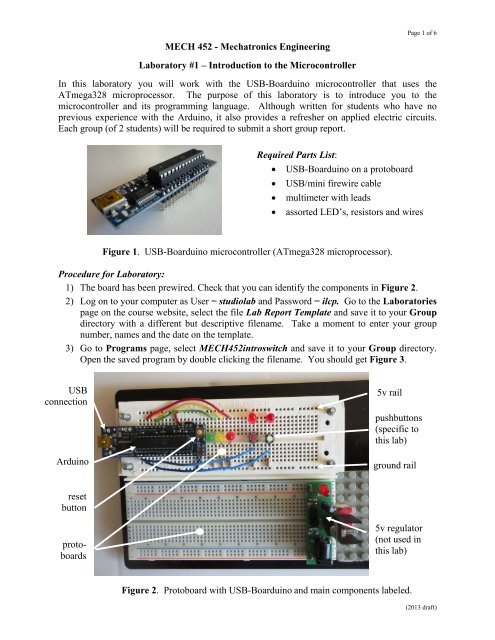
1) The board has been prewired. Check that you can identify <strong>the</strong> components in Figure 2.<br />
2) Log on <strong>to</strong> your computer as User = studiolab and Password = ilcp. Go <strong>to</strong> <strong>the</strong> Labora<strong>to</strong>ries<br />
page on <strong>the</strong> course website, select <strong>the</strong> file Lab Report Template and save it <strong>to</strong> your Group<br />
direc<strong>to</strong>ry with a different but descriptive filename. Take a moment <strong>to</strong> enter your group<br />
number, names and <strong>the</strong> date on <strong>the</strong> template.<br />
3) Go <strong>to</strong> Programs page, select MECH452introswitch and save it <strong>to</strong> your Group direc<strong>to</strong>ry.<br />
Open <strong>the</strong> saved program by double clicking <strong>the</strong> filename. You should get Figure 3.<br />
USB<br />
connection<br />
Arduino<br />
reset<br />
but<strong>to</strong>n<br />
pro<strong>to</strong>-<br />
boards<br />
5v rail<br />
pushbut<strong>to</strong>ns<br />
(specific <strong>to</strong><br />
this lab)<br />
ground rail<br />
5v regula<strong>to</strong>r<br />
(not used in<br />
this lab)<br />
Figure 2. Pro<strong>to</strong>board with USB-Boarduino and main components labeled.<br />
(2013 draft)
Upload<br />
but<strong>to</strong>n<br />
Figure 3. Message when opening file for first time.<br />
Page 2 of 6<br />
4) Click OK, <strong>the</strong> folder MECH452introswitch will be au<strong>to</strong>matically created and <strong>the</strong> Arduino<br />
edi<strong>to</strong>r should open as in Figure 4. Note that <strong>the</strong> background in Figure 4 is white. If <strong>the</strong><br />
background is grey, it means you won’t be able <strong>to</strong> edit. To correct this, go <strong>to</strong> “File” in <strong>the</strong><br />
header, <strong>the</strong>n “Preferences” and <strong>the</strong>n un<strong>to</strong>ggle “Use external edi<strong>to</strong>r”. The background<br />
should switch from grey <strong>to</strong> white (and you will be able <strong>to</strong> edit and save).<br />
5) Confirm that <strong>the</strong> pin assignments in Figure 4 are correct (by checking <strong>the</strong> actual location of<br />
<strong>the</strong> wires relative <strong>to</strong> <strong>the</strong> Arduino pins identified in Figure 5).<br />
Figure 4. Header for <strong>the</strong> MECH452introswitch program in <strong>the</strong> Arduino edi<strong>to</strong>r.<br />
Figure 5. Pin assignments on <strong>the</strong> USB Boarduino.<br />
Serial<br />
moni<strong>to</strong>r<br />
but<strong>to</strong>n
Page 3 of 6<br />
6) Use <strong>the</strong> USB cable <strong>to</strong> connect your computer <strong>to</strong> <strong>the</strong> Arduino. The green (or red) mini-LED <strong>to</strong><br />
<strong>the</strong> right of <strong>the</strong> USB connec<strong>to</strong>r on <strong>the</strong> stack should go steady on, indicating that that you are<br />
receiving power. The red/green mini-LEDs <strong>to</strong> <strong>the</strong> left of <strong>the</strong> USB connec<strong>to</strong>r should flash,<br />
indicating that communication is being tested.<br />
7) Click on <strong>the</strong> arrow but<strong>to</strong>n in <strong>the</strong> header (labeled in Figure 4) <strong>to</strong> upload <strong>the</strong> program <strong>to</strong> <strong>the</strong><br />
Arduino. If you get <strong>the</strong> error message in Figure 6, you may need <strong>to</strong> use <strong>the</strong> Device Manager<br />
on your computer <strong>to</strong> determine <strong>the</strong> number of <strong>the</strong> COM port that is actually in use.<br />
Figure 6. Error message if wrong COM port.<br />
8) Once <strong>the</strong> correct COM port is selected, you may get <strong>the</strong> error message “Wrong<br />
microcontroller found”. To correct this error, go <strong>to</strong> “Tools” in <strong>the</strong> header, <strong>the</strong>n “Board” and<br />
make sure that “Arduino Duemilanove w/ATmega328” has been selected.<br />
9) Once you have <strong>the</strong> correct COM port and <strong>the</strong> correct microcontroller selected, <strong>the</strong>n when you<br />
click on <strong>the</strong> arrow <strong>to</strong> upload, you should see <strong>the</strong> message “Compiling sketch” followed by<br />
<strong>the</strong> message “Done Upload” at <strong>the</strong> bot<strong>to</strong>m of <strong>the</strong> edi<strong>to</strong>r window. When <strong>the</strong> Upload is<br />
complete, <strong>the</strong> Green LED on <strong>the</strong> pro<strong>to</strong>board should flash, indicating that <strong>the</strong> program is<br />
waiting for a but<strong>to</strong>n push <strong>to</strong> start <strong>the</strong> program.<br />
10) Click on <strong>the</strong> serial moni<strong>to</strong>r but<strong>to</strong>n on <strong>the</strong> right side of <strong>the</strong> header (labeled in Figure 4). Note<br />
that this resets <strong>the</strong> program (green LED s<strong>to</strong>ps flashing, mini-LED’s flash, <strong>the</strong>n green LED<br />
restarts). After <strong>the</strong> reset cycle is complete (wait for it, be patient), <strong>the</strong> “debug” window seen<br />
in Figure 7 appears. This window will echo “Serial.println” commands and give feedback <strong>to</strong><br />
<strong>the</strong> user on program status. Make sure that <strong>the</strong> bot<strong>to</strong>m of <strong>the</strong> window shows “9600 baud”.<br />
11) Press <strong>the</strong> reset but<strong>to</strong>n on <strong>the</strong> Arduino (see Figure 2 for location). The message in Figure 7<br />
will repeat itself <strong>to</strong> confirm <strong>the</strong> reset.<br />
Figure 7. Serial moni<strong>to</strong>r window.
12) The operation of <strong>the</strong> program should be as follows:<br />
Page 4 of 6<br />
• green LED on pin P3 flashes ON and OFF once program is loaded<br />
• user presses But<strong>to</strong>n on P9 (white but<strong>to</strong>n) <strong>to</strong> start program cycle<br />
• green/yellow/red LED's on pins P5/P4/P3 flash ON and OFF sequentially<br />
• user presses But<strong>to</strong>n on P8 (red but<strong>to</strong>n) <strong>to</strong> s<strong>to</strong>p program<br />
• green/yellow LED pins P5/P4 flash ON and OFF <strong>to</strong>ge<strong>the</strong>r, red LED pin 3 solid ON<br />
Pressing <strong>the</strong> reset but<strong>to</strong>n on <strong>the</strong> Stack will restart <strong>the</strong> program<br />
13) Experiment with <strong>the</strong> program and <strong>the</strong> circuit, and answer <strong>the</strong> following questions:<br />
a) Measure <strong>the</strong> voltage between <strong>the</strong> vertical rails on <strong>the</strong> pro<strong>to</strong>board and confirm that its<br />
close <strong>to</strong> 5v. Note that this supply is taken from <strong>the</strong> Vcc and Gnd pins on Arduino.<br />
b) For <strong>the</strong> Red LED circuit (<strong>the</strong> one connected <strong>to</strong> Pin 3):<br />
i) Measure <strong>the</strong> voltage across <strong>the</strong> LED when it is solid ON (see Figure 9 for<br />
recommended way, namely with jumper wires). Find a website reference that<br />
confirms this is <strong>the</strong> expected voltage (and cite <strong>the</strong> address in your report).<br />
ii) Measure <strong>the</strong> resistance of <strong>the</strong> 470 Ω resis<strong>to</strong>r (see Figure 10 for recommended way).<br />
Why is it important <strong>to</strong> remove <strong>the</strong> resis<strong>to</strong>r before measuring ? (ie. what’s <strong>the</strong> point<br />
that Figure 10 is trying <strong>to</strong> make?) Find a website reference that confirms <strong>the</strong> colour<br />
coding and <strong>the</strong> <strong>to</strong>lerance for <strong>the</strong> resis<strong>to</strong>r (cite address of website, report colour coding,<br />
comment on whe<strong>the</strong>r within <strong>to</strong>lerance).<br />
iii) Measure <strong>the</strong> voltage across <strong>the</strong> 470 Ω resis<strong>to</strong>r, when <strong>the</strong> Red LED is solid ON.<br />
Calculate <strong>the</strong> current with Ohm’s law and report <strong>the</strong> value.<br />
iv) Measure <strong>the</strong> current when <strong>the</strong> Red LED is solid ON (see Figure 11 for recommended<br />
way, namely move one of <strong>the</strong> LED leads <strong>to</strong> ano<strong>the</strong>r row, and use jumpers on <strong>the</strong><br />
multimeter <strong>to</strong> complete <strong>the</strong> circuit). Does <strong>the</strong> measured current match that calculated<br />
in <strong>the</strong> previous step ? Is it within measurement error ?<br />
v) If <strong>the</strong> maximum recommended output for a pin is 20 mA, what is <strong>the</strong> smallest resis<strong>to</strong>r<br />
that <strong>the</strong> 470 Ω resis<strong>to</strong>r could be replaced with, according <strong>to</strong> Ohm’s law? You can<br />
assume <strong>the</strong> same voltage drop across <strong>the</strong> LED as measured in i) above. Find a<br />
website reference that confirms (or not) <strong>the</strong> maximum output (and cite <strong>the</strong> address in<br />
your report).<br />
c) What is <strong>the</strong> purpose of <strong>the</strong> 470 Ω and 2 KΩ resis<strong>to</strong>rs in <strong>the</strong> circuit of Figure 8 ? Is <strong>the</strong>re<br />
any significance in <strong>the</strong> fact that <strong>the</strong>y are different ?<br />
d) Measure <strong>the</strong> resistance of <strong>the</strong> 2 KΩ resis<strong>to</strong>r. Confirm that its value according <strong>to</strong> its<br />
colour coding is not 2 KΩ (use website from c) above). Is this a problem ?<br />
e) What happens if you reverse any of <strong>the</strong> LED's ? Why does this happen ?<br />
f) Pins 8 and 9 are connected <strong>to</strong> <strong>the</strong> "low" (ground) side of <strong>the</strong> but<strong>to</strong>ns. What happens if<br />
<strong>the</strong>y are connected <strong>to</strong> <strong>the</strong> "high" (5 v) side of <strong>the</strong> but<strong>to</strong>ns ?<br />
g) Make a copy of <strong>the</strong> program MECH452introswitch and rename it Group#introswitch<br />
where # is your group number. Modify <strong>the</strong> program such that only one push but<strong>to</strong>n is<br />
needed <strong>to</strong> start and s<strong>to</strong>p. Don’t forget <strong>to</strong> put your names in <strong>the</strong> header of <strong>the</strong> modified<br />
program. Run <strong>the</strong> program <strong>to</strong> confirm that it still works.
Page 5 of 6<br />
14) To receive credit for this lab, you must demonstrate <strong>to</strong> <strong>the</strong> TA that your (one but<strong>to</strong>n) program<br />
is operating correctly. Finally, you are encouraged <strong>to</strong> complete a draft of <strong>the</strong> report before<br />
leaving <strong>the</strong> lab. Do not disassemble <strong>the</strong> circuit. You will need it for <strong>the</strong> next day (and for<br />
subsequent labs).<br />
Procedure for Tu<strong>to</strong>rial:<br />
The instruc<strong>to</strong>rs have introduced 4 wiring errors <strong>to</strong> your circuit that you had working <strong>the</strong> day<br />
before. Identify and correct <strong>the</strong> 4 errors and demonstrate <strong>to</strong> an instruc<strong>to</strong>r that <strong>the</strong> original<br />
program.<br />
Report (due before end of tu<strong>to</strong>rial period)<br />
You are required <strong>to</strong> submit your report as an Adobe (.pdf) file by email <strong>to</strong><br />
mech452.2013@gmail.com. Please use as <strong>the</strong> Adobe filename: “Lab1StampIntroGroupX”<br />
where “X” is your group number and use <strong>the</strong> same name in <strong>the</strong> Subject line of your email. The<br />
report must: a) Summary Section (what did you do and what did you learn ?), b) Answers<br />
Section (answers <strong>to</strong> questions of Step 13) and c) Appendix Section (listing of<br />
Group#introswitch, with additions or changes from original MECH452introswitch highlighted<br />
(eg. by colouring changes in Word).<br />
Marks will be deducted for <strong>the</strong> following format errors: a) incorrect filename, b) incorrect email<br />
Subject, c) no student names in header of program listing.<br />
GREEN<br />
Pin 5 Pin 4 Pin 3<br />
YELLOW<br />
RED<br />
RED RED<br />
Figure 8. Circuits for Lab #1.<br />
Pin 8 Pin 9
Figure 9. Measurement of voltage across Red LED.<br />
Figure 10. Measurement of resis<strong>to</strong>r resistance.<br />
Figure 11. Measurement of current in Red LED circuit.<br />
Page 6 of 6