Chonkar R. R..p65 - The Indian Concrete Journal
Chonkar R. R..p65 - The Indian Concrete Journal
Chonkar R. R..p65 - The Indian Concrete Journal

You also want an ePaper? Increase the reach of your titles
YUMPU automatically turns print PDFs into web optimized ePapers that Google loves.
Point of View<br />
Review of design of reinforced earth<br />
retaining walls for flyovers<br />
R.R. R.R. <strong>Chonkar</strong><br />
<strong>Chonkar</strong><br />
Among several innovative construction techniques,<br />
new materials of constructions and<br />
new technologies adopted in the construction<br />
of flyovers in Mumbai by Maharashtra<br />
State Road Development Corporation<br />
(MSRDC), the reinforced earth technique<br />
has definitely proved the advantages of this<br />
technology over conventional reinforced<br />
concrete (RC) retaining walls both in terms<br />
of saving foundation cost, working space<br />
and time.<br />
<strong>The</strong> reinforced earth technology is in use<br />
in the west, especially in Great Britain and<br />
France, for the last 35 years or so. British<br />
Standards Institute and French Standards<br />
have also come out with codes of practice<br />
covering this technique containing<br />
guidelines and recommendations for design<br />
and construction of reinforced earth<br />
technique, vide BS 8006:1995 and NF P 94-<br />
220, in 1992. <strong>The</strong> <strong>Indian</strong> Roads Congress -<br />
Highway Research Board, published a<br />
Special Report No. 16 (SR-16) “State-ofthe-art<br />
reinforced soil structures applicable<br />
to road design and construction” in 1996.<br />
<strong>The</strong> Department of Transport, UK, has also<br />
published the recommended design criteria<br />
in the Technical Memorandum (BR) BE-3/78.<br />
Background<br />
Basically, there are two commonly used reinforcing<br />
materials: one metallic, and the<br />
Mr R.R. <strong>Chonkar</strong>, Consulting Engineer, Mumbai.<br />
other polymeric. <strong>The</strong> Terre Armee International<br />
– (group TAI) is credited with the<br />
invention and development of reinforced<br />
earth technology and carried out their first<br />
major work as early as 1968 and are since<br />
then the holders of the patent filed by Henri<br />
Vidal, the inventor of the reinforced earth<br />
technique. In India Aimil Ltd are the licensees<br />
of this technology<br />
and have executed<br />
the first reinforced<br />
earth retaining<br />
wall at the<br />
Jammu arterial expressway<br />
and<br />
since then successfully<br />
carried out reinforced<br />
earth retaining<br />
walls for<br />
the ramps of a<br />
couple of flyovers<br />
recently constructed.<br />
Soil retaining<br />
technique has several<br />
applications<br />
like simple retaining<br />
walls, abutment<br />
for bridges,<br />
high embankment,<br />
slope stabilisation,<br />
etc. It basically involvesincorporating<br />
reinforcement<br />
in earth / fills to<br />
<strong>The</strong>se columns of ICJ offer an opportunity to the<br />
engineering fraternity to express their views on the<br />
current practices in design, construction and<br />
management being followed in the industry.<br />
To share your opinion with our readers, you may send<br />
in your inputs in about 1500 words via E-mail to<br />
editor@icjonline.com<br />
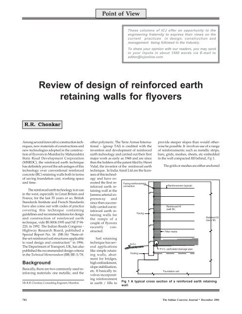
provide steeper slopes than would otherwise<br />
be possible. It involves use of a range<br />
of reinforcements; such as metallic strips,<br />
bars, grids, meshes, sheets, etc embedded<br />
in the well compacted fill behind, Fig 1.<br />
<strong>The</strong> grids or meshes are either anchored<br />
Fig 1 A typical cross section of a reinforced earth retaining<br />
wall<br />
782 <strong>The</strong> <strong>Indian</strong> <strong>Concrete</strong> <strong>Journal</strong> * December 2001
Fig 2 Reinforced earth system with metallic strips,<br />
licencees: Aimil Ltd<br />
in facia panels or wrap around, the latter<br />
especially in case of polymeric<br />
reinforcement. <strong>The</strong> reinforcement improves<br />
the behaviour of the fill both at service<br />
condition and the failure stage.<br />
MSRDC has used both types of<br />
reinforcements, that is, metallic and<br />
polymeric. In India there are two agencies<br />
who use metallic reinforcement, namely,<br />
Aimil Ltd in a joint venture with group TAI<br />
for reinforced earth technology and MBN<br />
anchored earth Ltd of Hyderabad, who are<br />
representatives of Anchored Earth Sdn Bhd<br />
of Malaysia for the Anchored Earth<br />
technique. <strong>The</strong> basic difference in these two<br />
systems is the manner in which the force<br />
exerted by soil is resisted by embedded<br />
reinforcement.<br />
In the case of anchored earth system<br />
this is provided by the passive action of<br />
anchors and friction along the perimeter of<br />
anchor shaft or reinforcement. In reinforced<br />
earth technology, only friction is taken<br />
advantage of by providing specially<br />
Fig 3 Anchored earth system with metallic bars and<br />
anchor blocks, licencees: MBN Anchored Earth Ltd<br />
December 2001 * <strong>The</strong> <strong>Indian</strong> <strong>Concrete</strong> <strong>Journal</strong><br />
Point of View<br />
prepared high adherence galvanised steel<br />
strips as reinforcement, Figs 2 and 3. Both<br />
these processes use precast panels as facia<br />
elements, the shapes being different, Fig 4.<br />
Design philosophy<br />
Fig 4 Nehemiah AE wall panels<br />
As far as design is concerned both adopt<br />
the provisions of BS 8006; adopting limit<br />
state method with partial safety factors and<br />
check for ‘external stability’ and ‘internal<br />
stability’. <strong>The</strong> IRC has not yet revised their<br />
codes to suit limit state method and continues<br />
to design roads/ bridge structures<br />
using the working stress method, with the<br />
factor of safety approach; the sample calculations<br />
of solved examples presented in<br />
Special Report No. 16 are based on the<br />
working stress method.<br />
MSRDC in their first tenders for flyovers<br />
in 1997 stipulated that design of reinforced<br />
earthwork shall be in accordance with the<br />
ministry of surface transport (MOST)<br />
specifications and guidelines contained in<br />
IRC Special Report No. 16. Aimil Ltd, the<br />
Fig 5 Reinforced earth wall<br />
<strong>Indian</strong> counterpart of TAI group then had<br />
no full fledged technical wing conversant<br />
with reinforced earth wall design and<br />
therefore the design calculations for their<br />
first work of flyover at Aarey junction on<br />
the western express highway in Mumbai<br />
was prepared using a computer<br />
programme available with their French<br />
counterpart. This was based on the limit<br />
state design philosophy, confirming to BS<br />
8006. It was therefore required to revise<br />
these calculations to suit working stress<br />
method and conforming to various practices<br />
and codes published by <strong>Indian</strong> Roads<br />
Congress. This was done by project<br />
management consultants (PMC)—<br />
Technogem Consultants, Mumbai, in<br />
association with engineers of Aimil, India.<br />
While doing this it was necessary to<br />
revise various values of engineering<br />
properties of the soil stipulated in BS:8006<br />
as per the actual material proposed to be<br />
used on the work, after carrying out the<br />
necessary laboratory tests. This was done<br />
after confirming the suitability of source of<br />
783
Point of View<br />
Fig 6 Miragrid Fig 8 Jkar modular facia blocks<br />
murum with respect to availability of<br />
quantum and its suitability for reinforced<br />
earthwork as stipulated in BS 8006 with<br />
respect to electrical resistivity, grading, etc.<br />
Metallic reinforcement<br />
<strong>The</strong> metallic reinforcement was supplied<br />
by Aimil which was manufactured in India<br />
(as per their parent firm as patented). Galvanised<br />
high adherence carbon steel strips<br />
of 140 micron, 40 mm x 5 mm, in class 2<br />
steel as per IS : 1875, with minimum ultimate<br />
tensile strength (UTS) of 490 N/mm 2<br />
were supplied. For facia panels Aimil supplied<br />
samples of forms adopted by them in<br />
their work at Jammu. Additional forms<br />
were prepared after carrying out some<br />
modifications in front appearance and panel<br />
casting was done by Aimil through<br />
Prestressing Corporation of India, factory<br />
at Kalamboli (near Panvel about 30 km<br />
away from the work site). <strong>The</strong> various fasteners<br />
required to be embedded in facia<br />
panels, joint materials like EPDM pads,<br />
foam strips, etc. were supplied by Aimil.<br />
<strong>The</strong> scope of work included erection of<br />
walls, installation of strips using labour and<br />
machinery, which was provided by the principal<br />
contractors, Simplex <strong>Concrete</strong> Piles<br />
(I) Ltd, and day-to-day supervision of the<br />
work of backfilling and compaction carried<br />
out by other agencies.<br />
Besides a change in the design<br />
philosophy, MSRDC stipulated loading<br />
confirming to IRC Codes, that is, 1.2-m high<br />
live load surcharge effect, provision of crash<br />
barriers as per type P6; design life of 120<br />
years; minimum depth of foundation of<br />
1000 mm below ground level; zinc<br />
galvanised with 1000 g / m 2 . <strong>The</strong> external<br />
and internal stability should yield<br />
minimum factor of safety of 1.5 under<br />
service condition.<br />
During scrutiny it was revealed that the<br />
value of μ, the coefficient of friction between<br />
the fill and high adherence strips, adopted<br />
by Aimil, took into consideration interaction<br />
coefficient relating to soil / reinforcement<br />
bond angle (BS 8006) obtained from pull-<br />
out test, linearly varying from maximum<br />
at top to uniform value of tan φ at the<br />
critical depth of 6 m. <strong>The</strong> maximum value<br />
of friction between high adherence strips<br />
and backfill soil as given in French<br />
Standards NF P 94 – 220 and incorporated<br />
in SR – 16 is<br />
μ* = 1.2 + log C u<br />
784 <strong>The</strong> <strong>Indian</strong> <strong>Concrete</strong> <strong>Journal</strong> * December 2001<br />
where,<br />
C u = (D60/D10) = Coefficient of<br />
homogeneity of back fill material which is 2<br />
(minimum) as required for soil to be<br />
suitable for reinforced earth walls.<br />
<strong>The</strong> documentary evidence of the above<br />
assumption was considered as not<br />
sufficient. Moreover, Aimil had not carried<br />
out any pull-out test either in the field or<br />
laboratory in India as stipulated in BS-8006.<br />
Results of pull out tests carried out by Aimil<br />
outside India were not accepted by PMC<br />
who insisted on restricting the value of<br />
μ = tan δ, where δ is angle of friction between<br />
Fig 7 Tensar geogrid Fig 9 Reinforced wall construction for Kalamboli flyover
the reinforcement material and the soil. As<br />
per practice, the value of δ is restricted to<br />
2/3 φ, the angle of internal friction of the<br />
soil. <strong>The</strong> variation between the μ value at<br />
top and critical depth was accepted.<br />
Observations have indicated that earth<br />
pressure near the top is pressure at rest<br />
because compaction at top is more effective.<br />
<strong>The</strong> maximum and minimum value of μ<br />
was assumed as equal to tan (2/3 φa) and<br />
tan (2/3 φc), where φa is peak value and<br />
φc is critical value of angle of internal<br />
friction. <strong>The</strong> engineers from Aimil accepted<br />
this argument and allowed the PMC to<br />
revise the design accordingly.<br />
This issue was further discussed at large<br />
in the open forum of the national workshop<br />
held in Mumbai on “Reinforced soil retaining<br />
walls” in November 1998 1 . However, no<br />
definite conclusion was arrived at.<br />
Aimil reinforced earth walls are not<br />
provided with separate filter media behind<br />
the facia. Large gaps remain between<br />
panels because of the provision of bearing<br />
pads, for horizontal joints between panels,<br />
made of elastomer with vulcanised EPDM.<br />
<strong>The</strong>se gaps are closed using flexible open<br />
cell polyurethane foam strips or non-woven<br />
fabric strips. MSRDC raised this issue in<br />
the national seminar and called for<br />
discussion. <strong>The</strong> general consensus was in<br />
favour of providing minimum 600 mm<br />
thick filter media of graded aggregate<br />
between facia panels and back fill with<br />
perforated PVC pipe of 200 mm diameter<br />
covered with non-woven geotextile at<br />
bottom, to drain out water collected from<br />
backfill, though this entailed extra cost.<br />
<strong>The</strong> reinforced earth walls so far<br />
constructed using this patented process<br />
have behaved satisfactorily and no<br />
noticeable distress has been observed when<br />
inspected two years later, Fig 5.<br />
Anchored earth system<br />
MBN anchored earth system has also been<br />
tried for flyovers constructed in Mumbai<br />
and Hyderabad. <strong>The</strong>re is no much difference<br />
in design involving checks for external<br />
and internal stability. <strong>The</strong> point of argument<br />
is whether friction capacity can be<br />
considered to co-existent with anchorage<br />
capacity, as friction more or less reduces<br />
after movement of strip and later needs<br />
large movement of anchor blocks to generate<br />
the design being based on failure condition.<br />
Recent specifications and design chapter<br />
now under consideration with MSRDC<br />
have modified these provisions of BS 8006.<br />
<strong>The</strong> other provision of BS-8006 not consistent<br />
with classical theory is ultimate value<br />
December 2001 * <strong>The</strong> <strong>Indian</strong> <strong>Concrete</strong> <strong>Journal</strong><br />
Point of View<br />
of passive pressure; the one stipulated in<br />
equation vide clause 6.6.4.2.3 of BS 8006 :<br />
1995 which is reproduced below.<br />
Anchored earth: <strong>The</strong>re are a variety of different<br />
anchored earth systems. <strong>The</strong> tensile<br />
forces generated in the anchor should be<br />
calculated in accordance with a 6.6.4.2.1<br />
Local stability in terms of rupture should<br />
be considered in accordance with clause<br />
6.6.4.2.2 or a 6.6.5.2.5. <strong>The</strong> pull-out capacity<br />
of anchor reinforcing elements to satisfy<br />
local stability consideration is:<br />
P uj<br />
³<br />
f<br />
p<br />
f<br />
n<br />
T<br />
j<br />
where,<br />
P = ultimate pull-out<br />
uj<br />
resistance of the anchor<br />
ƒ = partial factor for<br />
p<br />
reinforcement pull-out<br />
resistance, see Table 16<br />
ƒ = partial factor applied to<br />
n<br />
economic ramifications of<br />
failure, see Table 3;<br />
T = maximum value of the th<br />
j<br />
j<br />
level of reinforcement<br />
from clause 6.6.4.2.1.<br />
<strong>The</strong> ultimate pull-out resistance of an<br />
anchor element in the th layer may be<br />
j<br />
determined from :<br />
where,<br />
Puj Psj P aj<br />
P sj<br />
= P + P sj aj<br />
= 2μB s L s vj ej<br />
= 4 K p B a t a σ vj<br />
= shaft or loop resistance<br />
developed by friction<br />
beyond the potential<br />
failure plane, at the th j<br />
layer of anchors;<br />
= bearing resistance at the<br />
th layer of anchors;<br />
j<br />
μ = coefficient of soil /<br />
reinforcement friction and<br />
is determined according<br />
to the relationship given in<br />
clause 6.6.4.2.2;<br />
= long term horizontal<br />
projection area of shaft or<br />
loop;<br />
= horizontal passive earth<br />
pressure coefficient;<br />
= long term width of anchor<br />
head;<br />
= long term height of anchor<br />
P aj<br />
B s<br />
K p<br />
B a<br />
t a<br />
head;<br />
σ = vertical applied pressure<br />
vj<br />
at the th layer of anchors;<br />
j<br />
L = length of the anchor shaft<br />
ej<br />
beyond the potential<br />
failure plane.<br />
Grouted anchor elements should be<br />
treated as ground anchors and the ultimate<br />
pull-out resistance should be determined<br />
from the relations given in BS 8081.<br />
Polymeric reinforcement<br />
Not only the French, but the department of<br />
transport, U.K.- BE 3/78 accepted the use<br />
of geo-textile as reinforcement in soil reinforced<br />
structures. <strong>The</strong> IRC SR-16 and standard<br />
specifications for road/bridges allow<br />
use of geo-textile made from synthetic polymers<br />
using polyethylene, polyamides, polyester,<br />
polypropylene; woven, non-woven or<br />
extruded bi-axial or uni-axial grids, sheets,<br />
etc, for reinforced fill/soil walls.<br />
MSRDC has used all the above types of<br />
geo-textile as reinforcement for retaining<br />
walls along flyover ramps and even behind<br />
abutment piers, though load bearing<br />
abutment proper have not so far been tried<br />
using this technology. As of today geogrids<br />
suitable for reinforced soil are not<br />
manufactured in India; most of geo-textiles<br />
and geogrids used so far in civil engineering<br />
works like Kologrid, Miragrid, Fortrac or<br />
Tensar are imported from abroad. All these<br />
varieties have been used in flyover ramps<br />
or reinforced walls, Figs 6 and 7.<br />
Differences<br />
<strong>The</strong> design method and approach remain<br />
the same as for metallic reinforcement with<br />
regards to check for external stability and<br />
internal stability for pull-out and tension.<br />
Most of the soil reinforcement wall so far<br />
constructed using geosynthetics have used<br />
concrete precast blocks as facia element,<br />
Fig 8.<br />
Precast panels have been used<br />
exceptionally in the case of reinforced wall<br />
constructed for Kalamboli flyover between<br />
flyover proper and road over bridge. <strong>The</strong><br />
height of this wall is more than 10 m,<br />
Fig 9.<br />
Unlike metallic reinforcement, which is<br />
inextensible with very low strain value (less<br />
than one percent as per BS 8006), polymeric<br />
reinforcement has high strains greater than<br />
one percent reaching peak value as high as<br />
15 percent including creep effect under<br />
maximum stress. Moreover, the creep value<br />
of polypropylene and polyethylene grids are<br />
785
higher. Both the strain and creep values are<br />
time dependent and also depend upon the<br />
temperature of the fill material. <strong>The</strong> use of<br />
geosynthetics for civil engineering purpose,<br />
particularly for soil reinforcement is of<br />
recent origin. <strong>The</strong> long term effects of stress,<br />
temperature, creep, etc, are extrapolated<br />
values from short term tests and therefore<br />
have to be cautiously used with appropriate<br />
values of partial safety factors.<br />
<strong>The</strong> environmental effects, biological<br />
effects, fill material, damage factor, effect<br />
of construction method, joint efficiency, etc,<br />
are all based on western conditions and<br />
western practice of quality assurance<br />
schemes, which are definitely different from<br />
<strong>Indian</strong> conditions with respect to material,<br />
labour and quality control. <strong>The</strong>refore the<br />
values suggested by manufacturers need<br />
to be vetted properly before using the same<br />
in our designs. Some of the initially<br />
constructed reinforced walls using geogrids<br />
have behaved differently from what was<br />
expected during design. Especially in<br />
Mumbai and coastal regions where total<br />
Point of View<br />
rainfall and intensity of rainfall is high and<br />
backfill material not consistent, the design<br />
using geogrid as reinforcement has to have<br />
an extra factor of safety.<br />
<strong>The</strong> main drawback experienced in the<br />
use of geogrid is that there are no accredited<br />
laboratories in India where one can carry<br />
out even a simple tensile strength test, leave<br />
alone creep or long term strength values<br />
and isochronous curves, damage factor,<br />
u-v effect, chemical effects, biological<br />
effects etc. <strong>The</strong> designer therefore has to<br />
rely on manufacturers’ literature and accept<br />
the values, tested either in their laboratories<br />
or internationally accredited laboratories<br />
under western conditions and<br />
workmanship.<br />
Since the number of segment for facia<br />
are large, in case of precast blocks,<br />
compared to panels, it is very difficult to<br />
obtain consistent results with respect to<br />
finish, strength, colour and sharpness, and<br />
to maintain time schedule. <strong>The</strong> imported<br />
block making machines being very few,<br />
locally manufactured machines were<br />
extensively used which gives rise to large<br />
number of rejections of precast blocks<br />
hampering the time schedule of work. <strong>The</strong><br />
skilled labour required for block work is<br />
also more when compared to cranes used<br />
for errection of facia panels, which gives<br />
rise to inconsistency in work with respect to<br />
finish, workmanship and output.<br />
Conclusion<br />
Mere short-term performance for a couple<br />
of years is not sufficient to infuse confidence<br />
in the minds of engineers in India<br />
and till we observe the performance of walls<br />
for at least 10 years or so (design life being<br />
120 years), we have to be careful in design<br />
and should be extra cautious in selecting<br />
partial safety factors, load factors and factors<br />
of safety.<br />
References<br />
1. ______National workshop on "Reinforced soil<br />
retaining walls", Mumbai, November 1998,<br />
<strong>Indian</strong> Institution of Bridge Engineers.<br />
•••<br />
786 <strong>The</strong> <strong>Indian</strong> <strong>Concrete</strong> <strong>Journal</strong> * December 2001