

POSITIP 855 - heidenhain - DR. JOHANNES HEIDENHAIN GmbH
POSITIP 855 - heidenhain - DR. JOHANNES HEIDENHAIN GmbH
POSITIP 855 - heidenhain - DR. JOHANNES HEIDENHAIN GmbH

You also want an ePaper? Increase the reach of your titles
YUMPU automatically turns print PDFs into web optimized ePapers that Google loves.
I - 1 Fundamentals of Positioning<br />
Fundamentals of Positioning<br />
Position feedback<br />
The position feedback encoders convert the movement of the machine<br />
axes into electrical signals. The <strong>POSITIP</strong> constantly evaluates<br />
these signals and calculates the actual positions of the machine<br />
axes, which it displays as a numerical value on the screen.<br />
If there is an interruption in power, the calculated position will no<br />
longer correspond to the actual position. When power is restored,<br />
you can re-establish this relationship with the aid of the reference<br />
marks on the position encoders and the <strong>POSITIP</strong>'s reference mark<br />
evaluation feature (REF).<br />
Reference marks<br />
The scales of the position encoders contain one or more reference<br />
marks. When a reference mark is passed over, it generates a signal<br />
which identifies that position as the reference point (scale reference<br />
point = machine reference point). With the aid of this reference<br />
mark the <strong>POSITIP</strong>'s REF feature re-establishes the assignment of<br />
displayed positions to machine axis positions which you last defined<br />
by setting the datum.<br />
If the position encoders feature distance-coded reference marks,<br />
each axis needs only move a maximum of 20 mm (0.8 in.) for linear<br />
encoders, and 20° for angle encoders.<br />
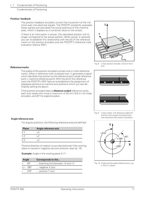
Angle reference axis<br />
For angular positions, the following reference axes are defined:<br />
Plane Angle reference axis<br />
X Y +X<br />
Y Z +Y<br />
Z X +Z<br />
Positive direction of rotation is counterclockwise if the working<br />
plane is viewed in negative tool axis direction (see fig. 10).<br />
Example: Angle in the working plane X / Y<br />
Angle Corresponds to the...<br />
+ 45° ... bisecting line between +X and +Y<br />
+/– 180° ... negative X axis<br />
– 270° ... positive Y axis<br />
Fig. 8: Linear position encoder, here for the X<br />
axis<br />
Fig. 9: Linear scales: with distance-coded reference<br />
marks (upper illustration) and<br />
one reference mark (lower illustration)<br />
<strong>POSITIP</strong> <strong>855</strong> Operating Instructions 11<br />
Y<br />
Z<br />
–270°<br />
Y<br />
+45°<br />
+180°<br />
–180°<br />
Fig. 10: Angle and the angle reference axis, e.g.<br />
in the X / Y plane<br />
X<br />
X


