Aerogeophysics in Finland 1972-2004 - arkisto.gsf.fi - Geologian ...
Aerogeophysics in Finland 1972-2004 - arkisto.gsf.fi - Geologian ...
Aerogeophysics in Finland 1972-2004 - arkisto.gsf.fi - Geologian ...

Create successful ePaper yourself
Turn your PDF publications into a flip-book with our unique Google optimized e-Paper software.
Tätä julkaisua myy Denna publikation säljes av This publication can be obta<strong>in</strong>ed<br />
from<br />
GEOLOGIAN GEOLOGISKA GEOLOGICAL SURVEY<br />
TUTKIMUSKESKUS (GTK) FORSKNINGSCENTRALEN (GTK) OF FINLAND (GTK)<br />
Julkaisumyynti Publikationsförsäljn<strong>in</strong>g Publication sales<br />
PL 96 PB 96 P.O. Box 96<br />
02151 Espoo 02151 Esbo FI-02151 Espoo, F<strong>in</strong>land<br />
020 550 11 020 550 11 +358 20 550 11<br />
Telekopio: 020 550 12 Telefax: 020 550 12 Telefax: +358 20 550 12<br />
GTK, Itä-Suomen yksikkö GTK, Östra F<strong>in</strong>lands enhet GTK, Eastern F<strong>in</strong>land Of<strong>fi</strong>ce<br />
Kirjasto Biblioteket Library<br />
PL 1237 PB 1237 P.O. Box 1237<br />
70211 Kuopio 70211 Kuopio FI-70211 Kuopio, F<strong>in</strong>land<br />
020 550 11 020 550 11 +358 20 550 11<br />
Telekopio: 020 550 13 Telefax: 020 550 13 Telefax: +358 20 550 13<br />
GTK, Pohjois-Suomen yksikkö GTK, Norra F<strong>in</strong>lands enhet GTK, Northern F<strong>in</strong>land Of<strong>fi</strong>ce<br />
Kirjasto Biblioteket Library<br />
PL 77 PB 77 P.O. Box 77<br />
96101 Rovaniemi 96101 Rovaniemi FI-96101 Rovaniemi, F<strong>in</strong>land<br />
020 550 11 020 550 11 +358 20 550 11<br />
Telekopio: 020 550 14 Telefax: 020 550 14 Telefax: +358 20 550 14<br />
E-mail: julkaisumyynti@gtk.<strong>fi</strong> ISBN 951-690-916-7<br />
WWW-address: www.gtk.<strong>fi</strong> ISSN 0782-8535<br />
9 789516 909151<br />
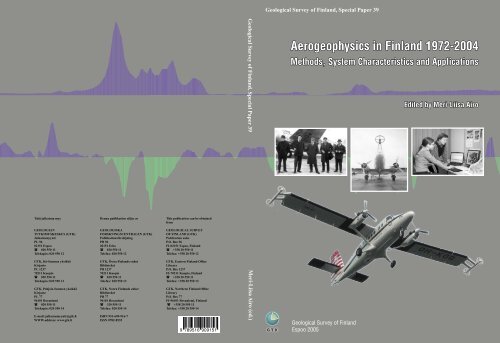
Geological Survey of F<strong>in</strong>land, Special Paper 39 Meri-Liisa Airo (ed.)<br />
Geological Survey of F<strong>in</strong>land, Special Paper 39<br />
<strong>Aerogeophysics</strong> <strong>in</strong> F<strong>in</strong>land <strong>1972</strong>-<strong>2004</strong><br />
Methods, System Characteristics and Applications<br />
Geological Survey of F<strong>in</strong>land<br />
Espoo 2005<br />
Edited by Meri-Liisa Airo
Geological Survey of F<strong>in</strong>land, Special Paper 39<br />
<strong>Aerogeophysics</strong> <strong>in</strong> F<strong>in</strong>land <strong>1972</strong>–<strong>2004</strong><br />
Methods, System Characteristics and Applications<br />
edited by Meri-Liisa Airo<br />
Geological Survey of F<strong>in</strong>land<br />
Espoo 2005
Airo, Meri-Liisa (ed.) 2005. <strong>Aerogeophysics</strong> <strong>in</strong> F<strong>in</strong>land <strong>1972</strong>–<strong>2004</strong>:<br />
Methods, System Characteristics and Applications. Geological Survey of<br />
F<strong>in</strong>land, Special Paper 39. 197 pages, 115 <strong>fi</strong>gures, 12 tables and<br />
8 appendices.<br />
Key words (GeoRef Thesaurus, AGI): geophysical methods, airborne<br />
methods, magnetic methods, electromagnetic methods, gamma-ray methods,<br />
applications, m<strong>in</strong>eral exploration, environmental geology, F<strong>in</strong>land<br />
Meri-Liisa Airo<br />
Geological Survey of F<strong>in</strong>land<br />
P.O. Box 96<br />
FI-02151 Espoo<br />
F<strong>in</strong>land<br />
E:mail: meri-liisa.airo@gtk.<strong>fi</strong><br />
ISBN 951-690-915-9<br />
ISSN 0782-8535<br />
Vammalan Kirjapa<strong>in</strong>o Oy 2005
CONTENTS<br />
Geological Survey of F<strong>in</strong>land, Special Paper 39<br />
<strong>Aerogeophysics</strong> <strong>in</strong> F<strong>in</strong>land <strong>1972</strong>–<strong>2004</strong> Otsikko<br />
Methods, System Characteristics and Applications<br />
Editor’s preface ....................................................................................................... 4<br />
Methods ................................................................................................................... 5<br />
Airborne Geophysics <strong>in</strong> F<strong>in</strong>land <strong>in</strong> Perspective, Markku Peltoniemi ................. 7<br />
The “Three In One” aerogeophysical concept of GTK <strong>in</strong> <strong>2004</strong>, Heikki Hautaniemi,<br />
Maija Kurimo, Jukka Multala, Hanna Leväniemi and Jouko Vironmäki 21<br />
System characteristics ............................................................................................. 75<br />
Airborne Magnetic Method: Special Features and Review on Applications,<br />
Juha Korhonen .................................................................................................... 77<br />
GTK airborne EM system: characteristics and <strong>in</strong>terpretation guidel<strong>in</strong>es, Ilkka<br />
Suppala, Matti Oksama and Hannu Hongisto .................................................... 103<br />
Airborne Gamma-ray Surveys <strong>in</strong> F<strong>in</strong>land, Eija Hyvönen, Pertti Turunen, Erkki<br />
Vanhanen, Hilkka Arkimaa and Raimo Sut<strong>in</strong>en .................................................. 119<br />
Applications............................................................................................................. 135<br />
Application of low altitude airborne geophysics to m<strong>in</strong>eral exploration <strong>in</strong> the<br />
Kuusamo schist belt, F<strong>in</strong>land, Pertti Turunen, Erkki Vanhanen and Heikki<br />
Pankka ................................................................................................................. 137<br />
Geophysical Investigation of Kaol<strong>in</strong> and Ilmenite Deposits <strong>in</strong> F<strong>in</strong>land,<br />
Jaana Lohva and Jukka Lehtimäki ...................................................................... 147<br />
Environmental applications of airborne geophysics – groundwater and<br />
contam<strong>in</strong>ated soil <strong>in</strong> F<strong>in</strong>land, Germany and United K<strong>in</strong>gdom, Mari Lahti,<br />
Heikki Vanhala, Ann<strong>in</strong>a Mattsson, David Beamish and Jouni Lerssi................. 155<br />
Regional <strong>in</strong>terpretation of aerogeophysical data: extract<strong>in</strong>g compositional and<br />
structural features, Meri-Liisa Airo..................................................................... 176<br />
3
Geological Survey of F<strong>in</strong>land, Special Paper 39<br />
Meri-Liisa Airo (ed.)<br />
4<br />
EDITOR’S PREFACE<br />
S<strong>in</strong>ce <strong>1972</strong> the Geological Survey of F<strong>in</strong>land (GTK) has conducted extremely high-resolution<br />
airborne geophysical surveys, which soon cover the whole country. Through all these years,<br />
there has been a strong need for a summariz<strong>in</strong>g report expla<strong>in</strong><strong>in</strong>g the airborne system and its<br />
specialities, but the operational works and demands have prevented the concentrat<strong>in</strong>g to writ<strong>in</strong>g.<br />
The 50 year-anniversary of aerogeophysical surveys <strong>in</strong> F<strong>in</strong>land gave the <strong>fi</strong>rst idea of publish<strong>in</strong>g<br />
the development of the aerogeophysical 3-<strong>in</strong>-1 system. Secondly, the f<strong>in</strong>ish<strong>in</strong>g of the airborne<br />
mapp<strong>in</strong>g program <strong>in</strong> F<strong>in</strong>land <strong>in</strong> its present form, and thirdly, that the beg<strong>in</strong>n<strong>in</strong>g of the new<br />
airborne concept of co-operation with the British Geological Survey (BGS) will change the<br />
aerogeophysical concept <strong>in</strong> some extent, have pushed forward understand<strong>in</strong>g of the importance<br />
of collect<strong>in</strong>g the experimental and operational experiences <strong>in</strong> one volume.<br />
The contents of this volume are divided <strong>in</strong>to three parts, which highlight the history,<br />
development and the present state of the techniques, the speci<strong>fi</strong>c system characteristics and<br />
their theoretical background, and a wide range of possible applications <strong>in</strong> <strong>in</strong>terpretation of the<br />
multi-property airborne data. The authors are experts <strong>in</strong> aerogeophysical surveys and<br />
<strong>in</strong>terpretation. In particular, we want to give an idea of the theory beh<strong>in</strong>d and the characteristics<br />
of the GTK electromagnetic <strong>fi</strong>xed-w<strong>in</strong>g frequency doma<strong>in</strong> system, which is quite unique<br />
worldwide. Further, experience <strong>in</strong> conduct<strong>in</strong>g and <strong>in</strong>terpret<strong>in</strong>g systematic airborne gamma-ray<br />
measurements are another <strong>in</strong>terest<strong>in</strong>g question to be <strong>in</strong>troduced.<br />
We own this volume to the pioneers <strong>in</strong> aerogeophysical work and all those who were <strong>in</strong> dur<strong>in</strong>g<br />
these years. We also acknowledge the airborne organizations for their contribution <strong>in</strong> production<br />
and development of the measur<strong>in</strong>g process. We thank all the reviewers of the articles, <strong>in</strong> GTK<br />
and outside, for their <strong>in</strong>put ref<strong>in</strong><strong>in</strong>g the manuscripts. We also thank the technical editors S<strong>in</strong>i<br />
Autio and Eila Karhu for their hard work, and Christopher Cunliffe who made the English<br />
check<strong>in</strong>g.<br />
Espoo 2.10.2005<br />
Meri-Liisa Airo
Geological Survey of F<strong>in</strong>land, Special Paper 39<br />
Markku Peltoniemi<br />
<strong>Aerogeophysics</strong> <strong>in</strong> F<strong>in</strong>land <strong>1972</strong>–<strong>2004</strong>:<br />
Methods, System Characteristics and Applications,<br />
edited by Meri-Liisa Airo.<br />
Geological Survey of F<strong>in</strong>land, Special Paper 39, 7–20, 2005.<br />
AIRBORNE GEOPHYSICS IN FINLAND IN PERSPECTIVE<br />
by<br />
Markku Peltoniemi<br />
Peltoniemi, M. 2005. Airborne geophysics <strong>in</strong> F<strong>in</strong>land <strong>in</strong> perspective.<br />
Geological Survey of F<strong>in</strong>land, Special Paper 39, 7–20.<br />
The development and applications of airborne geophysical methods <strong>in</strong><br />
F<strong>in</strong>land are briefly described. Most of the surveys have been carried out by<br />
the Geological Survey of F<strong>in</strong>land, which has been <strong>in</strong>volved <strong>in</strong> the development<br />
and use of the technique s<strong>in</strong>ce the early 1950s and has s<strong>in</strong>ce then<br />
implemented two country-wide mapp<strong>in</strong>g programmes with airborne geophysical<br />
methods. Several different survey aircraft have been used and<br />
several types of geophysical <strong>in</strong>strumentation and data process<strong>in</strong>g systems<br />
have been applied up to the present day. Special attention is focused <strong>in</strong> this<br />
paper on the second programme with high-resolution, low-elevation surveys<br />
s<strong>in</strong>ce <strong>1972</strong>. Such surveys, both for exploration and geological mapp<strong>in</strong>g,<br />
have been conducted <strong>in</strong> F<strong>in</strong>land with the goal to replace geophysical<br />
ground surveys over extensive areas with airborne geophysics. On account<br />
of the mutual correlation of survey data and the costs <strong>in</strong>volved, aeromagnetic,<br />
airborne electromagnetic, and airborne gamma-ray surveys have traditionally<br />
been and are currently undertaken simultaneously.<br />
The second national airborne mapp<strong>in</strong>g programme is currently underway<br />
and is close to completion. The importance of airborne geophysical surveys<br />
for geological mapp<strong>in</strong>g <strong>in</strong> F<strong>in</strong>land is evidenced by the fact that, s<strong>in</strong>ce 1982,<br />
no such mapp<strong>in</strong>g projects have been started without the map area be<strong>in</strong>g <strong>fi</strong>rst<br />
surveyed with airborne geophysics.<br />
Key <strong>in</strong>novations and accomplishments dur<strong>in</strong>g the early stage of the<br />
second programme <strong>in</strong>clude the <strong>in</strong>troduction of the <strong>fi</strong>rst aeromagnetic horizontal<br />
gradiometer <strong>in</strong>to operational use <strong>in</strong> 1975, improved removal of<br />
temporal effects <strong>in</strong> aeromagnetic data with the base-station approach,<br />
unique w<strong>in</strong>gtip sensor comb<strong>in</strong>ations for AM and AEM <strong>in</strong>struments, and the<br />
early digital-image aeromagnetic maps. The long-term, parallel build-up of<br />
the aerogeophysical and petrophysical databases has resulted <strong>in</strong> an extensive<br />
resource for Earth sciences <strong>in</strong> F<strong>in</strong>land and makes them a unique source<br />
of reference for research <strong>in</strong> Precambrian geology <strong>in</strong> general.<br />
Key words (GeoRef Thesaurus, AGI): geophysical surveys, geophysical<br />
methods, airborne methods, development, applications, review, F<strong>in</strong>land<br />
Markku Peltoniemi, Hels<strong>in</strong>ki University of Technology, P.O.Box<br />
6200, FI-02015 TKK, F<strong>in</strong>land<br />
E-mail: Markku.Peltoniemi@tkk.<strong>fi</strong><br />
7
Geological Survey of F<strong>in</strong>land, Special Paper 39<br />
Markku Peltoniemi<br />
Most airborne geophysical measurements <strong>in</strong> F<strong>in</strong>land<br />
have been undertaken by the Geological Survey<br />
(GTK). As seen from an <strong>in</strong>ternational perspective,<br />
GTK was among the <strong>fi</strong>rst organisations to enter<br />
this technology <strong>in</strong> the early 1950s. Development<br />
of and preparations for the measurements took several<br />
years (Puranen & Kahma 1949; see also Fig. 1),<br />
and the fund<strong>in</strong>g decision by the F<strong>in</strong>nish Parliament<br />
<strong>in</strong> 1950 to start systematic aerogeophysical mapp<strong>in</strong>g<br />
was an ambitious and far-reach<strong>in</strong>g one.<br />
Special attention is focused <strong>in</strong> this paper on the<br />
high-resolution, low-elevation surveys s<strong>in</strong>ce <strong>1972</strong>.<br />
Such surveys, both for exploration and geological<br />
mapp<strong>in</strong>g, are conducted <strong>in</strong> F<strong>in</strong>land with the goal to<br />
8<br />
INTRODUCTION<br />
replace geophysical ground surveys over extensive<br />
areas. On account of the mutual correlation of survey<br />
data and the costs <strong>in</strong>volved, aeromagnetic, airborne<br />
electromagnetic, and airborne gamma-ray surveys<br />
have traditionally been, and are currently undertaken<br />
simultaneously with a systematic countrywide<br />
coverage as an ultimate goal. In that sense, one<br />
could claim that, from the very beg<strong>in</strong>n<strong>in</strong>g, the F<strong>in</strong>nish<br />
approach deviated quite dist<strong>in</strong>ctively from the<br />
“bump hunt<strong>in</strong>g” approach so common <strong>in</strong> airborne<br />
geophysics <strong>in</strong> the early years of the 1950s and 1960s.<br />
Until the early 1990s, F<strong>in</strong>land had been fairly selfsuf<strong>fi</strong>cient<br />
<strong>in</strong> its aerogeophysical survey<strong>in</strong>g, with only<br />
some test flights be<strong>in</strong>g undertaken with foreign con-<br />
Fig. 1. Car-borne test<strong>in</strong>g of the <strong>fi</strong>rst towed-bird quadrature AEM system of GTK <strong>in</strong> summer<br />
1952. Photo: GTK archives
tractor equipment. Some AEM rotary-<strong>fi</strong>eld and Input<br />
test surveys were flown <strong>in</strong> the 1960s, but it is<br />
only after 1995 when the F<strong>in</strong>nish m<strong>in</strong><strong>in</strong>g law was<br />
changed that also foreign m<strong>in</strong><strong>in</strong>g and aerogeophysical<br />
service companies entered the aerogeophysical<br />
arena <strong>in</strong> F<strong>in</strong>land. As all airborne survey contracts are<br />
now <strong>in</strong>variably based on <strong>in</strong>ternational bidd<strong>in</strong>g, this<br />
has also given GTK the opportunity to compete successfully<br />
on the commercial survey market <strong>in</strong> recent<br />
years.<br />
The importance of airborne geophysical surveys<br />
for geological mapp<strong>in</strong>g <strong>in</strong> F<strong>in</strong>land is evidenced by<br />
the fact that s<strong>in</strong>ce 1982 no such mapp<strong>in</strong>g projects<br />
have been started without the map area be<strong>in</strong>g <strong>fi</strong>rst<br />
Geological Survey of F<strong>in</strong>land, Special Paper 39<br />
Airborne geophysics <strong>in</strong> F<strong>in</strong>land perspective<br />
surveyed with the second-phase (low-altitude) airborne<br />
geophysics. The scope of airborne surveys has<br />
also been enlarged to environmental and other new<br />
<strong>fi</strong>elds of application.<br />
In this context, the essential role and expertise of<br />
aircraft operators and pilots cannot be overemphasised.<br />
GTK has now a 50-year track record of cooperation<br />
with Veljekset Karhumäki Oy and its successors<br />
<strong>in</strong> this respect. Both the technical quality and<br />
the safety-record track – with no <strong>in</strong>juries dur<strong>in</strong>g the<br />
whole survey history s<strong>in</strong>ce 1951 – are strong <strong>in</strong>dicators<br />
for the value of a long-term commitment from<br />
both partners to the programmes.<br />
The Early Years – the First National Survey Programme<br />
Airborne geophysical mapp<strong>in</strong>g <strong>in</strong> F<strong>in</strong>land started<br />
<strong>in</strong> 1951 with aeromagnetics, and <strong>in</strong> 1954, airborne<br />
electromagnetic (AEM) measurements were started.<br />
F<strong>in</strong>ally <strong>in</strong> 1956 a gamma-ray sc<strong>in</strong>tillometer was added<br />
to the survey equipment. In an <strong>in</strong>ternational perspective,<br />
that was reportedly the <strong>fi</strong>rst operational survey<br />
aircraft carry<strong>in</strong>g simultaneously all three geophysical<br />
<strong>in</strong>struments. This “three-<strong>in</strong>-one” approach<br />
has been ma<strong>in</strong>ta<strong>in</strong>ed <strong>in</strong> GTK airborne work s<strong>in</strong>ce<br />
then (Hautaniemi et al. 2005, this volume).<br />
The surveys were undertaken at a flight elevation<br />
of 150 m, with a l<strong>in</strong>e spac<strong>in</strong>g of 400 m and an average<br />
survey flight speed of 260 km/h. A two-eng<strong>in</strong>e<br />
Lockheed Lodestar aircraft was used for most of the<br />
<strong>fi</strong>rst survey programme (Fig. 2). Fieldwork for this<br />
“high-elevation” airborne survey programme was<br />
Fig. 2. a) The GTK team <strong>in</strong> front of the Lockheed Lodestar (“Kultakuokka”) survey aircraft <strong>in</strong><br />
mid 1960s (from left to right): Kalevi Sulkanen, Uljas Hämälä<strong>in</strong>en, Maunu Puranen, Tapani<br />
Ista and Veikko Ristola.<br />
9
Geological Survey of F<strong>in</strong>land, Special Paper 39<br />
Markku Peltoniemi<br />
10<br />
Fig. 2. b) Kultakuokka <strong>in</strong>strumentation <strong>in</strong> the cab<strong>in</strong>. Electronics consoles on the left, recorders<br />
on the right.<br />
Fig. 2. c) Kultakuokka after 1963 when the external <strong>in</strong>cl<strong>in</strong>ed AEM transmitter coil was <strong>in</strong>troduced.<br />
Flux-gate total <strong>fi</strong>eld magnetometer sensor <strong>in</strong> the rear st<strong>in</strong>ger. Photo: GTK archives
completed <strong>in</strong> <strong>1972</strong> when aeromagnetic mapp<strong>in</strong>g<br />
covered the whole country with a total of 1,000,000<br />
l<strong>in</strong>e km of survey-l<strong>in</strong>e data. All data were <strong>in</strong> analogue<br />
form and were processed with manual methods<br />
<strong>in</strong>to pro<strong>fi</strong>le and contour maps on a scale of<br />
1:20,000. After photographic reduction and compilation,<br />
maps on a scale of 1:100,000 and 1:400,000<br />
were also released. This <strong>fi</strong>rst national mapp<strong>in</strong>g programme<br />
has been described <strong>in</strong> the literature by Marmo<br />
and Puranen (1966), Puranen et al. (1968), and<br />
later by Peltoniemi (1982) and Korhonen (1983). A<br />
countrywide 1 km grid was digitised from the aeromagnetic<br />
data and made the basis for the <strong>fi</strong>rst aeromagnetic<br />
digital image of F<strong>in</strong>land as published by<br />
Korhonen (1980).<br />
Geological Survey of F<strong>in</strong>land, Special Paper 39<br />
Airborne geophysics <strong>in</strong> F<strong>in</strong>land perspective<br />
The <strong>fi</strong>rst national aerogeophysical mapp<strong>in</strong>g programme<br />
of the GTK was not alone able to meet all<br />
the survey requirements of F<strong>in</strong>nish exploration organisations.<br />
As a consequence, other exploration<br />
groups have performed quite extensive aerogeophysical<br />
surveys either with their own systems or with<br />
those of contractors; a summary review is presented<br />
<strong>in</strong> Peltoniemi (1982). For the same reason, also GTK<br />
started experimental high-resolution surveys as early<br />
as 1959 (Fig. 3), but the impact of these surveys<br />
was limited until the <strong>fi</strong>rst national programme was<br />
f<strong>in</strong>ished.<br />
An experiment was undertaken <strong>in</strong> 1964 with a vertical<br />
coaxial rigid-coil system mounted <strong>in</strong> a helicopter-towed<br />
boom (Fig. 4). The experiment had to be<br />
Fig. 3. The early GTK experiment <strong>in</strong> low-altitude survey<strong>in</strong>g: a light flux-gate magnetometer<br />
(design Keijo Westerlund) and a towed-bird AEM (design Simo Leht<strong>in</strong>en) <strong>in</strong><br />
summer 1959. Photo: GTK archives<br />
Fig. 4. Agusta Bell helicopter and the AEM experiment <strong>in</strong> 1964. The aircraft had not<br />
enough hookload capacity to carry a bird of this size. Photo: GTK archives<br />
11
Geological Survey of F<strong>in</strong>land, Special Paper 39<br />
Markku Peltoniemi<br />
suspended for lack of a helicopter with a bigger payload<br />
than the Bell 47J then available. In 1966 tests<br />
were run with the same equipment as a vertical coplanar<br />
coil system <strong>fi</strong>tted to Aero Commander 500<br />
and Pilatus Porter aircraft.<br />
Several attempts have been made to adopt the popular<br />
VLF (very low frequency) technique as an airborne<br />
version. In <strong>1972</strong> experimental measurements<br />
were performed with the airborne VLF method. Use<br />
was made of the primary <strong>fi</strong>eld of a transmitter station<br />
<strong>in</strong> the Omega navigation cha<strong>in</strong> <strong>in</strong> Norway. Both<br />
magnetic and electric <strong>fi</strong>eld components were recorded<br />
<strong>in</strong> the measurements, but the <strong>in</strong>strumentation and<br />
the results were more of a test nature. In 1978 airborne<br />
VLF measurements were performed over an<br />
area of 1,530 km 2 <strong>in</strong> NW Lapland with a commercial<br />
VLF receiver <strong>fi</strong>tted <strong>in</strong> a Sikorsky 55B helicopter<br />
and by us<strong>in</strong>g the GBR (Rugby, England) transmitter<br />
station. The most recent attempt to employ<br />
airborne VLF resistivity technique took place <strong>in</strong> the<br />
mid-1980s, when a detector of both magnetic and<br />
electric <strong>fi</strong>eld components was designed and flown<br />
(Poikonen 1985). The addition of a VLF resistivity<br />
12<br />
mapp<strong>in</strong>g technique to the set of operational AEM<br />
methods would permit higher resistivity values to be<br />
measured and would thus be useful for geological<br />
mapp<strong>in</strong>g and eng<strong>in</strong>eer<strong>in</strong>g applications. Hence the<br />
purpose of the research project was to extend the<br />
AEM survey method <strong>in</strong>to a truly wide-band EM resistivity<br />
mapp<strong>in</strong>g tool. Although a signi<strong>fi</strong>cant effort<br />
was made to develop the system, the problems with<br />
electric-<strong>fi</strong>eld calibration and the decrease <strong>in</strong> the<br />
availability of good primary-<strong>fi</strong>eld signals were reasons<br />
why the VLF device had to be excluded from<br />
standard measurements.<br />
More details about the history of airborne geophysics<br />
<strong>in</strong> F<strong>in</strong>land can be found <strong>in</strong> Puranen et al.<br />
(1968), Ketola et al. (1971), Peltoniemi (1982), Ketola<br />
(1986), and Poikonen et al. (1998). Reviews of<br />
the developments <strong>in</strong> airborne geophysics <strong>in</strong> <strong>in</strong>ternational<br />
perspective are presented by Hood and Ward<br />
(1969), Boyd (1970), Becker (1979), Bristow<br />
(1979), Hood et al. (1979), Grasty (1979), Reeves et<br />
al. (1997), Holladay & Lo (1997), and Founta<strong>in</strong><br />
(1998).<br />
Rocks Go<strong>in</strong>g Digital: the Second National Survey Programme<br />
Field work for the high-elevation airborne survey<br />
was completed <strong>in</strong> <strong>1972</strong>. In the same year a new,<br />
more detailed second-generation survey programme<br />
was started at a nom<strong>in</strong>al flight elevation of 30 m,<br />
with a l<strong>in</strong>e spac<strong>in</strong>g of 200 m, and a survey speed of<br />
170–200 km/h. Before this decision was taken, an<br />
obvious and important question to answer was:<br />
“What would be the added value from a new expensive<br />
national aerogeophysical programme, when we<br />
already have results from the <strong>fi</strong>rst one, with speci<strong>fi</strong>cations<br />
and quality of results quite favourable <strong>in</strong><br />
comparison to <strong>in</strong>ternational standards?” The key answers<br />
which supported the <strong>in</strong>itiation of the second<br />
programme were<br />
The feedback from end users, with requests for<br />
better spatial resolution and for improved characterisation<br />
of targets especially for exploration<br />
purposes<br />
New digital <strong>in</strong>strumentation both <strong>in</strong> data acquisition,<br />
record<strong>in</strong>g, and process<strong>in</strong>g was just becom<strong>in</strong>g<br />
available with promises of signi<strong>fi</strong>cantly <strong>in</strong>creased<br />
accuracy, resolution, and process<strong>in</strong>g<br />
power as well as flexibility<br />
The aircraft operator, Kar-Air Oy, saw a similar<br />
revolution <strong>in</strong> aircraft technology and was will<strong>in</strong>g<br />
to take on the challenge <strong>in</strong> <strong>in</strong>vest<strong>in</strong>g <strong>in</strong> a stateof-the-art<br />
survey aircraft. The new aircraft technology<br />
with STOL (short take-off and land<strong>in</strong>g)<br />
properties offered a viable solution to a signi<strong>fi</strong>cant<br />
decrease <strong>in</strong> survey altitude and l<strong>in</strong>e spac<strong>in</strong>g,<br />
without risk<strong>in</strong>g flight safety or survey-l<strong>in</strong>e navigation<br />
accuracy.<br />
The new digital survey equipment, which <strong>in</strong>cluded<br />
a proton precession magnetometer, an AEM rigid-coil<br />
system, and a gamma-ray spectrometer, was<br />
<strong>in</strong>stalled <strong>in</strong> a DHC de Havilland Tw<strong>in</strong> Otter aircraft<br />
(Figs. 5 and 6), and s<strong>in</strong>ce 1973 <strong>in</strong> a Douglas DC-3<br />
aircraft (Peltoniemi 1982; Figs. 7 and 8). S<strong>in</strong>ce 1980<br />
the equipment, which consisted of a two- or threemagnetometer<br />
gradiometer, a w<strong>in</strong>g-tip AEM rigidcoil<br />
system, and a gamma-ray spectrometer, has<br />
been <strong>fi</strong>tted <strong>in</strong> a DHC-6 Tw<strong>in</strong> Otter aircraft (Vironmäki<br />
et al. 1982, Oksama 1986, Poikonen et al.<br />
1998). The <strong>in</strong>strumentation has undergone several<br />
update cycles dur<strong>in</strong>g the past 20 years, and consisted<br />
<strong>in</strong> 2003 of a horizontal magnetic gradiometer, a
Geological Survey of F<strong>in</strong>land, Special Paper 39<br />
Airborne geophysics <strong>in</strong> F<strong>in</strong>land perspective<br />
Fig. 5. DHC Tw<strong>in</strong> Otter with survey <strong>in</strong>stallations <strong>in</strong> <strong>1972</strong>: w<strong>in</strong>gtip AEM vertical coplanar system,<br />
proton magnetometer sensor <strong>in</strong> the rear st<strong>in</strong>ger. Photo: GTK archives<br />
Fig. 6. Geophysical <strong>in</strong>strumentation <strong>in</strong> the Tw<strong>in</strong> Otter cab<strong>in</strong> <strong>in</strong> <strong>1972</strong>: magnetic tape recorder, gammaray<br />
spectrometer and digital data logger <strong>in</strong> the front rack; analog recorders, AEM receiver and proton<br />
magnetometer consoles <strong>in</strong> racks 2 and 3. Photo: GTK archives<br />
13
Geological Survey of F<strong>in</strong>land, Special Paper 39<br />
Markku Peltoniemi<br />
double-frequency w<strong>in</strong>g tip AEM device, and of a<br />
gamma-ray spectrometer. Another survey aircraft,<br />
Cessna Caravan, has been used s<strong>in</strong>ce 1999 to add<br />
capacity and flexibility to survey operations. Differential<br />
GPS navigation units and mobile magnetic<br />
base stations on the ground are the ma<strong>in</strong> auxiliary<br />
devices to support both airborne systems.<br />
Although there is no question now about the usefulness<br />
and advantages ga<strong>in</strong>ed from the second pro-<br />
14<br />
Fig. 7. DC-3 with survey <strong>in</strong>stallations <strong>in</strong> 1975: AEM transmitter <strong>in</strong> front of the fuselage, magnetometer<br />
sensors at both w<strong>in</strong>gtips. Photo: GTK archives<br />
gramme, the start was rocky. Digital technology was<br />
<strong>in</strong> its <strong>in</strong>fancy, and putt<strong>in</strong>g the new hardware to test<br />
on a mov<strong>in</strong>g platform with abundant sources of disturbances<br />
was a big challenge. After extensive preparations,<br />
the new survey aircraft, a de Havilland<br />
Tw<strong>in</strong> Otter was equipped with the new, fully digital<br />
aerogeophysical <strong>in</strong>strumentation. The change for<br />
200 metres <strong>in</strong> l<strong>in</strong>e spac<strong>in</strong>g and especially so for the<br />
change <strong>in</strong> flight altitude, from 450 feet to 100 feet
Geological Survey of F<strong>in</strong>land, Special Paper 39<br />
Airborne geophysics <strong>in</strong> F<strong>in</strong>land perspective<br />
Fig. 8. Geophysical <strong>in</strong>strumentation <strong>in</strong> the Douglas DC-3 cab<strong>in</strong> <strong>in</strong> 1976. a) Instrumentation (from left<br />
to right): EM sferics monitor console, DC/AC converter and power sypply (rack 1); gamma-ray spectrometer<br />
and magnetic tape recorder (rack 2); digital data logger and analogue recorders (rack 3);<br />
AEM receiver, Doppler navigation unit, two proton magnetometer consoles, and switch and fuse board<br />
(rack 4). b) Four thermally shielded NaI(Tl) detectors of the gamma-ray spectrometer. Photo: GTK<br />
archives<br />
was a tall order for pilots and navigators, and f<strong>in</strong>d<strong>in</strong>g<br />
those experts was essential.<br />
For the digital geophysical <strong>in</strong>struments, the <strong>fi</strong>rst<br />
airborne proton magnetometers were on the market<br />
and made a good solution for aeromagnetic sensor.<br />
For the AEM, the GTK team relied on their knowhow<br />
<strong>in</strong> frequency-doma<strong>in</strong> EM for the sensor itself,<br />
so it was a question of optimis<strong>in</strong>g the S/N ratio <strong>in</strong><br />
the new rigid-coil w<strong>in</strong>gtip con<strong>fi</strong>guration, and add<strong>in</strong>g<br />
an analogue-to-digital converter for data acquisition.<br />
For gamma-ray spectrometry, and for the digital<br />
data acquisition system (data logger), cooperation<br />
with the F<strong>in</strong>nish company Nokia Oy was the solu-<br />
15
Geological Survey of F<strong>in</strong>land, Special Paper 39<br />
Markku Peltoniemi<br />
tion. Consequently, one of the very earliest microprocessor<br />
devices ever built by Nokia Oy was adapted<br />
and reprogrammed as the data logger, and a Nokia<br />
multi-channel pulse-height analyser was the<br />
heart of the digital gamma-ray spectrometer.<br />
It was anticipated that the digital recorder would<br />
be one of the major obstacles, as the only choice<br />
available at the time was a normal magnetic tape<br />
drive, designed for air-conditioned computer rooms.<br />
This prediction proved to be correct, and the quality<br />
control for the digital data was a major headache for<br />
the early years of digital airborne record<strong>in</strong>gs. This<br />
situation made the hardware change quite signi<strong>fi</strong>cant<br />
on a yearly basis, and caused many subsequent iterations<br />
for the data process<strong>in</strong>g software as well. It<br />
may be of <strong>in</strong>terest to recall the orig<strong>in</strong>al speci<strong>fi</strong>cations<br />
of the v<strong>in</strong>tage <strong>1972</strong> digital system: the <strong>in</strong>cremental<br />
magnetic tape recorder had a record<strong>in</strong>g density of<br />
200 bytes per <strong>in</strong>ch, and the Nokia data logger hosted<br />
a “Mikko 1” processor unit hav<strong>in</strong>g a reprogrammable<br />
read-only-memory capacity of 2,048 12-bit<br />
words and a direct-access memory capacity of 256<br />
words.<br />
The fact that the Tw<strong>in</strong> Otter had to be replaced at<br />
very short notice <strong>in</strong> 1973 with an old Douglas DC-3<br />
Dakota aircraft did not make the early digital era any<br />
easier. The bene<strong>fi</strong>ts of flexibility and speed <strong>in</strong> digital<br />
data acquisition and process<strong>in</strong>g could therefore be<br />
fully exploited only after years of development<br />
work. The work has now paid off.<br />
The basic process<strong>in</strong>g of digital airborne data <strong>in</strong>volves<br />
the removal of any noise components orig<strong>in</strong>at<strong>in</strong>g<br />
from non-geological sources, and the correction<br />
of temporal drift <strong>in</strong> the zero levels of the recorded<br />
signals. Visual <strong>in</strong>terpretation and the use of<br />
stacked pro<strong>fi</strong>le maps are not h<strong>in</strong>dered by small errors<br />
<strong>in</strong> the zero levels or drift corrections. When<br />
The <strong>fi</strong>rst 40 years of airborne geophysics <strong>in</strong> F<strong>in</strong>land<br />
were strictly limited to domestic activities<br />
which was a b<strong>in</strong>d<strong>in</strong>g decision at a political policymak<strong>in</strong>g<br />
level for the whole m<strong>in</strong><strong>in</strong>g sector. S<strong>in</strong>ce the<br />
late 1980s the situation has changed, and the airborne<br />
geophysics services are now operated and offered<br />
both to domestic and <strong>in</strong>ternational customers.<br />
Because of that, the early background and the results<br />
of the work done are not widely known, and it is<br />
worth summaris<strong>in</strong>g some of the ma<strong>in</strong> achievements.<br />
16<br />
Key Innovations and Accomplishments<br />
compil<strong>in</strong>g the contour or image maps, however, it is<br />
imperative for the zero levels to be correct and the<br />
noise removed with<strong>in</strong> as narrow an error range as is<br />
possible <strong>in</strong> practice.<br />
Stacked pro<strong>fi</strong>les and contour and image maps are<br />
now produced on demand from the survey results <strong>in</strong><br />
the digital database. The maps are normally produced<br />
at a scale of 1:20,000 <strong>in</strong> accordance with the<br />
F<strong>in</strong>nish topographic map division. To produce contour<br />
or image maps, the data are <strong>in</strong>terpolated <strong>in</strong>to a<br />
rectangular grid, one element orig<strong>in</strong>ally measur<strong>in</strong>g<br />
50 x 200 m 2 . Hence the data matrix of a standardsized<br />
map sheet of 10 x 10 km 2 has about 11,000<br />
data po<strong>in</strong>ts. The aeromagnetic grid has been 50 x 50<br />
m 2 s<strong>in</strong>ce the <strong>in</strong>troduction of the horizontal gradiometer.<br />
The early stages of data process<strong>in</strong>g are based<br />
on <strong>in</strong>-house software implementations, but the contour,<br />
image and pro<strong>fi</strong>le maps are generated from the<br />
gridded data by commercial, <strong>in</strong>dustry-standard software<br />
packages. The image process<strong>in</strong>g revolution <strong>in</strong><br />
the 1990s has made a big impact on the f<strong>in</strong>al<br />
process<strong>in</strong>g and output stages for aerogeophysical results,<br />
the multi-colour image maps be<strong>in</strong>g now the<br />
normal way of presentation with flexibility both <strong>in</strong><br />
areal and anomaly scales.<br />
The current (so-called “low altitude”) programme<br />
has so far covered over 95 % of the total land area<br />
of F<strong>in</strong>land with about 1.5 million l<strong>in</strong>e km and is estimated<br />
to be completed <strong>in</strong> 2008. Due to improvements<br />
<strong>in</strong> navigation data (DGPS) and computer<br />
hardware and software technology, survey results<br />
can currently be processed almost <strong>in</strong> real time <strong>in</strong>to<br />
digital pro<strong>fi</strong>le, contour, or image maps. Detailed description<br />
with sample results shown of the current<br />
survey systems are given <strong>in</strong> Hautaniemi et al. (2005,<br />
this volume).<br />
At the very early stages, the GTK team of <strong>in</strong>novators<br />
– Maunu Puranen, Va<strong>in</strong>o Ronka, and Aarno<br />
Kahma – made a signi<strong>fi</strong>cant contribution to the development<br />
of airborne electromagnetic technology.<br />
In addition to the orig<strong>in</strong>al s<strong>in</strong>gle-frequency quadrature<br />
AEM system developed for GTK <strong>in</strong> 1954, the<br />
dual-frequency method that Aeromagnetic Surveys<br />
Ltd of Toronto brought <strong>in</strong>to operation <strong>in</strong> 1955 was<br />
an outcome of their design and development work<br />
<strong>in</strong> Canada <strong>in</strong> the early 1950s. The same system was
later known as “Canadian” or “Hunt<strong>in</strong>g Canso” (Paterson<br />
1961) and was used extensively and successfully<br />
<strong>in</strong> m<strong>in</strong>erals exploration surveys around the<br />
world.<br />
As has already been mentioned, the simultaneous<br />
and systematic coverage of large survey areas both<br />
for exploration and general geological mapp<strong>in</strong>g purposes<br />
with all three ma<strong>in</strong> methods (aeromagnetic,<br />
AEM and airborne radiometric) was not a generally<br />
adopted approach <strong>in</strong> the early period of airborne geophysics.<br />
It is an expensive alternative, but the endusers<br />
appreciate the bene<strong>fi</strong>ts of correlation and coverage,<br />
and as reviewed now the approach can be considered<br />
to be both justi<strong>fi</strong>ed and satisfactory with regard<br />
to the cost-to-bene<strong>fi</strong>t ratio.<br />
Although ideas of horizontal gradient measurements<br />
for aeromagnetics had been presented and<br />
even tested earlier (Bre<strong>in</strong>er <strong>1972</strong>), the GTK system<br />
taken <strong>in</strong>to operation <strong>in</strong> 1975 (Korhonen 1992) is, to<br />
our knowledge, the <strong>fi</strong>rst system that was capable of<br />
deliver<strong>in</strong>g such data as a normal survey product. The<br />
bene<strong>fi</strong>ts of the additional <strong>in</strong>formation were accomplished<br />
through process<strong>in</strong>g software developed by<br />
Korhonen (1984, 1992) and Kurimo et al. (1986),<br />
and resulted <strong>in</strong> a signi<strong>fi</strong>cant improvement <strong>in</strong> the spatial<br />
resolution of aeromagnetic anomalies <strong>in</strong> areas of<br />
high gradient, short wavelength anomalies (Kurimo<br />
& Airo 1999).<br />
The order-of-magnitude improvement <strong>in</strong> the spatial<br />
resolution and anomaly def<strong>in</strong>ition that the low<br />
survey altitude (nom<strong>in</strong>ally 30 metres) and the small<br />
l<strong>in</strong>e spac<strong>in</strong>g (200 metres) give as an outcome is evident<br />
<strong>in</strong> all datasets from the second programme. For<br />
aeromagnetics this improvement also made evident<br />
the shortcom<strong>in</strong>gs that are related to the traditional<br />
tie-l<strong>in</strong>e approach for levell<strong>in</strong>g aeromagnetic surveys.<br />
Therefore a new solution was developed that makes<br />
use of magnetic <strong>fi</strong>eld record<strong>in</strong>gs from a <strong>fi</strong>xed base<br />
station located with<strong>in</strong> the survey area. With accurate<br />
time correlation and with the help of geomagnetic<br />
observatory data, both the diurnal and the secular<br />
temporal variations <strong>in</strong>herent <strong>in</strong> the orig<strong>in</strong>al aeromagnetic<br />
record<strong>in</strong>gs can be corrected with a signi<strong>fi</strong>cant<br />
improvement <strong>in</strong> accuracy. The method has been described<br />
by Korhonen (1984) and Kurimo et al.<br />
(1985).<br />
Another major advantage resulted from the large<br />
<strong>in</strong>crease <strong>in</strong> the <strong>in</strong>formation density of the second<br />
programme survey data. The advantage is related to<br />
the visualisation of these large, high-resolution datasets.<br />
A comb<strong>in</strong>ed development effort from GTK,<br />
Outokumpu Exploration, and the Technical Research<br />
Centre of F<strong>in</strong>land resulted <strong>in</strong> the greytone image<br />
technology (Aarnisalo et al. 1983, Korhonen 1984)<br />
Geological Survey of F<strong>in</strong>land, Special Paper 39<br />
Airborne geophysics <strong>in</strong> F<strong>in</strong>land perspective<br />
that has extensively been used s<strong>in</strong>ce early 1980s to<br />
display aeromagnetic results <strong>in</strong> a way superior to<br />
previous methods. The technology was <strong>fi</strong>rst developed<br />
for the large Remote Sens<strong>in</strong>g and satellite datasets,<br />
and for airborne geophysics it was also tested<br />
elsewhere at the same time, but to our knowledge<br />
the F<strong>in</strong>nish aeromagnetic greytone image maps were<br />
the <strong>fi</strong>rst as normal products of aeromagnetic surveys<br />
and sold to clients <strong>in</strong> large numbers.<br />
Recent improvements <strong>in</strong> the DGPS navigation and<br />
position<strong>in</strong>g methods have made it possible to <strong>in</strong>troduce<br />
a service of extreme-resolution, <strong>fi</strong>xed-w<strong>in</strong>g aircraft<br />
surveys: projects with 50 metres flight l<strong>in</strong>e<br />
spac<strong>in</strong>g at 30 metres altitude have been completed<br />
for detailed environmental and exploration targets,<br />
with an average across-l<strong>in</strong>e real-time navigation accuracy<br />
of better than 10 metres and with a f<strong>in</strong>al position<strong>in</strong>g<br />
accuracy of better than 1 metre.<br />
In the area of AEM, the improvements <strong>in</strong> the traditional<br />
frequency-doma<strong>in</strong> method that were also<br />
made by the GTK team contributed to the renewed<br />
popularity of this approach, even <strong>in</strong> an <strong>in</strong>ternational<br />
context. A unique <strong>in</strong>novation <strong>in</strong> this respect was the<br />
implementation of a comb<strong>in</strong>ed AEM plus aeromagnetic<br />
gradiometer sensor design as a w<strong>in</strong>g-tip <strong>in</strong>stallation.<br />
The system has now been upgraded to a dualfrequency<br />
EM w<strong>in</strong>g-tip system without sacri<strong>fi</strong>c<strong>in</strong>g<br />
the performance of the magnetic sensors <strong>in</strong> between<br />
the EM coils.<br />
On the user applications side, it is worth mention<strong>in</strong>g<br />
several <strong>in</strong>novative applications of airborne datasets<br />
to various new tasks: use of gamma-ray spectrometry<br />
for snow-water studies (Peltoniemi & Kuitt<strong>in</strong>en<br />
1978, Kuitt<strong>in</strong>en et al. 1985) and for peat-soil<br />
thickness estimation (Virtanen & Vironmäki 1986),<br />
use of AEM technique for sea-ice thickness determ<strong>in</strong>ations<br />
(Multala et al. 1995, So<strong>in</strong><strong>in</strong>en et al. 1998),<br />
and comb<strong>in</strong>ed use of all airborne datasets to environmental<br />
(land<strong>fi</strong>ll and pollution) or hydrogeological<br />
(mapp<strong>in</strong>g of esker formations) applications (Jok<strong>in</strong>en<br />
& Lanne 1996, Vanhala et al. 2000, Lahti et al.<br />
2000, Mattsson & Vanhala 2001). Airborne geophysical<br />
surveys and datasets have been extensively<br />
used <strong>in</strong> the early stages of the F<strong>in</strong>nish Nuclear Waste<br />
Research Programme (Kukkonen 1984, Kurimo<br />
1992).<br />
As a f<strong>in</strong>al, very important bene<strong>fi</strong>t that is more and<br />
more becom<strong>in</strong>g clear from the aerogeophysical survey<br />
programmes is the mutual support and <strong>in</strong>teraction<br />
between aerogeophysics, petrophysics and geology.<br />
The petrophysical database at GTK for Precambrian<br />
rocks is the largest and most <strong>in</strong>formative<br />
<strong>in</strong> the world, and together with aerogeophysical databases<br />
it offers unique possibilities for complex ge-<br />
17
Geological Survey of F<strong>in</strong>land, Special Paper 39<br />
Markku Peltoniemi<br />
ological correlation, analysis, and modell<strong>in</strong>g problems,<br />
as research from Ruotoistenmäki (1987),<br />
Puranen (1989), Korhonen et al. (1997), and Airo<br />
The goal and long-term plan of the airborne geophysical<br />
mapp<strong>in</strong>g programme <strong>in</strong> F<strong>in</strong>land is to cover<br />
the whole country with detailed low-elevation surveys.<br />
With the present capacity and survey speci<strong>fi</strong>cations<br />
it will take just three more years before the<br />
second programme is completed. When this stage is<br />
reached, F<strong>in</strong>land will be a country with one of the<br />
world’s largest open-<strong>fi</strong>le database of high-resolution<br />
This summary of early aerogeophysics at the Geological<br />
Survey of F<strong>in</strong>land is a tribute to the <strong>fi</strong>rst<br />
GTK programme pioneers <strong>in</strong> this <strong>fi</strong>eld: Maunu<br />
Puranen, Va<strong>in</strong>o Ronka, Aarno Kahma, Keijo Westerlund,<br />
Uljas Hämälä<strong>in</strong>en, Kalevi Sulkanen, Simo<br />
Leht<strong>in</strong>en, Paavo Järvimäki, Veikko Räsänen, Veikko<br />
Ristola, Tapani Ista and Kari Kuusa. Most of<br />
them cont<strong>in</strong>ued and contributed successfully to the<br />
second programme as well, with Eero Hiltunen, Veli<br />
Le<strong>in</strong>onen and Olli Halonen jo<strong>in</strong><strong>in</strong>g the early digital<br />
Aarnisalo, J., Franssila, E., Eeronheimo, J., Lakanen,<br />
E. & Pehkonen, E. 1983. On the <strong>in</strong>tegrated use of Landsat,<br />
geophysical and other data <strong>in</strong> exploration <strong>in</strong> the Baltic<br />
Shield, F<strong>in</strong>land. The Photogrammetric Journal of F<strong>in</strong>land<br />
9 (1), 48–64.<br />
Airo, M.-L. 1999. Aeromagnetic and petrophysical <strong>in</strong>vestigations<br />
applied to tectonic analysis <strong>in</strong> the northern<br />
Fennoscandian shield. Geological Survey of F<strong>in</strong>land, Report<br />
of Investigation 145. 51 p. + app.<br />
Becker, A. 1979. Airborne electromagnetic methods. In:<br />
Hood (ed.) Geophysics and Geochemistry <strong>in</strong> the Search for<br />
Metallic Ores. Geological Survey of Canada, Economic<br />
Geology Report 31, Ottawa, 33–43.<br />
Boyd, D. 1970. The contribution of airborne magnetic surveys<br />
to geological mapp<strong>in</strong>g. In: Morley (ed.) M<strong>in</strong><strong>in</strong>g and<br />
Groundwater Geophysics/1967. Geological Survey of<br />
Canada, Economic Geology Report 26, Ottawa, 213–227.<br />
Bre<strong>in</strong>er, S. <strong>1972</strong>. Airborne Magnetometer sensor <strong>in</strong>stallation<br />
on-board vs. towed bird con<strong>fi</strong>guration. Geometrics<br />
Technical Report Number 2, 6 p.<br />
18<br />
The Road Ahead<br />
Acknowledgements<br />
LITERATURE<br />
(1999) exemplify. These possibilities are <strong>in</strong>creas<strong>in</strong>gly<br />
be<strong>in</strong>g utilised as the other speci<strong>fi</strong>c papers <strong>in</strong> this<br />
volume show.<br />
airborne geophysical data. The obvious question is:<br />
“What will happen after that?” The question is, to<br />
my knowledge, open at the moment, but one approach<br />
worth of serious consideration could be the<br />
new applications related to electromagnetism (e.g.<br />
hyperspectral airborne studies) and airborne measurements<br />
of the Earth’s gravity <strong>fi</strong>eld.<br />
team. The role of Maunu Puranen as a research team<br />
leader can not be overestimated and was essential to<br />
the success of work done with<strong>in</strong> both programmes.<br />
Uuno Karhumäki, Tuomas Karhumäki and Pertti<br />
Väisänen were the key persons at Veljekset<br />
Karhumäki Oy and Kar-Air Oy for aircraft and survey<br />
operations. Expert pilots like Pertti Hal<strong>in</strong>en and<br />
navigators like Raimo Paukola all contributed to the<br />
high-quality outcome of the surveys.<br />
Founta<strong>in</strong>, D. 1998. Airborne electromagnetic systems – 50<br />
years of development. Exploration Geophysics 29 (1 & 2),<br />
1–11.<br />
Grasty, R. L. 1979. Gamma ray spectrometric methods <strong>in</strong><br />
uranium exploration – theory and operational procedures.<br />
In: Hood (ed.) Geophysics and Geochemistry <strong>in</strong> the Search<br />
for Metallic Ores. Geological Survey of Canada, Economic<br />
Geology Report 31, Ottawa, 147 – 161.<br />
Hautaniemi, H., Kurimo, M., Multala, J., Leväniemi, H.<br />
& Vironmäki, J. 2005. The “Three In One” aerogeophysical<br />
concept of GTK <strong>in</strong> <strong>2004</strong>. In Airo, M-L. (ed.)<br />
<strong>Aerogeophysics</strong> <strong>in</strong> F<strong>in</strong>land <strong>1972</strong>–<strong>2004</strong>: Methods, System<br />
Characteristics and Applications. Geological Survey of<br />
F<strong>in</strong>land, Special Paper 39, 21–74.<br />
Holladay, S. & Lo, B. 1997. Airborne Frequency-Doma<strong>in</strong><br />
EM–Review and Preview. In: Gub<strong>in</strong>s, A.G. (ed.) Proceed<strong>in</strong>gs<br />
of Exploration 97, Fourth Decennial International<br />
Conference on M<strong>in</strong>eral Exploration, GEO F/X, 505–514.<br />
Hood, P. J. & Ward, S. H. 1969. Airborne geophysical
methods. In: Landsberg & Mieghem (eds.) Advances <strong>in</strong><br />
Geophysics 13, New York: Academic Press, 1–112.<br />
Hood, P. J., Holroyd, M. T. & McGrath, P. H. 1979.<br />
Magnetic methods applied to base metal exploration. In:<br />
Hood (ed.) Geophysics and Geochemistry <strong>in</strong> the Search for<br />
Metallic Ores, Geological Survey of Canada, Economic<br />
Geology Report 31, Ottawa, 77–104.<br />
Jok<strong>in</strong>en, T. & Lanne, E. 1996. Airborne geophysics <strong>in</strong><br />
mapp<strong>in</strong>g contam<strong>in</strong>ant plumes from land<strong>fi</strong>lls. In: Proceed<strong>in</strong>gs<br />
of the Symposium on the Application of Geophysics to<br />
Eng<strong>in</strong>eer<strong>in</strong>g and Environmental Problems, compiled by<br />
Bell, R.S. & Cramer, M.H. April 28 – May 2, 1996,<br />
Keystone, Colorado, 1037–1046.<br />
Ketola, M., Laurila, M. & Suokonautio,V. 1971. On a<br />
digital two-plane rotary <strong>fi</strong>eld airborne system and its use<br />
<strong>in</strong> conjunction with the magnetic method <strong>in</strong> F<strong>in</strong>land.<br />
Geoexploration 10, 203–220.<br />
Ketola, M. 1986. The development of exploration geophysics<br />
<strong>in</strong> F<strong>in</strong>land. In: Tanskanen, H. (ed.) The development of<br />
geological sciences <strong>in</strong> F<strong>in</strong>land. Geological Survey of F<strong>in</strong>land,<br />
Bullet<strong>in</strong> 336, 205–231.<br />
Korhonen, J. 1980. Suomen aeromagneett<strong>in</strong>en kartta 1:<br />
2 000 000. Otaniemi: <strong>Geologian</strong> tutkimuskeskus.<br />
Korhonen, J. 1983. Geologisten muodostumien geofysikaal<strong>in</strong>en<br />
korrelo<strong>in</strong>ti – magneett<strong>in</strong>en menetelmä. In: Eskola, L.<br />
(ed.) Geofysiikkaa geologeille. Geological Survey of F<strong>in</strong>land,<br />
Report of Investigation 58, 57–82.<br />
Korhonen, J. 1984. Experience <strong>in</strong> compil<strong>in</strong>g low-altitude<br />
aeromagnetic surveys. Extended Abstracts of The Society<br />
of Exploration Geophysicists Annual Meet<strong>in</strong>g <strong>in</strong> Atlanta,<br />
242–243.<br />
Korhonen, J. 1992. Magneettisten karttojen geologisesta<br />
hyödyntämisestä (Geological utilisation of magnetic maps;<br />
<strong>in</strong> F<strong>in</strong>nish). Unpublished Licentiate of Technology thesis,<br />
Hels<strong>in</strong>ki University of Technology. 19 p. + 7 publ. papers<br />
Korhonen, J. 1993. Magneettiset kartat ja niiden käyttö<br />
malm<strong>in</strong>ets<strong>in</strong>nässä. In: Haapala, I., Hyvär<strong>in</strong>en, L. & Salonsaari,<br />
P. (eds.) Malm<strong>in</strong>ets<strong>in</strong>nän menetelmät. Hels<strong>in</strong>ki: Yliopistopa<strong>in</strong>o,<br />
30–57.<br />
Korhonen, J., Säävuori, H. & Kivekäs, L. 1997. Petrophysics<br />
<strong>in</strong> the crustal model program of F<strong>in</strong>land. Geological<br />
Survey of F<strong>in</strong>land, Special Paper 23, 157–173.<br />
Kuitt<strong>in</strong>en, R., Autti, M., Perälä, J. & Vironmäki, J. 1985.<br />
Lumen vesiarvon määrittäm<strong>in</strong>en luonnon gammasäteilyn<br />
ja satelliittikuvien avulla. VTT Tutkimuksia 370. 98 p.<br />
+ apps.<br />
Kukkonen, I. 1984. P<strong>in</strong>ta- ja aerogeofysikaalisten tutkimusmenetelmien<br />
soveltam<strong>in</strong>en käytetyn yd<strong>in</strong>polttoa<strong>in</strong>een sijoituspaikkatutkimuksi<strong>in</strong>.<br />
<strong>Geologian</strong> tutkimuskeskus, Yd<strong>in</strong>jätteiden<br />
sijoituspaikkatutkimukset, Tiedonanto 40. 65 p.<br />
Kurimo, M. 1992. Airborne surveys. In: Geophysical <strong>in</strong>vestigations<br />
<strong>in</strong> the Syyry area, F<strong>in</strong>land Summary report, ed. by<br />
Heikk<strong>in</strong>en, E. Nuclear Waste Commission of F<strong>in</strong>nish Power<br />
Companies Report YJT-92–35, 19–26.<br />
Kurimo, M. & Airo, M.-L. 1999. Airborne magnetic<br />
gradiometry – a case history from Kiihtelysvaara, F<strong>in</strong>land.<br />
In: EAGE 61st conference and technical exhibition, Hels<strong>in</strong>ki,<br />
F<strong>in</strong>land, 7–11 June 1999, Extended Abstracts 1,<br />
Paper 2–34. Houten: European Association of Geoscientists<br />
& Eng<strong>in</strong>eers. 2 p.<br />
Kurimo, M., Oksama, M. & Valli, T. 1985. Matalalentomagneettisten<br />
karttojen valmistus. <strong>Geologian</strong> tutkimuskeskus,<br />
Geofysiikan osasto, raportti Q 16.2/22.8/85/1,<br />
34 p.<br />
Kurimo, M., Oksama, M. & Valli, T. 1986. Airborne horizontal<br />
magnetic gradiometer system of the Geological<br />
Survey of F<strong>in</strong>land. In: European Association of Exploration<br />
Geophysicists 48th meet<strong>in</strong>g, Ostend, Belgium, 3–6<br />
Geological Survey of F<strong>in</strong>land, Special Paper 39<br />
Airborne geophysics <strong>in</strong> F<strong>in</strong>land perspective<br />
June 1986, technical programme and abstracts of papers,<br />
p. 81.<br />
Lahti, M., Kurimo, M. & Vanhala, H. 2000. Assessment of<br />
environmental risks by airborne geophysical techniques.<br />
In: EAGE 62nd conference and technical exhibition,<br />
Glasgow, Scotland, 29 May-2 June 2000, Extended<br />
Abstracts 1, Houten: European Association of Geoscientists<br />
& Eng<strong>in</strong>eers. 4 p.<br />
Marmo, V. & Puranen, M. 1966. Aerogeofysikaalisten<br />
karttojen käytöstä geologisen tutkimuksen apuna. Geolog<strong>in</strong>en<br />
tutkimuslaitos, Opas 3. 33 p. + app.<br />
Mattsson, A. & Vanhala, H. 2001. Mapp<strong>in</strong>g stratigraphy of<br />
a glaciofluvial formation. In: Proceed<strong>in</strong>gs of the Environmental<br />
and Eng<strong>in</strong>eer<strong>in</strong>g Geophysics 7th Meet<strong>in</strong>g September<br />
2–6 2001 Birm<strong>in</strong>gham, England. Environmental and<br />
Eng<strong>in</strong>eer<strong>in</strong>g Geophysical Society European Section, 2 p.<br />
Multala, J., Hautaniemi, H., Oksama, M., Leppäranta,<br />
M., Haapala, J., Herlevi, A., Riska, K. & Lensu, M.<br />
1995. Airborne electromagnetic survey<strong>in</strong>g of Baltic Sea.<br />
University of Hels<strong>in</strong>ki, Department of Geophysics, Report<br />
Series <strong>in</strong> Geophysics 31. 58 p.<br />
Oksama, M. 1986. Geologisen tutkimuskeskuksen aerosähkömagneettisen<br />
mittausjärjestelmän om<strong>in</strong>aisuudet<br />
(versio AEM-80/85). <strong>Geologian</strong> tutkimuskeskus, Geofysiikan<br />
osasto, raportti Q 16.2/24.8/86/1, 22 p.<br />
Paterson, N.R. 1961. Experimental and <strong>fi</strong>eld data for the<br />
dual-frequency phase-shift method of airborne electromagnetic<br />
prospect<strong>in</strong>g; Geophysics 26, 601–617.<br />
Peltoniemi, M. 1982. Characteristics and results of an airborne<br />
electromagnetic method of geophysical survey<strong>in</strong>g;<br />
Geological Survey of F<strong>in</strong>land, Bullet<strong>in</strong> 321. 229 p.<br />
Peltoniemi, M. & Kuitt<strong>in</strong>en, R. 1978. Lumen vesiarvon<br />
mittaus luonnon gammasäteilyn avulla. Vesitalous 19 (1),<br />
17–26.<br />
Poikonen, A. 1985. On the applicability of airborne VLF<br />
measurements on geological mapp<strong>in</strong>g; 47th Meet<strong>in</strong>g,<br />
European Association of Exploration Geophysicists,<br />
Budapest, (abstract), 91–92.<br />
Poikonen, A., Sulkanen, K., Oksama, M. & Suppala, I.<br />
1998. Novel dual frequency <strong>fi</strong>xed w<strong>in</strong>g airborne EM system<br />
of Geological Survey of F<strong>in</strong>land (GTK). Exploration<br />
Geophysics 29 (1 & 2), 46–51.<br />
Puranen, M. & Kahma, A. 1949. Geofysikaaliset mittaukset<br />
lentokoneesta käs<strong>in</strong>, uusi tehokas apuneuvo malm<strong>in</strong>etsijälle.<br />
Vuoriteollisuus 7 (1), 1–19.<br />
Puranen, M., Marmo, V. & Hämälä<strong>in</strong>en, U. 1968. On the<br />
geology, aeromagnetic anomalies and susceptibilities of<br />
Precambrian rocks <strong>in</strong> the Virrat region (Central F<strong>in</strong>land).<br />
Geoexploration 6, 163–184.<br />
Puranen, R. 1989. Susceptibilities, iron and magnetite<br />
content of Precambrian rocks <strong>in</strong> F<strong>in</strong>land. Geological Survey<br />
of F<strong>in</strong>land, Report of Investigations 90. 45 p. + apps.<br />
Reeves, C.V., Reford, S.W. & Milligan P.R. 1997. Old<br />
methods, new images. Proceed<strong>in</strong>gs of Exploration 97,<br />
Fourth Decennial International Conference on M<strong>in</strong>eral<br />
Exploration, edited by A.G. Gub<strong>in</strong>s, GEO F/X, 13–30.<br />
Ruotoistenmäki, T. 1987. Estimation of depth to potential<br />
<strong>fi</strong>eld sources us<strong>in</strong>g the Fourier amplitude spectrum. Geological<br />
Survey of F<strong>in</strong>land, Bullet<strong>in</strong> 340. 84 p.<br />
So<strong>in</strong><strong>in</strong>en, H., Jok<strong>in</strong>en, T., Oksama, M. & Suppala, I. 1998.<br />
Sea ice thickness mapp<strong>in</strong>g by airborne and ground EM<br />
methods. Exploration Geophysics 29 (1 & 2), 244–248.<br />
Suomen Malmi Oy 1988. Airborne geophysical surveys at<br />
Kuhmo, Hyrynsalmi, Sievi, Kong<strong>in</strong>kangas and Eurajoki.<br />
TVO/Site Investigations Work Report 88–22. 35 p. + app.<br />
Vanhala, H., Lohva, J., Lahti, M., Jok<strong>in</strong>en, T., Lehtimäki,<br />
J. & Elo, S. 2000. An <strong>in</strong>tegrated geophysical study of<br />
groundwater monitor<strong>in</strong>g system around a large land<strong>fi</strong>ll<br />
19
Geological Survey of F<strong>in</strong>land, Special Paper 39<br />
Markku Peltoniemi<br />
area. In: EAGE 62nd conference and technical exhibition,<br />
Glasgow, Scotland, 29 May-2 June 2000, Extended Abstracts<br />
1. Houten: European Association of Geoscientists<br />
& Eng<strong>in</strong>eers, p. 4.<br />
Vironmäki, J., Multala, J. & Peltoniemi, M. 1982. The<br />
multisensor aerogeophysical equipment of the Geological<br />
Survey of F<strong>in</strong>land; 44th Meet<strong>in</strong>g, European Association of<br />
Exploration Geophysicists, Cannes, France, (abstract), 60–<br />
61.<br />
20<br />
Vironmäki, J. 1987. Tshernobyl<strong>in</strong> reaktorionnettomuuden<br />
vaikutukset <strong>Geologian</strong> tutkimuskeskuksen aerogammamittauksi<strong>in</strong>.<br />
In: Kananen, H. (ed.) Geofysiikan päivät<br />
Oulussa 14.–15.5.1987. Oulu: Geofysiikan seura, 155–<br />
162.<br />
Virtanen, K. & Vironmäki, J. 1986. Aerogeofysikaalisten<br />
matalalentomittausten käytöstä soiden arvio<strong>in</strong>nissa.<br />
Turveteollisuus 3, 30–37.
<strong>Aerogeophysics</strong> <strong>in</strong> F<strong>in</strong>land <strong>1972</strong>–<strong>2004</strong>:<br />
Methods, System Characteristics and Applications,<br />
edited by Meri-Liisa Airo.<br />
Geological Survey of F<strong>in</strong>land, Special Paper 39, 21–74, 2005.<br />
THE “THREE IN ONE” AEROGEOPHYSICAL CONCEPT OF<br />
GTK IN <strong>2004</strong><br />
by<br />
H. Hautaniemi, M. Kurimo, J. Multala, H. Leväniemi and J. Vironmäki<br />
Hautaniemi, H., Kurimo, M., Multala, J., Leväniemi. H. & Vironmäki,<br />
J. 2005. The “Three In One” aerogeophysical concept of GTK <strong>in</strong> <strong>2004</strong>.<br />
Geological Survey of F<strong>in</strong>land, Special Paper 39, 21–74, 39 <strong>fi</strong>gures, 6 tables<br />
and 7 appendices.<br />
The airborne geophysical system of the Geological Survey of F<strong>in</strong>land<br />
(GTK) has been <strong>in</strong> operation and active development for the last half<br />
century. GTK’s expertise and <strong>in</strong>genuity is demonstrated by its “three-<strong>in</strong>one”<br />
concept, which showcases many of GTK’s own areas of expertise. This<br />
paper describes the whole airborne system, from equipment to process<strong>in</strong>g,<br />
from measurements to the nationwide mapp<strong>in</strong>g project. Special attention is<br />
paid to GTK’s own <strong>in</strong>novations, such as the frequency doma<strong>in</strong> electromagnetic<br />
system (hardware and software), very low altitude fly<strong>in</strong>g and highprecision<br />
position<strong>in</strong>g <strong>in</strong> survey operation, and the almost completed <strong>in</strong>house<br />
designed process<strong>in</strong>g software. The unique high-resolution Second<br />
F<strong>in</strong>nish National Mapp<strong>in</strong>g Project is also described.<br />
Key words (GeoRef Thesaurus, AGI): geophysical methods, airborne methods,<br />
electromagnetic methods, magnetic methods, gamma-ray methods,<br />
<strong>in</strong>struments, measurement, Global Position<strong>in</strong>g System, data process<strong>in</strong>g,<br />
Geological Survey of F<strong>in</strong>land, F<strong>in</strong>land<br />
Authors’ address: Geological Survey of F<strong>in</strong>land, P.O. Box 96,<br />
FI-02151 Espoo, F<strong>in</strong>land<br />
E-mail: heikki.hautaniemi@gtk.<strong>fi</strong>, maija.kurimo@gtk.<strong>fi</strong>,<br />
jukka.multala@gtk.<strong>fi</strong>, hanna.levaniemi@gtk.<strong>fi</strong> and<br />
jouko.vironmaki@gtk.<strong>fi</strong><br />
This paper highlights the Geological Survey of<br />
F<strong>in</strong>land’s (GTK) lead<strong>in</strong>g edge survey and process<strong>in</strong>g<br />
concept – the “three-<strong>in</strong>-one” airborne geophysical<br />
system. The essence of this system lies <strong>in</strong> the simultaneous<br />
measurement of magnetometer, frequency<br />
doma<strong>in</strong> electromagnetic system and gamma-ray<br />
spectrometer <strong>in</strong> one survey. All three measur<strong>in</strong>g systems<br />
are <strong>in</strong>stalled <strong>in</strong> a <strong>fi</strong>xed w<strong>in</strong>g aircraft. At present,<br />
this is still the only known operational system of this<br />
nature <strong>in</strong> the <strong>in</strong>dustry.<br />
INTRODUCTION<br />
Another important aspect of GTK’s airborne survey<br />
activities is the high-resolution national coverage;<br />
so far <strong>in</strong> <strong>2004</strong> over 95 % of the country has been<br />
covered with our standard, three-<strong>in</strong>-one survey.<br />
Orig<strong>in</strong>ally, the requirement for lowest possible flight<br />
altitude orig<strong>in</strong>ated with the EM-system, but over the<br />
years the 30 metres nom<strong>in</strong>al altitude has also proven<br />
to be very advantageous <strong>in</strong> magnetic measurements.<br />
In addition, dur<strong>in</strong>g the past few years de-<br />
21
Geological Survey of F<strong>in</strong>land, Special Paper 39<br />
H. Hautaniemi, M. Kurimo, J. Multala, H. Leväniemi and J. Vironmäki<br />
creas<strong>in</strong>g the l<strong>in</strong>e spac<strong>in</strong>g has shown promis<strong>in</strong>g results.<br />
The pioneer<strong>in</strong>g work to develop a frequency doma<strong>in</strong><br />
system for a <strong>fi</strong>xed-w<strong>in</strong>g aircraft was made dur<strong>in</strong>g<br />
the early 1950s. The optimum between the required<br />
powerful primary electromagnetic <strong>fi</strong>eld and<br />
reasonable coil size and weight was achieved. The<br />
method proved to be very successful <strong>in</strong> exploration<br />
<strong>in</strong> the Precambrian Shied area, and it was adopted<br />
as a permanent survey method <strong>in</strong> F<strong>in</strong>land (Peltoniemi<br />
1982)<br />
Although the development of geophysical <strong>in</strong>struments<br />
has improved the quality and usefulness of<br />
airborne geophysical data, one of the major leaps has<br />
been improved accuracy <strong>in</strong> the position<strong>in</strong>g and navigation<br />
due to the satellite navigation systems. Unlike<br />
many other survey operators, GTK has adopted<br />
the comb<strong>in</strong>ation of GPS and GLONASS for realtime<br />
navigation. This system utilises simultaneously<br />
both the American (GPS) and the Russian systems<br />
(GLONASS), thereby provid<strong>in</strong>g more satellites for<br />
accurate position calculations.<br />
22<br />
The safety aspects of the survey have always been<br />
paramount and are discussed regularly between<br />
GTK’s geophysicists and the aircraft capta<strong>in</strong>s. GTK<br />
has jo<strong>in</strong>ed IAGSA (International Airborne Geophysics<br />
Safety Association) as an active member, and has<br />
adopted its safety manual for regular use.<br />
This paper outl<strong>in</strong>es the present airborne system.<br />
Markku Peltoniemi has described the history and<br />
development phases (Peltoniemi 2005, this volume).<br />
This paper is divided <strong>in</strong>to four ma<strong>in</strong> sections: the<br />
F<strong>in</strong>nish National Mapp<strong>in</strong>g Project, hardware, measurement<br />
methodologies and data process<strong>in</strong>g. The<br />
technical features of <strong>in</strong>stall<strong>in</strong>g the equipment <strong>in</strong> the<br />
aircraft are <strong>in</strong>cluded <strong>in</strong> the hardware section, and the<br />
methodology sections concentrate more on measurement<br />
pr<strong>in</strong>ciples and geophysical corrections. In the<br />
data process<strong>in</strong>g section the ma<strong>in</strong> process<strong>in</strong>g flow is<br />
expla<strong>in</strong>ed.<br />
The authors wish to dedicate this paper to all the<br />
devoted experts who have put their efforts <strong>in</strong>to build<strong>in</strong>g<br />
and carry<strong>in</strong>g out GTK’s airborne system dur<strong>in</strong>g<br />
the last 50 years or so, s<strong>in</strong>ce 1951.<br />
THE SECOND FINNISH NATIONAL MAPPING PROJECT<br />
GTK has carried out two huge airborne mapp<strong>in</strong>g<br />
projects <strong>in</strong> F<strong>in</strong>land. The First National Mapp<strong>in</strong>g<br />
Project that began <strong>in</strong> 1951 was designed to provide<br />
geophysical <strong>in</strong>formation for exploration and geological<br />
mapp<strong>in</strong>g with the best accuracy of the time, as<br />
technology evolved. This meant that a myriad of <strong>in</strong>struments<br />
and flight platforms were used until the<br />
end of the project <strong>in</strong> 1971. For example, <strong>in</strong> 1951 the<br />
surveys were undertaken with Airspeed Oxford tw<strong>in</strong>eng<strong>in</strong>e<br />
aeroplane. Subsequent platforms such as the<br />
Lockheed Lodestar and the AeroCommander were<br />
used to complete the project. Even at that early stage,<br />
the concept of simultaneously measur<strong>in</strong>g the earth’s<br />
magnetism <strong>in</strong> conjunction with electromagnetism<br />
and radiometrics were practised whenever possible.<br />
The high altitude survey covered the whole country<br />
<strong>in</strong>clud<strong>in</strong>g the coastal areas and the sea us<strong>in</strong>g 150-m<br />
flight altitude, 400-m l<strong>in</strong>e spac<strong>in</strong>g and analogue record<strong>in</strong>g<br />
with questionable accuracy <strong>in</strong> position<strong>in</strong>g<br />
control. The hand-drawn magnetic contour maps and<br />
electromagnetic pro<strong>fi</strong>le maps were found to be very<br />
useful for exploration and bedrock mapp<strong>in</strong>g.<br />
The Second F<strong>in</strong>nish National Mapp<strong>in</strong>g Project was<br />
started <strong>in</strong> <strong>1972</strong> when the high altitude survey (1951–<br />
1971) was completed. The New Project was begun<br />
with a DC-3 aeroplane platform with a subsequent<br />
change to the present DHC-6/300 Tw<strong>in</strong> Otter and the<br />
Cessna Caravan. New techniques allowed digital record<strong>in</strong>g<br />
and more precise position<strong>in</strong>g with the bene<strong>fi</strong>t<br />
of Doppler data comb<strong>in</strong>ed with photographic<br />
flight path registration, which was later replaced by<br />
a satellite position<strong>in</strong>g system.<br />
The GTK airborne geophysical system was designed<br />
to measure effectively the typical geological<br />
features found <strong>in</strong> F<strong>in</strong>land, the glacial Quaternary<br />
overburden and the Precambrian bedrock with narrow<br />
and vertical geological units. The experience of<br />
the high altitude surveys from the First National<br />
Mapp<strong>in</strong>g Project con<strong>fi</strong>rmed the effectiveness of the<br />
comb<strong>in</strong>ed magnetic, electromagnetic and gamma ray<br />
spectrometry measurements <strong>in</strong> subsequent surveys.<br />
The EM system was found to be especially useful.<br />
The EM frequency and the flight speci<strong>fi</strong>cations were<br />
adjusted to meet the exploration purposes <strong>in</strong> F<strong>in</strong>land,<br />
<strong>in</strong> particular exploration for massive sulphide deposits.<br />
EM systems require low and stable terra<strong>in</strong> clearance<br />
and <strong>in</strong> that ve<strong>in</strong> 30 m was found to be the lowest<br />
safe fly<strong>in</strong>g altitude. The l<strong>in</strong>e separation had to be<br />
tight, but also reasonable time schedules for survey<strong>in</strong>g<br />
the whole country affected the choice. Horizontal<br />
transverse gradiometer was chosen for the mag-
netic survey to improve the data quality, especially<br />
after disturbance from the EM transmitter on the<br />
magnetometer sensor was completely compensated<br />
for. The survey areas followed the F<strong>in</strong>nish map sheet<br />
system. The choice of standard flight direction<br />
(North-South and East-West) was made to suit the<br />
general sheet l<strong>in</strong>e system of F<strong>in</strong>land. Throughout the<br />
whole period the basic geophysical and operational<br />
standard features have been <strong>in</strong> use (Table 1).<br />
Table 1. Systematic of Second National Mapp<strong>in</strong>g Project.<br />
L<strong>in</strong>e spac<strong>in</strong>g 200 m<br />
Terra<strong>in</strong> clearance 30 m<br />
L<strong>in</strong>e direction N-S or E-W<br />
Typical s<strong>in</strong>gle survey area 1:100 000 map sheet<br />
Geophysics Mag + Freq.EM + Gamma Ray<br />
The improvement of the data resolution over the<br />
most potential exploration areas cover<strong>in</strong>g about onethird<br />
of the country was the primary aim of this<br />
project. The <strong>in</strong>itial results of digital data, high quality<br />
grey tone magnetic maps and precise EM pro<strong>fi</strong>le<br />
Geological Survey of F<strong>in</strong>land, Special Paper 39<br />
The “Three-<strong>in</strong>-One” aerogeophysical concept of GTK <strong>in</strong> <strong>2004</strong><br />
maps were so impressive and pro<strong>fi</strong>table that it was<br />
very soon obvious that the project would have to be<br />
cont<strong>in</strong>ued to cover the whole country. The three-<strong>in</strong>one<br />
concept has proven, <strong>in</strong> addition to exploration,<br />
to be bene<strong>fi</strong>cial <strong>in</strong> bedrock and Quaternary mapp<strong>in</strong>g,<br />
and <strong>in</strong> speci<strong>fi</strong>c geological studies.<br />
The basis of the system has rema<strong>in</strong>ed standard<br />
over the years. The annual survey capacity (Fig. 1)<br />
depends ma<strong>in</strong>ly on the length of the F<strong>in</strong>nish summer,<br />
particularly the time without snow cover, but<br />
also on the available resources and commercial assignments.<br />
For example, there were two large airborne<br />
mapp<strong>in</strong>g projects be<strong>in</strong>g carried out <strong>in</strong> Africa<br />
dur<strong>in</strong>g the years 1997 and 2003, and the Cessna Caravan<br />
jo<strong>in</strong>ed the mapp<strong>in</strong>g project <strong>in</strong> 2001, and these<br />
are all easily reflected <strong>in</strong> the capacity changes.<br />
Equipment, process<strong>in</strong>g methods and software have<br />
been improved along with the evolution of new techniques.<br />
The ma<strong>in</strong> modi<strong>fi</strong>cations are listed below and<br />
also annually <strong>in</strong> Tables 2a and 2b. More <strong>in</strong>formation<br />
and an <strong>in</strong>dex map connect<strong>in</strong>g each survey area to the<br />
survey year are available on GTK’s web site: http://<br />
www.gtk.<strong>fi</strong>/aerogeo.<br />
Fig. 1. Annual survey kilometres flown dur<strong>in</strong>g the Second National Mapp<strong>in</strong>g Project up to the present. Dur<strong>in</strong>g the 1970s the annual survey took<br />
about 300–350 flight hours. S<strong>in</strong>ce 1979 it has risen to 500–550 hours/year. S<strong>in</strong>ce 2001 the surveys have been done with two aircrafts.<br />
23
Geological Survey of F<strong>in</strong>land, Special Paper 39<br />
H. Hautaniemi, M. Kurimo, J. Multala, H. Leväniemi and J. Vironmäki<br />
Table 2a. The annual geophysical <strong>in</strong>strumentation <strong>in</strong> Tw<strong>in</strong> Otter and DC-3 aircraft dur<strong>in</strong>g The Second National Mapp<strong>in</strong>g Project.<br />
EM coil con<strong>fi</strong>guration was vertical coaxial <strong>in</strong> the<br />
DC-3 dur<strong>in</strong>g 1973–1979. For the Tw<strong>in</strong> Otter it was<br />
modi<strong>fi</strong>ed to vertical coplanar (<strong>in</strong> 1980) and a second<br />
frequency was <strong>in</strong>stalled <strong>in</strong> 1996. The EM con<strong>fi</strong>gura-<br />
24<br />
Magnetometers Electromagnetics Radiometrics<br />
Year Sensors Registration Coil Frequency Moment Registration Crystal Channels<br />
distance volume<br />
P=Proton/C=Cesium<br />
N:o C/P (1/s) (m) (Hz) (Am*2) (1/s) (l) N:o<br />
1973 1 P 2 26,5 3220 127 2 27,3 36<br />
1974 1 P 2 26,5 3220 127 2 27,3 36<br />
1975 2 P 2 25,8 3220 127 2 27,3 36<br />
1976 2 P 2 25,8 3220 127 2 27,3 36<br />
1977 2 P 2 25,8 3220 127 2 27,3 36<br />
1978 2 P 2 25,0 3220 127 2 27,3 54<br />
1979 2 P 2 25,0 3220 127 2 27,3 54<br />
1980 2 P 2 21,44 3222 105 4 25,0 120<br />
1981 2 P 2 21,36 3113 105 4 25,0 120<br />
1982 2 P 2 21,36 3113 105 4 25,0 120<br />
1983 2 P 2 21,36 3113 105 4 25,0 120<br />
1984 3 P 4 21,36 3113 105 4 25,0 120<br />
1985 3 P 4 21,36 3113 105 4 25,0 120<br />
1986 3 P 4 21,36 3113 105 4 25,0 120<br />
1987 3 P 4 21,36 3113 105 4 25,0 120<br />
1988 3 P 4 21,36 3113 105 4 25,0 120<br />
1989 2 P 4 21,36 3113 105 4 25,0 120<br />
1990 2 P 4 21,36 3113 105 4 25,0 120<br />
1991 2 P 4 21,36 3113 105 4 25,0 120<br />
1992 2 C 4 21,36 3113 105 4 25,0 120<br />
1993 2 C 4 21,36 3113 105 4 25,0 120<br />
1994 2 C 4 21,36 3113 105 4 25,0 120<br />
1995 2 C 4 21,36 3113 105 4 25,0 120<br />
1996 2 C 4 21,36 3125/14368 115/55 4/4 25,0 120<br />
1997 2 C 8 21,36 3125/14368 115/55 4/4 42 (34+8) 256<br />
1998 2 C 8 21,36 3125/14368 115/55 4/4 42 (34+8) 256<br />
1999 2 C 8/10 21,36 3125/14368 115/55 4/4 42 (34+8) 256<br />
2000 2 C 8/10 21,36 3125/14368 115/55 4/4 42 (34+8) 256<br />
2001 2 C 10 21,36 3125/14368 115/55 4/4 42 (34+8) 256<br />
2002 2 C 10 21,36 3125/14368 115/55 4/4 42 (34+8) 256<br />
2003 2 C 10 21,36 3125/14368 115/55 4/4 42 (34+8) 256<br />
<strong>2004</strong> 2 C 10 21,36 3125/14368 115/55 4/4 42 (34+8) 256<br />
Table 2b. The annual geophysical <strong>in</strong>strumentation <strong>in</strong> Cessna Caravan aircraft dur<strong>in</strong>g The Second National Mapp<strong>in</strong>g<br />
Project.<br />
Magnetometers Electromagnetics Radiometrics<br />
Year Sensors Registration Coil Frequency Moment Registration Crystal Channels<br />
distance volume<br />
P=Proton/C=Cesium<br />
N:o C/P (1/s) (m) (Hz) (Am*2) (1/s) (l) N:o<br />
2000 1 C 10 16,96 3005/14368 50/18 4/4 21 (17+4) 256<br />
2001 1 C 10 16,96 3005/14368 50/18 4/4 21 (17+4) 256<br />
2002 1 C 10 16,96 3005/14368 50/18 4/4 21 (17+4) 256<br />
2003 1 C 10 16,96 3005/14368 50/18 4/4 21 (17+4) 256<br />
<strong>2004</strong> 1 C 10 16,96 3005/14368 50/18 4/4 42 (34+8) 256<br />
Ma<strong>in</strong> modi<strong>fi</strong>cations:<br />
tion of the Cessna (<strong>in</strong>stalled <strong>in</strong> 1999) has been ma<strong>in</strong>ta<strong>in</strong>ed<br />
<strong>in</strong> a similar fashion to that of the Tw<strong>in</strong> Otter.<br />
The coverage of different EM systems is shown <strong>in</strong><br />
Figure 2.
Fig. 2. The <strong>in</strong>dex map show<strong>in</strong>g the EM system dur<strong>in</strong>g the National Mapp<strong>in</strong>g Project:<br />
<strong>1972</strong>–1979 (DC3, vertical coaxial)<br />
1980–1995 (1-frequency vertical coplanar)<br />
1996–2003 (2-frequency vertical coplanar)<br />
Geological Survey of F<strong>in</strong>land, Special Paper 39<br />
The “Three-<strong>in</strong>-One” aerogeophysical concept of GTK <strong>in</strong> <strong>2004</strong><br />
25
Geological Survey of F<strong>in</strong>land, Special Paper 39<br />
H. Hautaniemi, M. Kurimo, J. Multala, H. Leväniemi and J. Vironmäki<br />
Spectrometer crystal volume was <strong>in</strong>creased at the<br />
time of the <strong>in</strong>stallation of the second frequency for<br />
the EM system. The number of spectral channels<br />
was also <strong>in</strong>creased at the same time to 256.<br />
Magnetometer sensor was only <strong>in</strong> the left w<strong>in</strong>gtip<br />
at the beg<strong>in</strong>n<strong>in</strong>g (1973–1974) and the right w<strong>in</strong>gtip<br />
magnetometer has been <strong>in</strong> use s<strong>in</strong>ce 1977. A third<br />
magnetometer <strong>in</strong> the tail boom was used 1984–1988.<br />
The experimental <strong>in</strong>stallation of VLF <strong>in</strong> the tail<br />
boom s<strong>in</strong>ce 1988 disturbed the magnetic record<strong>in</strong>gs<br />
and the magnetic sensor was removed. The bene<strong>fi</strong>t<br />
of a third magnetometer was found to be <strong>in</strong>consequential<br />
<strong>in</strong> def<strong>in</strong><strong>in</strong>g the local magnetic anomaly<br />
<strong>fi</strong>eld. The Cessna Caravan with one magnetometer<br />
has been used <strong>in</strong> coastal areas s<strong>in</strong>ce 2001.<br />
S<strong>in</strong>ce <strong>1972</strong> the magnetic base station at the airport<br />
and s<strong>in</strong>ce 1978 <strong>in</strong>side the area has been utilised.<br />
Position<strong>in</strong>g was made us<strong>in</strong>g aerial photomosaic<br />
maps and <strong>fi</strong>x po<strong>in</strong>ts were located us<strong>in</strong>g the flight<br />
26<br />
path photographs or video and Doppler data between<br />
<strong>fi</strong>x po<strong>in</strong>ts up to 1992. S<strong>in</strong>ce then the DGPS (Differential<br />
GPS) has been <strong>in</strong> use. The coverage is shown<br />
<strong>in</strong> Figure 3.<br />
Record<strong>in</strong>g <strong>in</strong>tervals have been <strong>in</strong>creased by technical<br />
developments; for example, magnetometer sensor<br />
read<strong>in</strong>gs were <strong>in</strong>creased up to 10 per second <strong>in</strong><br />
the late 1990s.<br />
The countrywide geophysical maps are comb<strong>in</strong>ed<br />
from annual survey data, and are shown <strong>in</strong> Appendices<br />
1–7. The magnetic <strong>fi</strong>eld map is a comb<strong>in</strong>ation<br />
of the First and Second National Mapp<strong>in</strong>g Projects.<br />
The older data is digitised to 1-km grid from manually<br />
drawn contour maps. The apparent resistivity<br />
with a half-space model is calculated from the In-<br />
Phase and Quadrature components of the measured<br />
electromagnetic <strong>fi</strong>eld. The radiometric ternary image<br />
is a composition of uranium, potassium and thorium<br />
radioelements.
Fig. 3. The <strong>in</strong>dex map show<strong>in</strong>g the navigation system dur<strong>in</strong>g the National Mapp<strong>in</strong>g Project:<br />
<strong>1972</strong>–1975 Camera <strong>fi</strong>xpo<strong>in</strong>ts<br />
1976–1992 Camera/video <strong>fi</strong>xpo<strong>in</strong>ts and Doppler<br />
1993–2003 DGPS<br />
Geological Survey of F<strong>in</strong>land, Special Paper 39<br />
The “Three-<strong>in</strong>-One” aerogeophysical concept of GTK <strong>in</strong> <strong>2004</strong><br />
27
Geological Survey of F<strong>in</strong>land, Special Paper 39<br />
H. Hautaniemi, M. Kurimo, J. Multala, H. Leväniemi and J. Vironmäki<br />
Currently (<strong>2004</strong>), GTK employs two aircraft: a<br />
DeHavilland Canadian Tw<strong>in</strong> Otter (DHC-6) and a<br />
Cessna Caravan I (C-208I). The Tw<strong>in</strong> Otter (Fig. 4)<br />
was chosen to replace the old, but reliable DC-3 <strong>in</strong><br />
1980. The Tw<strong>in</strong> Otter was selected for its characteristic<br />
slow speed performance and for its suf<strong>fi</strong>cient<br />
cab<strong>in</strong> dimensions. The total weight of the geophysical<br />
<strong>in</strong>struments at the time was about 700 kg and the<br />
<strong>in</strong>struments hardly left any room for the <strong>in</strong>strument<br />
operator <strong>in</strong> the DC-3. In its passenger version the<br />
Tw<strong>in</strong> Otter is designed to have 19–20 seats. Malmilento,<br />
a part of F<strong>in</strong>nair Cargo Oy, is the flight opera-<br />
28<br />
HARDWARE AND INSTALLATIONS<br />
Aircraft<br />
Fig. 4. The survey aircraft Tw<strong>in</strong> Otter DHC-6 (OH-KOG) <strong>in</strong> <strong>2004</strong>. Photo: Kai Nyman<br />
tor of the Tw<strong>in</strong> Otter. Co-operation between GTK<br />
and a private aviation company Kar-Air started <strong>in</strong><br />
1951. In 1988 Kar-Air became wholly owned by<br />
F<strong>in</strong>nair and s<strong>in</strong>ce 1996 the geophysical survey<br />
flights have been carried out under the name Malmilento.<br />
Dur<strong>in</strong>g the manufacture of this Tw<strong>in</strong> Otter aircraft,<br />
special attention was paid to reduce its electromagnetic<br />
noise. All the aviation <strong>in</strong>struments were<br />
cabled with double (+ and – cables) twisted pair cables<br />
and generators were metal shielded. The<br />
ground<strong>in</strong>g of the aviation <strong>in</strong>struments was wired so<br />
as to m<strong>in</strong>imise the eddy currents on the fuselage.
In 1998 GTK expanded the survey capacity with<br />
the <strong>in</strong>troduction of a Cessna Caravan aircraft (Fig.<br />
5). The planned capacity of the Cessna Caravan is<br />
10 passengers. Due to developments <strong>in</strong> <strong>in</strong>strumentation<br />
(weight reduction, and durability especially<br />
for vibrations etc.), a faster and smaller aircraft could<br />
Fig. 5. The survey aircraft Cessna Caravan I, C-208 (OH-USI) <strong>in</strong> 2002. Photo: Kai Nyman<br />
Although the equipment <strong>in</strong> the Tw<strong>in</strong> Otter and the<br />
Cessna Caravan aircraft is basically identical, there<br />
are some m<strong>in</strong>or differences. The follow<strong>in</strong>g sections<br />
describe how the <strong>in</strong>struments are <strong>in</strong>stalled and the<br />
Instruments <strong>in</strong> the aircraft<br />
Geological Survey of F<strong>in</strong>land, Special Paper 39<br />
The “Three-<strong>in</strong>-One” aerogeophysical concept of GTK <strong>in</strong> <strong>2004</strong><br />
be employed. A turboprop eng<strong>in</strong>e is still one of the<br />
requirements as it is considered to be more reliable<br />
than a piston eng<strong>in</strong>e. Also the Jet A1 fuel required<br />
by the Cessna is less flammable and thus safer, and<br />
is more readily available <strong>in</strong> certa<strong>in</strong> regions. Ut<strong>in</strong><br />
Lento Oy owns and operates the aircraft.<br />
differences <strong>in</strong> <strong>in</strong>strumentation and <strong>in</strong>stallation between<br />
the two aircraft. The data sheets of the <strong>in</strong>struments<br />
and the ma<strong>in</strong> characteristics are shown <strong>in</strong><br />
Table 3.<br />
29
Geological Survey of F<strong>in</strong>land, Special Paper 39<br />
H. Hautaniemi, M. Kurimo, J. Multala, H. Leväniemi and J. Vironmäki<br />
Table 3. The speci<strong>fi</strong>cations of GTK’s airborne geophysical <strong>in</strong>strumentation.<br />
THE PRESENT MEASURING EQUIPMENT (<strong>2004</strong>):<br />
The measurement units <strong>in</strong>stalled <strong>in</strong> the aircraft are connected to each other by local area network (LAN). This makes it easy to <strong>in</strong>stall just the right<br />
measurement units for each runn<strong>in</strong>g project. The Geological Survey of F<strong>in</strong>land owns all equipment mentioned below.<br />
Magnetics:<br />
– Tw<strong>in</strong> Otter: Two Cesium magnetometers at w<strong>in</strong>g tips, sensor distance 21.36 m<br />
– Cessna Caravan: Cesium magnetometer at tail boom<br />
– Sc<strong>in</strong>trex CS-2 sensors<br />
– Automatic RMS AADCII compensat<strong>in</strong>g unit<br />
– Registration rate 10 samples/sec<br />
Electromagnetic dual frequency unit:<br />
– Model GSF-95, vertical coplanar coil con<strong>fi</strong>guration,<br />
– Tw<strong>in</strong> Otter: coil distance 21.36 m<br />
– Cessna Caravan: coil distance 16.96 m<br />
– Registration 4 times/sec<br />
Gamma-ray spectrometer Exploranium GR-820/3:<br />
– 2 sets of NaI crystals, each conta<strong>in</strong><strong>in</strong>g 4 downward and 1 upward look<strong>in</strong>g crystals (totally 42 litres)<br />
– Registration once/sec<br />
Navigation system<br />
– Ashtech GG-24, 24 channel GPS+GLONASS receiver. Accuracy 7 m/16 m (50%/95%). Real time DGPS if differential signal is<br />
available,<br />
– Visual navigation with maps, left-right navigation <strong>in</strong>dicator (GPS)<br />
– Radar altimeter (Coll<strong>in</strong>s), resolution 0.1 m, accuracy 0.5 m, max. 10 samples/sec<br />
Others<br />
30<br />
– Barometer, thermometer, accelerometer<br />
Record<strong>in</strong>g<br />
– The measurement data is recorded dur<strong>in</strong>g the flight to PC hard disk and then copied to PC compatible Iomega Zip disk,<br />
– analogue display for monitor<strong>in</strong>g the geophysical <strong>in</strong>struments operation dur<strong>in</strong>g the flights.<br />
GTK has been one of the few advocates of frequency<br />
doma<strong>in</strong> airborne electromagnetic systems<br />
s<strong>in</strong>ce the early 1950s, although time doma<strong>in</strong> EM<br />
seems to be dom<strong>in</strong>at<strong>in</strong>g the <strong>in</strong>dustry currently. With<br />
decades of experience coupled with theoretical studies,<br />
GTK upgraded from the s<strong>in</strong>gle-frequency EM<br />
system to two-frequency system by 1996 to meet the<br />
new challenges <strong>in</strong> environmental studies.<br />
The transmitter and the receiver coils are located<br />
either <strong>in</strong> both w<strong>in</strong>gtips of the aircraft (Tw<strong>in</strong> Otter and<br />
Cessna) or, <strong>in</strong> the case of DC-3 dur<strong>in</strong>g 1970s, <strong>in</strong> the<br />
nose and tail. The electronics associated with the<br />
coils are located close to them and the power unit<br />
for the frequency doma<strong>in</strong> EM system is positioned<br />
<strong>in</strong>side the cab<strong>in</strong>. The choice of location of the transmitter<br />
and the receiver coils is based on the follow<strong>in</strong>g<br />
factors: the rigidity of the fuselage compared to<br />
the w<strong>in</strong>gs, the distance between the coils and the distance<br />
of the coils to the mov<strong>in</strong>g parts and also to the<br />
eng<strong>in</strong>es of the aircraft. The reasons to choose the coil<br />
con<strong>fi</strong>guration (vertical-coplanar, axis of the magnet-<br />
Electromagnetic system (EM)<br />
ic dipole moments are horizontal and parallel with<br />
the fuselage) were technical and geophysical. The<br />
construction has to be as rigid as possible to m<strong>in</strong>imise<br />
motion noise so that disturbance from the aircraft<br />
is kept to a m<strong>in</strong>imum. The spatial resolution<br />
with vertical coils is good, which is important when<br />
localis<strong>in</strong>g narrow vertical geological units.<br />
In the case of Tw<strong>in</strong> Otter, the transmitter coils are<br />
located on the right w<strong>in</strong>gtip and the receiver coils<br />
on the left w<strong>in</strong>gtip, and the distance between the<br />
coils is 21.36 m. Figure 6 shows how the two coils<br />
are mounted on the w<strong>in</strong>gtip. The weight of the total<br />
w<strong>in</strong>gtip <strong>in</strong>stallation (<strong>in</strong>clud<strong>in</strong>g the Cs magnetometer<br />
sensor) is about 2 x 44 kg. The distance between the<br />
coils is kept as constant as possible, because the thermal<br />
expansion has an effect to anomaly level. Besides<br />
the variations <strong>in</strong> coil separation, the vertical<br />
movement of the coils <strong>in</strong> respect to the aircraft fuselage<br />
dur<strong>in</strong>g the survey flight can cause some noise<br />
<strong>in</strong> the <strong>in</strong>-phase and quadrature components. With<br />
careful design and test<strong>in</strong>g of the construction and the
electronics of the EM systems, GTK has been able<br />
to reduce the systemic noise to a m<strong>in</strong>imum. For example,<br />
the angle between the w<strong>in</strong>g and the EM coil<br />
holder (see Fig. 6a) is very important, as well as the<br />
type of the rigid <strong>fi</strong>x<strong>in</strong>g.<br />
A similar dual frequency EM system <strong>in</strong>stalled <strong>in</strong><br />
the Tw<strong>in</strong> Otter has been designed for the Cessna Caravan.<br />
The system <strong>in</strong> the Cessna Caravan was <strong>fi</strong>rst<br />
test flown <strong>in</strong> April 1999 and made ready for production<br />
surveys <strong>in</strong> June of the same year. The coil con-<br />
Fig. 6a. The EM w<strong>in</strong>gtip <strong>in</strong>stallation <strong>in</strong> the Tw<strong>in</strong> Otter. Photo: Kai Nyman<br />
Fig. 6b. The EM pod <strong>fi</strong>tt<strong>in</strong>g to the Tw<strong>in</strong> Otter w<strong>in</strong>g. Photo: Kai Nyman<br />
Geological Survey of F<strong>in</strong>land, Special Paper 39<br />
The “Three-<strong>in</strong>-One” aerogeophysical concept of GTK <strong>in</strong> <strong>2004</strong><br />
<strong>fi</strong>guration of the EM system is the same <strong>in</strong> both aircraft,<br />
but due to shorter w<strong>in</strong>gspan the distance between<br />
the transmitter and receiver coils <strong>in</strong> the Cessna<br />
Caravan is only 16.96 m. The coil dimensions and<br />
weight of the w<strong>in</strong>gtip <strong>in</strong>stallations were also modi<strong>fi</strong>ed<br />
for the Cessna. Figure 7 shows the new technique<br />
for <strong>fi</strong>tt<strong>in</strong>g the EM pod to the w<strong>in</strong>gtip. Instead<br />
of mount<strong>in</strong>g the w<strong>in</strong>gtip system to the support<strong>in</strong>g<br />
structure <strong>in</strong>side the w<strong>in</strong>g, as <strong>in</strong> the case of Tw<strong>in</strong> Otter,<br />
the EM pod was af<strong>fi</strong>xed to the alum<strong>in</strong>ium plate<br />
31
Geological Survey of F<strong>in</strong>land, Special Paper 39<br />
H. Hautaniemi, M. Kurimo, J. Multala, H. Leväniemi and J. Vironmäki<br />
32<br />
a)<br />
b)<br />
Fig. 7. (a–b). The technique for <strong>fi</strong>tt<strong>in</strong>g the EM pod to the w<strong>in</strong>g tip. a) <strong>in</strong>stallation and b) the pod. Photo: Kai Nyman
of the w<strong>in</strong>g <strong>in</strong> the Cessna Caravan. This technique<br />
was possible ma<strong>in</strong>ly due to the lightweight structure<br />
of the w<strong>in</strong>gtip system, which has a total weight of<br />
only 15 kg for each w<strong>in</strong>gtip.<br />
Table 4. Parameters of the EM equipments <strong>in</strong> Tw<strong>in</strong> Otter and Cessna Caravan<br />
Geological Survey of F<strong>in</strong>land, Special Paper 39<br />
The “Three-<strong>in</strong>-One” aerogeophysical concept of GTK <strong>in</strong> <strong>2004</strong><br />
Some technical speci<strong>fi</strong>cations are listed <strong>in</strong> Tables<br />
4 and 5. More detailed description of the EM system<br />
is given by Poikonen et al. (1998).<br />
Frequencies Coil spac<strong>in</strong>g Sensitivity Range Registration rate<br />
(Hz) (m) (samples/sec)<br />
Tw<strong>in</strong> Otter 3 125 and 14 368 21.36 1 ppm 1-50 000 ppm 4<br />
Cessna 3 005 and 14 368 16.96 1 ppm 1-50 000 ppm 4<br />
Table 5. Properties of the EM system <strong>in</strong> Tw<strong>in</strong> Otter and Cessna Caravan.<br />
Noise is determ<strong>in</strong>ed <strong>in</strong> real flight situation and it <strong>in</strong>cludes the movement noise from the<br />
w<strong>in</strong>gs.<br />
Tw<strong>in</strong> Otter Cessna Caravan<br />
Frequencies (Hz) 3 125 14 368 3 005 14 368<br />
Magnetic moment (A/m 2 ) 115 55 50 18<br />
Noise STD/In-phase (ppm) 55 63 13 69<br />
Noise STD/Quadrature (ppm) 24 58 9 60<br />
The Earth’s magnetic <strong>fi</strong>eld is measured with cesium<br />
magnetometers. The sensitivity of the cesium<br />
magnetometer is 0.001 nT. This is a great improvement<br />
<strong>in</strong> accuracy <strong>in</strong> comparison to that of the proton<br />
magnetometers (0.5nT), which were <strong>in</strong> use until<br />
1992. Another improvement has been <strong>in</strong> the gradient<br />
tolerance of the cesium magnetometers. Proton<br />
magnetometers have poor operational characteristics<br />
when measur<strong>in</strong>g <strong>in</strong> a high magnetic gradient environment.<br />
This is critical, especially when fly<strong>in</strong>g at<br />
very low altitudes and close to strong magnetic<br />
anomaly sources. The F<strong>in</strong>nish experience was that<br />
surveys us<strong>in</strong>g proton magnetometers recorded data<br />
gaps <strong>in</strong> areas of high magnetic gradients.<br />
The <strong>in</strong>fluence and the disturbance of the aircraft<br />
on the magnetometer record<strong>in</strong>gs were m<strong>in</strong>imised <strong>in</strong><br />
two ma<strong>in</strong> ways: adjust<strong>in</strong>g the location and the manner<br />
of <strong>in</strong>stallation of the sensor and apply<strong>in</strong>g software<br />
corrections. The <strong>fi</strong>rst step was to mount the<br />
magnetometer sensor as far as possible from the aircraft<br />
itself. The mount<strong>in</strong>g has to be as rigid as possible.<br />
In the case of the Cessna Caravan, that was done<br />
with the aid of a tail st<strong>in</strong>ger. The st<strong>in</strong>ger (Fig. 8) is<br />
1.8 m long and the Cs magnetometer sensor is located<br />
<strong>in</strong> the far end of the st<strong>in</strong>ger. The Tw<strong>in</strong> Otter<br />
<strong>in</strong>stallation <strong>in</strong>cludes two Cs-2 magnetometers and<br />
the sensors are located <strong>in</strong> the w<strong>in</strong>gtip pods between<br />
the EM coils (see Fig. 6). The vibration of the sen-<br />
Magnetometers<br />
sor <strong>in</strong> respect to the aircraft fuselage and w<strong>in</strong>g – even<br />
a small vibration – can <strong>in</strong>crease noise that is recorded<br />
by the magnetometer. Of course, the vibration<br />
produces this response from the magnetic material<br />
close to the sensor. Therefore to m<strong>in</strong>imise excessive<br />
noise, all screws, bolts and other materials used <strong>in</strong><br />
the <strong>in</strong>stallation were of an absolutely nonmagnetic<br />
nature. Sometimes even the pop rivets used <strong>in</strong> the<br />
aircraft were replaced with less magnetic ones. The<br />
Cs sensors are far more resistant to the quite strong<br />
electromagnetic <strong>fi</strong>elds caused by the EM transmitter<br />
<strong>in</strong> the left w<strong>in</strong>gtip of the Tw<strong>in</strong> Otter compared to the<br />
proton magnetometer sensors. However, <strong>in</strong> order to<br />
reduce the small <strong>in</strong>terference from the EM transmitters,<br />
the Cs sensors were <strong>in</strong>stalled <strong>in</strong>side modi<strong>fi</strong>ed<br />
Helmholtz coils.<br />
The second step <strong>in</strong> m<strong>in</strong>imis<strong>in</strong>g the <strong>in</strong>fluence and<br />
disturbance of the aircraft was to apply software corrections<br />
to reduce the offsets <strong>in</strong> the magnetic measurement<br />
values caused by the aircraft. Presently, an<br />
<strong>in</strong>tegral part of the GTK magnetometer system is an<br />
active automatic digital compensator (AADCII)<br />
made by RMS Instruments. The compensator <strong>in</strong>cludes<br />
a three-axis fluxgate magnetometer to observe<br />
and register the various aircraft orientations.<br />
With this compensator the typical improvement ratio<br />
is 10–20 for magnetic total <strong>fi</strong>eld measurements.<br />
33
Geological Survey of F<strong>in</strong>land, Special Paper 39<br />
H. Hautaniemi, M. Kurimo, J. Multala, H. Leväniemi and J. Vironmäki<br />
34<br />
Fig. 8. Tail boom <strong>in</strong>stallation of the Cs magnetometer sensor <strong>in</strong> the Cessna Caravan. Photo: Kai Nyman<br />
The radiometric measurement unit consists of a set<br />
of NaI detectors and a gamma-ray spectrometer (Exploranium<br />
1996). Nowadays the most common dimension<br />
of detectors used are 10.16 x 10.16 x 40.64<br />
cm (4 x 4 x 16 <strong>in</strong>s) size prismatic NaI crystals (volume<br />
4.195 litres) that are packed four side by side<br />
and a <strong>fi</strong>fth one on the top of the four <strong>in</strong> a thermally<br />
<strong>in</strong>sulated box. So the total crystal volume of one<br />
such package is then 21 litres. The four detectors<br />
shield the <strong>fi</strong>fth from gamma radiation orig<strong>in</strong>at<strong>in</strong>g<br />
from the ground. The <strong>fi</strong>fth crystal is for measur<strong>in</strong>g<br />
atmospheric gamma radiation and is commonly referred<br />
to as “upward look<strong>in</strong>g” crystal. In order to <strong>in</strong>crease<br />
the detector volume and thus the measurement<br />
accuracy, several crystal boxes can be connected<br />
to the spectrometer. Today both aircraft are<br />
equipped with two crystal boxes.<br />
There are several aspects to be considered when<br />
choos<strong>in</strong>g the location for the crystal boxes <strong>in</strong> the aircraft.<br />
The mass between the detector and the outside<br />
air should be kept to a m<strong>in</strong>imum, and furthermore,<br />
it should be constant dur<strong>in</strong>g the survey flight. In<br />
some aircraft, such as the Tw<strong>in</strong> Otter, the fuel tanks<br />
are located below the cab<strong>in</strong> floor. Thus the crystal<br />
boxes are <strong>in</strong>stalled as far as possible from the tanks.<br />
Gamma radiation attenuates when travell<strong>in</strong>g through<br />
the full fuel tanks; the attenuat<strong>in</strong>g effect is not constant<br />
dur<strong>in</strong>g the flight. As the weight of the crystal<br />
boxes is considerable (each crystal box weighs about<br />
104 kg.), their location has some <strong>in</strong>fluence on the<br />
Gamma-ray measurements<br />
aircraft’s centre of mass. Plac<strong>in</strong>g these boxes too far<br />
from the aircraft’s centre of gravity can compromise<br />
the safety of the plane <strong>in</strong> some extreme situations.<br />
In the Cessna Caravan aircraft the fuel tanks are located<br />
<strong>in</strong>side the w<strong>in</strong>g and suf<strong>fi</strong>ciently distant from<br />
the crystal box, so that their effect is m<strong>in</strong>imal.<br />
In order to m<strong>in</strong>imise the background radiation<br />
caused by the aircraft itself, all the self-lum<strong>in</strong>ous<br />
signs and aviation <strong>in</strong>struments were checked for<br />
gamma radiation and changed to less radiat<strong>in</strong>g types.<br />
Certa<strong>in</strong> types of aviation batteries have been found<br />
to have high potassium content, and those have been<br />
replaced by less radioactive models.<br />
One problem with the airborne spectrometers used<br />
to be the drift of the energy stabilisation. The spectrometer<br />
(Exploranium GR-820), which is the ma<strong>in</strong>stay<br />
of GTK’s operations, monitors cont<strong>in</strong>uously<br />
every <strong>in</strong>dividual crystal and <strong>in</strong> turn adjusts the spectrum<br />
automatically. Besides automatic ga<strong>in</strong> control,<br />
modern spectrometers have several software functions<br />
to aid <strong>in</strong> the quality control activities like daily<br />
source checks and follow-up of crystal resolutions.<br />
Spectrometer data are recorded, summed once every<br />
second, which ensures enough pulses for each<br />
measurement to avoid noisy data. Still this represents<br />
the smallest reasonable sampl<strong>in</strong>g area (footpr<strong>in</strong>t),<br />
because radiation from the ground is scattered<br />
over quite a large area when measur<strong>in</strong>g at the altitude<br />
of 30 metres.
The position<strong>in</strong>g system based on satellites<br />
(GPS+GLONASS) is used for flight time navigation<br />
and flight path recovery. Besides the X and Y (or<br />
orig<strong>in</strong>ally, latitude and longitude) coord<strong>in</strong>ates, the Z<br />
coord<strong>in</strong>ate can also be calculated with reasonable<br />
accuracy.<br />
S<strong>in</strong>gle frequency, 24 channel GPS+GLONASS receivers<br />
<strong>in</strong> differential mode are adequate for today’s<br />
airborne survey projects. The present accuracy of<br />
about 1 metre <strong>in</strong> the X-Y plane is suf<strong>fi</strong>cient, because<br />
airborne geophysical footpr<strong>in</strong>ts generally are wide.<br />
GTK uses Ashtech GG24 satellite receivers, which<br />
have 12 channels for GPS and 12 channels for GLO-<br />
NASS satellites on both planes and also at the GPS<br />
base station. Differential correction for the GLO-<br />
NASS satellites can also be utilised. The position<strong>in</strong>g<br />
accuracy is better than 1 m (95%). The antenna<br />
of the satellite receiver was <strong>fi</strong>xed <strong>in</strong> a location where<br />
the obstructions and reflections from the aircraft<br />
There are additional <strong>in</strong>struments besides the basic<br />
geophysical and position<strong>in</strong>g <strong>in</strong>struments that are required<br />
<strong>in</strong> the aircraft. Most of these <strong>in</strong>struments collect<br />
<strong>in</strong>formation that helps <strong>in</strong> the correction of the<br />
geophysical data at a later date.<br />
A barometric altimeter, whose output is <strong>in</strong> metres<br />
above sea level, is used to measure the air pressure.<br />
GTK has developed an <strong>in</strong>-house system for handl<strong>in</strong>g<br />
frequency of measurement, data flow and registration<br />
procedure. Most of the <strong>in</strong>struments mentioned<br />
above, even the majority of the EM system<br />
components, are <strong>in</strong>dustrially made and publicly<br />
available. However, many of the <strong>in</strong>struments are<br />
meant to run <strong>in</strong>dividually or to run when connected<br />
to data record<strong>in</strong>g systems manufactured by the same<br />
company. On the other hand, none of the commercially<br />
available data record<strong>in</strong>g systems are designed<br />
to handle a variety of <strong>in</strong>struments manufactured by<br />
different companies, as is the case with GTK airborne<br />
<strong>in</strong>stallations.<br />
Position<strong>in</strong>g <strong>in</strong>struments<br />
Other <strong>in</strong>struments<br />
Data flow and record<strong>in</strong>g<br />
Geological Survey of F<strong>in</strong>land, Special Paper 39<br />
The “Three-<strong>in</strong>-One” aerogeophysical concept of GTK <strong>in</strong> <strong>2004</strong><br />
parts, such as the rudder, were least, so that the antenna<br />
would receive signals from all directions and<br />
elevation angles without problems.<br />
Variation <strong>in</strong> the distance from the aircraft to the<br />
ground has a major <strong>in</strong>fluence on the accuracy of all<br />
three measur<strong>in</strong>g systems (EM, magnetic, radiometric).<br />
A radar altimeter (Coll<strong>in</strong>s) is used <strong>in</strong> the aircraft<br />
to ma<strong>in</strong>ta<strong>in</strong> and measure accurately the flight altitude<br />
dur<strong>in</strong>g a survey.<br />
Dur<strong>in</strong>g the 1970s and early 1980s, flight path recovery<br />
was based on so called <strong>fi</strong>xed po<strong>in</strong>ts on cont<strong>in</strong>uous<br />
black and white <strong>fi</strong>lm and photo mosaic<br />
maps. Later the cont<strong>in</strong>uous-strip camera was replaced<br />
by a video camera. Although the video is not<br />
needed anymore for construct<strong>in</strong>g the flight path, a<br />
digital video or still camera provides additional <strong>in</strong>formation,<br />
for <strong>in</strong>stance, <strong>in</strong> verify<strong>in</strong>g man-made<br />
anomalies <strong>in</strong> the data <strong>in</strong> environmental surveys.<br />
The <strong>in</strong>formation is utilised <strong>in</strong> gamma-ray data corrections.<br />
Air temperature <strong>in</strong>side and outside the aircraft<br />
is monitored with thermometers. The outside<br />
temperature is primarily used for gamma-ray data<br />
correction but is also useful <strong>in</strong> the quality control and<br />
remov<strong>in</strong>g drift from EM data.<br />
Every <strong>in</strong>strument is connected to a microprocessor.<br />
The microprocessor controls the measurement<br />
frequency of the <strong>in</strong>strument and data transfer to the<br />
Local Area Network (LAN). A GPS based synchronisation<br />
pulse is provided through the LAN at a frequency<br />
of 40 Hz. One speci<strong>fi</strong>c microprocessor takes<br />
care of the data record<strong>in</strong>g <strong>in</strong> the hard drive dur<strong>in</strong>g<br />
the flight. This k<strong>in</strong>d of con<strong>fi</strong>guration allows flexibility<br />
and use of commercial software. Besides the<br />
data from the <strong>in</strong>struments mentioned above, additional<br />
<strong>in</strong>formation is also recorded dur<strong>in</strong>g the flight.<br />
Information about the use of the aviation VHF radio,<br />
the aircraft beacon lights, the operation of the<br />
35
Geological Survey of F<strong>in</strong>land, Special Paper 39<br />
H. Hautaniemi, M. Kurimo, J. Multala, H. Leväniemi and J. Vironmäki<br />
hydraulic pump, and the use of wipers are recorded<br />
as they may <strong>in</strong>troduce noise <strong>in</strong> the data. Figure 11 is<br />
a schematic presentation of the data flow.<br />
Dur<strong>in</strong>g the survey flights it is very important to<br />
keep track of the runn<strong>in</strong>g of the various <strong>in</strong>struments.<br />
36<br />
Fig. 9. Inside view of the Tw<strong>in</strong> Otter with the <strong>in</strong>struments <strong>in</strong>stalled. Photo: Kai Nyman<br />
Fig. 10. Inside view of the Cessna Caravan with the <strong>in</strong>struments<br />
<strong>in</strong>stalled. Photo: Kai Nyman<br />
There is always one operator on board to monitor<br />
the <strong>in</strong>struments (Figs. 9 and 10) with a special graphical<br />
output on a computer screen, and also to record<br />
the flight log and details.
System OH-KOG / OH - USI<br />
Fig. 11. Schematic view of the dataflow between the <strong>in</strong>struments <strong>in</strong> the aircraft.<br />
Geological Survey of F<strong>in</strong>land, Special Paper 39<br />
The “Three-<strong>in</strong>-One” aerogeophysical concept of GTK <strong>in</strong> <strong>2004</strong><br />
37
Geological Survey of F<strong>in</strong>land, Special Paper 39<br />
H. Hautaniemi, M. Kurimo, J. Multala, H. Leväniemi and J. Vironmäki<br />
There is always one or two base stations <strong>in</strong>side or<br />
near the survey area to monitor time dependent variables.<br />
The base station data are then used to remove<br />
the temporal variation from the data recorded <strong>in</strong> the<br />
aircraft dur<strong>in</strong>g the survey flight. The <strong>in</strong>struments<br />
used at base stations (Fig. 12) are normally a magnetometer<br />
and a GPS+GLONASS receiver as well<br />
as monitor and data storage facilities. Both the GPS<br />
data and the magnetometer read<strong>in</strong>gs are recorded<br />
every second. Special attention has been focused on<br />
m<strong>in</strong>imis<strong>in</strong>g the size and maximis<strong>in</strong>g the transportability<br />
of the whole base station unit. The base station<br />
can be housed <strong>in</strong> a caravan, <strong>in</strong> a cottage or <strong>in</strong> a<br />
38<br />
Base stations<br />
tent depend<strong>in</strong>g on the circumstances. In F<strong>in</strong>land<br />
electricity to the base station is easy to obta<strong>in</strong>, otherwise<br />
a solar cell system is prepared to provide<br />
power.<br />
The diurnal variation of the earth’s magnetic <strong>fi</strong>eld<br />
is measured at a reference base station us<strong>in</strong>g a cesium<br />
magnetometer. There are three ma<strong>in</strong> requirements<br />
that <strong>in</strong>fluenced this choice: i) accuracy, ii)<br />
sample <strong>in</strong>terval requirements of the magnetic survey,<br />
and iii) the possibility of a spare part for the aircraft<br />
magnetometer. The base station magnetic read<strong>in</strong>gs<br />
are synchronised with the base station GPS for exact<br />
time.<br />
Fig. 12. Base station “hous<strong>in</strong>gs”. Magnetometer, GPS unit and control pc <strong>in</strong>side the tent, magnetometer sensor and GPS<br />
antenna <strong>in</strong> the <strong>fi</strong>eld. Photo: Kai Nyman
Geological Survey of F<strong>in</strong>land, Special Paper 39<br />
The “Three-<strong>in</strong>-One” aerogeophysical concept of GTK <strong>in</strong> <strong>2004</strong><br />
FREQUENCY DOMAIN ELECTROMAGNETIC MEASUREMENTS<br />
The EM system is an <strong>in</strong>dependent unit, <strong>in</strong> which a<br />
transmitter produces the primary signal and the receiver<br />
unit measures its response. The EM transmitter<br />
signal is a cont<strong>in</strong>uous s<strong>in</strong>usoidal wave, which <strong>in</strong>duces<br />
a primary <strong>fi</strong>eld. The primary <strong>fi</strong>eld <strong>in</strong>duces a<br />
secondary <strong>fi</strong>eld <strong>in</strong> a conductor like conductors <strong>in</strong> the<br />
ground and also <strong>in</strong> the aircraft fuselage (aircraft<br />
<strong>fi</strong>eld). The secondary <strong>fi</strong>eld is obta<strong>in</strong>ed by cancell<strong>in</strong>g<br />
the primary <strong>fi</strong>eld from the received signal with a<br />
The frequency doma<strong>in</strong> electromagnetic<br />
(EM) system<br />
Fig. 13. Block diagram of the dual frequency EM <strong>in</strong>strumentation (Poikonen et al. 1998).<br />
The EM system design is a compromise of the follow<strong>in</strong>g<br />
factors: the weight of the w<strong>in</strong>gtip <strong>in</strong>stallation<br />
with the number of coils, coil dimensions, coil con<strong>fi</strong>gurations,<br />
the number of frequencies and the <strong>in</strong>tensity<br />
of the primary <strong>fi</strong>eld. Technical solutions depend<strong>in</strong>g<br />
on the aircraft were discussed <strong>in</strong> a previous chapter.<br />
In the search of the lowest functional frequency,<br />
Frequency design<br />
compensation unit (see Fig. 13). The measured secondary<br />
<strong>fi</strong>eld is scaled to the primary <strong>fi</strong>eld.<br />
The measured EM <strong>fi</strong>eld is divided <strong>in</strong> two perpendicular<br />
components, the <strong>in</strong>-phase (real) component,<br />
which is <strong>in</strong> the same phase as the primary signal and<br />
quadrature (imag<strong>in</strong>ary) component, which has 90<br />
degrees phase shift compared to the primary signal.<br />
The components have different characteristics, as<br />
described by Suppala et al. (2005, this volume).<br />
the coil size and high current are considered. Large<br />
coils together with high current are needed to transmit<br />
a powerful primary <strong>fi</strong>eld, where as high voltage<br />
is needed with higher frequencies. In order to optimise<br />
the design parameters GTK has used the so<br />
called tuned coils, where for each frequency there is<br />
one transmitter coil, which is tuned to that speci<strong>fi</strong>c<br />
39
Geological Survey of F<strong>in</strong>land, Special Paper 39<br />
H. Hautaniemi, M. Kurimo, J. Multala, H. Leväniemi and J. Vironmäki<br />
frequency <strong>in</strong> order to produce maximal magnetic<br />
moment and thus maximal magnetic flux. The chosen<br />
low frequency (about 3 kHz) was optimal, as the<br />
necessary current is not yet too high and the coil dimensions<br />
are not too big and wir<strong>in</strong>g construction not<br />
too heavy. In the case of higher frequencies, the ca-<br />
There are several ways to reduce the electromagnetic<br />
noise <strong>in</strong> the aircraft as described <strong>in</strong> the hardware<br />
section. However, there are some phenomena<br />
that cannot be elim<strong>in</strong>ated by hardware des<strong>in</strong>g but<br />
fortunately some of them can be m<strong>in</strong>imised afterward.<br />
Thunderbolts and lightn<strong>in</strong>g create electromagnetic<br />
pulses that can be measured with the EM system<br />
from long distances. As these pulses usually<br />
have a characteristic shape they can be <strong>fi</strong>ltered out<br />
<strong>in</strong> the data process<strong>in</strong>g phase.<br />
The motion noise due to the thermal expansion of<br />
the w<strong>in</strong>g is more problematic. If the distance between<br />
the transmitter and receiver coils decreases by<br />
about 2 mm that will cause an <strong>in</strong>-phase component<br />
anomaly of 280 ppm. An alum<strong>in</strong>ium rod of 20 metres<br />
will shorten by 2 mm if the temperature drops<br />
about 4 ° C. Dur<strong>in</strong>g the summertime <strong>in</strong> F<strong>in</strong>land the<br />
air temperature can sometimes drop 4 ° C when fly<strong>in</strong>g<br />
under a very large cloud or <strong>in</strong> the ra<strong>in</strong>. These<br />
k<strong>in</strong>ds of long wavelength anomalies are very dif<strong>fi</strong>cult<br />
to dist<strong>in</strong>guish automatically from actual anomalies,<br />
but can be reduced <strong>in</strong> <strong>in</strong>teractive post-process<strong>in</strong>g<br />
with the help of outside temperature data.<br />
Perpendicularity of the components<br />
At the beg<strong>in</strong>n<strong>in</strong>g and at the end of each survey<br />
flight the phase shift between <strong>in</strong>-phase and quadrature<br />
components is checked, and adjusted at the beg<strong>in</strong>n<strong>in</strong>g<br />
if necessary. In Figure 14 there is an example<br />
of an output of this perpendicularity calibration<br />
check. As the phase shift is 90 degrees, there should<br />
not be any trace <strong>in</strong> the quadrature component as an<br />
arti<strong>fi</strong>cial signal (1960 ppm) is applied to <strong>in</strong>-phase<br />
component and vice versa. This procedure is done<br />
separately on each frequency to the <strong>in</strong>-phase and<br />
quadrature components. At the end of a survey flight<br />
this procedure is repeated to check the possible<br />
phase drift dur<strong>in</strong>g the flight. Normally, there is no<br />
noticeable phase drift. The test procedure at the end<br />
of each flight guarantees the high quality of the EM<br />
40<br />
Noise <strong>in</strong> the EM measurements<br />
Calibration of EM system<br />
pasitivity problems <strong>in</strong>crease caus<strong>in</strong>g more noise, and<br />
the noise with the 14.4 kHz was not yet too high.<br />
The <strong>in</strong>fluence of power l<strong>in</strong>es, cables and others were<br />
m<strong>in</strong>imised by select<strong>in</strong>g the EM frequencies so that<br />
the commonly used 50/60 Hz current systems would<br />
not <strong>in</strong>terfere.<br />
The <strong>in</strong>fluence of the variations <strong>in</strong> the flight altitude<br />
and the variations <strong>in</strong> the aircraft orientation<br />
(pitch, roll and yaw) to the <strong>in</strong>-phase and quadrature<br />
components depends on the conductivity of the<br />
ground. For <strong>in</strong>stance, when fly<strong>in</strong>g above well conduct<strong>in</strong>g<br />
objects that can be considered as <strong>in</strong>f<strong>in</strong>ite half<br />
space (like seawater) the EM data can be used to calculate<br />
the flight altitude. The magnitudes of the effects<br />
from variations <strong>in</strong> pitch, roll and yaw are smaller<br />
but should be taken account <strong>in</strong> certa<strong>in</strong> extreme<br />
cases.<br />
One way of reduc<strong>in</strong>g the effects caused by flight<br />
altitude variations is to convert the measured <strong>in</strong>phase<br />
and out of phase values to apparent conductivity<br />
or apparent resistivity values us<strong>in</strong>g one or two<br />
layer models. With this approach it is possible to<br />
compare data orig<strong>in</strong>at<strong>in</strong>g from different EM systems<br />
and frequencies and carry out visual <strong>in</strong>terpretations<br />
more easily. Transformations to apparent resistivity<br />
as well as numerous calibration phases and procedures<br />
are described <strong>in</strong> details <strong>in</strong> the follow<strong>in</strong>g sections.<br />
Fig. 14. A perpendicularity test for real and quadrature components, at<br />
3125 and 14368 Hz <strong>in</strong> Tw<strong>in</strong> Otter EM con<strong>fi</strong>guration at the beg<strong>in</strong>n<strong>in</strong>g of<br />
a survey flight. Perpendicularity is good, as there is no effect from other<br />
components seen.
system. In addition a signal check is performed after<br />
the perpendicularity test to ensure that the transmitter<br />
is work<strong>in</strong>g properly.<br />
From registration units to ppm<br />
The output of the EM system is <strong>in</strong> relative units<br />
(mV), which must be calibrated to ppm (parts per<br />
million of the transmitted primary signal) <strong>in</strong> order<br />
to make quantitative <strong>in</strong>terpretation possible. The<br />
calibration is also needed to m<strong>in</strong>imize the effect of<br />
the conductive body of the aircraft.<br />
The calibration of the EM system is carried out by<br />
fly<strong>in</strong>g at different altitudes over the sea, which can<br />
be regarded as a homogenous and conductive half<br />
space. These requirements are ful<strong>fi</strong>lled by Baltic<br />
Sea: it is more than 50 metres deep and the conductivity<br />
of the seawater is 0.3–1.0 S/m. Fresh water<br />
lakes as a more resistive calibration environment are<br />
not usually deep enough <strong>in</strong> F<strong>in</strong>land for reliable calibration<br />
because electrically conductive lake bottom<br />
clays may disturb the measurements.<br />
The calibration flight is usually flown over the<br />
Fig. 15. An example of one conductivity pro<strong>fi</strong>le on EM calibration flight above the sea.<br />
Geological Survey of F<strong>in</strong>land, Special Paper 39<br />
The “Three-<strong>in</strong>-One” aerogeophysical concept of GTK <strong>in</strong> <strong>2004</strong><br />
Gulf of F<strong>in</strong>land, near Hels<strong>in</strong>ki, along a calibration<br />
l<strong>in</strong>e. This N-S pro<strong>fi</strong>le is 4 km long. At the same time<br />
the conductivity of the seawater is measured from a<br />
boat on <strong>fi</strong>ve locations along the calibration l<strong>in</strong>e. The<br />
vertical distribution of seawater conductivity and<br />
temperature is measured from surface to seafloor. An<br />
example of one conductivity pro<strong>fi</strong>le is presented <strong>in</strong><br />
Figure 15. The effect of slight changes <strong>in</strong> conductivity<br />
below 30 metres is negligible to the EM response<br />
so the average of S/m was chosen to be the<br />
calibration conductivity of the half space model.<br />
The measured conductivity is used to calculate theoretical<br />
responses for <strong>in</strong>-phase and quadrature components<br />
at both frequencies. The theoretical response<br />
of the airborne EM is calculated us<strong>in</strong>g Leroi-air program<br />
developed by AMIRA (Suppala et al. 2005,<br />
this volume), and these responses are presented by<br />
solid curves <strong>in</strong> the Figure 16. Us<strong>in</strong>g non-l<strong>in</strong>ear optimisation,<br />
a best <strong>fi</strong>t for a scalar coef<strong>fi</strong>cient is obta<strong>in</strong>ed.<br />
Us<strong>in</strong>g this coef<strong>fi</strong>cient the measured units can<br />
be converted to ppm. The <strong>fi</strong>t between measured and<br />
theoretical responses is good at normal measur<strong>in</strong>g<br />
altitudes, at 30–50 metres.<br />
41
Geological Survey of F<strong>in</strong>land, Special Paper 39<br />
H. Hautaniemi, M. Kurimo, J. Multala, H. Leväniemi and J. Vironmäki<br />
Zero-level correction<br />
42<br />
Fig. 16. An example of results of a EM calibration flight over sea at various altitudes. Theoretical<br />
curve is plotted with a solid black l<strong>in</strong>e and measurements after calibration with coloured dots.<br />
Residual error between theoretical and measured curves is negligible.<br />
Methodological corrections applied to the EM system<br />
A zero-level is adjusted to an arti<strong>fi</strong>cial level at the<br />
beg<strong>in</strong>n<strong>in</strong>g of each survey flight to ensure a large<br />
enough scale to register both positive and negative<br />
anomalies. The registered values then are <strong>in</strong>dependent<br />
of the real zero-level. This calibration is performed<br />
at a high altitude (commonly 300 metres<br />
above ground) to attenuate ground EM response.<br />
The zero-level calibration procedure is repeated at<br />
the end of each flight. The level of the EM data can<br />
be corrected l<strong>in</strong>early us<strong>in</strong>g these calibration results.<br />
This prelim<strong>in</strong>ary automatic correction gives good<br />
results if the drift is l<strong>in</strong>ear and low <strong>in</strong> magnitude. The<br />
l<strong>in</strong>ear part of the drift is usually less than 100 ppm<br />
<strong>in</strong> an hour if there is no temperature gradient.<br />
If the flight l<strong>in</strong>es are long, the air temperature can<br />
sometimes vary signi<strong>fi</strong>cantly dur<strong>in</strong>g a flight l<strong>in</strong>e, and<br />
this causes non-l<strong>in</strong>ear drift to the zero-level. A temperature<br />
variation of one degree centigrade changes<br />
the coil separation so that the zero-level changes<br />
about 70 ppm. It would be possible <strong>in</strong> theory to correct<br />
this effect, but unfortunately w<strong>in</strong>gs of an airplane<br />
cannot be regarded as one rigid piece. W<strong>in</strong>gs<br />
are made of complicated materials, which may have<br />
a non-l<strong>in</strong>ear relationship of the length of the w<strong>in</strong>g<br />
with temperature change, and hence the coil separation.<br />
There are also other reasons for this drift, like<br />
temperature flows <strong>in</strong> coils and <strong>in</strong> other analogue<br />
components, which are never ideal.<br />
The non-l<strong>in</strong>ear drift can be estimated for each<br />
flight and for each EM component. An <strong>in</strong>teractive<br />
<strong>in</strong>-house-made W<strong>in</strong>dows program, Emprelev, does<br />
this job. The user can provide a set of po<strong>in</strong>ts, which<br />
estimates the drift dur<strong>in</strong>g that flight for each component.<br />
The outside temperature is usually plotted<br />
above the EM pro<strong>fi</strong>le to help to determ<strong>in</strong>e whether a<br />
high temperature gradient exists and the onl<strong>in</strong>e/offl<strong>in</strong>e<br />
parameter pro<strong>fi</strong>le on the bottom is there for observation<br />
of the flight l<strong>in</strong>es and turns. In Figure 17a<br />
there is a 3.1 kHz <strong>in</strong>-phase component pro<strong>fi</strong>le of one<br />
complete flight (37 flight l<strong>in</strong>es) presented together<br />
with the drift estimation po<strong>in</strong>ts (small red circles)<br />
and l<strong>in</strong>ear drift estimation l<strong>in</strong>e (blue), which connects<br />
the calibration po<strong>in</strong>ts and the <strong>fi</strong>rst and last red<br />
circle. It can be seen that the non-l<strong>in</strong>ear drift estimation<br />
gives far better results than the automatic l<strong>in</strong>ear<br />
estimation and helps the latter l<strong>in</strong>e by l<strong>in</strong>e process<strong>in</strong>g.<br />
The zero-level of every flight l<strong>in</strong>e has still to be<br />
checked, and if necessary, corrected <strong>in</strong>teractively. An<br />
<strong>in</strong>-house graphical W<strong>in</strong>dows program, Level32 has<br />
been produced <strong>in</strong> GTK for this purpose. An example<br />
of this program is presented <strong>in</strong> Figure 17b. Vari-
Geological Survey of F<strong>in</strong>land, Special Paper 39<br />
The “Three-<strong>in</strong>-One” aerogeophysical concept of GTK <strong>in</strong> <strong>2004</strong><br />
Fig. 17a. EMPRELEV, an <strong>in</strong>teractive program for prelevell<strong>in</strong>g slow drift from EM components on the whole flight. Lower<br />
panel: <strong>in</strong>-phase pro<strong>fi</strong>le (black) with estimated drift curve (red) and l<strong>in</strong>ear drift estimation l<strong>in</strong>e (blue). Upper panel: temperature<br />
pro<strong>fi</strong>le.<br />
Fig. 17b. Level32, an <strong>in</strong>teractive program for levell<strong>in</strong>g slow drift from EM components. The black curve is orig<strong>in</strong>al EM<br />
LFR data from one flight l<strong>in</strong>e and the red curve <strong>in</strong>teractively levelled data.<br />
43
Geological Survey of F<strong>in</strong>land, Special Paper 39<br />
H. Hautaniemi, M. Kurimo, J. Multala, H. Leväniemi and J. Vironmäki<br />
able numbers of pro<strong>fi</strong>les of an EM component can<br />
be presented simultaneously <strong>in</strong> a w<strong>in</strong>dow. L<strong>in</strong>es are<br />
sorted <strong>in</strong> the data <strong>fi</strong>le, and adjacent pro<strong>fi</strong>les can be<br />
compared to provide <strong>in</strong>formation for easy decisionmak<strong>in</strong>g<br />
<strong>in</strong> the levell<strong>in</strong>g of a pro<strong>fi</strong>le. In this program<br />
we can provide a set of po<strong>in</strong>ts, which determ<strong>in</strong>e the<br />
estimated zero-level. Usually two po<strong>in</strong>ts are enough<br />
to determ<strong>in</strong>e the drift curve for correction. However,<br />
<strong>in</strong> case of a fast drift three or more po<strong>in</strong>ts must be<br />
used. To provide a better resolution <strong>in</strong> the levell<strong>in</strong>g<br />
process, it has been observed that three survey l<strong>in</strong>es<br />
<strong>in</strong> a w<strong>in</strong>dow is the maximum. When Emprelev program<br />
is processed properly there is less to do with<br />
Level32 software.<br />
Additional microlevell<strong>in</strong>g is needed to remove<br />
small levell<strong>in</strong>g errors, which were left beh<strong>in</strong>d by the<br />
above processes before high quality grids and maps<br />
can be produced. Both automatic and <strong>in</strong>teractive levell<strong>in</strong>g<br />
phases are absolutely necessary before microlevell<strong>in</strong>g.<br />
Otherwise, the f<strong>in</strong>al levels would not be<br />
correct, and false <strong>in</strong>terpretation would result. At<br />
GTK “Float<strong>in</strong>g median difference method” was developed<br />
for this f<strong>in</strong>al levell<strong>in</strong>g problem. By proper<br />
choice of parameters, like <strong>fi</strong>lter<strong>in</strong>g radius, one can<br />
ensure that <strong>fi</strong>lter<strong>in</strong>g is affected to the zero-level<br />
background and has only m<strong>in</strong>imal effect to the<br />
anomalies.<br />
Time constant correction<br />
The time constant is the small delay <strong>in</strong> the measurements<br />
caused by the detector circuit. A short median<br />
<strong>fi</strong>lter is used when gather<strong>in</strong>g measurements to<br />
avoid s<strong>in</strong>gle error peaks. The time constant depends<br />
on the sampl<strong>in</strong>g frequency and causes a shift of<br />
anomalies and a small skewness to narrow, sharp<br />
44<br />
anomalies. This is corrected by shift<strong>in</strong>g the anomalies<br />
backwards correspond<strong>in</strong>gly. This correction coef<strong>fi</strong>cient<br />
is veri<strong>fi</strong>ed from the sea-test flight which is<br />
flown at different altitudes.<br />
The effect of time constant for anomalies caused<br />
by objects like th<strong>in</strong> plates must be made <strong>in</strong> the <strong>in</strong>terpretation<br />
process. This processes is not performed<br />
systematically for all the EM data because it would<br />
raise the noise level and require additional noise <strong>fi</strong>lter<strong>in</strong>g<br />
which <strong>in</strong> turn may produce unwanted secondary<br />
effects.<br />
Sferics <strong>fi</strong>lter<strong>in</strong>g<br />
Sferics are caused by electrical discharges, like<br />
thunderstorms. Usually measurements are not carried<br />
out if there is a thunderstorm near the survey<br />
area. The peaks of the sferics can be monitored from<br />
the EM pro<strong>fi</strong>le and then be removed. The anomaly<br />
is recognised by its shape: it rises very fast and falls<br />
slowly, exponentially. It makes for a good process<strong>in</strong>g<br />
philosophy to <strong>fi</strong>lter out only those peaks that<br />
orig<strong>in</strong>ate from electrical discharges, and to leave uncerta<strong>in</strong><br />
cases untouched. Wholesale <strong>fi</strong>lter<strong>in</strong>g of all<br />
data would certa<strong>in</strong>ly result <strong>in</strong> unwanted <strong>fi</strong>lter<strong>in</strong>g of<br />
real anomalies. The less averag<strong>in</strong>g and smooth<strong>in</strong>g of<br />
the data, the more reliable it is.<br />
Lag correction<br />
A lag correction corrects data for the registration<br />
delay from EM unit to CPU of the aircraft LAN-system.<br />
The lag difference is determ<strong>in</strong>ed by fly<strong>in</strong>g several<br />
times over a sharp anomaly source <strong>in</strong> opposite<br />
directions. This is usually made over a small electrical<br />
l<strong>in</strong>e.<br />
Apparent resistivity and depth by a half-space model<br />
Primary EM components, <strong>in</strong>-phase and quadrature,<br />
can be quickly transformed to apparent resistivity<br />
and depth us<strong>in</strong>g a half-space model (Suppala et al.<br />
2005, this volume) to give a <strong>fi</strong>rst, rough <strong>in</strong>terpretation<br />
of the data. Altitude changes have no more effects<br />
on the results, and apparent resistivity and<br />
depth results are also <strong>in</strong>dependent of the measur<strong>in</strong>g<br />
system. When these results are used properly they<br />
give valuable <strong>in</strong>formation on different k<strong>in</strong>d of conductors.<br />
Shallow and deep conductors can also be<br />
classi<strong>fi</strong>ed with apparent resistivity and depth maps.<br />
In-phase and quadrature values, which correspond<br />
to a set of conductivity and height values, are <strong>fi</strong>rst<br />
calculated. Then the calculated values of <strong>in</strong>-phase<br />
and quadrature with correspondent conductivity and<br />
height are <strong>in</strong>terpolated to a constant logarithmic set<br />
to aid later <strong>in</strong>terpolation. These steps are done only<br />
once for each coil con<strong>fi</strong>guration and frequency. In<br />
the actual transformation process, for each pair of<br />
measured <strong>in</strong>-phase and quadrature values, the nearest<br />
values of conductivity and height are searched<br />
from the table. Exact values are <strong>in</strong>terpolated and<br />
converted to apparent resistivity and apparent depth.<br />
In the calculation process, limits must be used to prevent<br />
one calculat<strong>in</strong>g from too small and uncerta<strong>in</strong><br />
<strong>in</strong>put values of <strong>in</strong>-phase and quadrature. The limit
values depend on the noise and error level of the<br />
components. The lower they are, the smaller the values<br />
of <strong>in</strong>-phase and quadrature that can be utilised.<br />
The transformation programs used are based on a<br />
version of TRANSAEM (Markku Pirttijärvi 1995).<br />
In Figures 18 and 19, diagrams of the GTK Cessna<br />
Caravan coil system are presented for both frequencies,<br />
3005 Hz and 14368 Hz. Values of <strong>in</strong>-phase and<br />
quadrature are presented as a function of apparent<br />
resistivity and flight altitude.<br />
Under certa<strong>in</strong> conditions, apparent resistivity and<br />
depth data requires microlevell<strong>in</strong>g as <strong>in</strong> the normal<br />
<strong>in</strong>-phase and quadrature components. A special version<br />
of the ”Float<strong>in</strong>g median difference method”<br />
(FMD) for apparent resistivity has been developed<br />
for that purpose. Low values of apparent resistivity<br />
can be calculated with better relative accuracy than<br />
high values, because they are calculated from high<br />
values of <strong>in</strong>-phase and quadrature, and thus the relative<br />
error caused by noise, zero-level error and other<br />
factors is smaller. If apparent resistivity is zero,<br />
then no correction is done at all, and the higher the<br />
Geological Survey of F<strong>in</strong>land, Special Paper 39<br />
The “Three-<strong>in</strong>-One” aerogeophysical concept of GTK <strong>in</strong> <strong>2004</strong><br />
value of apparent resistivity, the greater the possibility<br />
of correction. This method also prevents appearance<br />
of negative values <strong>in</strong> apparent resistivity,<br />
although <strong>in</strong> the <strong>in</strong>terpolation process some negative<br />
values may appear. Values of apparent resistivity up<br />
to 1500 ohm-metres can be expected for low frequency<br />
(3 kHz) and around 3000 ohm-metres for<br />
higher frequency (14 kHz).<br />
One ought to be aware that the apparent resistivity<br />
and depth data and maps are an application of a halfspace<br />
model. The appropriateness of this model must<br />
be ascerta<strong>in</strong>ed before detailed <strong>in</strong>terpretation is made.<br />
It is a <strong>fi</strong>rst step to present<strong>in</strong>g EM results <strong>in</strong> derivative<br />
units, which gives a closer mean<strong>in</strong>g to physical<br />
properties of the object source. F<strong>in</strong>al detailed <strong>in</strong>terpretation<br />
with the proper model should be carried out<br />
only us<strong>in</strong>g orig<strong>in</strong>al <strong>in</strong>-phase and quadrature data. A<br />
more detailed <strong>in</strong>terpretation can be made us<strong>in</strong>g e.g.<br />
AMIRA software (Suppala et al. 2005, this volume).<br />
The <strong>fi</strong>rst <strong>in</strong>terpretation presentation with half space<br />
model is still a useful way to show overall apparent<br />
conductivity and depth of large areas.<br />
Fig. 18. A half-space diagram for our Cessna EM low frequency (LF 3005 Hz), on which apparent<br />
resistivity and depth transformations are based.<br />
45
Geological Survey of F<strong>in</strong>land, Special Paper 39<br />
H. Hautaniemi, M. Kurimo, J. Multala, H. Leväniemi and J. Vironmäki<br />
46<br />
Fig. 19. A half-space diagram for GTK’s Cessna EM high frequency (HF 14368 Hz), on<br />
which the apparent resistivity and depth transformations are based.<br />
Measur<strong>in</strong>g the magnetic <strong>fi</strong>eld from the aircraft requires<br />
high resolution equipment <strong>in</strong>stalled properly<br />
<strong>in</strong> the aircraft, high measur<strong>in</strong>g capacity, careful correction<br />
procedures, cont<strong>in</strong>uous observation of<br />
Earth’s magnetic <strong>fi</strong>eld variations and several data<br />
process<strong>in</strong>g phases. At GTK the transverse horizontal<br />
gradiometer was adopted at an early stage dur<strong>in</strong>g<br />
1970s and it has been <strong>in</strong> use s<strong>in</strong>ce to improve the<br />
magnetic <strong>fi</strong>eld estimation between flight l<strong>in</strong>es. Special<br />
attention has been paid to the diurnal variation<br />
correction because of the location of F<strong>in</strong>land – the<br />
country is located <strong>in</strong> the northern latitudes, between<br />
latitudes 60 and 70 degrees, where the auroral zone<br />
reaches to the northern part of the country. The data<br />
MEASURING THE MAGNETIC FIELD<br />
process<strong>in</strong>g has to be specially developed to meet the<br />
requirements of F<strong>in</strong>nish geology, which causes sharp<br />
and strong anomalies, and to bene<strong>fi</strong>t the measurements<br />
at very low flight altitude.<br />
The cesium magnetometers have some clear advantages<br />
compared to the classical proton precession<br />
(<strong>in</strong>clud<strong>in</strong>g Overhauser) magnetometers. These features<br />
are: high sensitivity, cont<strong>in</strong>uous signal, high<br />
gradient tolerance, low radiated electromagnetic <strong>in</strong>terference<br />
and worldwide orient<strong>in</strong>g capabilities. The<br />
sampl<strong>in</strong>g is made 10 times per second allow<strong>in</strong>g 6–7<br />
metres sample <strong>in</strong>terval, The output of the cesium<br />
magnetometer is the total <strong>in</strong>tensity of the Earth’s<br />
magnetic <strong>fi</strong>eld expressed <strong>in</strong> nanoTeslas.
Special features of the transverse horizontal gradiometer<br />
GTK’s horizontal gradiometer system consists of<br />
two <strong>in</strong>dependent total <strong>fi</strong>eld magnetometers with sensors<br />
at the w<strong>in</strong>gtip of the aircraft at a distance of<br />
21.36 metres. After compensation, apply<strong>in</strong>g the results<br />
of the Clover Leaf flight and microlevell<strong>in</strong>g,<br />
they are <strong>in</strong> the same magnetic <strong>fi</strong>eld level.<br />
On normal surveys with 200 m l<strong>in</strong>e spac<strong>in</strong>g the<br />
transverse gradiometer improves the data quality remarkably.<br />
On very high-resolution surveys l<strong>in</strong>e spac<strong>in</strong>g<br />
of 50 metres can be replaced by 75 metres spac<strong>in</strong>g,<br />
and the same 50 m actual spac<strong>in</strong>g <strong>in</strong>formation<br />
is achieved due to wide w<strong>in</strong>gspan. The same effect<br />
can also be achieved with broader l<strong>in</strong>e spac<strong>in</strong>g surveys.<br />
Moreover, transverse gradient gives <strong>in</strong>forma-<br />
Geological Survey of F<strong>in</strong>land, Special Paper 39<br />
The “Three-<strong>in</strong>-One” aerogeophysical concept of GTK <strong>in</strong> <strong>2004</strong><br />
tion on magnetic <strong>fi</strong>eld behaviour between the l<strong>in</strong>es,<br />
and at 30 metres flight altitude the whole anomaly<br />
<strong>fi</strong>eld is fully covered.<br />
Dense measurements along the l<strong>in</strong>e (6–7 metres<br />
spac<strong>in</strong>g) with two magnetometers provide good data<br />
for calculat<strong>in</strong>g the horizontal differences. Us<strong>in</strong>g the<br />
transverse and longitud<strong>in</strong>al differences, the horizontal<br />
direction of the total <strong>fi</strong>eld gradient can be calculated.<br />
This can be utilised both <strong>in</strong> improv<strong>in</strong>g the <strong>in</strong>terpolation<br />
and <strong>in</strong> <strong>in</strong>terpretation of small targets, an<br />
example of which is visualised <strong>in</strong> Figure 20. Also,<br />
calculated vertical gradients are reliable for this k<strong>in</strong>d<br />
of high-resolution data.<br />
Fig. 20. On the left the magnetic grid is <strong>in</strong>terpolated us<strong>in</strong>g one magnetometer data. On the right a magnetic map show<strong>in</strong>g an area<br />
of three flight l<strong>in</strong>es (l<strong>in</strong>e separation 200 metres) and arrows show<strong>in</strong>g the gradient of magnetic <strong>fi</strong>eld calculated from w<strong>in</strong>gtip<br />
magnetometer measurements. The grid is <strong>in</strong>terpolated us<strong>in</strong>g GTK’s program us<strong>in</strong>g horizontal gradients.<br />
Magnetic calibrations and methodological corrections<br />
The measured magnetic total <strong>fi</strong>eld values <strong>in</strong>clude<br />
the magnetic <strong>fi</strong>eld of the Earth, its time vary<strong>in</strong>g components,<br />
man-made anomalies and many aircraftbased<br />
errors. The pr<strong>in</strong>ciple of the corrections is to<br />
remove all unrepeatable components, whereas the<br />
anomalies due to bedrock, overburden and manmade<br />
constructions are not removed. The corrections<br />
are done to remove the aircraft’s own <strong>in</strong>fluence <strong>in</strong><br />
the measurements, to elim<strong>in</strong>ate the time dependent<br />
changes of the Earth’s magnetic <strong>fi</strong>eld and to correct<br />
the errors orig<strong>in</strong>at<strong>in</strong>g from the measurement process.<br />
Aircraft’s <strong>in</strong>fluence<br />
The aircraft is a magnetised obstacle mov<strong>in</strong>g <strong>in</strong> the<br />
Earth’s magnetic <strong>fi</strong>eld. The magnetic impact depends<br />
on flight direction (head<strong>in</strong>g) and the movement of<br />
the aircraft (pitch, roll, yaw). The properties vary<br />
with time. The magnetic effects depend on time and<br />
place with<strong>in</strong> Earth’s magnetic <strong>fi</strong>eld, so the calibrations<br />
have to be made separately for each survey<br />
area, and have to be repeated <strong>in</strong> cases of prolonged<br />
surveys.<br />
47
The effect caused by the movement of the aircraft<br />
is removed or dim<strong>in</strong>ished automatically dur<strong>in</strong>g the<br />
flight by use of the compensation data. The compensation<br />
flight is close to the survey area, where magnetic<br />
anomalies are rather small, and flown high<br />
enough to avoid short wavelength anomalies. The<br />
aircraft flies <strong>in</strong> directions equal to orig<strong>in</strong>al survey<br />
l<strong>in</strong>es and perpendicular l<strong>in</strong>es and performs pitch<br />
( ± 5 deg), roll ( ± 10 deg) and yaw ( ± 5 deg) movements<br />
separately along each direction. The aircraft’s<br />
total movement towards nom<strong>in</strong>al direction is not important,<br />
but the head<strong>in</strong>g has to be the same as the<br />
true flight l<strong>in</strong>e direction. After record<strong>in</strong>g the magnetic<br />
effects of all twelve movements, the compensation<br />
coef<strong>fi</strong>cients are calculated, the <strong>fi</strong>le of which<br />
will be saved and used dur<strong>in</strong>g the actual survey.<br />
The effectiveness of the compensation is veri<strong>fi</strong>ed<br />
by a Figure-Of-Merit flight, where the same movements<br />
as described above are repeated and the new<br />
compensation parameter <strong>fi</strong>le is utilised (Fig. 21). All<br />
three compensated movement effects are summarised<br />
<strong>in</strong> all four directions, and the FOM parameter<br />
is thus the sum of these 12 peak-to-peak anomaly<br />
values of the compensated magnetic <strong>fi</strong>eld.<br />
After the compensation the head<strong>in</strong>g correction is<br />
calculated follow<strong>in</strong>g a Clover Leaf test flight. Above<br />
a magnetically smooth area, all l<strong>in</strong>e and perpendicular<br />
l<strong>in</strong>e directions are flown, and preferably back<br />
and forth numerous times along the precisely same<br />
l<strong>in</strong>e. The result is more accurate if the flight can be<br />
done when the w<strong>in</strong>d is quiet, <strong>in</strong> order to ma<strong>in</strong>ta<strong>in</strong><br />
the true head<strong>in</strong>g.<br />
Diurnal correction<br />
Short time variations of the Earth’s magnetic <strong>fi</strong>eld<br />
are removed by us<strong>in</strong>g a magnetic base station. The<br />
magnetic base station is established near the survey<br />
area, preferably <strong>in</strong> the middle of the area. This condition<br />
is important especially <strong>in</strong> North F<strong>in</strong>land, <strong>in</strong>side<br />
the auroral belt area. The location is chosen <strong>in</strong><br />
a non-anomalous area. There is normally another<br />
base at the operation airport, which gives reference<br />
data to verify the time dependence of magnetic variations.<br />
The magnetic variation dur<strong>in</strong>g the survey flight has<br />
to be small enough so that it can be considered that<br />
the magnetic variation has m<strong>in</strong>imum time difference<br />
between survey aircraft and the base station. The<br />
suitable allowed limits of variation are def<strong>in</strong>ed accord<strong>in</strong>g<br />
to local magnetic anomaly level, required<br />
accuracy and quality and possible cost and time lim-<br />
48<br />
Fig. 21. Aircraft’s movements FOM of the magnetic measurements <strong>in</strong><br />
one direction<br />
Upper: Uncompensated (blue) and compensated (red) total <strong>fi</strong>eld.<br />
Scale nT<br />
Middle: High-pass <strong>fi</strong>ltered total <strong>fi</strong>eld data, where the trend is removed;<br />
same colours. Scale nT<br />
Below: Flux-gate magnetometers record<strong>in</strong>gs of the RMS compensator<br />
show<strong>in</strong>g the aircraft’s movements, and <strong>fi</strong>x po<strong>in</strong>t steps show<strong>in</strong>g pitch,<br />
roll and yaw movement areas<br />
its of the survey. Both short and long time variation<br />
limits are def<strong>in</strong>ed. In F<strong>in</strong>land short time limits are<br />
5–10 nT/3 m<strong>in</strong>, long time limits 20–50 nT/10 m<strong>in</strong>,<br />
but also the value of the magnetic <strong>fi</strong>eld should be<br />
near the quiet time average. As an example a set of<br />
diurnal record<strong>in</strong>gs from northern F<strong>in</strong>land is seen <strong>in</strong><br />
Figure 22.<br />
Secular variation and IGRF<br />
To elim<strong>in</strong>ate the drift of the secular variation, all<br />
total <strong>fi</strong>eld magnetic measurements <strong>in</strong> F<strong>in</strong>land are<br />
transferred to the year 1965.0 with the help of F<strong>in</strong>nish<br />
Geomagnetic Observatory data provided by Department<br />
of Geomagnetism <strong>in</strong> F<strong>in</strong>nish Meteorological<br />
Institute. The year was chosen because<br />
DGRF1965.0 was properly def<strong>in</strong>ed at the time when<br />
the Second National Project started <strong>in</strong> <strong>1972</strong>. The<br />
transform depends on place and date of the surveys.<br />
Figure 23 shows the secular variation <strong>in</strong> F<strong>in</strong>land dur<strong>in</strong>g<br />
the Second National Mapp<strong>in</strong>g Project measured
at the Geophysical Observatories <strong>in</strong> Nurmijärvi,<br />
South F<strong>in</strong>land, and Sodankylä, North F<strong>in</strong>land.<br />
In the second phase, the data is gridded and the<br />
DGRF1965.0 reference <strong>fi</strong>eld (Fig. 24) is removed.<br />
After removal of DGRF1965.0, the standard deviation<br />
of the F<strong>in</strong>nish magnetic anomaly <strong>fi</strong>eld is about<br />
300 nT and thus the anomaly maps can be comb<strong>in</strong>ed<br />
us<strong>in</strong>g the same colour table for the whole country.<br />
Other corrections<br />
A lag test is performed to verify the record<strong>in</strong>g delay.<br />
Due to the real time RMS compensation, its pre<strong>fi</strong>lter<strong>in</strong>g,<br />
and delays <strong>in</strong> network data transmission, a<br />
small lag exists <strong>in</strong> the record<strong>in</strong>g of the data. This is<br />
veri<strong>fi</strong>ed by repeat<strong>in</strong>g a flight l<strong>in</strong>e <strong>in</strong> opposite directions<br />
above a sharp but sideways wide magnetic<br />
Fig. 22. A set of diurnal variation record<strong>in</strong>gs <strong>in</strong> F<strong>in</strong>land: quiet day, moderate<br />
variation, strong variation.<br />
Geological Survey of F<strong>in</strong>land, Special Paper 39<br />
The “Three-<strong>in</strong>-One” aerogeophysical concept of GTK <strong>in</strong> <strong>2004</strong><br />
Fig. 23. The secular variation <strong>in</strong> F<strong>in</strong>land dur<strong>in</strong>g the Second National<br />
Mapp<strong>in</strong>g Project. Measured at the Nurmijärvi Geophysical Observatory<br />
by F<strong>in</strong>nish Meteorological Institute, Southern F<strong>in</strong>land and <strong>in</strong> Sodankylä<br />
Geophysical Observatory by University of Oulu, Northern F<strong>in</strong>land.<br />
49
Geological Survey of F<strong>in</strong>land, Special Paper 39<br />
H. Hautaniemi, M. Kurimo, J. Multala, H. Leväniemi and J. Vironmäki<br />
anomaly source like a railway or th<strong>in</strong> magnetic dyke.<br />
Compar<strong>in</strong>g these repeated measurements, the exact<br />
lag is then determ<strong>in</strong>ed.<br />
The aircraft’s own <strong>in</strong>strumentation can cause small<br />
errors <strong>in</strong> the magnetic data. A typical disturbance<br />
with the Tw<strong>in</strong> Otter aircraft is the effect of the hy-<br />
Some levell<strong>in</strong>g of magnetic data is still needed after<br />
all the corrections described above. One source<br />
of residual error is the <strong>in</strong>complete diurnal correction.<br />
Magnetic base stations are almost always located<br />
some distance from the measur<strong>in</strong>g aircraft; but the<br />
transient <strong>fi</strong>eld varies <strong>in</strong> time and also space. The error<br />
is small, usually less than 1 nT, but it can be very<br />
clearly seen <strong>in</strong> today’s high resolution measurements<br />
50<br />
Fig. 24. DGRF65.0 reference <strong>fi</strong>eld <strong>in</strong> F<strong>in</strong>land, which is removed<br />
from the f<strong>in</strong>al TMI data.<br />
Levell<strong>in</strong>g magnetic data<br />
draulic pump. The hydraulic pump causes a 1–2 nT<br />
anomaly which lasts 1–2 seconds dur<strong>in</strong>g its operation.<br />
When the pump works, the duration is recorded<br />
and the magnetic data is then removed automatically.<br />
over magnetically flat areas. In F<strong>in</strong>land where the<br />
auroral zone and magnetic north pole are very close,<br />
fast and high drift <strong>in</strong> the earth’s magnetic <strong>fi</strong>eld often<br />
occurs and makes accurate transient correction dif<strong>fi</strong>cult.<br />
There are also other possible error sources, for<br />
example <strong>in</strong>complete compensation and head<strong>in</strong>g correction.<br />
The aim <strong>in</strong> apply<strong>in</strong>g any correction is to<br />
elim<strong>in</strong>ate errors <strong>in</strong> the data that have an effect on the
true magnetic <strong>in</strong>tensity of the earth; to be avoided is<br />
the application of corrections, which have the sole<br />
objective of produc<strong>in</strong>g smooth and beautiful maps.<br />
If the orig<strong>in</strong>al measured data is poor <strong>in</strong> quality, acceptable<br />
corrections may not be able to br<strong>in</strong>g it to<br />
high quality level.<br />
The correct levell<strong>in</strong>g has to be based on orig<strong>in</strong>al<br />
l<strong>in</strong>e data. Adjacent magnetic pro<strong>fi</strong>les can be compared<br />
to f<strong>in</strong>d out the difference, which may be used<br />
to correct that difference. If the trend of the magnetic<br />
<strong>fi</strong>eld is not very strong, the magnetic data median<br />
<strong>in</strong> one flight l<strong>in</strong>e can be used to compare it to those<br />
of the other adjacent flight l<strong>in</strong>es. As the correction<br />
term is a constant for each l<strong>in</strong>e, no distortion is made<br />
to the data <strong>in</strong> this process. With this method, residual<br />
errors can be reduced nom<strong>in</strong>ally to less than 1 nT.<br />
Fig. 25. Magnetic data before (left) and after (right) microlevell<strong>in</strong>g.<br />
GTK do not normally fly tie l<strong>in</strong>es <strong>in</strong> F<strong>in</strong>land. The<br />
tie l<strong>in</strong>e correction is <strong>in</strong>effective due to low survey<br />
altitude and typically strong gradients of anomaly<br />
<strong>fi</strong>eld. The error on <strong>in</strong>tersection po<strong>in</strong>ts between normal<br />
l<strong>in</strong>es and tie l<strong>in</strong>es is very often bigger than expected<br />
accuracy for present high-resolution magnetic<br />
surveys.<br />
Tie l<strong>in</strong>es are commonly flown at right angles to the<br />
normal flight l<strong>in</strong>es and the l<strong>in</strong>e spac<strong>in</strong>g is normally<br />
ten times wider. The wide tie l<strong>in</strong>e spac<strong>in</strong>g prevents<br />
When tie l<strong>in</strong>e correction is reasonable?<br />
Geological Survey of F<strong>in</strong>land, Special Paper 39<br />
The “Three-<strong>in</strong>-One” aerogeophysical concept of GTK <strong>in</strong> <strong>2004</strong><br />
Interactive feedback is essential <strong>in</strong> this process, because<br />
the median is not always a good <strong>fi</strong>gure to represent<br />
the height of magnetic base level.<br />
Micro-levell<strong>in</strong>g is a term used generally for all<br />
those f<strong>in</strong>al process<strong>in</strong>g steps <strong>in</strong> which m<strong>in</strong>or residual<br />
errors are removed from the data (Fig. 25), if standard<br />
process<strong>in</strong>g has not produced a data set of acceptable<br />
quality. Micro-levell<strong>in</strong>g should be applied to the<br />
pro<strong>fi</strong>le data to keep all data sets comparable and<br />
based on same orig<strong>in</strong>. In the process employed at<br />
GTK the poorly levelled magnetic pro<strong>fi</strong>les or part<br />
of them are localized from grids and then by a comb<strong>in</strong>ation<br />
of automatic and <strong>in</strong>teractive work the pro<strong>fi</strong>le<br />
data are levelled. As this levell<strong>in</strong>g is made to the<br />
pro<strong>fi</strong>le data, all magnetic data, pro<strong>fi</strong>les and gridded<br />
data, are comparable, which is always our goal.<br />
the removal of high frequency diurnal variations. Tie<br />
l<strong>in</strong>es should be measured under magnetically very<br />
quiet periods. In tie l<strong>in</strong>e corrections the essential<br />
question is how we process the <strong>in</strong>tersection errors,<br />
the errors at the crossover po<strong>in</strong>ts, which are measured<br />
at the traverse and control l<strong>in</strong>es. If we assume<br />
that the <strong>in</strong>tersection error is due to navigational position<strong>in</strong>g<br />
error, we can move the coord<strong>in</strong>ates a little<br />
bit to reduce the error. But if the position<strong>in</strong>g accuracy<br />
is less than one metre and magnetic measure-<br />
51
Geological Survey of F<strong>in</strong>land, Special Paper 39<br />
H. Hautaniemi, M. Kurimo, J. Multala, H. Leväniemi and J. Vironmäki<br />
ments are made after each 6 metres, there is not too<br />
much to be expected. Before the GPS era, when position<strong>in</strong>g<br />
accuracy was much poorer than these days<br />
there were more arguments on behalf of this method<br />
as coord<strong>in</strong>ates could be shifted even 100 metres with<br />
good conscience. Loop closure method is another<br />
method used <strong>in</strong> tie l<strong>in</strong>e correction, but it works well<br />
only if variations of the <strong>in</strong>tersection errors are small,<br />
In magnetic measurements the data from the two<br />
aircraft used by GTK are different because the Tw<strong>in</strong><br />
Otter has two w<strong>in</strong>gtip sensors but Cessna has only<br />
one sensor <strong>in</strong> the back boom. In the Tw<strong>in</strong> Otter the<br />
two sensors are used as separate total <strong>fi</strong>eld measurement<br />
units, which mean that the real l<strong>in</strong>e spac<strong>in</strong>g of<br />
the measurements is even tighter than the nom<strong>in</strong>al<br />
l<strong>in</strong>e spac<strong>in</strong>g and thus the resolution of the measurements<br />
is improved.<br />
At the moment there are two commercial <strong>in</strong>terpolation<br />
algorithms <strong>in</strong> use with aeromagnetic total <strong>fi</strong>eld<br />
data: m<strong>in</strong>imum curvature algorithm by Geosoft Oasis<br />
Montaj and a distance weight<strong>in</strong>g <strong>in</strong>terpolation algorithm<br />
by Uniras A/S. The former is mostly used<br />
<strong>in</strong> our special surveys and the latter <strong>in</strong> the national<br />
mapp<strong>in</strong>g program. Of these two, the m<strong>in</strong>imum curvature<br />
algorithm produces slightly better map images<br />
(Leväniemi 2002) but the Uniras algorithm is adequate<br />
and is preferred as it <strong>in</strong>tegrates better <strong>in</strong> the<br />
<strong>in</strong>terpolation process.<br />
Interpolation with horizontal gradients<br />
A large ratio of l<strong>in</strong>e spac<strong>in</strong>g to flight altitude leads<br />
to alias<strong>in</strong>g of anomalies on map images <strong>in</strong>terpolated<br />
from the total <strong>fi</strong>eld measurement data. This phenomenon<br />
is especially profound along the long l<strong>in</strong>ear<br />
anomalies such as magnetic dykes that <strong>in</strong>tersect the<br />
flight l<strong>in</strong>es at an acute angle; this may lead to wrong<br />
conclusions when <strong>in</strong>terpret<strong>in</strong>g the structures. This<br />
problem is acknowledged and GTK has researched<br />
and developed <strong>in</strong>terpolation methods that make use<br />
of the measured horizontal gradient s<strong>in</strong>ce the 1970s<br />
(Korhonen 1984). In this method a plane is <strong>fi</strong>tted to<br />
three pairs of w<strong>in</strong>gtip measurements (sample <strong>in</strong>terval<br />
12 or 25 metres), and the lateral and longitud<strong>in</strong>al<br />
gradients of this plane is then calculated. This<br />
52<br />
Magnetic <strong>in</strong>terpolation<br />
which means that there cannot be high gradients <strong>in</strong><br />
the area. This prevents us<strong>in</strong>g this method as a general<br />
solution. Polynomial levell<strong>in</strong>g is still another tie<br />
l<strong>in</strong>e correction method, <strong>in</strong> which a polynomial is <strong>fi</strong>tted<br />
to the <strong>in</strong>tersection errors as a function of flight<br />
time by a method of least squares. All these methods<br />
still require further levell<strong>in</strong>g.<br />
trend <strong>in</strong>formation weighted by the <strong>in</strong>verse of the<br />
square of the distance was the source to calculate a<br />
50 m by 50 m grid. The data from two adjacent flight<br />
l<strong>in</strong>es were processed at the same time. The method<br />
was simple and fast which was necessary dur<strong>in</strong>g the<br />
70s, but caused occasionally clear overestimations.<br />
The problem was that measured horizontal distance<br />
was 21 metres, and this data was used to estimate<br />
values even further than 100 metres.<br />
Recently a new method has been implemented at<br />
GTK for <strong>in</strong>terpolat<strong>in</strong>g aeromagnetic gradiometer<br />
data with horizontal gradients (Leväniemi 2002).<br />
This method uses the idea of pseudol<strong>in</strong>es <strong>in</strong>troduced<br />
also by Hardwick (1999): pseudol<strong>in</strong>es are comprised<br />
of arti<strong>fi</strong>cial data po<strong>in</strong>ts calculated off the l<strong>in</strong>e with<br />
the measured total <strong>fi</strong>eld and horizontal gradient values,<br />
<strong>in</strong> other words the po<strong>in</strong>t density of the <strong>in</strong>terpolation<br />
data is <strong>in</strong>creased which leads to a better <strong>in</strong>terpolation<br />
result. The new GTK method utilize the<br />
pseudol<strong>in</strong>es but the gradients are calculated follow<strong>in</strong>g<br />
loosely the idea of the older method, that is, with<br />
a <strong>fi</strong>tted plane. Additional po<strong>in</strong>ts located off the flight<br />
l<strong>in</strong>e are used with conventional l<strong>in</strong>e-based, scalar<br />
datasets <strong>in</strong> <strong>in</strong>terpolat<strong>in</strong>g aeromagnetic data <strong>in</strong> order<br />
to reduce the alias<strong>in</strong>g effects on the maps.<br />
In Figure 26a is presented the <strong>in</strong>terpolation result<br />
of total <strong>fi</strong>eld data measured by Tw<strong>in</strong> Otter <strong>in</strong> 2001<br />
<strong>in</strong> central F<strong>in</strong>land. The l<strong>in</strong>e spac<strong>in</strong>g is 200 metres,<br />
nom<strong>in</strong>al altitude 30 metres and flight direction N-S.<br />
There is a strong alias<strong>in</strong>g effect <strong>in</strong> l<strong>in</strong>ear anomalies<br />
that <strong>in</strong>tersect the flight l<strong>in</strong>es at an acute angle. In Figure<br />
26b the new method has been applied to the total<br />
<strong>fi</strong>eld measurement data and the <strong>in</strong>terpolation result<br />
has improved signi<strong>fi</strong>cantly. L<strong>in</strong>ear anomalies appear<br />
more cont<strong>in</strong>uous and the structures are clearer<br />
and better dist<strong>in</strong>guished from each other.
Fig. 26a. A standard <strong>in</strong>terpolation result of magnetic total <strong>fi</strong>eld data measured<br />
by the Tw<strong>in</strong> Otter. The l<strong>in</strong>e spac<strong>in</strong>g is 200 metres, nom<strong>in</strong>al altitude 30 metres<br />
and flight direction N-S.<br />
Fig. 26b. The result from GTK’s <strong>in</strong>terpolation method, which utilizes<br />
measured horizontal gradient <strong>in</strong>formation.<br />
When a gamma quantum hits the NaI crystal a<br />
light sc<strong>in</strong>tillation is produced. The brightness of the<br />
sc<strong>in</strong>tillation is proportional to the energy of the gamma<br />
quantum. The sc<strong>in</strong>tillation <strong>in</strong> the NaI crystal is<br />
GAMMA-RAY MEASUREMENTS<br />
Spectrometer and the NaI detectors<br />
Geological Survey of F<strong>in</strong>land, Special Paper 39<br />
The “Three-<strong>in</strong>-One” aerogeophysical concept of GTK <strong>in</strong> <strong>2004</strong><br />
ampli<strong>fi</strong>ed with photo multiplier tube that is attached<br />
to the crystal. The pulses from the photo multiplier<br />
tubes are summed up and forwarded to the spectrometer.<br />
The height of a pulse is proportional to the orig-<br />
53
Geological Survey of F<strong>in</strong>land, Special Paper 39<br />
H. Hautaniemi, M. Kurimo, J. Multala, H. Leväniemi and J. Vironmäki<br />
<strong>in</strong>al energy of the gamma quantum. In the spectrometer<br />
each pulse is analysed and sorted to one of the<br />
256 channels (Fig. 27) accord<strong>in</strong>g to its height, and<br />
the width of each channel be<strong>in</strong>g 12 keV. The output<br />
of the spectrometer is the counts <strong>in</strong> 256 channels<br />
summed up over a period of one second.<br />
Fig. 27. A typical 256 channel average spectrum of one flight l<strong>in</strong>e,<br />
represent<strong>in</strong>g 255 channels, a cosmic channel and w<strong>in</strong>dowed channels<br />
(blue=potassium, red=uranium, yellow=thorium)<br />
Dead time is one of those effects that recent developments<br />
<strong>in</strong> electronics and process<strong>in</strong>g procedures<br />
have managed to almost elim<strong>in</strong>ate. The spectrometer<br />
can analyse only one pulse at a time. In the case<br />
that the next pulse arrives to the spectrometer while<br />
the previous one is still be<strong>in</strong>g analysed the arriv<strong>in</strong>g<br />
pulse is rejected. Modern spectrometers, like Exploranium<br />
GR-820, provide automatically <strong>in</strong>formation<br />
for the dead time correction.<br />
The majority of the natural gamma radiation orig<strong>in</strong>ates<br />
from potassium ( 40 K) and the decay series of<br />
uranium ( 238 U) and thorium ( 232 Th). The potassium<br />
is measured at 1.46 MeV energy peak of 40 K, 238 U is<br />
monitored at 1.76 MeV peak of 214 Bi nuclide that<br />
belongs to the dis<strong>in</strong>tegration series of 238 U and thorium<br />
is measured us<strong>in</strong>g the gamma-rays at 2.62 MeV<br />
of 208 Tl that perta<strong>in</strong>s to the decay series of 232 Th. Due<br />
to the characteristic behaviour of NaI crystals cer-<br />
54<br />
ta<strong>in</strong> spectrometer channels below and above 1.46<br />
MeV, 1.76 MeV and 2. 62 MeV are summed up to<br />
potassium, uranium and thorium w<strong>in</strong>dows. The recommended<br />
(IAEA) energy rates of the w<strong>in</strong>dows are<br />
listed <strong>in</strong> Table 6.<br />
Besides the natural gamma radiation, the measured<br />
Table 6. The recommended (IAEA) energy rates of the spectral w<strong>in</strong>dows<br />
WINDOW ENERGY RANGE<br />
MeV<br />
Thorium 2.41 – 2.81<br />
Uranium 1.66 – 1.86<br />
Potassium 1.37 – 1.57<br />
Total 0.41 – 2.81<br />
spectrum conta<strong>in</strong>s also some counts orig<strong>in</strong>at<strong>in</strong>g from<br />
man-made radiation, which can be separated from<br />
the natural to some extent <strong>in</strong> certa<strong>in</strong> cases.<br />
There are two major concerns related to the airborne<br />
gamma-ray surveys and how they are carried<br />
out. Both of them are related to ra<strong>in</strong>s. Water attenuates<br />
gamma-radiation quite effectively and thus the<br />
day-to-day variations <strong>in</strong> soil moisture can cause severe<br />
levell<strong>in</strong>g problems <strong>in</strong> the airborne gamma-ray<br />
data. It has been monitored <strong>in</strong> practice that shortly<br />
after ra<strong>in</strong> the radon count <strong>in</strong>creases. The 214 Bi is a<br />
decay product of 222 Rn and thus the <strong>in</strong>crease of the<br />
radon content of the air will produce false anomalies<br />
<strong>in</strong> the uranium w<strong>in</strong>dow.<br />
The variations of flight altitude can be normally<br />
corrected effectively with the aid of the radar altimeter<br />
measurements.<br />
The commonly adopted standard <strong>in</strong> carry<strong>in</strong>g out<br />
an airborne gamma-ray measurements is to process<br />
and to calibrate them <strong>in</strong> the manner presented <strong>in</strong><br />
AGSO and IAEA reference manuals (Grasty &<br />
M<strong>in</strong>ty 1995, IAEA 1991). Besides calibration, the<br />
AGSO manual also conta<strong>in</strong>s a full description of actions<br />
that should be carried out <strong>in</strong> order to avoid the<br />
dif<strong>fi</strong>culties described above.<br />
Calibrations and corrections <strong>in</strong> gamma-ray spectrometry<br />
The ma<strong>in</strong> purpose of the calibration is to produce<br />
data that is <strong>in</strong>dependent of the measurement <strong>in</strong>struments<br />
and to convert the orig<strong>in</strong>al data (counts/sec/<br />
channel) <strong>in</strong>to more useful units. Recommendations<br />
of calibrations <strong>in</strong> modern airborne gamma-ray spectrometry<br />
methods are presented <strong>in</strong> IAEA Technical<br />
Reports Series 323 (IAEA 1991), and our calibrations<br />
are made accord<strong>in</strong>g to these <strong>in</strong>structions.
Energy Calibration<br />
Nowadays the self-stabilis<strong>in</strong>g spectrometers elim<strong>in</strong>ate<br />
the drift of photopeaks from their proper positions<br />
and the drift is not a problem anymore. Normally<br />
<strong>in</strong> real-time the spectra is stabilised by potassium<br />
(1.46 MeV). In the case of very high concentrations<br />
of uranium it can be unstable to use potassium<br />
for this purpose as pulses from uranium w<strong>in</strong>dow<br />
can overcome pulses from potassium and hence the<br />
automatic stabilisation may drift or fail. It is wiser<br />
then to use thorium (2.62 MeV) to stabilise the spectra.<br />
The average spectra from each flight l<strong>in</strong>e is<br />
checked after each flight for suspicious data; a closer<br />
look at all data is then made and <strong>in</strong> case of a spectral<br />
shift a correction will be made to shift the channels<br />
to their proper locations.<br />
Noise <strong>fi</strong>lter<strong>in</strong>g<br />
Noise <strong>in</strong> gamma-ray spectrometry is, <strong>in</strong> terms of<br />
radioactive decay, ma<strong>in</strong>ly statistical <strong>in</strong> nature. Even<br />
with large crystal volumes and at low survey altitudes<br />
there is clearly noticeable noise especially <strong>in</strong><br />
the U channel, because some background errors may<br />
still persist <strong>in</strong> practice. The two ma<strong>in</strong> methods developed<br />
to remove noise from the gamma-ray results<br />
are NASVD (Noise Adjusted S<strong>in</strong>gular Value Decomposition)<br />
and MNF (Maximum Noise Fraction)<br />
(M<strong>in</strong>ty 2000). Noise is reduced by a pr<strong>in</strong>cipal component<br />
analysis procedure whereby higher order<br />
components represent noise. A new, lower noise,<br />
spectra can then be reconstructed by omitt<strong>in</strong>g the<br />
high order components.<br />
Although a major reduction of noise is the effect<br />
of noise <strong>fi</strong>lter<strong>in</strong>g, it tends to elim<strong>in</strong>ate some real uranium<br />
anomalies. This method is therefore implemented<br />
with care to m<strong>in</strong>imise the elim<strong>in</strong>ation of the<br />
uranium anomalies. Improved noise <strong>fi</strong>lter<strong>in</strong>g methods<br />
are <strong>in</strong> development to ameliorate this situation.<br />
Dead time Correction<br />
The spectrometer needs a short time to process<br />
each pulse and so might have some dif<strong>fi</strong>culty observ<strong>in</strong>g<br />
any subsequent pulse arriv<strong>in</strong>g while the <strong>fi</strong>rst one<br />
is be<strong>in</strong>g processed. This time is the dead time. Dead<br />
time correction is carried out us<strong>in</strong>g electronically<br />
measured dead time data for each w<strong>in</strong>dow.<br />
Geological Survey of F<strong>in</strong>land, Special Paper 39<br />
The “Three-<strong>in</strong>-One” aerogeophysical concept of GTK <strong>in</strong> <strong>2004</strong><br />
Filter<strong>in</strong>g before corrections<br />
Digital <strong>fi</strong>lters are applied to the radar altimeter data<br />
to smooth sudden jumps that can arise when fly<strong>in</strong>g<br />
over steep terra<strong>in</strong>. These sudden spikes <strong>in</strong> the data,<br />
if uncorrected, can cause problems when height correct<strong>in</strong>g<br />
the data later. The spectrometer’s cosmic<br />
channel is also <strong>fi</strong>ltered to reduce statistical noise. To<br />
calculate radon background from the upward-look<strong>in</strong>g<br />
detector data, heavily <strong>fi</strong>ltered uranium upward,<br />
uranium downward and thorium downward data are<br />
needed.<br />
Aircraft and cosmic background<br />
The aircraft has a background radiation component<br />
for each of its radiation w<strong>in</strong>dows. The background<br />
radiation of the aircraft is constant for each w<strong>in</strong>dow<br />
as long as there are no changes made to the aircraft<br />
and its contents. Cosmic background radiation <strong>in</strong>creases<br />
with height and it is proportional to the<br />
number of radiation pulses <strong>in</strong> the high-energy cosmic<br />
w<strong>in</strong>dow (3–6 MeV). The determ<strong>in</strong>ation of the<br />
aircraft and cosmic background count rates for each<br />
spectral w<strong>in</strong>dow has been described <strong>in</strong> chapter 4.4<br />
of IAEA Technical Report 323 (IAEA 1991).<br />
Radon background<br />
Radon gas makes it dif<strong>fi</strong>cult to measure uranium<br />
concentrations accurately. It is not always evenly<br />
distributed <strong>in</strong> the air and thus elim<strong>in</strong>at<strong>in</strong>g it from<br />
background radiation is not simple. Determ<strong>in</strong>ation<br />
of the constants necessary for the correction of the<br />
background due to radon us<strong>in</strong>g upward detectors requires<br />
several steps. The procedure outl<strong>in</strong>ed <strong>in</strong> IAEA<br />
1991 is generally correct, but more recent studies<br />
have ref<strong>in</strong>ed the process. The <strong>fi</strong>rst step, determ<strong>in</strong><strong>in</strong>g<br />
the contribution of atmospheric radon to the various<br />
spectrometry w<strong>in</strong>dows, is best achieved through a<br />
series of test flights over water. The method of least<br />
squares allows the constants <strong>in</strong> equations 4.9 to 4.12<br />
(IAEA 1991) to be determ<strong>in</strong>ed. The next step is to<br />
determ<strong>in</strong>e the response of the upward look<strong>in</strong>g detector<br />
to radiation from the ground (equation 4.13 IAEA<br />
1991). The procedure recommended by Grasty and<br />
Hovgaard (1996) is more reliable than that <strong>in</strong><br />
IAEA1991 for the second step.<br />
55
Geological Survey of F<strong>in</strong>land, Special Paper 39<br />
H. Hautaniemi, M. Kurimo, J. Multala, H. Leväniemi and J. Vironmäki<br />
Effective height<br />
The count rates depend on the density of air and<br />
thus on the temperature and pressure of the air. The<br />
<strong>fi</strong>ltered radar altimeter data is used <strong>in</strong> adjust<strong>in</strong>g the<br />
stripp<strong>in</strong>g ratios, for altitude corrections and also to<br />
correct for the attenuation of the radioactivity at<br />
nom<strong>in</strong>al height. The <strong>fi</strong>ltered radar altimeter data is<br />
converted to effective height at standard temperature<br />
and pressure (STP).<br />
Height correction<br />
The radiometric results must be corrected to a<br />
nom<strong>in</strong>al height to remove the effect of vary<strong>in</strong>g survey<br />
altitude and thus make them comparable. The<br />
background corrected total count and stripped count<br />
rates vary exponentially with aircraft altitude.<br />
Stripp<strong>in</strong>g correction<br />
The spectra of K, U and Th overlap and so one radioelement<br />
will also conta<strong>in</strong> some effect from the<br />
other two radioelements. This channel <strong>in</strong>teraction<br />
must be corrected to produce pure concentration.<br />
The stripp<strong>in</strong>g ratios α , ß, γ , a, b and g are determ<strong>in</strong>ed<br />
over calibration pads as described <strong>in</strong> Chapter 4 of<br />
IAEA 1991. The dimensions of our transportable<br />
calibration pads are 1m x 1m x 30cm and the weight<br />
of each one of them is approximately 660 kg. The<br />
pr<strong>in</strong>cipal ratios α , ß and γ vary with standard temperature<br />
and pressure (STP) altitude above the<br />
ground and is usually adjusted before stripp<strong>in</strong>g is<br />
carried out. Us<strong>in</strong>g the six stripp<strong>in</strong>g ratios, the background<br />
corrected count rates <strong>in</strong> the three w<strong>in</strong>dows<br />
can be stripped to give the counts <strong>in</strong> the potassium,<br />
uranium and thorium w<strong>in</strong>dows that orig<strong>in</strong>ate solely<br />
from potassium, uranium and thorium. These<br />
stripped count rates are given by equations 4.44 to<br />
4.47 <strong>in</strong> the IAEA 1991.<br />
56<br />
Man-made spectra<br />
Man-made spectra can be dist<strong>in</strong>guished from natural<br />
gamma-ray spectra <strong>in</strong> many ways. Our method<br />
is based on an assumption that natural gamma-ray<br />
spectra orig<strong>in</strong>ate from the decay series of uranium,<br />
thorium and from 40 K. The coef<strong>fi</strong>cients needed <strong>in</strong><br />
this case were determ<strong>in</strong>ed from the background corrected<br />
overland data, which had almost no manmade<br />
nuclides. Coef<strong>fi</strong>cients were solved by regression<br />
analysis. Pulses <strong>in</strong> one channel i (0.1–1.31<br />
MeV) can be calculated accurately enough, when we<br />
have the correspond<strong>in</strong>g pulse counts of potassium,<br />
uranium and thorium. Nowadays NASVD technique<br />
can also be used to dist<strong>in</strong>guish man-made nuclides<br />
from radiometric spectra.<br />
Conversion to Apparent Radioelement<br />
Concentrations<br />
The fully corrected count rate data is used to estimate<br />
the concentrations <strong>in</strong> the ground of each of the<br />
three radioelements, potassium, uranium and thorium.<br />
The procedure determ<strong>in</strong>es the concentrations that<br />
would give the observed count rates, if uniformly<br />
distributed <strong>in</strong> an <strong>in</strong>f<strong>in</strong>ite horizontal slab source. Because<br />
the U and Th w<strong>in</strong>dows actually measure 214 Bi<br />
and 208 Tl respectively, the calculation implicitly assumes<br />
radioactive equilibrium <strong>in</strong> the U and Th decay<br />
series. The U and Th concentrations are therefore<br />
expressed as equivalent concentrations, eU and<br />
eTh. Total counts will usually be converted <strong>in</strong>to Ur<br />
(Units of Radiation) units but other units can also be<br />
used. A dose rate can also be estimated, us<strong>in</strong>g full<br />
spectra technique or by calculat<strong>in</strong>g from concentrations<br />
of K%, eU ppm and eTh ppm.<br />
Microlevell<strong>in</strong>g – Float<strong>in</strong>g median difference method (FMD)<br />
In radiometric surveys external conditions, which<br />
affect the measurements, can vary daily. Moisture of<br />
soil and Radon can cause residual errors between adjacent<br />
l<strong>in</strong>es and also along a l<strong>in</strong>e. Additional microlevell<strong>in</strong>g<br />
is needed before high quality grids and<br />
maps can be produced. At GTK, we use an application<br />
of median <strong>fi</strong>lter<strong>in</strong>g (“Float<strong>in</strong>g median difference<br />
method”) to remove long wavelength level errors<br />
from the radiometric data. Sometimes short wavelength<br />
Radon residual errors caused by a short ra<strong>in</strong><br />
shower must also be removed. By the proper choice<br />
of parameters we can ensure that the anomalies are<br />
not <strong>fi</strong>ltered, but the background levels are.
Many of the standard gridd<strong>in</strong>g algorithms are not<br />
well suited to radiometric data, because of the <strong>in</strong>herent<br />
statistical variations. A suitable gridd<strong>in</strong>g algorithm<br />
is one, which takes <strong>in</strong>to account the average<br />
of all data po<strong>in</strong>ts ly<strong>in</strong>g with<strong>in</strong> a circular or elliptical<br />
area, <strong>in</strong>versely weighted for distance from the grid<br />
Position<strong>in</strong>g and navigation have been under great<br />
development <strong>in</strong> the last 15 years. The <strong>in</strong>fluence of<br />
the developments has been remarkable both <strong>in</strong> accuracy<br />
and speed <strong>in</strong> data process<strong>in</strong>g and <strong>in</strong> the total<br />
effect on the f<strong>in</strong>al quality of the airborne data. The<br />
theoretical position<strong>in</strong>g accuracy has improved from<br />
50–100 metres to less than 1 metre and <strong>in</strong> navigation<br />
the flight l<strong>in</strong>es can nowadays be flown at the<br />
accuracy of less than 15 metres (95%) without any<br />
differential real time correction, and with 2–10 metre<br />
with differential correction signal.<br />
GPS is today the standard <strong>in</strong> airborne geophysical<br />
navigation. 24 satellites at an altitude of just above<br />
20,000 km give reasonable coverage to nearly all locations<br />
on the globe. NAVSTAR GPS is under the<br />
control of the US Department of Defence, which degraded<br />
the accuracy <strong>in</strong> the beg<strong>in</strong>n<strong>in</strong>g of 1990s by selective<br />
availability (SA) from 15 metres to 100 metres<br />
for civil users of GPS. Fortunately this degradation<br />
of accuracy was withdrawn <strong>in</strong> 2001 and the<br />
In the 50s and 60s visual navigation with aerial<br />
mosaic maps was the best navigation method available.<br />
Decca radio navigation system was the <strong>fi</strong>rst to<br />
br<strong>in</strong>g some help to navigation and position<strong>in</strong>g <strong>in</strong> the<br />
60s. The accuracy was only 100–300 m, but it was<br />
still serviceable over the sea, where there was no<br />
chance for visual navigation.<br />
Doppler (1976–1992) was the <strong>fi</strong>rst real navigation<br />
aid, although <strong>in</strong> the beg<strong>in</strong>n<strong>in</strong>g it was used only for<br />
position<strong>in</strong>g, because the drift of the system was too<br />
Gridd<strong>in</strong>g<br />
NAVIGATION AND POSITIONING<br />
General<br />
Before GPS era<br />
Geological Survey of F<strong>in</strong>land, Special Paper 39<br />
The “Three-<strong>in</strong>-One” aerogeophysical concept of GTK <strong>in</strong> <strong>2004</strong><br />
po<strong>in</strong>t. Akima Spl<strong>in</strong>e method is good for radiometrics.<br />
A m<strong>in</strong>imum curvature method is unsuitable <strong>in</strong><br />
some cases, especially <strong>in</strong> coastal areas, where the<br />
count rate varies sharply between islands and water<br />
areas.<br />
technical accuracy has been available for all users<br />
s<strong>in</strong>ce then. GLONASS is an equivalent Russian system,<br />
which also has 24 satellites, when fully completed,<br />
<strong>in</strong> orbits, which are better for exact position<strong>in</strong>g.<br />
A European GALILEO system will probably be<br />
available <strong>in</strong> the near future and <strong>in</strong> Japan there are<br />
similar plans. So <strong>in</strong> the near future there will be numerous<br />
possibilities, more comb<strong>in</strong>ations, hopefully,<br />
and GPS will no longer be such a critical <strong>in</strong>frastructure<br />
as it was <strong>in</strong> 1990s.<br />
Today one can presumably obta<strong>in</strong> an accurate position<br />
of oneself by GPS with just 4 satellites, under<br />
ideal satellite geometry. Mounta<strong>in</strong>s, other obstructions,<br />
multipath and environmental effects may affect<br />
the ideal satellite geometry that one may require<br />
for accurate position<strong>in</strong>g. To achieve consistently the<br />
1 metre accuracy level one may need a lot of satellites.<br />
A comb<strong>in</strong>ed GPS+GLONASS system may be<br />
necessary to provide this advantage.<br />
large if no other method was used with it. An application<br />
<strong>in</strong> which the navigator gave feedback to the<br />
Doppler navigation system was built <strong>in</strong> 80s at GTK.<br />
The Doppler navigation system had good short-term<br />
accuracy but lost it quite quickly subsequently. To<br />
forestall that phenomenon, a navigator regularly <strong>in</strong>put<br />
a feedback to the navigation calculator when the<br />
aircraft was thought to be on the actual flight l<strong>in</strong>e.<br />
Position<strong>in</strong>g was done by us<strong>in</strong>g <strong>fi</strong>xpo<strong>in</strong>ts and a 35<br />
mm B/W (monochrome) cont<strong>in</strong>uous strip camera.<br />
57
Geological Survey of F<strong>in</strong>land, Special Paper 39<br />
H. Hautaniemi, M. Kurimo, J. Multala, H. Leväniemi and J. Vironmäki<br />
Later <strong>in</strong> the 80s the B/W <strong>fi</strong>lm was replaced by standard<br />
VHS video. The Doppler navigation system<br />
was also a step forward <strong>in</strong> position<strong>in</strong>g. With it the<br />
path between <strong>fi</strong>x po<strong>in</strong>ts could be tracked <strong>in</strong>stead of<br />
just a straight l<strong>in</strong>e. S<strong>in</strong>ce the Doppler system is a<br />
The navigation system must provide exact realtime<br />
<strong>in</strong>formation to the pilot or navigator so that they<br />
can steer the aircraft along the predeterm<strong>in</strong>ed flight<br />
l<strong>in</strong>e precisely. The practical aid for the navigator is<br />
a left-right LED <strong>in</strong>dicator. In front of the navigator<br />
or pilot there is a box display<strong>in</strong>g a row of different<br />
colour LEDs. The across-track <strong>in</strong>dicator has a numeric<br />
display, which shows the cross-track error, l<strong>in</strong>e<br />
number and the rema<strong>in</strong><strong>in</strong>g distance to the end of l<strong>in</strong>e,<br />
or to the beg<strong>in</strong>n<strong>in</strong>g of a new l<strong>in</strong>e, depend<strong>in</strong>g on<br />
whether we are <strong>in</strong> on-l<strong>in</strong>e or off-l<strong>in</strong>e state. Figure 28<br />
shows this left-right <strong>in</strong>dicator <strong>in</strong> action.<br />
A Comb<strong>in</strong>ed GPS+GLONASS system comb<strong>in</strong>es<br />
both GPS and GLONASS satellites. Today the GLO-<br />
NASS constellation is not fully operational, but it<br />
provides <strong>in</strong> any case 2 to 3 additional satellites for<br />
calculations. The real-time navigation accuracy is<br />
also improved with GPS+GLONASS – 15 metres<br />
(95%) without any differential correction. For high<br />
performance surveys a differential correction signal<br />
is needed. The difference between GPS and comb<strong>in</strong>ed<br />
GPS+GLONASS system can clearly be seen<br />
<strong>in</strong> Figure 29. It depicts the number of satellites and<br />
PDOP (Position dilution of precision) for a day for<br />
Position<strong>in</strong>g is done after a survey flight, which allows<br />
for more time and even more effort to achieve<br />
the ultimate, accurate results. The purpose is to f<strong>in</strong>d<br />
the exact coord<strong>in</strong>ates for each of the measur<strong>in</strong>g sensors<br />
<strong>in</strong> the actual, local coord<strong>in</strong>ate system for each<br />
measurement.<br />
The accuracy of the basic GPS system or better,<br />
the comb<strong>in</strong>ed GPS+GLONASS system is not good<br />
58<br />
Current navigation<br />
Current position<strong>in</strong>g and process<strong>in</strong>g<br />
summ<strong>in</strong>g system, the relative position error grew<br />
rapidly <strong>in</strong> time. The actual average accuracy at that<br />
time was only around 50–100 metres; there were<br />
many sources of errors, which made the f<strong>in</strong>al position<strong>in</strong>g<br />
<strong>in</strong>accurate.<br />
both GPS and comb<strong>in</strong>ed GPS+GLONASS systems.<br />
The number of satellites with GPS+GLONASS is<br />
much higher and the PDOP is lower than with the<br />
GPS system, which implies that the satellite geometry<br />
is very stable and provides good, smooth accuracy<br />
all the time.<br />
There are many real time correction signals available<br />
nowadays for differential correction <strong>in</strong> many<br />
parts of the world. RDS (Radio Data System) is a<br />
real-time correction system, which uses local FM<br />
radio stations to broadcast the correction <strong>in</strong>formation<br />
<strong>in</strong> their sub-carrier. The F<strong>in</strong>nish Geodetic Institute<br />
operates GPS base stations for this system, and the<br />
F<strong>in</strong>nish Broadcast<strong>in</strong>g Company operates the FM radio<br />
network. This system is <strong>in</strong> use <strong>in</strong> F<strong>in</strong>land and <strong>in</strong><br />
many other European countries, the USA and some<br />
Asian countries. The accuracy levels provided are<br />
between 2m and 10m, which is enough for most applications<br />
<strong>in</strong> navigation. There are also some coastal<br />
stations, which broadcast differential correction signals<br />
on LF ma<strong>in</strong>ly for mar<strong>in</strong>e purposes, and some<br />
commercial services which offer correction signals<br />
via satellite l<strong>in</strong>ks.<br />
enough for position<strong>in</strong>g <strong>in</strong> airborne geophysical surveys.<br />
Even real-time differentially corrected coord<strong>in</strong>ates<br />
are not as good as the post-flight differentially<br />
corrected ones. In real time process<strong>in</strong>g there are limited<br />
possibilities to correct the coord<strong>in</strong>ates. The postprocess<strong>in</strong>g<br />
differential correction program, for example,<br />
processes the data forwards and backwards<br />
<strong>in</strong> its algorithms, which is not possible <strong>in</strong> real time.
Geological Survey of F<strong>in</strong>land, Special Paper 39<br />
The “Three-<strong>in</strong>-One” aerogeophysical concept of GTK <strong>in</strong> <strong>2004</strong><br />
Fig. 28. The LED left-right <strong>in</strong>dicator with green/red colours and numeric display are easily seen when fly<strong>in</strong>g along the flight<br />
l<strong>in</strong>e. Photo: Kai Nyman<br />
If a radio l<strong>in</strong>k transmits differential corrections <strong>in</strong><br />
real time, some correction messages may be lost because<br />
of poor receiv<strong>in</strong>g conditions. In post-process<strong>in</strong>g<br />
this does not happen. The base GPS station is<br />
usually closer to the survey area than the station that<br />
Fig. 29a. In a standard GPS system number of satellites (green) varies<br />
from 5 to 14 and several peaks <strong>in</strong> PDOP (red).<br />
broadcasts those real-time correction messages. The<br />
closer the base station is to the survey area the better<br />
it corresponds to the same ionospheric and tropospheric<br />
conditions that the receiver experiences <strong>in</strong><br />
the aeroplane.<br />
Fig. 29b. In a comb<strong>in</strong>ed GPS+GLONASS system the number of satellites<br />
varies from 8 to 15 and PDOP curve is smoother. Overall accuracy<br />
expected is better and gaps are more unlikely than with the GPS system<br />
alone.<br />
59
Geological Survey of F<strong>in</strong>land, Special Paper 39<br />
H. Hautaniemi, M. Kurimo, J. Multala, H. Leväniemi and J. Vironmäki<br />
A base GPS+GLONASS station is usually located<br />
<strong>in</strong> the survey area. The location should be open to<br />
the sky <strong>in</strong> all directions, preferably down to 10 degrees<br />
from the horizon so that all usable satellites<br />
can be received and there will not be any reflections<br />
from nearby objects, which may cause multipath effects.<br />
The accurate coord<strong>in</strong>ates of this base station<br />
are calculated with help of another GPS+GLONASS<br />
station at a known location, if there are not commercially<br />
available GPS reference data for this purpose.<br />
For high quality airborne surveys every effort must<br />
be made at every step of the process to ensure that<br />
the f<strong>in</strong>al coord<strong>in</strong>ates are correct for all geophysical<br />
components. The mere fact of us<strong>in</strong>g GPS does not<br />
necessarily mean that the coord<strong>in</strong>ates are correct and<br />
accurate. The possible error sources could be <strong>in</strong>correct<br />
differential GPS base station coord<strong>in</strong>ates, tim<strong>in</strong>g<br />
error <strong>in</strong> data acquisition, <strong>in</strong>correct time difference<br />
between GPS and UTC time, <strong>in</strong>correct locations<br />
of geophysical sensors dur<strong>in</strong>g process<strong>in</strong>g and<br />
wrong coord<strong>in</strong>ate transformations.<br />
The Ashtech GG24 GPS+GLONASS receiver as<br />
well as many other similar receivers provides NMEA<br />
coded messages for navigational purposes from its<br />
serial port. The time component of that data is <strong>in</strong><br />
UTC. This coord<strong>in</strong>ate data, which is transformed to<br />
UTM, F<strong>in</strong>nish Uniform Coord<strong>in</strong>ate System (KKJ) or<br />
some other coord<strong>in</strong>ate system, is recorded together<br />
with the three-<strong>in</strong>-one measurement and any auxiliary<br />
data to the ma<strong>in</strong> measurement <strong>fi</strong>le. After differential<br />
correction the differentially corrected and the<br />
NMEA coded coord<strong>in</strong>ates are compared every second<br />
and a difference is calculated. A histogram of<br />
these differences is a very reveal<strong>in</strong>g way to f<strong>in</strong>d out<br />
if there are problems either <strong>in</strong> the time difference<br />
between GPS and UTC times, <strong>in</strong> the tim<strong>in</strong>g of the<br />
data acquisition or <strong>in</strong> the GPS base station coord<strong>in</strong>ates.<br />
The difference between GPS and UTC time is<br />
a multiple of 0.5 seconds. If there is an <strong>in</strong>correct time<br />
difference <strong>in</strong> the process<strong>in</strong>g procedure, of say 0.5<br />
seconds, a shift of around 25 metres can be experienced,<br />
and this can be clearly seen from a histogram.<br />
60<br />
How to assure that the coord<strong>in</strong>ates are correct<br />
To improve the observed GPS+GLONASS data a<br />
differential correction is calculated and applied to the<br />
observed coord<strong>in</strong>ate data. In differential correction,<br />
errors caused by ionospheric and tropospheric<br />
refraction, ephemeric and lock errors are decreased<br />
signi<strong>fi</strong>cantly. Coord<strong>in</strong>ate transformation from<br />
WGS84 to local planar coord<strong>in</strong>ate system can be<br />
made today by many commercial programs. A test<br />
location should always be used to ensure that the<br />
transformation is done correctly.<br />
A shift <strong>in</strong> a histogram will also <strong>in</strong>dicate <strong>in</strong>correct coord<strong>in</strong>ates<br />
of the GPS base station. Figure 30 shows<br />
an example of this.<br />
The best way to f<strong>in</strong>d out that the f<strong>in</strong>al coord<strong>in</strong>ate<br />
transformation is done correctly is to use a test site.<br />
A test site can be any local site whose coord<strong>in</strong>ates<br />
we know both <strong>in</strong> WGS84 and the local planar coord<strong>in</strong>ate<br />
system. A local test site will be transformed<br />
us<strong>in</strong>g the same process<strong>in</strong>g algorithm from WGS84<br />
to the local planar coord<strong>in</strong>ate system. If the results<br />
are the same, we can then be sure that the coord<strong>in</strong>ates<br />
are correct. Local topographic maps <strong>in</strong> the<br />
same coord<strong>in</strong>ate system can be compared to radiometric<br />
maps if there are islands, lakes or sea, but the<br />
accuracy encountered may not be good.<br />
Fig. 30. Differences of x and y coord<strong>in</strong>ates between DGPS and NMEA<br />
<strong>in</strong> a normal flight.
Digital elevation model can be calculated from the<br />
survey data as the height from the reference ellipsoid<br />
is measured by GPS and the height from the<br />
ground by radar altimeter. With s<strong>in</strong>gle frequency<br />
GPS+GLONASS receivers <strong>in</strong> differential mode we<br />
can measure the reference height at an accuracy of<br />
less than 1.5 metres. The accuracy of a radar altimeter<br />
is better than 0.5 metres normally. It does not all<br />
the time measure the height from the ground, but<br />
sometimes from the nearest object, which can be a<br />
build<strong>in</strong>g, tree tops or other civil object. We can anticipate<br />
accuracies <strong>in</strong> the order of 2 metres with this<br />
k<strong>in</strong>d of system – the radar altimeter and the<br />
Digital elevation model from GPS-data<br />
Geological Survey of F<strong>in</strong>land, Special Paper 39<br />
The “Three-<strong>in</strong>-One” aerogeophysical concept of GTK <strong>in</strong> <strong>2004</strong><br />
GPS+GLONASS system. Ground control sites are<br />
needed to convert these geocentric heights to heights<br />
above sea level.<br />
As a result, an elevation map can be made to show<br />
the topography of the survey area. This can be very<br />
useful especially <strong>in</strong> areas where good topographic<br />
maps are unavailable. Figure 31 shows a digital elevation<br />
model calculated by us<strong>in</strong>g GPS+GLONASS<br />
and a radio altimeter. It is compared to a digitised<br />
map of heights made by National Land Survey of<br />
F<strong>in</strong>land. The reference data is of high quality and is<br />
digitised from height contours at 5 metres <strong>in</strong>terval.<br />
Fig. 31. Comparison of digitized and airborne measured (DGPS/radio altimeter) elevation models <strong>in</strong> Riisivaara<br />
area, F<strong>in</strong>land. Base map © National Land Survey 466/MYY/05.<br />
DATA PROCESSING AND QUALITY CONTROL<br />
Ten years ago airborne survey projects could be<br />
divided <strong>in</strong>to two major phases, the <strong>fi</strong>eld measurement<br />
period and the data process<strong>in</strong>g period. They<br />
took approximately equal amounts of time. All the<br />
survey data was transported to the of<strong>fi</strong>ce for quality<br />
check<strong>in</strong>g, which often meant a delay of up to one<br />
week before feedback was provided to the <strong>fi</strong>eld<br />
crew. Position<strong>in</strong>g of the survey data before maps<br />
61
Geological Survey of F<strong>in</strong>land, Special Paper 39<br />
H. Hautaniemi, M. Kurimo, J. Multala, H. Leväniemi and J. Vironmäki<br />
could be produced took a lot of labour and time.<br />
Usually the maps from last year’s season were just<br />
ready when the new season started. New technology<br />
makes the fast process<strong>in</strong>g possible. Powerful laptop<br />
computers have made it possible to carry out<br />
quality control and prelim<strong>in</strong>ary process<strong>in</strong>g <strong>in</strong> the<br />
<strong>fi</strong>eld. A revolution <strong>in</strong> position<strong>in</strong>g <strong>in</strong> 90s was another<br />
very big step, which enabled prelim<strong>in</strong>ary maps of the<br />
survey data to be produced with<strong>in</strong> a couple of hours<br />
after the survey flight. Nowadays process<strong>in</strong>g can be<br />
done almost <strong>in</strong> real time, which allows new applications<br />
of airborne surveys to be envisioned.<br />
Today’s process<strong>in</strong>g software must be easy to run,<br />
reliable and fast so that most of the data process<strong>in</strong>g<br />
can be run <strong>in</strong> the <strong>fi</strong>eld. The programs have been designed<br />
to cater for the processes that are common to<br />
all the components while ensur<strong>in</strong>g that there are spe-<br />
Most of the process<strong>in</strong>g software is written <strong>in</strong>house,<br />
although some commercial software for airborne<br />
survey process<strong>in</strong>g is available (Oasis Montaj,<br />
Intrepid, P<strong>in</strong>nacle etc.) on the market. The reason for<br />
writ<strong>in</strong>g one’s own software packages stems from the<br />
fact the commercial software packages <strong>in</strong>variably<br />
miss an important aspect that is needed <strong>in</strong> our processes.<br />
S<strong>in</strong>ce the GTK process<strong>in</strong>g package is constantly<br />
under review and new ideas are be<strong>in</strong>g implemented<br />
cont<strong>in</strong>uously, it would be very dif<strong>fi</strong>cult for a<br />
commercial software house to follow our development<br />
cycle. There is no software available for<br />
process<strong>in</strong>g our EM data.<br />
A process<strong>in</strong>g flow diagram for <strong>fi</strong>eld process<strong>in</strong>g is<br />
presented <strong>in</strong> Figure 32 and the names of the flow<br />
chart are used <strong>in</strong> the follow<strong>in</strong>g chapters. Afterwards<br />
only levell<strong>in</strong>g and microlevell<strong>in</strong>g are needed. Only<br />
the <strong>fi</strong>rst process<strong>in</strong>g steps and quality control is essential<br />
<strong>in</strong> the <strong>fi</strong>eld, and the rest of the work can be<br />
done either <strong>in</strong> the <strong>fi</strong>eld or <strong>in</strong> the of<strong>fi</strong>ce. If speed is<br />
essential, everyth<strong>in</strong>g can be done <strong>in</strong> the <strong>fi</strong>eld. Normally<br />
the work is divided so that all flight by flight<br />
based process<strong>in</strong>g is done <strong>in</strong> the <strong>fi</strong>eld and the whole<br />
survey area data set is processed <strong>in</strong> the ma<strong>in</strong> of<strong>fi</strong>ce.<br />
Before the ma<strong>in</strong> process<strong>in</strong>g can be started, a lot of<br />
62<br />
Software and computer environment<br />
Process<strong>in</strong>g flow<br />
cialised programs for deal<strong>in</strong>g with speci<strong>fi</strong>c airborne<br />
geophysical components of the three-<strong>in</strong>-one system.<br />
So methodological process<strong>in</strong>g has been divided <strong>in</strong>to<br />
three different program flows, which can be run separately<br />
and sometimes simultaneously, <strong>in</strong>dependent<br />
of each other. This guarantees maximum speed for<br />
process<strong>in</strong>g.<br />
The ma<strong>in</strong> ideas <strong>in</strong> the process<strong>in</strong>g are that all calibration,<br />
correction and def<strong>in</strong>ition parameters are<br />
ready for use <strong>in</strong> separate <strong>fi</strong>les, and that the orig<strong>in</strong>al<br />
survey data is not altered at any phase of the process<strong>in</strong>g.<br />
All the programs create new <strong>fi</strong>les for errors,<br />
flight l<strong>in</strong>e time extensions and other corrections. All<br />
the <strong>fi</strong>les are kept <strong>in</strong> ASCII format for easy edit<strong>in</strong>g<br />
and check<strong>in</strong>g. All <strong>in</strong>-house programs are made compatible<br />
with Oasis Montaj TM and thus the data outputs<br />
<strong>in</strong> all process<strong>in</strong>g stages can be viewed easily.<br />
The EM process<strong>in</strong>g, gridd<strong>in</strong>g of transverse magnetometer<br />
data and microlevell<strong>in</strong>g are the most important<br />
<strong>in</strong>-house developments of our own software.<br />
We use graphical AVS/UNIRAS libraries for map<br />
production and <strong>in</strong>terpolation and IMSL for some<br />
mathematical processes. C++ is the most important<br />
programm<strong>in</strong>g language for our software, but also C,<br />
Fortran and Pascal are used.<br />
In <strong>fi</strong>eldwork powerful, lightweight laptop PCs are<br />
used for quality control and prelim<strong>in</strong>ary process<strong>in</strong>g.<br />
In the of<strong>fi</strong>ce more powerful desktop PCs are employed,<br />
and only some microlevell<strong>in</strong>g is processed<br />
<strong>in</strong> UNIX.<br />
pre-def<strong>in</strong>ed <strong>in</strong>formation has to be available. The<br />
nom<strong>in</strong>al flight l<strong>in</strong>e <strong>fi</strong>le ( L<strong>in</strong>e.dat), all methodological<br />
calibration and correction <strong>fi</strong>les have to be ready<br />
( Magkalib.dat, Elkalib.kog/usi, Radkalib.kog/usi),<br />
and the survey data format ( KOG/USI) has to be def<strong>in</strong>ed.<br />
The names are based on the aircraft registration<br />
<strong>fi</strong>gures (Tw<strong>in</strong> Otter OH-KOG and Cessna OH-<br />
USI). A survey data format is speci<strong>fi</strong>ed <strong>in</strong> an ASCII<br />
description <strong>fi</strong>le, which makes it simple to make<br />
small changes <strong>in</strong> the format without mak<strong>in</strong>g any<br />
changes to the software.
The process<strong>in</strong>g flow <strong>in</strong> Figure 32 has three <strong>in</strong>put<br />
channels: process<strong>in</strong>g the geophysical flight data,<br />
process<strong>in</strong>g the GPS data and process<strong>in</strong>g magnetic<br />
base station data.<br />
The basic process<strong>in</strong>g of the data is done immediately<br />
after the flight and before the next flight. The<br />
<strong>fi</strong>rst step of process<strong>in</strong>g is to run the ALKU2000 program<br />
(Fig. 33), which reads the flight data<br />
( LENTO.TXT, renamed to L*.KOG/USI), makes the<br />
basic check for the relevant values, writes down the<br />
found alarms, data and <strong>fi</strong>le errors, flight l<strong>in</strong>es and<br />
statistics of the survey parameter. An <strong>in</strong>-house program,<br />
WLINJA, is used to plot the flight path over<br />
the nom<strong>in</strong>al flight l<strong>in</strong>es. This same program is also<br />
used to crop the cont<strong>in</strong>uous data <strong>in</strong>to flight l<strong>in</strong>e data.<br />
An example screen copy of this program is shown<br />
<strong>in</strong> Figure 34. Every flight l<strong>in</strong>e is checked separately,<br />
suitable acceptable extensions beyond the survey<br />
area are determ<strong>in</strong>ed and the flight path deviation<br />
compared to nom<strong>in</strong>al l<strong>in</strong>es is veri<strong>fi</strong>ed.<br />
After every flight differential correction is made<br />
to the satellite data us<strong>in</strong>g Javad’s post-process<strong>in</strong>g<br />
software PINNACLE. It uses both GPS and GLO-<br />
NASS satellites. The <strong>in</strong>puts are the flight and base<br />
station satellite record<strong>in</strong>gs. With <strong>in</strong>-house program<br />
Basic process<strong>in</strong>g<br />
Geological Survey of F<strong>in</strong>land, Special Paper 39<br />
The “Three-<strong>in</strong>-One” aerogeophysical concept of GTK <strong>in</strong> <strong>2004</strong><br />
GPS2KOG the differentially corrected WGS84-coord<strong>in</strong>ates<br />
are transformed to required local planar coord<strong>in</strong>ates.<br />
With exact time <strong>in</strong>formation these coord<strong>in</strong>ates<br />
are used <strong>in</strong> adjust<strong>in</strong>g right coord<strong>in</strong>ates to f<strong>in</strong>al<br />
XYZ data.<br />
The <strong>in</strong>-house produced computer program<br />
MAG32 (Fig. 35) is used to process the magnetic<br />
data from base station; the program reads the data <strong>in</strong><br />
e.g. b<strong>in</strong>ary Picodas format, compares the variation<br />
aga<strong>in</strong>st the allowed limits (e.g. 50 nT per hour and<br />
5–15 nT per 3 m<strong>in</strong>utes for magnetic diurnal limit)<br />
and if necessary abrupt error peaks are elim<strong>in</strong>ated<br />
<strong>in</strong>teractively. Noise or those features, which can be<br />
regarded as local, are <strong>fi</strong>ltered out by a comb<strong>in</strong>ed median<br />
and average <strong>fi</strong>lter. First a median <strong>fi</strong>lter of 24<br />
po<strong>in</strong>ts is applied and after that a mov<strong>in</strong>g average <strong>fi</strong>lter<br />
of 16 po<strong>in</strong>ts is applied. The <strong>fi</strong>lter parameters depend<br />
on how far the magnetic base station is from<br />
the flight l<strong>in</strong>es. The closer the base station is to the<br />
flight l<strong>in</strong>es the smaller the values that can be used <strong>in</strong><br />
the <strong>fi</strong>lters, because small variations <strong>in</strong> the magnetic<br />
<strong>fi</strong>eld can be regarded as true <strong>in</strong>dications of real magnetic<br />
<strong>fi</strong>eld variations simultaneously at the base station<br />
and <strong>in</strong> the aircraft. S<strong>in</strong>gle peaks can also be removed<br />
separately.<br />
63
Geological Survey of F<strong>in</strong>land, Special Paper 39<br />
H. Hautaniemi, M. Kurimo, J. Multala, H. Leväniemi and J. Vironmäki<br />
64<br />
Fig. 32. A process<strong>in</strong>g flow for <strong>fi</strong>eld process<strong>in</strong>g. All of the 3-<strong>in</strong>-one ma<strong>in</strong> components have a methodological correction program of their own.
Fig. 33. Outlook of ALKU2000 program. Magnetic, EM and altitude record<strong>in</strong>gs <strong>in</strong> the left<br />
w<strong>in</strong>dows, radiometric spectrum <strong>in</strong> the middle, whole flight path and message w<strong>in</strong>dow on the right.<br />
Methodological process<strong>in</strong>g<br />
Geological Survey of F<strong>in</strong>land, Special Paper 39<br />
The “Three-<strong>in</strong>-One” aerogeophysical concept of GTK <strong>in</strong> <strong>2004</strong><br />
Fig. 34. An example of WLINJA program, which is used to crop cont<strong>in</strong>uous data <strong>in</strong>to l<strong>in</strong>e data. The whole flight path is seen <strong>in</strong> the left <strong>fi</strong>gure. Each<br />
flight l<strong>in</strong>e is zoomed <strong>in</strong> for better precision (right <strong>fi</strong>gure). Nom<strong>in</strong>al flight l<strong>in</strong>es are shown on the background.<br />
Separate programs for magnetics ( MAGCOR),<br />
electromagnetics ( ELCOR) and radiometrics ( RAD-<br />
COR) are used for the methodological corrections.<br />
The <strong>in</strong>puts are the orig<strong>in</strong>al flight data ( L*.KOG/USI),<br />
<strong>in</strong>formation of flight l<strong>in</strong>e lengths ( LIN*.LIN), coord<strong>in</strong>ate<br />
data ( L*.GPS) and as a very important part,<br />
all methodological correction <strong>fi</strong>les ( Magkalib.dat,<br />
Elkalib.kog/usi, Radkalib.kog/usi). The methodological<br />
corrections are described <strong>in</strong> methodology sections<br />
earlier <strong>in</strong> this paper. The outputs are separate<br />
Geosoft XYZ <strong>fi</strong>les for each component. The left and<br />
right w<strong>in</strong>g-tip magnetometer measurements are also<br />
<strong>in</strong> separate <strong>fi</strong>les due to different coord<strong>in</strong>ates for both<br />
sensors.<br />
65
Geological Survey of F<strong>in</strong>land, Special Paper 39<br />
H. Hautaniemi, M. Kurimo, J. Multala, H. Leväniemi and J. Vironmäki<br />
When the whole survey area is completed, the levell<strong>in</strong>g<br />
and microlevell<strong>in</strong>g are carried out with the<br />
whole data sets. These procedures are described <strong>in</strong><br />
previous separate geophysical methodology sections.<br />
All unsolved problems and errors dur<strong>in</strong>g the<br />
flight-by-flight process<strong>in</strong>g are veri<strong>fi</strong>ed and correct-<br />
Before and dur<strong>in</strong>g the flight<br />
At the base station, the permanent GPS record<strong>in</strong>g<br />
at the measured site and the Earth’s magnetic <strong>fi</strong>eld<br />
variation are monitored dur<strong>in</strong>g the survey. In case of<br />
a sudden magnetic storm, the survey operator <strong>in</strong> the<br />
aircraft is noti<strong>fi</strong>ed and the survey flight is <strong>in</strong>terrupted.<br />
Time synchronisation between the base and the<br />
aircraft is achieved us<strong>in</strong>g the GPS.<br />
In the aircraft the pilot or the navigator follows the<br />
def<strong>in</strong>ed flight path and altitude with the help of visual<br />
displays based on real time GPS coord<strong>in</strong>ates and<br />
the radar altimeter. The GPS receiver <strong>in</strong> the aircraft<br />
is veri<strong>fi</strong>ed <strong>in</strong> real time as it is used together with our<br />
<strong>in</strong>-house program for navigat<strong>in</strong>g.<br />
There is always one operator onboard to monitor<br />
the <strong>in</strong>struments on a computer screen. The operator<br />
also records the flight log and details dur<strong>in</strong>g the<br />
flight.<br />
After each flight<br />
Immediately after each flight the basic quality control<br />
is carried out. With ALKU2000-program (Fig.<br />
33) it is veri<strong>fi</strong>ed that all survey data exists and corresponds<br />
to flight log <strong>in</strong>formation. In the graphic display<br />
the geophysical measurement values, radiometric<br />
spectra and flight altitude and path are monitored,<br />
choos<strong>in</strong>g a suitable view to display all data sets. The<br />
second vital check is to verify that the base station<br />
data are correct and the magnetic variation is below<br />
def<strong>in</strong>ed limits (see Fig. 35). A copy of the data is<br />
made for security reasons. After that the next flight<br />
is allowed to commence.<br />
The second step is to verify the geophysical measurements<br />
quality <strong>in</strong> detail. ALKU2000 creates a Geosoft<br />
b<strong>in</strong>ary <strong>fi</strong>le (GBN) easily transferable to Oasis<br />
Montaj for a more comprehensive data analysis<br />
66<br />
F<strong>in</strong>al process<strong>in</strong>g<br />
Quality Control<br />
ed, and coord<strong>in</strong>ate transformation is certi<strong>fi</strong>ed. When<br />
the whole data set is ready, and all magnetic base<br />
station data and magnetic observatory data for secular<br />
correction are available, the geomagnetic reference<br />
<strong>fi</strong>eld corrections are carried out.<br />
Fig. 35. Program MAG32: Magnetic base station record<strong>in</strong>g dur<strong>in</strong>g a<br />
stormy day. The green horizontal l<strong>in</strong>e at the bottom shows the result of<br />
the utilised criteria shown <strong>in</strong> the dialog w<strong>in</strong>dow<br />
(Fig. 36). The appearance, quality and noise levels<br />
of all components, EM calibrations, drift, levels and<br />
noise peaks are studied along the survey data.<br />
Dur<strong>in</strong>g the differential GPS process<strong>in</strong>g, the quality<br />
of the satellite coord<strong>in</strong>ates is veri<strong>fi</strong>ed by controll<strong>in</strong>g<br />
the number of satellites and PDOP parameter<br />
value, as shown <strong>in</strong> Figure 29b.<br />
After the methodological programs we get the l<strong>in</strong>eby-l<strong>in</strong>e<br />
XYZ-<strong>fi</strong>les of each geophysical parameter.<br />
For quality control the corrected data sets are transferred<br />
to Geosoft databases. Altitude deviation is<br />
checked statistically and also by plott<strong>in</strong>g colour pro<strong>fi</strong>les.<br />
Compar<strong>in</strong>g the l<strong>in</strong>es to the nom<strong>in</strong>al l<strong>in</strong>es, calculat<strong>in</strong>g<br />
the distance to the nom<strong>in</strong>al l<strong>in</strong>e and analys<strong>in</strong>g<br />
the path deviation statistically verify the true<br />
flight path. Flight l<strong>in</strong>e separation is veri<strong>fi</strong>ed visually<br />
and by the Oasis Montaj Airborne QC module.<br />
Sample separation and survey speed are checked.<br />
Processed data from each flight are appended to<br />
the survey area databases. Geophysical parameters,<br />
errors and noise level of all measurements are studied<br />
l<strong>in</strong>e by l<strong>in</strong>e. Geophysical parameters are also <strong>in</strong>terpolated<br />
to grids and suitable calculations like de-
ivatives and high-pass <strong>fi</strong>lters are done and displayed.<br />
A map of each component is produced daily<br />
from all the data gathered so far to verify their conformity<br />
and quality. Although the f<strong>in</strong>al EM levell<strong>in</strong>g<br />
is performed after the whole area has been surveyed,<br />
a rough prelim<strong>in</strong>ary levell<strong>in</strong>g may be needed for<br />
quality control.<br />
Average radiometric spectra and the ma<strong>in</strong> energy<br />
w<strong>in</strong>dows are plotted (see Fig. 27) from each flight<br />
l<strong>in</strong>e <strong>in</strong> order to check for spectral drift dur<strong>in</strong>g the<br />
course of a flight. Spectral stability and overall function<strong>in</strong>g<br />
of the spectrometer is controlled dur<strong>in</strong>g sur-<br />
Geological Survey of F<strong>in</strong>land, Special Paper 39<br />
The “Three-<strong>in</strong>-One” aerogeophysical concept of GTK <strong>in</strong> <strong>2004</strong><br />
vey<strong>in</strong>g <strong>in</strong> real-time, and by ALKU2000 and SPEKT-<br />
NT afterwards. Daily source, resolution, test l<strong>in</strong>e and<br />
high altitude checks are performed accord<strong>in</strong>g to<br />
Grasty et M<strong>in</strong>ty (1995) to ensure that the equipment<br />
is work<strong>in</strong>g properly and the conditions are acceptable.<br />
After l<strong>in</strong>es below quality standard are discarded<br />
and required re-flights are speci<strong>fi</strong>ed, the pre-processed<br />
data <strong>in</strong> XYZ-<strong>fi</strong>les are saved for f<strong>in</strong>al process<strong>in</strong>g,<br />
which is done after the survey area has been surveyed<br />
completely.<br />
Fig. 36. Quality control of one survey flight with Oasis Montaj TM . On this view there are the start<strong>in</strong>g calibrations<br />
and three <strong>fi</strong>rst survey l<strong>in</strong>es.<br />
Uppermost panel: EM components with perpendicular test at the beg<strong>in</strong>n<strong>in</strong>g<br />
Second panel: yellow: flight altitude, green: on/off step show<strong>in</strong>g onl<strong>in</strong>e/offl<strong>in</strong>e flag<br />
Third panel: red: magnetic measurement, blue: noise check by 4 th difference of mag<br />
Lowermost panel: two radiometric components.<br />
Maps are still needed, although data sets are becom<strong>in</strong>g<br />
more and more important as most clients<br />
have computers and suitable software. For map production<br />
we utilise the AVS/UNIRAS Toolmaster<br />
graphical library. It has the basic rout<strong>in</strong>es to produce<br />
colour and contour maps.<br />
Map Production<br />
In the F<strong>in</strong>nish National Mapp<strong>in</strong>g Project, we use<br />
topographic base map <strong>in</strong>formation <strong>in</strong> the background<br />
for all maps. Location of anomalies is made easy<br />
with the aid of topographic features. A set of maps<br />
from our national mapp<strong>in</strong>g project is presented <strong>in</strong><br />
Figure 37 a–d.<br />
67
Geological Survey of F<strong>in</strong>land, Special Paper 39<br />
H. Hautaniemi, M. Kurimo, J. Multala, H. Leväniemi and J. Vironmäki<br />
68<br />
a)<br />
b)<br />
Fig. 37a and b. Examples of National Mapp<strong>in</strong>g Project maps. Orig<strong>in</strong>ally plotted <strong>in</strong> scale 1:20 000. Base map ©<br />
National Land Survey 466/MYY/05.<br />
a. total magnetic <strong>fi</strong>eld<br />
b. EM : Apparent resistivity.
c)<br />
d)<br />
Geological Survey of F<strong>in</strong>land, Special Paper 39<br />
The “Three-<strong>in</strong>-One” aerogeophysical concept of GTK <strong>in</strong> <strong>2004</strong><br />
Fig. 37c and d. Examples of National Mapp<strong>in</strong>g Project maps. Orig<strong>in</strong>ally plotted <strong>in</strong> scale 1:20 000. Base map ©<br />
National Land Survey 466/MYY/05.<br />
c. EM <strong>in</strong>-phase<br />
d. RAD potassium (K)<br />
69
Geological Survey of F<strong>in</strong>land, Special Paper 39<br />
H. Hautaniemi, M. Kurimo, J. Multala, H. Leväniemi and J. Vironmäki<br />
Today data are stored on CD-ROMs. They are reliable<br />
and <strong>in</strong>expensive. Their capacity is not large<br />
enough for today’s needs but their reliability and<br />
worldwide use make them still unbeatable. DVDs,<br />
with larger storage capacity, are com<strong>in</strong>g on the market,<br />
but their lack of adequate standardisation prevents<br />
their use as a primary archive media. Special<br />
attention is focused on backup copies. These multi-<br />
Dur<strong>in</strong>g the early 1990s GTK and M<strong>in</strong>istry of Trade<br />
and Industry adopted a new concept. State organisations<br />
were encouraged to expand their expertise to<br />
commissioned surveys and to follow closely the demands<br />
of the <strong>in</strong>dustry and public organisations. New<br />
applications were developed for ice thickness measurements,<br />
water content of snow measurements, peat<br />
thickness surveys and environmental studies (Lahti<br />
et al. 2005, this volume). The most important trend<br />
was to offer services to exploration companies and<br />
to <strong>in</strong>ternational development projects <strong>in</strong> develop<strong>in</strong>g<br />
countries, ma<strong>in</strong>ly <strong>in</strong> Africa. There were technical improvements<br />
aimed at environmental studies that<br />
meant the addition of a higher frequency to the EM<br />
system to detect weaker shallow conductors.<br />
Sea ice thickness has been measured with the airborne<br />
EM system (Multala et al. <strong>in</strong> Cold Regions<br />
Science and Technology 1996). The application is<br />
based on the fact that seawater as a sal<strong>in</strong>e solution<br />
is a good electrical conductor whereas sea ice is poor<br />
one. The AEM system determ<strong>in</strong>es the altitude of the<br />
aircraft above the seawater surface, ice bottom,<br />
while the altitude above the ice is measured with a<br />
For the viewpo<strong>in</strong>t of optimal use of watercourses,<br />
it is vital to forecast the amount of water form<strong>in</strong>g<br />
from the snow for power production companies.<br />
Nearly half of the annual water resources <strong>in</strong> north-<br />
70<br />
Archives<br />
SPECIAL SURVEYS<br />
Introduction<br />
Ice thickness<br />
Water content of snow<br />
ple copies are stored <strong>in</strong> separate places to avoid any<br />
data loss of the huge national airborne database. Also<br />
all data are rewritten at least every third year.<br />
In addition to the orig<strong>in</strong>al data and the f<strong>in</strong>al, corrected<br />
data, all <strong>fi</strong>les and log <strong>fi</strong>les that describe the<br />
process<strong>in</strong>g steps of each data set are archived. With<br />
the aid of those <strong>fi</strong>les it is possible to run the procedures<br />
aga<strong>in</strong> if needed.<br />
The operational procedures rang<strong>in</strong>g from large<br />
area mapp<strong>in</strong>g to small-scale targets and long-range<br />
pro<strong>fi</strong>le flights were implemented, as well as fly<strong>in</strong>g<br />
above very rough terra<strong>in</strong>s. The needs of the clientele<br />
provided both impetus and speed <strong>in</strong> the adoption<br />
of high tech <strong>in</strong>strumentation, the improvement<br />
of quality control procedures and the acceleration of<br />
the data process<strong>in</strong>g. The step to move most of the<br />
data process<strong>in</strong>g to the <strong>fi</strong>eld sped up the process<strong>in</strong>g<br />
and quality control signi<strong>fi</strong>cantly. The accelerated<br />
process<strong>in</strong>g of the data permitted immediate re-flights<br />
of <strong>in</strong>valid measurements (which may be due to out<br />
of speci<strong>fi</strong>cation nom<strong>in</strong>al flight path or altitude and<br />
other factors). Prelim<strong>in</strong>ary data for <strong>in</strong>terpretation can<br />
therefore be available few hours after each flight.<br />
radar altimeter, or laser pro<strong>fi</strong>lometer. For good accuracy,<br />
<strong>in</strong>formation of the conductivities of seawater<br />
and ice is needed. Our EM system has been used<br />
<strong>in</strong> the Baltic Sea and Bay of river Ob successfully.<br />
In good mapp<strong>in</strong>g conditions the thickness accuracy<br />
± 0.2 m was achieved for undeformed ice but worse<br />
for deformed ice with variable geometry. The raw<br />
horizontal resolution was found to be 100 m.<br />
ern F<strong>in</strong>land orig<strong>in</strong>ate from snow and that is why it is<br />
important to be able to forecast the amount of water<br />
<strong>in</strong> snow (Tervonen 1997). The method is based on<br />
the damp<strong>in</strong>g of natural gamma radiation <strong>in</strong> medium.
The survey pro<strong>fi</strong>les are measured two times, once <strong>in</strong><br />
the summer season without snow, and second time<br />
<strong>in</strong> the w<strong>in</strong>ter when the water content of snow is maximum.<br />
From these two survey data sets the amount<br />
of water, the damp<strong>in</strong>g medium, can be calculated.<br />
Peat thickness has been classi<strong>fi</strong>ed successfully <strong>in</strong><br />
F<strong>in</strong>land by us<strong>in</strong>g gamma ray absorption method<br />
(Virtanen & Vironmäki 1985). The gamma ray absorption<br />
depends on the properties of the medium<br />
and the energy of the gamma nuclides. Normal corrections,<br />
background, stripp<strong>in</strong>g and height corrections<br />
are made to the airborne gamma ray data and<br />
the data are classi<strong>fi</strong>ed and presented as a map. Potassium<br />
was found to be the best component for this<br />
application. It was modelled, us<strong>in</strong>g experimental coef<strong>fi</strong>cients<br />
that gamma ray radiation would not pene-<br />
The improvement <strong>in</strong> the accuracy of real time position<strong>in</strong>g<br />
with the use of GPS together with RDS signal<br />
provided the opportunity to effectively employ<br />
low altitude flights with very narrow l<strong>in</strong>e spac<strong>in</strong>g.<br />
When the pilots are able to follow <strong>in</strong> real time the<br />
exact position and nom<strong>in</strong>al flight path, the flight path<br />
deviation decreases signi<strong>fi</strong>cantly. The standard de-<br />
Flights <strong>in</strong> rough terra<strong>in</strong> have to be planned carefully.<br />
A normal gradient for a survey aircraft climb<br />
may be about 100 m vertically for every 1 km horizontal<br />
distance. Before a steep hill the aircraft has<br />
to start climb<strong>in</strong>g well ahead (see Fig. 38) of it. The<br />
pitch angle of the descent of the survey aircraft has<br />
to be kept reasonable for adequate magnetic compensation<br />
to take place. The speed of the aircraft also<br />
Peat thickness<br />
Local, very high-resolution surveys<br />
Rough terra<strong>in</strong> with <strong>fi</strong>xed-w<strong>in</strong>g aircraft<br />
Geological Survey of F<strong>in</strong>land, Special Paper 39<br />
The “Three-<strong>in</strong>-One” aerogeophysical concept of GTK <strong>in</strong> <strong>2004</strong><br />
This fast method has been used successfully many<br />
years <strong>in</strong> northern F<strong>in</strong>land. The results usually give a<br />
little too high water contents as this method takes<br />
<strong>in</strong>to account the water also <strong>in</strong> the soil.<br />
trate through 0.6 meters thick layer of peat. The<br />
same could be con<strong>fi</strong>rmed by compar<strong>in</strong>g gamma ray<br />
maps and observations made <strong>in</strong> the mire area. Although<br />
this application does not give accurate thickness<br />
of the peat layer, it can be utilised to classify<br />
mires to th<strong>in</strong>, less than 0.6 metres deep and to thick,<br />
more than 0.6 metres deep. It saves a lot of costs<br />
when many th<strong>in</strong> swamps can be rejected from further<br />
exploration. It was also found that some deep<br />
swamps, which cannot be seen on the topographic<br />
maps at all, could be localised by this method.<br />
viation of cross track error is even less than 10 metres.<br />
Thus up to 50–75 metre l<strong>in</strong>e separations are successfully<br />
utilised for very high-resolution surveys.<br />
Together with 30 m flight altitude all detectable<br />
anomalies are shown <strong>in</strong> the data, and accord<strong>in</strong>g to<br />
our experience, the flight l<strong>in</strong>e direction is no more<br />
so signi<strong>fi</strong>cant.<br />
needs to be with<strong>in</strong> speci<strong>fi</strong>cations when descend<strong>in</strong>g<br />
<strong>in</strong> a rough terra<strong>in</strong>. The altitude variations signi<strong>fi</strong>cantly<br />
affect the measurements, especially the electromagnetics.<br />
The quality of the systematic coverage<br />
can be improved by double fly<strong>in</strong>g, i.e. fly<strong>in</strong>g all l<strong>in</strong>es<br />
<strong>in</strong> both directions and us<strong>in</strong>g only the data where the<br />
flight altitudes meet most of the speci<strong>fi</strong>cations.<br />
71
Geological Survey of F<strong>in</strong>land, Special Paper 39<br />
H. Hautaniemi, M. Kurimo, J. Multala, H. Leväniemi and J. Vironmäki<br />
72<br />
Fig. 38. Flight altitude above rough terra<strong>in</strong>. Green: ground topography, blue: flight altitude path.Vertical scale: metres<br />
above the GPS-ellipsoid. Horizontal scale: kilometres.<br />
L<strong>in</strong>e separation, survey altitude and survey ef<strong>fi</strong>ciency <strong>in</strong> different cases<br />
The Second National Mapp<strong>in</strong>g Project, which has<br />
been cont<strong>in</strong>uous s<strong>in</strong>ce the early 1970s and several<br />
commissioned surveys dur<strong>in</strong>g the 1990s have<br />
brought many <strong>in</strong>sights for ef<strong>fi</strong>cient survey plann<strong>in</strong>g.<br />
L<strong>in</strong>e spac<strong>in</strong>g depends on the purpose of the survey<br />
and the level of detail required. At a height of 30 m,<br />
the width of the smallest detectable magnetic anomaly<br />
is about 80–100 metres. An EM anomaly may<br />
have a footpr<strong>in</strong>t of about 20–30 metres and the radiometrics,<br />
recorded over one second may be suf<strong>fi</strong>cient<br />
to achieve the appropriate count rates. In this<br />
case, 50, 75 or 100 metres l<strong>in</strong>e spac<strong>in</strong>g is favourable<br />
for detailed exploration work, while 150–250 metres<br />
l<strong>in</strong>e spac<strong>in</strong>g is suitable for geological mapp<strong>in</strong>g.<br />
Larger spac<strong>in</strong>g can be applied for general overviews<br />
or regional mapp<strong>in</strong>g, even when flown at higher altitudes.<br />
When fly<strong>in</strong>g a survey at 100 m nom<strong>in</strong>al<br />
flight altitude, the width of the magnetic anomaly of<br />
the smallest magnetic source is expected to be at<br />
least 200 metres; therefore a l<strong>in</strong>e spac<strong>in</strong>g of over<br />
200 m may be adequate.<br />
The EM system prefers low and steady flight altitude.<br />
The suitable altitudes are between 30 to 60<br />
metres. A flight altitude of 30 metres is appropriate<br />
<strong>in</strong> Fennoscand<strong>in</strong>avia, where the anomalies are sharp,<br />
magnetic and EM anomaly sources are narrow and<br />
are located near the surface. Flight altitudes between<br />
45 and 70 metres may be suitable <strong>in</strong> the areas where<br />
the anomaly sources are deeper, such as <strong>in</strong> sedimentary<br />
areas. In plann<strong>in</strong>g a survey, terra<strong>in</strong> clearance has<br />
to be selected with close regard for local conditions<br />
(e.g. vegetation, trees, houses, antennas, timid animals,<br />
etc.) so that a <strong>fi</strong>xed altitude can be ma<strong>in</strong>ta<strong>in</strong>ed<br />
steadily throughout the project.<br />
In exploration, the lengths of the flight l<strong>in</strong>es are<br />
chosen accord<strong>in</strong>g to the target size, bear<strong>in</strong>g <strong>in</strong> m<strong>in</strong>d<br />
that suf<strong>fi</strong>cient length of the survey l<strong>in</strong>e must lie out-<br />
side the conductive areas to aid <strong>in</strong> the levell<strong>in</strong>g of<br />
the EM data and outside the magnetised area to allow<br />
proper <strong>in</strong>terpretation. In a systematic mapp<strong>in</strong>g<br />
program, technically optimum length can be chosen<br />
for the survey. The optimum length is selected based<br />
on many factors. For example, it is naturally pro<strong>fi</strong>table<br />
to spend the majority of flight time on a flight<br />
l<strong>in</strong>e, not on turns or ferry flights. Very long l<strong>in</strong>es<br />
make the process<strong>in</strong>g a bit more complicated; they<br />
also makes re-flights more expensive, especially <strong>in</strong><br />
a high-quality survey that needs unbroken l<strong>in</strong>es.<br />
Longer flight l<strong>in</strong>es <strong>in</strong>crease the distance to the magnetic<br />
base station, thus may require several base stations.<br />
The weather can also change dur<strong>in</strong>g a long<br />
flight l<strong>in</strong>e and may cause l<strong>in</strong>e breaks or disturbances<br />
<strong>in</strong> the data.<br />
Figure 39 can be utilised to optimise the most pro<strong>fi</strong>table<br />
flight l<strong>in</strong>e lengths; the values here were calculated<br />
us<strong>in</strong>g the normal survey speed of 50–70 m/s<br />
(180–250 km/h) and one m<strong>in</strong>ute turn (dur<strong>in</strong>g 1<br />
m<strong>in</strong>ute the aircraft flies 3–4 km).<br />
Fig. 39. The percentage of flight time wasted for turns at the end of the<br />
l<strong>in</strong>es with vary<strong>in</strong>g l<strong>in</strong>e lengths (at speed 60m/sec and with 1 m<strong>in</strong> turns)
The effective outcome of each survey is assessed<br />
by its ef<strong>fi</strong>ciency, calculated from the total survey<br />
time and the approved survey l<strong>in</strong>es <strong>in</strong>side the survey<br />
area. The total survey time <strong>in</strong>cludes ferry<strong>in</strong>g to<br />
the survey area, fly<strong>in</strong>g along the l<strong>in</strong>es, turn<strong>in</strong>g at the<br />
end of a flight l<strong>in</strong>e and re-flights and <strong>in</strong>terrupted<br />
In the above chapters the reader can f<strong>in</strong>d detailed<br />
<strong>in</strong>formation on GTK’s airborne geophysical <strong>in</strong>strumentation.<br />
The basic knowledge of geophysical<br />
measurement methodology has also been described<br />
<strong>in</strong> addition to the function<strong>in</strong>g of the equipment.<br />
Some of the major ideas <strong>in</strong> data process<strong>in</strong>g have also<br />
been explored. This knowledge base has improved<br />
over the decades. The computer technology for<br />
process<strong>in</strong>g the airborne geophysical data has also<br />
been greatly enhanced dur<strong>in</strong>g the period of our surveys.<br />
In the 1970s, the <strong>fi</strong>rst digital era <strong>in</strong>strumentation<br />
was based on a tailored unique central processor,<br />
which was the prototype of Nokia’s <strong>fi</strong>rst computer,<br />
Mikko 1. This was a splendid processor with discrete<br />
components and with computer oriented assembler<br />
programm<strong>in</strong>g. By the end of the 1980s this approach<br />
had proven to be old-fashioned.<br />
In the1980s, the debate over the superiority of the<br />
Unix and PC systems was very lively. After some<br />
time work<strong>in</strong>g with both systems, the PC was chosen<br />
as the new processor for the airborne geophysical<br />
data process<strong>in</strong>g computer solutions. The most important<br />
advantage was the ready availability of spare<br />
parts and programs. This choice has proven to be<br />
wise <strong>in</strong> h<strong>in</strong>dsight.<br />
Before the PC era measurements were stored on<br />
1/4-<strong>in</strong>ch magnetic tapes. The only way to check<br />
these records was to read the tapes at the headquarters<br />
of GTK <strong>in</strong> Espoo. All the tapes had to be couriered<br />
by various F<strong>in</strong>nish courier companies or by F<strong>in</strong>nair<br />
freight to the GTK headquarters <strong>in</strong> Espoo for<br />
process<strong>in</strong>g. The response from the headquarters with<br />
regard to whether the data was registered correctly<br />
was phoned or radioed back to the <strong>fi</strong>eld, normally<br />
some days after the measurement flights. Probably<br />
the s<strong>in</strong>gle greatest technological advance to improve<br />
aerogeophysical process<strong>in</strong>g was the use of laptop<br />
computers for data check<strong>in</strong>g <strong>in</strong> the <strong>fi</strong>eld. Currently,<br />
the response for registration failures is <strong>in</strong>stant.<br />
Another important step was <strong>in</strong> the implementation<br />
DISCUSSION<br />
Geological Survey of F<strong>in</strong>land, Special Paper 39<br />
The “Three-<strong>in</strong>-One” aerogeophysical concept of GTK <strong>in</strong> <strong>2004</strong><br />
flights due to weather, equipment problems or magnetic<br />
storms. It can be calculated for each survey<br />
flight or for the whole survey area. In general, the<br />
ef<strong>fi</strong>ciency, the percentage of time when fly<strong>in</strong>g along<br />
the survey l<strong>in</strong>e, is expected to be between 50–75%.<br />
of GPS position<strong>in</strong>g systems. Before the GPS era<br />
three months between measurement flights and the<br />
production of the <strong>fi</strong>rst maps was acceptable. These<br />
days three hours to produce prelim<strong>in</strong>ary maps <strong>in</strong><br />
some cases may be too long.<br />
One big issue is the rapid development of the <strong>in</strong>strumentation<br />
of the measur<strong>in</strong>g systems. Although<br />
the old systems were good and very reliable, the new<br />
<strong>in</strong>strumentation is more accurate, light weighted and<br />
robust. It is dif<strong>fi</strong>cult to see further need for better <strong>in</strong>struments,<br />
although <strong>in</strong> the <strong>fi</strong>elds of position<strong>in</strong>g,<br />
measur<strong>in</strong>g aircraft altitude and orientation some advances<br />
may be needed. There could be some further<br />
improvements made <strong>in</strong> some of the advanced geophysical<br />
<strong>in</strong>struments.<br />
Besides better <strong>in</strong>struments, we can still dream<br />
about some real advances <strong>in</strong> the <strong>fi</strong>eld work. In the<br />
future, one may anticipate unmanned ultralights with<br />
remote control or with programmable self-control<br />
systems to collect the data and send it by telemetry<br />
to the of<strong>fi</strong>ce. This is not a far off concept, because<br />
all the technology is available. In F<strong>in</strong>land, as elsewhere,<br />
the number of telecommunication masts poses<br />
a constra<strong>in</strong>t. More realistic <strong>in</strong> the short term may<br />
be the addition of an accurate aerogravimeter and development<br />
of multi-frequency electromagnetic<br />
measurement unit.<br />
A good launch for the next technical generation of<br />
the three-<strong>in</strong>-one airborne system is the renewal of the<br />
EM system and improvements <strong>in</strong> position<strong>in</strong>g and<br />
anomaly veri<strong>fi</strong>cation, which process has started dur<strong>in</strong>g<br />
<strong>2004</strong> <strong>in</strong> co-operation with British Geological<br />
Survey (BGS). GTK and BGS are establish<strong>in</strong>g a<br />
Jo<strong>in</strong>t Airborne-geoscience Capability (JAC) for carry<strong>in</strong>g<br />
out high-resolution airborne geophysical surveys<br />
as part of their respective national strategic science<br />
programmes. The Tw<strong>in</strong> Otter, with its modernised<br />
<strong>in</strong>strumentation, will be then ready to meet tomorrow’s<br />
new challenges with its F<strong>in</strong>nish-British<br />
scientists and eng<strong>in</strong>eers.<br />
73
Geological Survey of F<strong>in</strong>land, Special Paper 39<br />
H. Hautaniemi, M. Kurimo, J. Multala, H. Leväniemi and J. Vironmäki<br />
Grasty, R.L. & M<strong>in</strong>ty, B.R.S. 1995. A guide to the technical<br />
speci<strong>fi</strong>cations for airborne gamma-ray surveys. Australian<br />
Geological Survey Organisation, Record, 1995/20.<br />
Multala, J., Hautaniemi, H., Oksama, M., Leppäranta,<br />
M., Haapala, J., Herlevi, A., Riska, K., Lensu, M. 1996.<br />
An airborne electromagnetic system on a <strong>fi</strong>xed w<strong>in</strong>g aircraft<br />
for sea ice thickness mapp<strong>in</strong>g. Cold Regions Science and<br />
Technology 24, 355–373.<br />
Exploranium 1996. GR-820 Airborne spectrometer system,<br />
Users Manual – 1V14 – Rev 1, S/W Version 1V14/2V8.<br />
Mississauga, Ontario, Canada.<br />
Hardwick, C. 1999. Gradient-enhanced total <strong>fi</strong>el gridd<strong>in</strong>g.<br />
69 th Annual International Meet<strong>in</strong>g, Society of Exploration<br />
Geophysics, Expanded Abstracts, 381–384.<br />
IAEA 1991. Airborne gamma ray spectrometer survey<strong>in</strong>g.<br />
International Atomic Energy Agency, Technical Report<br />
Series, No. 323.<br />
Korhonen, J.V. 1984. Experience <strong>in</strong> Compil<strong>in</strong>g Low-<br />
Altitude Aeromagnetic Surveys. 54 th Annual International<br />
Meet<strong>in</strong>g. Society of Exploration Geophysics, Expanded<br />
Abstracts, 242–243.<br />
Lahti, M., Vanhala, H., Matsson, A., Beamish, D. and<br />
Lerssi, J. 2005. Environmental applications of airborne<br />
geophysics – groundwater and contam<strong>in</strong>ated soil <strong>in</strong> F<strong>in</strong>land,<br />
Germany and United K<strong>in</strong>gdom. In: Airo, M-L. (ed.)<br />
<strong>Aerogeophysics</strong> <strong>in</strong> F<strong>in</strong>land <strong>1972</strong>–<strong>2004</strong>: Methods, System<br />
Characteristics and Applications, Geological Survey of<br />
F<strong>in</strong>land, Special Paper 39, 155–175.<br />
Leväniemi, H. 2002. Aeromagneettisen mittausa<strong>in</strong>eiston<br />
<strong>in</strong>terpolo<strong>in</strong>ti vaakagradient<strong>in</strong> avulla. Unpublished master’s<br />
thesis, Technical University of Hels<strong>in</strong>ki.<br />
M<strong>in</strong>ty, B. R. S. 2000. Reduc<strong>in</strong>g Noise <strong>in</strong> Airborne Gammaray<br />
Spectra. Preview 89, 35–41.<br />
74<br />
REFERENCES<br />
Peltoniemi, M. 1982. Characteristics and results of an<br />
airborne electromagnetic method of geophysical survey<strong>in</strong>g.<br />
Geological Survey of F<strong>in</strong>land, Bullet<strong>in</strong> 321.<br />
Peltoniemi, M. 2005. Airborne geophysics <strong>in</strong> F<strong>in</strong>land <strong>in</strong><br />
perspective. In: Airo, M-L. (ed.) <strong>Aerogeophysics</strong> <strong>in</strong> F<strong>in</strong>land<br />
<strong>1972</strong>–<strong>2004</strong>: Methods, System Characteristics and<br />
Applications. Geological Survey of F<strong>in</strong>land, Special Paper<br />
39, 7–20.<br />
Pirttijärvi, M. 1995. TRANSAEM, Fortran-77 ohjelma<br />
GTK:n sähkömagneettisen lentomittausa<strong>in</strong>eiston muuntamiseksi<br />
näennäiseksi johtavuudeksi ja syvyydeksi. Geological<br />
Survey of F<strong>in</strong>land, <strong>in</strong>ternal report Q17.9/95/1 (<strong>in</strong><br />
F<strong>in</strong>nish).<br />
Poikonen, A., Sulkanen, K., Oksama, M., & Suppala, I.<br />
1998. Novel dual frequency <strong>fi</strong>xed-w<strong>in</strong>g airborne EM system<br />
of Geological Survey of F<strong>in</strong>land (GTK). Exploration Geophysics<br />
29, 46–51.<br />
Sc<strong>in</strong>trex 1993. Cs-2 Cesium Magnetometer operat<strong>in</strong>g<br />
manual. Concord: Sc<strong>in</strong>trex Limited.<br />
Suppala, I., Oksama, M. and Hongisto, H. 2005. GTK<br />
airborne EM system: characteristics and <strong>in</strong>terpretation<br />
guidel<strong>in</strong>es. In: Airo, M-L. (ed.) <strong>Aerogeophysics</strong> <strong>in</strong> F<strong>in</strong>land<br />
<strong>1972</strong>–<strong>2004</strong>: Methods, System Characteristics and Applications.<br />
Geological Survey of F<strong>in</strong>land, Special Paper 39,<br />
103–118.<br />
Tervonen, J. 1997. Measurement of water equivalent of<br />
snow with the natural gamma radiation on the river<br />
Kemijoki catchment area. Unpublished master’s thesis,<br />
University of Oulu.<br />
Virtanen K. & Vironmäki, J. 1985. Aerogeofysikaalisten<br />
matalalentomittausten käytöstä soiden arvio<strong>in</strong>nissa. Turveteollisuus<br />
3.
<strong>Aerogeophysics</strong> <strong>in</strong> F<strong>in</strong>land <strong>1972</strong>–<strong>2004</strong>:<br />
Methods, System Characteristics andApplications,<br />
edited by Meri-LiisaAiro.<br />
Geological Survey of F<strong>in</strong>land, Special Paper 39, 21–74, 2005.<br />
Appendix 1. Magnetic <strong>fi</strong>eld map of F<strong>in</strong>land. Old 1km grid plus Second National Mapp<strong>in</strong>g project data.
<strong>Aerogeophysics</strong> <strong>in</strong> F<strong>in</strong>land <strong>1972</strong>–<strong>2004</strong>:<br />
Methods, System Characteristics andApplications,<br />
edited by Meri-LiisaAiro.<br />
Geological Survey of F<strong>in</strong>land, Special Paper 39, 21–74, 2005.<br />
Appendix2.ApparentresistivitymapofF<strong>in</strong>land.Calculated from EM<strong>in</strong>-phaseandquadraturecomponents us<strong>in</strong>ghorizontal<br />
half space model.
<strong>Aerogeophysics</strong> <strong>in</strong> F<strong>in</strong>land <strong>1972</strong>–<strong>2004</strong>:<br />
Methods, System Characteristics andApplications,<br />
edited by Meri-LiisaAiro.<br />
Geological Survey of F<strong>in</strong>land, Special Paper 39, 21–74, 2005.<br />
Appendix 3. Radiometric ternary image of F<strong>in</strong>land.
<strong>Aerogeophysics</strong> <strong>in</strong> F<strong>in</strong>land <strong>1972</strong>–<strong>2004</strong>:<br />
Methods, System Characteristics andApplications,<br />
edited by Meri-LiisaAiro.<br />
Geological Survey of F<strong>in</strong>land, Special Paper 39, 21–74, 2005.<br />
Appendix 4.Total radiation (Ur) <strong>in</strong> F<strong>in</strong>land.
<strong>Aerogeophysics</strong> <strong>in</strong> F<strong>in</strong>land <strong>1972</strong>–<strong>2004</strong>:<br />
Methods, System Characteristics andApplications,<br />
edited by Meri-LiisaAiro.<br />
Geological Survey of F<strong>in</strong>land, Special Paper 39, 21–74, 2005.<br />
Appendix 5. Potassium (K %) concentration <strong>in</strong> F<strong>in</strong>land.
<strong>Aerogeophysics</strong> <strong>in</strong> F<strong>in</strong>land <strong>1972</strong>–<strong>2004</strong>:<br />
Methods, System Characteristics andApplications,<br />
edited by Meri-LiisaAiro.<br />
Geological Survey of F<strong>in</strong>land, Special Paper 39, 21–74, 2005.<br />
Appendix 6. Uranium (eU ppm) concentration <strong>in</strong> F<strong>in</strong>land.
<strong>Aerogeophysics</strong> <strong>in</strong> F<strong>in</strong>land <strong>1972</strong>–<strong>2004</strong>:<br />
Methods, System Characteristics andApplications,<br />
edited by Meri-LiisaAiro.<br />
Geological Survey of F<strong>in</strong>land, Special Paper 39, 21–74, 2005.<br />
Appendix 7. Thorium (eTh ppm) concentration <strong>in</strong> F<strong>in</strong>land.
<strong>Aerogeophysics</strong> <strong>in</strong> F<strong>in</strong>land <strong>1972</strong>–<strong>2004</strong>:<br />
Methods, System Characteristics and Applications,<br />
edited by Meri-Liisa Airo.<br />
Geological Survey of F<strong>in</strong>land, Special Paper 39, 77–102, 2005.<br />
AIRBORNE MAGNETIC METHOD:<br />
SPECIAL FEATURES AND REVIEW ON APPLICATIONS<br />
by<br />
J.V. Korhonen<br />
Korhonen, J.V. 2005. Airborne Magnetic Method: Special Features and<br />
Review on Applications. Geological Survey of F<strong>in</strong>land, Special Paper 39,<br />
77–102.<br />
This article describes the ma<strong>in</strong> characteristics of the aeromagnetic component<br />
of the low altitude survey system of the GTK and discusses future<br />
strategies <strong>in</strong> magnetic data reduction. A second part outl<strong>in</strong>es opportunities<br />
for the use of the magnetic survey data. The system was <strong>in</strong>itiated <strong>in</strong> <strong>1972</strong> and<br />
has been used basically the same way until today. Special aeromagnetic<br />
features of this second National aerogeophysical programme are as follows:<br />
1) The system was aimed at ref<strong>in</strong><strong>in</strong>g earlier nation-wide measurements at<br />
150 altitude. Hence, it became a low altitude survey (30m) that was<br />
equipped with a transverse horizontal gradiometer for improved resolution<br />
between survey l<strong>in</strong>es (the <strong>fi</strong>rst operational system globally). 2) No tie l<strong>in</strong>es<br />
were used, because the magnetic sources were too close. 3) Transient and<br />
secular corrections were planned to reduce the data to a s<strong>in</strong>gle event of time<br />
(1965.0), hence allow<strong>in</strong>g a free choice of anomaly def<strong>in</strong>ition (DGRF 1965.0<br />
was used) and offer<strong>in</strong>g an easy opportunity for a global contribution. The<br />
follow<strong>in</strong>g features were developed to facilitate the use of the data s<strong>in</strong>ce<br />
1980: 4) Grey-tone anomaly display was designed for visual <strong>in</strong>terpretation<br />
of the maps. 5) Supplementary nation-wide petrophysical mapp<strong>in</strong>g provided<br />
a l<strong>in</strong>k between magnetic anomalies and geological characteristics of<br />
the sources. 6) Supplementary <strong>in</strong>ternational data reduction and exchange<br />
between nearby areas supported regional and crustal scale understand<strong>in</strong>g of<br />
the sources. Strategically, high-quality results and easy access to data<br />
caused user demand and fund<strong>in</strong>g to extend the programme to the whole<br />
country, although a m<strong>in</strong>or part only was orig<strong>in</strong>ally planned for ref<strong>in</strong>ement.<br />
Key words (GeoRef Thesaurus, AGI): geophysical surveys, geophysical<br />
methods, airborne methods, magnetic methods, magnetic anomalies, magnetic<br />
<strong>fi</strong>eld, magnetic survey maps, petrophysics, F<strong>in</strong>land<br />
Juha V. Korhonen, Geological Survey of F<strong>in</strong>land, P.O. Box 96,<br />
FI-02151 Espoo, F<strong>in</strong>land<br />
E-mail: juha.korhonen@gtk.<strong>fi</strong><br />
Between 1951 and <strong>1972</strong>, the Geological Survey of<br />
F<strong>in</strong>land (then GTL, now GTK) carried out the <strong>fi</strong>rst<br />
national aerogeophysical mapp<strong>in</strong>g programme at a<br />
nom<strong>in</strong>al altitude of 150 m above terra<strong>in</strong> (high altitude<br />
survey). The spatial variation of total magnetic<br />
<strong>fi</strong>eld was measured by a flux-gate magnetometer<br />
BACKGROUND<br />
along traverses of separation 400 m on land and 500<br />
m <strong>in</strong> the coastal waters and the F<strong>in</strong>nish economic<br />
zone. The flight-time variation of the Earth’s magnetic<br />
<strong>fi</strong>eld was recorded at a local base station. Data<br />
was processed by analogue methods to hand-drawn<br />
anomaly contours of float<strong>in</strong>g base level. In 1968–69<br />
77
Geological Survey of F<strong>in</strong>land, Special Paper 39<br />
J.V. Korhonen<br />
the absolute base levels were determ<strong>in</strong>ed by proton<br />
magnetometer pro<strong>fi</strong>les, measured at 40-km <strong>in</strong>tervals<br />
<strong>in</strong> a NS-direction for the whole country. S<strong>in</strong>ce then<br />
the anomalies have been presented as graphically<br />
and numerically compiled IGRF-65 anomalies<br />
(Puranen & Kahma 1949, Marmo & Puranen 1966,<br />
1990, Korhonen 1980, 1991, Ketola 1986, Peltoniemi<br />
2005, this volume, Fig. 1). The measurements<br />
were complete by <strong>1972</strong> and the map draft<strong>in</strong>g by<br />
1980. The aeromagnetic maps were considered highly<br />
useful <strong>in</strong> m<strong>in</strong>eral prospect<strong>in</strong>g and bedrock mapp<strong>in</strong>g.<br />
To facilitate <strong>in</strong>terpretation and further add to<br />
the value of geophysical maps, an assortment of<br />
petrophysical measurements from lithological samples<br />
was <strong>in</strong>troduced <strong>in</strong> GTL (Puranen et al. 1968). A<br />
national petrophysical archive was established at<br />
<strong>1972</strong> (Puranen 1989).<br />
Orig<strong>in</strong>ally, a low altitude survey of one third of<br />
F<strong>in</strong>land was presented as an alternative for the high<br />
78<br />
altitude survey of whole country (Puranen & Kahma<br />
1949). F<strong>in</strong>ally, parallel to the high altitude program,<br />
the GTL and m<strong>in</strong><strong>in</strong>g companies made supplementary<br />
low altitude surveys to serve m<strong>in</strong>eral prospect<strong>in</strong>g<br />
<strong>in</strong> the 1960’s. The Outokumpu Company developed<br />
a computer-based process<strong>in</strong>g system for its<br />
digital airborne data s<strong>in</strong>ce 1968, hav<strong>in</strong>g both higher<br />
quality and draft<strong>in</strong>g speed of geophysical maps (Ketola<br />
et al. <strong>1972</strong>). At the GTL a computer was applied<br />
to transform the Decca co-ord<strong>in</strong>ates of high altitude<br />
flights over the sea to rectangular co-ord<strong>in</strong>ates. To<br />
study alternatives for future geophysical mapp<strong>in</strong>g,<br />
numerical <strong>fi</strong>lter<strong>in</strong>g tests were done for digitised high<br />
altitude data. Although some more details could be<br />
found by apply<strong>in</strong>g high pass type <strong>fi</strong>lters, computer<br />
enhancement of high altitude data could not replace<br />
more detailed measurements <strong>in</strong> prospect<strong>in</strong>g (Korhonen<br />
1970).<br />
Fig. 1. Aeromagnetic Map, IGRF-65 Anomalies of High Altitude (150m) Survey, Sheet 3723, Peurasuvanto, Orig<strong>in</strong>al Scale 1:100 000. Red colours<br />
100, 300 500, 700 nT, blue colours –100, –300, –500, –700 nT. Sheet 3723 11, Kuusi-Lomavaarat, marked as a grey rectancle.
In <strong>1972</strong> GTL started a second national airborne<br />
geophysical mapp<strong>in</strong>g programme at a nom<strong>in</strong>al altitude<br />
of 30 m above the terra<strong>in</strong>. Track separation was<br />
200 m. The programme was aimed for prospect<strong>in</strong>g<br />
of sulphide and U-Th ore deposits. Hence the requirements<br />
of electromagnetic and radiometric<br />
measurements were dom<strong>in</strong>at<strong>in</strong>g <strong>in</strong> determ<strong>in</strong><strong>in</strong>g the<br />
flight parameters and the mount<strong>in</strong>g of the <strong>in</strong>struments<br />
at the aircraft. (Peltoniemi 1982, 2005, this<br />
volume). The menu was completed with two proton<br />
magnetometers, one <strong>in</strong> the aeroplane (tail beam) and<br />
another at the magnetic base station. The aim was<br />
that the mutual consistency of survey l<strong>in</strong>es would be<br />
assured by tie l<strong>in</strong>es, flown 5 km apart from each other.<br />
The system was based on digital data registration,<br />
data process<strong>in</strong>g and map draft<strong>in</strong>g. Orig<strong>in</strong>al and processed<br />
digital data was aimed to store systematically<br />
Geological Survey of F<strong>in</strong>land, Special Paper 39<br />
Airborne Magnetic Method: Special Features and Review on Applications<br />
LOW ALTITUDE MAPPING<br />
for future use. An example of a result<strong>in</strong>g 1:20 000 -<br />
scale map is shown <strong>in</strong> Figure 2.<br />
A visual comparison of comb<strong>in</strong>ed effects of sampl<strong>in</strong>g<br />
and process<strong>in</strong>g of magnetic component at both<br />
mapp<strong>in</strong>g programmes is presented <strong>in</strong> Figures 3a–b.<br />
Gradients of the sets are made comparable by cont<strong>in</strong>u<strong>in</strong>g<br />
the low altitude data upwards 100 m. The<br />
sampl<strong>in</strong>g rate of the high altitude data set is c. 20<br />
effective stations/km 2 . A comb<strong>in</strong>ed effect of coarser<br />
sampl<strong>in</strong>g and manual map draft<strong>in</strong>g has permanently<br />
left out some details from the map. The sampl<strong>in</strong>g<br />
rate of low altitude data set is 400 stations/km 2 . Digital<br />
process<strong>in</strong>g may suppress or emphasise details<br />
upon needs. Even as smoothed by upward cont<strong>in</strong>uation<br />
the low altitude set provides a wealth of new<br />
details to be <strong>in</strong>terpreted geologically.<br />
Fig. 2. Aeromagnetic Map, Absolute Total Intensity of Low Altitude (30m) Survey, Sheet 3723 11, Kuusi-Lomavaara, Orig<strong>in</strong>al Scale 1:20 000.<br />
Coloured by DGRF-70, red +500 nT, blue –500 nT. A test pr<strong>in</strong>t 1974.<br />
79
Geological Survey of F<strong>in</strong>land, Special Paper 39<br />
J.V. Korhonen<br />
Fig. 3a. Aeromagnetic Map, Total Intensity, IGRF-65 Anomaly of High Altitude Survey (150m), Sheet 3714, Sodankylä. Orig<strong>in</strong>al Scale<br />
1:100 000. A reproduction of coloured IGRF-65 anomalies of F<strong>in</strong>land <strong>in</strong> hand drafted grey scale levels at 200 nT <strong>in</strong>tervals.<br />
Fig. 3b. Aeromagnetic Map, Total <strong>in</strong>tensity, DGRF-65 anomaly of Low Altitude Survey (30m), cont<strong>in</strong>ued upwards 100m. Sheet 3714, Sodankylä,<br />
Orig<strong>in</strong>al Scale 1:100 000. Digital grey scales by <strong>fi</strong>lm plotter at c. 40 nT <strong>in</strong>tervals.<br />
80
Geological Survey of F<strong>in</strong>land, Special Paper 39<br />
Airborne Magnetic Method: Special Features and Review on Applications<br />
BASIC PLANNING OF THE LOW ALTITUDE FLIGHTS<br />
Chang<strong>in</strong>g from the old high altitude measurements<br />
to the new, low-altitude programme at GTL took<br />
place contemporarily with an adm<strong>in</strong>istrative transition<br />
<strong>in</strong> which GTL obta<strong>in</strong>ed a new Director General,<br />
Dr Herman Stigzelius, a former <strong>in</strong>spector of<br />
m<strong>in</strong>es at the M<strong>in</strong>istry of Trade an Industry, the M<strong>in</strong>istry<br />
host<strong>in</strong>g GTL. It became policy to <strong>in</strong>itiate and<br />
develop automatic data process<strong>in</strong>g (ADP) and geochemical<br />
mapp<strong>in</strong>g of the soil at the GTL.<br />
A work<strong>in</strong>g group was established to outl<strong>in</strong>e the<br />
needs of ADP and, together with the State Comput<strong>in</strong>g<br />
Centre, prepare a development plan for the years<br />
<strong>1972</strong>–1976 (Puranen and Korhonen 1970). Freely<br />
translated, the plan describes aerogeophysical measurements<br />
as follows:<br />
“The most important goal of the aerogeophysical<br />
low altitude mapp<strong>in</strong>g will be produc<strong>in</strong>g series of<br />
aerogeophysical equal anomaly, pro<strong>fi</strong>le and <strong>in</strong>terpretation<br />
maps for the needs of m<strong>in</strong>eral prospect<strong>in</strong>g and<br />
geological mapp<strong>in</strong>g. The observations will be made<br />
at an aeroplane or helicopter, transformed to digital<br />
format and stored on a magnetic tape. The data will<br />
be checked and divided <strong>in</strong> <strong>fi</strong>les organised <strong>in</strong> national<br />
map sheet divisions. The values will be used to<br />
computer-draw equal-anomaly and pro<strong>fi</strong>le maps.<br />
These maps will be <strong>in</strong>terpreted both by <strong>in</strong>teractive<br />
and semi-automatic methods and will establish different<br />
series of <strong>in</strong>terpretation maps.”<br />
“Plann<strong>in</strong>g of the project will be started <strong>in</strong> 1971 and<br />
the <strong>fi</strong>rst equal-anomaly and pro<strong>fi</strong>le maps are to be<br />
made by 1973. Thereafter plann<strong>in</strong>g of <strong>in</strong>terpretation<br />
Alternatives were studied to buy data process<strong>in</strong>g<br />
systems from GeoMetrics or from the State Comput<strong>in</strong>g<br />
Centre and some of the computer plott<strong>in</strong>g of<br />
maps would be done at the GTL. Available computer<br />
and data media capacities were determ<strong>in</strong>ative factors<br />
<strong>in</strong> all system plann<strong>in</strong>g. F<strong>in</strong>ally, a disc-operated<br />
HP2100 computer was bought for time-shar<strong>in</strong>g daytime<br />
and batch process<strong>in</strong>g of magnetic maps and till<br />
geochemical data outside of of<strong>fi</strong>ce hours. Images<br />
were made us<strong>in</strong>g an electrostatic dot-matrix plotter<br />
(Versatec). Radiometric and electromagnetic measurements<br />
were processed separately on a UNIVAC<br />
1108 of the M<strong>in</strong>istry of Education. At the end of<br />
1974, an HP3000 series II ma<strong>in</strong> frame computer with<br />
an advanced <strong>fi</strong>le management system was pur-<br />
DATA PROCESSING<br />
systems will start. The f<strong>in</strong>al year of the project cannot<br />
be <strong>fi</strong>xed now because its contents will be transformed<br />
depend<strong>in</strong>g on the registration and <strong>in</strong>terpretation<br />
methods developed.”<br />
“The measurements can be processed more effectively<br />
and for vary<strong>in</strong>g purposes by computer rather<br />
than by traditional methods. Produc<strong>in</strong>g various <strong>in</strong>terpretation<br />
map series is, <strong>in</strong> fact, impossible without<br />
ADP, because the number of staff and costs<br />
would otherwise be too high. The project will <strong>in</strong>crease<br />
the reliability and speed of geophysical <strong>in</strong>terpretation.<br />
As compared to the present system, the results<br />
will be essentially more useful <strong>in</strong> m<strong>in</strong>eral prospect<strong>in</strong>g<br />
and geological studies.”<br />
Afterwards we saw that what happened closely followed<br />
this outl<strong>in</strong>e. Special features of the aeromagnetic<br />
system were developed to solve problems encountered<br />
<strong>in</strong> the survey<strong>in</strong>g. Development of these<br />
methods still cont<strong>in</strong>ues. Of the other tasks of the<br />
ADP plan, the geochemical mapp<strong>in</strong>g and computer<br />
education of the staff started immediately. Some objectives<br />
were understood to be useful <strong>in</strong> the future,<br />
but without any given time schedule. Most of them<br />
were accomplished <strong>in</strong> due time. F<strong>in</strong>ally a pre-Quaternary<br />
geological map was pr<strong>in</strong>ted by ADP-methods<br />
(Silvenno<strong>in</strong>en et al. 1988). In the beg<strong>in</strong>n<strong>in</strong>g ADP<br />
at the GTL was specialist’s work done by ma<strong>in</strong><br />
frame computers. Gradually ADP became everybody’s<br />
tool based on commercially available software<br />
and without major programm<strong>in</strong>g and computer<br />
capacity limitations.<br />
chased. Later it was updated to a Series III and another<br />
similar one was bought. Maps were plotted<br />
with two pen plotters (Calcomp) that were regularly<br />
updated. In 1981, process<strong>in</strong>g was moved to a Digital<br />
VAX 11-series computer, where all methods were<br />
merged under disk <strong>fi</strong>le management <strong>in</strong> 1984.<br />
The magnetic component was processed as sequential<br />
<strong>fi</strong>les from one magnetic tape to another.<br />
Simple metadata of path, <strong>in</strong>clud<strong>in</strong>g <strong>in</strong>formation on<br />
flight, pro<strong>fi</strong>le, program version and date was <strong>in</strong>cluded<br />
as a header of each tape <strong>fi</strong>le and further summarised<br />
as catalogues. The job decks <strong>in</strong>clud<strong>in</strong>g parameters<br />
were stored on library tapes. The ma<strong>in</strong> phases<br />
of production of basic equal anomaly maps 1:20 000<br />
were: 1) pick<strong>in</strong>g data from data logger tape and<br />
81
Geological Survey of F<strong>in</strong>land, Special Paper 39<br />
J.V. Korhonen<br />
check<strong>in</strong>g format, 2) f<strong>in</strong>d<strong>in</strong>g sporadic values and data<br />
gaps, 3) correct<strong>in</strong>g for these or reject<strong>in</strong>g unreliable<br />
parts, 4) correct<strong>in</strong>g for short and long term variation<br />
of the Earth’s magnetic <strong>fi</strong>eld and for <strong>fi</strong>elds caused<br />
by the aeroplane, 5) merg<strong>in</strong>g co-ord<strong>in</strong>ates, 6) comput<strong>in</strong>g<br />
horizontal gradient, 7) <strong>in</strong>terpolat<strong>in</strong>g to a 50<br />
m x 50 m grid, 8) formatt<strong>in</strong>g grid data for map draft<strong>in</strong>g,<br />
9) computer draft<strong>in</strong>g equal-anomaly map <strong>fi</strong>les<br />
and 10) plott<strong>in</strong>g these on a transparency off l<strong>in</strong>e.<br />
Further stages of map production were made speci<strong>fi</strong>cally<br />
for <strong>in</strong>terpretation. Computer process<strong>in</strong>g<br />
took place between direct access disk <strong>fi</strong>les and their<br />
metadata headers as follows: 11) Comb<strong>in</strong><strong>in</strong>g the<br />
1:20 000 scale map grids to 100 000 scale map grids,<br />
12) subtract<strong>in</strong>g the DGRF-65 normal <strong>fi</strong>eld to obta<strong>in</strong><br />
anomalies, 13) convert<strong>in</strong>g and scal<strong>in</strong>g anomalies to<br />
8-bit grey tone <strong>fi</strong>les, 14) plott<strong>in</strong>g these off l<strong>in</strong>e with<br />
an Optronix 1000 <strong>fi</strong>lm plotter of the State Technical<br />
Research Centre, 15) draft<strong>in</strong>g the <strong>fi</strong>lms on repromedia<br />
at J.Fer<strong>in</strong> Co, and 16) stor<strong>in</strong>g data on library<br />
tapes and book-keep<strong>in</strong>g of these products.<br />
Programs were written on FORTRAN IV for<br />
HP3000 MPE-operat<strong>in</strong>g system. Ma<strong>in</strong> part of the<br />
software was designed and tested at the process<strong>in</strong>g<br />
group. Thereafter, the bulk of the work was to prepare<br />
the jobs, let the computers do the process<strong>in</strong>g,<br />
make <strong>in</strong>termediate checks and <strong>in</strong>teract when manual<br />
work was necessary. An important part <strong>in</strong> long<br />
term was to obta<strong>in</strong> and analyse magnetic control <strong>in</strong>-<br />
82<br />
formation from <strong>fi</strong>eld measurements to calculate best<br />
possible control parameters to get consistent data<br />
sets from one area and year to another.<br />
By the end of 1980’s the GTK had become one of<br />
the largest producers of graphic data process<strong>in</strong>g <strong>in</strong><br />
F<strong>in</strong>land. As usual <strong>in</strong> the 1970’s, the need for computer<br />
capacity <strong>in</strong>creased more rapidly than new ma<strong>in</strong><br />
frame capacity could be bought. To save operated<br />
CPU-time and tape station resources, and compile<br />
the maps rapidly the ma<strong>in</strong> part of the process<strong>in</strong>g of<br />
magnetic maps was designed for runn<strong>in</strong>g the jobs as<br />
long batches outside of<strong>fi</strong>ce hours. By two batchprocess<strong>in</strong>g<br />
computers and two pen plotters, 24 map<br />
sheets could be completed <strong>in</strong> one weekend <strong>in</strong>stead<br />
of the two months required for parallel process<strong>in</strong>g<br />
with other activities. The base station data were preprocessed<br />
by time-shar<strong>in</strong>g <strong>in</strong> of<strong>fi</strong>ce time.<br />
Initially, Juha Korhonen made programs and processed<br />
data to maps, assisted by Tuula La<strong>in</strong>e for base<br />
station data. Later on, Meri-Liisa Airo took responsibility<br />
of the process<strong>in</strong>g. Co-ord<strong>in</strong>ates were obta<strong>in</strong>ed<br />
from the process<strong>in</strong>g group for radiometric<br />
data. Maps were monthly released to the public. F<strong>in</strong>ally,<br />
88 magnetic tape series of <strong>1972</strong>–1980 data<br />
products and correspond<strong>in</strong>g metadata archives were<br />
forwarded to the process<strong>in</strong>g group at the new VAX<br />
system. The later stages of magnetic process<strong>in</strong>g have<br />
been described by Hautaniemi et al. 2005 ( this<br />
volume).<br />
SPECIAL FEATURES OF REGISTRATION OF THE MAGNETIC FIELD<br />
Short term consistency: The Auroral zone is a<br />
major source of geomagnetic disturbance <strong>in</strong> F<strong>in</strong>land,<br />
especially <strong>in</strong> the north. Hence, lateral variation of<br />
temporal changes of magnetic <strong>fi</strong>eld was considered<br />
when collect<strong>in</strong>g reference <strong>in</strong>formation for magnetic<br />
surveys. The short-term magnetic variation was corrected<br />
us<strong>in</strong>g data registered at a magnetic base station<br />
that was <strong>in</strong>stalled <strong>in</strong> the survey area (Fig. 4). The<br />
base station was taken to represent <strong>fi</strong>eld variation<br />
with<strong>in</strong> a radius of about 30 km, tak<strong>in</strong>g care that no<br />
measurements are made dur<strong>in</strong>g magnetically dis-<br />
turbed times. Allowed magnetic variation parameters<br />
were predef<strong>in</strong>ed for the <strong>fi</strong>eld crew to check the magnetic<br />
‘weather’ from a monitor station at the airbase<br />
prior to each flight. More recently, forecasts of magnetic<br />
weather by solar-terrestrial observatories have<br />
been used as well.<br />
Tie l<strong>in</strong>es: Although the programme was started<br />
with measurement of magnetic tie l<strong>in</strong>es, this practice<br />
was stopped after be<strong>in</strong>g shown to be useless. The<br />
accuracy of xyz-position at tie knots was too low<br />
when compared with the sharp variation of magnet-
Fig. 4. Geomagnetic total <strong>fi</strong>eld variation dur<strong>in</strong>g flight 60 <strong>in</strong> 1974 <strong>in</strong><br />
Törmäsjärvi area (Lat=66.0). From bottom up: a) Nurmijärvi geomagnetic<br />
observatory (Lat=60.5), b) base station at Oulunsalo airport<br />
(Lat=65.0), c) Sodankylä geomagnetic observatory (Lat=67.3).<br />
Geological Survey of F<strong>in</strong>land, Special Paper 39<br />
Airborne Magnetic Method: Special Features and Review on Applications<br />
ic anomalies due to close distance to the nearest<br />
magnetic sources. Careful corrections for base station<br />
data and directional aeroplane effects gave more<br />
accurate results. Hence, by skipp<strong>in</strong>g the tie l<strong>in</strong>es, capacity<br />
reserved for pro<strong>fi</strong>le measurements could be<br />
saved. Sav<strong>in</strong>gs were used to <strong>in</strong>crease the annual area<br />
surveyed by <strong>fi</strong>ve per cent, equall<strong>in</strong>g to one production<br />
year <strong>in</strong> a twenty years period.<br />
Long term consistency: The aim was to produce<br />
a nation wide map set <strong>in</strong> which the levels of magnetic<br />
total <strong>in</strong>tensity would <strong>fi</strong>t together, <strong>in</strong>dependently<br />
of time and of registration, and further be reliably<br />
merged with any other correspond<strong>in</strong>g data set <strong>in</strong><br />
NW-Europe or globally. Hence the ma<strong>in</strong> <strong>fi</strong>eld part<br />
of the measured total <strong>fi</strong>eld was corrected to correspond<br />
to epoch 1965.0. The correction was based on<br />
secular magnetic variation at nearby geomagnetic<br />
observatories and tied to the level of the magnetic<br />
base station as described <strong>in</strong> appendix 1 (Fig. 5). It<br />
was supposed that the anomaly component doesn’t<br />
change considerably upon changes <strong>in</strong> ma<strong>in</strong> geomagnetic<br />
<strong>fi</strong>eld, and hence can be neglected.<br />
L<strong>in</strong>e spac<strong>in</strong>g: It was known already at the plann<strong>in</strong>g<br />
stage that, at an altitude of 30 m above the<br />
ground and us<strong>in</strong>g l<strong>in</strong>e spac<strong>in</strong>g of 200 m, the sharpest,<br />
near-ground parts of the anomalies would be<br />
poorly represented across the l<strong>in</strong>es. Noth<strong>in</strong>g could<br />
be done about this, however, because of economic<br />
reasons and planned schedule of the ref<strong>in</strong>ement programme.<br />
In 1975, after fac<strong>in</strong>g this fact on maps <strong>in</strong><br />
practice, sampl<strong>in</strong>g was improved by <strong>in</strong>stall<strong>in</strong>g two<br />
magnetometers, one on each w<strong>in</strong>gtip, <strong>in</strong>stead of just<br />
one at a w<strong>in</strong>gtip or on the tail, as <strong>in</strong> <strong>1972</strong>–74. This<br />
double pro<strong>fi</strong>le con<strong>fi</strong>guration became the <strong>fi</strong>rst operational<br />
horizontal transverse gradiometer system globally<br />
(Figs. 6a–b).<br />
Anomalies: The basic result quantity from the<br />
magnetic measurements is magnetic total <strong>fi</strong>eld reduced<br />
to 1965.0 (absolute magnetic total <strong>in</strong>tensity).<br />
This gradually <strong>in</strong>creases from south to north from<br />
50000 to 53000 nT over the F<strong>in</strong>nish territory, mak<strong>in</strong>g<br />
it dif<strong>fi</strong>cult to colour the maps with a s<strong>in</strong>gle scale<br />
and to <strong>in</strong>terpret anomalies <strong>in</strong> regional terms. Hence,<br />
for comb<strong>in</strong><strong>in</strong>g survey-areas and facilitat<strong>in</strong>g <strong>in</strong>terpretation<br />
of crustal sources of anomalies, a normal <strong>fi</strong>eld,<br />
def<strong>in</strong>ed as DGRF-65, was subtracted from the absolute<br />
total <strong>in</strong>tensity (IAGA 2003, Fig. 7a–c). Processed<br />
<strong>in</strong> this way, via absolute total <strong>in</strong>tensity, anomalies<br />
of different registration years <strong>fi</strong>tted together<br />
well. The rema<strong>in</strong><strong>in</strong>g regional anomaly range was<br />
typically from –400 to +800 nT. However, long<br />
wavelength components lower than or equal to order<br />
and degree ten <strong>in</strong> global spherical harmonic ex-<br />
83
Geological Survey of F<strong>in</strong>land, Special Paper 39<br />
J.V. Korhonen<br />
Frel (nT)<br />
84<br />
1000<br />
800<br />
600<br />
400<br />
200<br />
0<br />
-200<br />
Geomagnetic Drift at Nurmijärvi and Sodankylä<br />
(1965.0 set to zero)<br />
Nur<br />
Sod<br />
Diff (nT/a)<br />
2nd diff(0.1 nT/a2)<br />
-400<br />
1950 1960 1970 1980 1990 2000<br />
Year (AD)<br />
Fig. 5. Relative geomagnetic change <strong>in</strong> total <strong>fi</strong>eld at and between Nurmijärvi and Sodankylä geomagnetic observatories 1953–2003. Averages at the<br />
reference year 1965.0 are set to zero.<br />
Fig. 6a. Transverse horizontal gradiometer <strong>in</strong>stalled at DC-3 (1975–<br />
1980 surveys). Photo: GTK archives<br />
Fig. 6b. First and second transverse horizontal gradiometers <strong>in</strong>stalled at<br />
DeHavilland Tw<strong>in</strong> Otter (1984–1988 surveys). Photo: GTK archives
a) b)<br />
c)<br />
Geological Survey of F<strong>in</strong>land, Special Paper 39<br />
Airborne Magnetic Method: Special Features and Review on Applications<br />
Fig. 7–c. Magnetic High Altitude Survey (150 m) anomalies of F<strong>in</strong>land <strong>in</strong> different scales, red positive, yellow zero, blue negative, grey positive<br />
horizontal gradient. a) total <strong>fi</strong>eld <strong>in</strong> total <strong>fi</strong>eld range (zero 51 500 nT), b) DGRF-65 anomaly <strong>in</strong> total <strong>fi</strong>eld range (–1500 … 2500 nT), DGRF-65<br />
anomaly <strong>in</strong> anomaly range (–400 + 700 nT).<br />
85
Geological Survey of F<strong>in</strong>land, Special Paper 39<br />
J.V. Korhonen<br />
pression were cut off <strong>in</strong> this anomaly def<strong>in</strong>ition. To<br />
obta<strong>in</strong> cont<strong>in</strong>ental and global scale anomalies of<br />
longer wavelength than 2600 km some other normal<br />
<strong>fi</strong>eld def<strong>in</strong>itions must be used. In this data set any<br />
digitally def<strong>in</strong>ed, GIS-based normal <strong>fi</strong>eld is easy to<br />
apply because the absolute total <strong>in</strong>tensity data is reta<strong>in</strong>ed,<br />
the secular variation data from geomagnetic<br />
observatories is available and the present normal<br />
<strong>fi</strong>eld grid and its def<strong>in</strong>ition coef<strong>fi</strong>cients are known.<br />
Graphic display: At the <strong>fi</strong>rst stage, the absolute<br />
total <strong>in</strong>tensity was represented as equal anomaly<br />
maps coloured with reference to DGRF-65 value at<br />
the centre of each 1:20 000 scale sheet). Besides<br />
their use <strong>in</strong> geological studies these maps were orig<strong>in</strong>ally<br />
planned to establish an analogue safe archive<br />
to numerical grid values of absolute total <strong>fi</strong>eld <strong>in</strong><br />
50nT accuracy class, <strong>in</strong> case of eventual loss of digital<br />
data. For <strong>in</strong>terpretation, these maps were comb<strong>in</strong>ed<br />
as DGRF-65 anomalies <strong>in</strong> grey-scale (grey<br />
tone maps) at a scale of 1:100 000 from 1980 (Korhonen<br />
1983) (Figs. 8, 9a). The latter presentation<br />
became popular because of its good visual properties<br />
and economic price. More recently users have<br />
started to prepare coloured and enhanced maps <strong>in</strong>dividually<br />
for each problem and area us<strong>in</strong>g database<br />
for low altitude airborne geophysics of the GTK as<br />
the source of the data.<br />
National coverage: Although the program was<br />
started to re-fly key areas for m<strong>in</strong>eral prospect<strong>in</strong>g<br />
only, the concept was soon extended to cover the<br />
whole country. The ma<strong>in</strong> reason for this was that the<br />
low altitude survey brought <strong>in</strong> new useful detail for<br />
geological studies, <strong>in</strong>dependent of region and purpose.<br />
The maps were considered so useful to region-<br />
86<br />
Fig 8. Magnetic High Altitude Survey (150 m) IGRF-65 anomalies <strong>in</strong><br />
grey scales (50 nT <strong>in</strong>terval, dark positive), orig<strong>in</strong>al scale 1:2 000 000.<br />
The <strong>fi</strong>rst grey tone map at the GTK <strong>in</strong> 1980, a by product of pr<strong>in</strong>t<strong>in</strong>g<br />
the Magnetic Anomaly Map of F<strong>in</strong>land (Korhonen 1980)
Geological Survey of F<strong>in</strong>land, Special Paper 39<br />
Airborne Magnetic Method: Special Features and Review on Applications<br />
Fig. 9a. Aeromagnetic map, total <strong>in</strong>tensity of DGRF-65 anomaly, 30 m above ground. Sheet 2741, Sirkka. Standard grey tone map, based on<br />
total <strong>in</strong>tensity an its horizontal gradient. Orig<strong>in</strong>al scale 1:100 000.<br />
Fig. 9b. Aeromagnetic map, horizontal gradient of total <strong>in</strong>tensity, 30 m above ground. Sheet 2741, Sirkka. Special grey tone map, present<strong>in</strong>g<br />
<strong>in</strong>tensity of horizontal gradients that were used to compile map 9a. Orig<strong>in</strong>al scale 1:100 000.<br />
87
Geological Survey of F<strong>in</strong>land, Special Paper 39<br />
J.V. Korhonen<br />
al geological activities that the availability of new<br />
maps could <strong>in</strong>fluence on schedul<strong>in</strong>g a new geological<br />
project. In turn, the need for countrywide overviews<br />
arose (Fig. 10a–b).<br />
Regional and Global coverage: To facilitate <strong>in</strong>terpretation<br />
of the long wavelength anomalies, GTK<br />
exchanged a 1 km x 1 km grid of DGRF-65 anoma-<br />
Fig. 10a. Digital comb<strong>in</strong>ation of high and low altitude aeromagnetic grids of GTK, <strong>in</strong> grey tones at c. 40 nT <strong>in</strong>tervals. Map Sheet 33, Iisalmi. Height<br />
of the map area is 120 km. Major squares represent 1 km x 1 km grid. Edited from orig<strong>in</strong>al scale 1:400 000.<br />
88<br />
lies of high altitude data with the neighbour<strong>in</strong>g countries<br />
to have access up to 200 km outside the borders<br />
of F<strong>in</strong>land. In these compilation processes similar<br />
schemes of reduction as applied at GTK have<br />
been shown to be useful so far. Independently collected<br />
and reduced national matrices <strong>fi</strong>tted with each<br />
other without any major forc<strong>in</strong>g, like <strong>in</strong> examples of
Figures 11a–b. The F<strong>in</strong>nish anomaly <strong>fi</strong>eld would be<br />
further jo<strong>in</strong>ed together with a global database collected<br />
by IAGA on a 5 km x 5 km grid (Korhonen<br />
1997).<br />
Petrophysics: GTK has covered whole country by<br />
petrophysical measurements on hand specimens and<br />
drill cores. The national petrophysical database con-<br />
Geological Survey of F<strong>in</strong>land, Special Paper 39<br />
Airborne Magnetic Method: Special Features and Review on Applications<br />
sists of bulk densities and basic magnetic properties<br />
of 131 000 samples. The purpose is to rapidly provide<br />
values for <strong>fi</strong>rst approximations of petrophysical<br />
properties <strong>in</strong> geophysical model<strong>in</strong>g and geological<br />
<strong>in</strong>terpretation of anomalies over any area of F<strong>in</strong>land.<br />
Fig. 10b. Aeromagnetic map, Central F<strong>in</strong>land, DGRF-65 anomalies of total <strong>in</strong>tensity <strong>in</strong> grey tones at c. 40 nT <strong>in</strong>tervals. The map was prepared as a<br />
collage of digitally comb<strong>in</strong>ed of low and high altitude grids of 1:400 000 map sheets (e.g. Fig. 10a). Compiled by J.Korhonen and M-L. Airo <strong>in</strong><br />
1984. Presented <strong>in</strong> exposition of GTK at 54th SEG meet<strong>in</strong>g <strong>in</strong> Atlanta 1984. Height of the map area is 480 km. Edited from orig<strong>in</strong>al scale<br />
1:400 000.<br />
89
Geological Survey of F<strong>in</strong>land, Special Paper 39<br />
J.V. Korhonen<br />
Fig. 11a. Aeromagnetic Anomaly Map, Northern Fennoscandia, Total Intensity Referred to DGRF-65. Orig<strong>in</strong>al scale 1:1 000 000 (Korhonen et<br />
al. 1986).<br />
Fig. 11b. Magnetic Anomaly Map, North F<strong>in</strong>land – Kola, DGRF-65 Anomaly of Total Field, 500 m above terra<strong>in</strong>. Orig<strong>in</strong>al scale 1:1 000 000<br />
(Korhonen et al. 2001a).<br />
90
Geological Survey of F<strong>in</strong>land, Special Paper 39<br />
Airborne Magnetic Method: Special Features and Review on Applications<br />
TRANSVERSE HORIZONTAL GRADIOMETER<br />
The characteristics of electromagnetic and radiometric<br />
measurements def<strong>in</strong>ed the flight altitude to be<br />
as low as possible. The average distance to magnetic<br />
sources <strong>in</strong> low altitude data was estimated by the<br />
nom<strong>in</strong>al flight altitude 30 m, added with mean soil<br />
thickness of 4 m <strong>in</strong> F<strong>in</strong>land. Hence the m<strong>in</strong>imum<br />
half width of anomalies caused by geological near<br />
surface sources was supposed to be less than 25 m.<br />
It was well understood that a flight l<strong>in</strong>e con<strong>fi</strong>guration<br />
of 200 m track-separation greatly under-samples<br />
such features across the pro<strong>fi</strong>les (Korhonen 1970).<br />
A 50m track separation would have been necessary<br />
to adequately sample the anomalies <strong>in</strong> both dimensions.<br />
However, there were no economic possibilities<br />
to do this at all. The programme was started with<br />
one magnetometer <strong>in</strong> the tail of a De Havilland Tw<strong>in</strong><br />
Otter. Map draft<strong>in</strong>g procedures produced oblique l<strong>in</strong>ear<br />
anomalies as ‘cha<strong>in</strong>s of pearls’. In this situation<br />
it was suggested aga<strong>in</strong> to fly with closer l<strong>in</strong>e spac<strong>in</strong>g,<br />
but the proposal was considered impossible to<br />
accept. In fact, alternatives were studied so as to essentially<br />
lower the total costs, even by cancell<strong>in</strong>g<br />
part of the new programme. However, the new magnetic<br />
maps were considered to be essentially more<br />
useful than the previous high altitude maps, and<br />
cheaper per unit area than mak<strong>in</strong>g ground based<br />
measurements. Because the survey seemed to be<br />
worth its price, the M<strong>in</strong>istry of Trade and Industry<br />
agreed to cont<strong>in</strong>ue, and later even to extend the programme.<br />
Meanwhile, the Tw<strong>in</strong> Otter had crashed on a passenger<br />
flight <strong>in</strong> w<strong>in</strong>tertime, and low altitude surveys<br />
were cont<strong>in</strong>ued us<strong>in</strong>g a DC3. On the new platform<br />
the electromagnetic system was co-axial and the<br />
magnetometer was moved to the left w<strong>in</strong>gtip. The<br />
<strong>in</strong>novation was to mount a second magnetometer on<br />
the right w<strong>in</strong>gtip, hence provid<strong>in</strong>g a double pro<strong>fi</strong>le<br />
of track separation 24.5m at a s<strong>in</strong>gle price. This second<br />
magnetometer was built from system spare<br />
parts. With the skills of the <strong>in</strong>strumentation team it<br />
worked with m<strong>in</strong>imal problem from the <strong>fi</strong>rst test<br />
flight onwards (Fig. 6a). Due to close distance to the<br />
sources this simple measurement was capable of<br />
identify<strong>in</strong>g maximums and m<strong>in</strong>ima between flight<br />
l<strong>in</strong>es by calculated horizontal gradients and determ<strong>in</strong><strong>in</strong>g<br />
directions of equal anomalies at the flight<br />
l<strong>in</strong>es (Figs. 12a–b).<br />
Fig. 12a. Horizontal gradient vectors calculated from DC-3 data 1978.<br />
Flight l<strong>in</strong>es are <strong>in</strong> NS-direction and 200 m apart from each other. The<br />
distance between co-ord<strong>in</strong>ate l<strong>in</strong>es is 2 km.<br />
Fig. 12b. Directions of equal anomalies at maximum gradients (l<strong>in</strong>es),<br />
total <strong>fi</strong>eld maximums (circles) and m<strong>in</strong>ima (crosses) calculated from<br />
DC-3 data 1978. Flight l<strong>in</strong>es are <strong>in</strong> NS-direction and 200 m apart from<br />
each other. The distance between co-ord<strong>in</strong>ate l<strong>in</strong>es is 2 km.<br />
91
Geological Survey of F<strong>in</strong>land, Special Paper 39<br />
J.V. Korhonen<br />
Directional aeroplane corrections were calculated<br />
for both magnetometers by data registered at the<br />
Emäsalo magnetic rose site that was measured from<br />
the air a few times per year. An <strong>in</strong>terpolation algorithm<br />
for gridd<strong>in</strong>g by gradients was adapted from the<br />
manual of the contour<strong>in</strong>g program GPCP II (Calcomp<br />
<strong>1972</strong>). From the pair of two w<strong>in</strong>gtip pro<strong>fi</strong>les,<br />
both horizontal components of gradient were calculated<br />
at each data station and were used to l<strong>in</strong>early<br />
extrapolate the total <strong>fi</strong>eld to the grid po<strong>in</strong>t. Estimates<br />
from various stations were weighted <strong>in</strong>versely by<br />
their square distance. Data from three closest pro-<br />
92<br />
<strong>fi</strong>les <strong>in</strong> a radius of 400 m were used <strong>in</strong> the calculation.<br />
The <strong>in</strong>terpolation scheme produced more isotropic<br />
and geologically look<strong>in</strong>g anomaly patterns<br />
from two magnetometer data than from one magnetometer<br />
only (Figs. 13a–b.) It placed anomaly highs<br />
and lows mostly between flight l<strong>in</strong>es, although it did<br />
overestimate values <strong>in</strong> high gradient cases. This latter<br />
could have been avoided by a more complicated<br />
version of the procedure. However, the <strong>in</strong>terpolation<br />
was kept simple to compile the maps <strong>in</strong> a reasonable<br />
time.<br />
Fig 13a. Magnetic total <strong>in</strong>tensity, equal anomalies at 50 nT <strong>in</strong>tervals, compilation of left magnetometer,<br />
Sheet 3344 07, Hiidenvaara. Coord<strong>in</strong>ate l<strong>in</strong>es are 2 km from each other. North is to the left.<br />
Fig 13b. Magnetic total <strong>in</strong>tensity, equal anomalies at 50 nT <strong>in</strong>tervals, compilation of both magnetometers,<br />
Sheet 3344 07, Hiidenvaara. Coord<strong>in</strong>ates are as <strong>in</strong> Fig 13a.
To test the method, the details of the gradient based<br />
total <strong>in</strong>tensity maps were compared with both<br />
ground measurements of GTK and low altitude flight<br />
survey of the Outokumpu Company. In Korsnäs<br />
area, the gradient-based system on track separation<br />
of 200 m (400 stations/km 2 ) <strong>in</strong>dicated ground anomalies<br />
closer than a s<strong>in</strong>gle magnetometer flight of<br />
track separation 125 m (320 stations/km 2 ), both hav<strong>in</strong>g<br />
an effective along track station spac<strong>in</strong>g of 25 m.<br />
The grid values created by the gradient <strong>in</strong>terpolation<br />
scheme were better nearer the flight l<strong>in</strong>es than <strong>in</strong> mid<br />
areas, as might be expected.<br />
Development ideas <strong>in</strong>cluded us<strong>in</strong>g the gradient<br />
vectors <strong>in</strong> identify<strong>in</strong>g different source types, and assist<strong>in</strong>g<br />
<strong>in</strong> automated <strong>in</strong>terpretation. Second transverse<br />
gradient could help <strong>in</strong> <strong>in</strong>terpolat<strong>in</strong>g grids of the<br />
<strong>fi</strong>rst gradient for <strong>in</strong>terpretation (Figs. 9a–b). Longitud<strong>in</strong>al<br />
gradient measurement could help <strong>in</strong> correct<strong>in</strong>g<br />
for short-term magnetic variation near crustal-<br />
Geological Survey of F<strong>in</strong>land, Special Paper 39<br />
Airborne Magnetic Method: Special Features and Review on Applications<br />
scale conductors and along long pro<strong>fi</strong>les. Furthermore,<br />
a tensor gradient con<strong>fi</strong>guration was an attractive<br />
idea, but far beyond the possibilities of a national<br />
mapp<strong>in</strong>g team with underl<strong>in</strong>ed practical goals<br />
(Korhonen 1984, 1985). A three magnetometer transverse<br />
system was tested <strong>in</strong> the Tw<strong>in</strong> Otter 1984–<br />
1988 (Fig. 6b). It was abandoned because of an unavoidably<br />
high noise level from electromagnetic<br />
sources <strong>in</strong> one of the sensors.<br />
More recently, old survey areas have been re-covered<br />
to complete a more dense l<strong>in</strong>e spac<strong>in</strong>g down to<br />
50 m for m<strong>in</strong>eral prospect<strong>in</strong>g. In fact, a suf<strong>fi</strong>ciently<br />
dense data sampl<strong>in</strong>g is one of the basic requirements<br />
to dist<strong>in</strong>guish between potential <strong>fi</strong>eld sources exposed<br />
at the bedrock relief surface and deeper unexposed<br />
sources above the drill<strong>in</strong>g depth of normal<br />
prospect<strong>in</strong>g (c. 500 m). A few uncovered map sheets<br />
of the programme on land area are planned to survey<br />
<strong>in</strong> 2005–2006.<br />
GEOLOGICAL APPLICATIONS OF MAGNETIC MAPS<br />
In the 1970’s, geologists used magnetic anomaly<br />
maps at scales 1:20 000 (10 km x 10 km squares)<br />
and 1:50 000 (collected to 20 km x 30 km rectangles)<br />
where total <strong>in</strong>tensity was presented as 50 nT<br />
equal-anomaly l<strong>in</strong>es. The former were used to visually<br />
<strong>in</strong>terpret anomaly sources and geological structures<br />
locally, the latter to see overall geological elements<br />
of a survey area. Maps were drafted with 10<br />
or 2 nT contour l<strong>in</strong>e <strong>in</strong>tervals when more detail was<br />
required. Start<strong>in</strong>g <strong>in</strong> 1981, map-sheet grids were<br />
merged to 1:100 000 scale matrices (40 km x 30 km)<br />
on a 50 m x 50 m grid, DGRF-65 anomalies were<br />
calculated and grids were drafted via <strong>fi</strong>lm to greytone<br />
repro-paper or transparency. Altogether 131<br />
map sheets were released up to 1985. Follow<strong>in</strong>g the<br />
general trends of computer data process<strong>in</strong>g, the<br />
draft<strong>in</strong>g of special maps was transferred to project<br />
groups and f<strong>in</strong>ally to the GIS-groups of the Survey.<br />
The maps and grids have been used as one of the<br />
basic materials <strong>in</strong> bedrock mapp<strong>in</strong>g, m<strong>in</strong>eral resource<br />
assessment, m<strong>in</strong>eral prospect<strong>in</strong>g and studies<br />
of groundwater reservoirs, both <strong>in</strong> the public and the<br />
private sectors. Interpretation of maps, both visually<br />
and numerically, was normal but practice varied <strong>in</strong><br />
organisations us<strong>in</strong>g the data. (e.g. Aarnisalo et al.<br />
1983, Rekola & Ahokas 1986, Kuosmanen 1988,<br />
Säävuori et al. 1991, Ruotoistenmäki 1992, Airo<br />
1999, Arkimaa et al. 2000, Pesonen et al. 2000).<br />
A programme to create a total of 342 map sheets<br />
of pre-Quaternary geology at 1:100 000 scale was<br />
<strong>in</strong>itiated at the Geological Survey <strong>in</strong> 1946. Aerogeophysical<br />
maps were planned to assist <strong>in</strong> that work<br />
because cont<strong>in</strong>ental F<strong>in</strong>nish bedrock is for 97 per<br />
cent covered by Quaternary formations like till, clay,<br />
peat bogs and lakes. S<strong>in</strong>ce then, 14 maps have been<br />
prepared without aerogeophysical <strong>in</strong>formation, 104<br />
by us<strong>in</strong>g high-altitude maps, and 105 based on low<br />
altitude data. Quality and outlook differences between<br />
these groups clearly exist. Geologically <strong>in</strong>terpreted<br />
magnetic patterns and anomaly boundaries<br />
have been <strong>in</strong>troduced to bedrock maps. Hence, the<br />
amount of detail at and cont<strong>in</strong>uity of geological formations<br />
is greater on newer geological maps. Some<br />
of the older maps have been revised <strong>in</strong> connection<br />
with newer projects. Besides this national mapp<strong>in</strong>g<br />
programme geological maps are made topically, <strong>in</strong>dependent<br />
of map sheet borders. In these compilations<br />
the overview characteristics of magnetic maps<br />
have shown to be most useful. The conventional wisdom<br />
of the geologist <strong>in</strong> their work is that magnetic<br />
data is considered to be <strong>in</strong>ferior only to geological<br />
<strong>fi</strong>eld observations.<br />
Aeromagnetic maps have been used <strong>in</strong> the plann<strong>in</strong>g<br />
of some major eng<strong>in</strong>eer<strong>in</strong>g projects <strong>in</strong> bedrock,<br />
like the Päijänne freshwater tunnel (120 km), underground<br />
fuel storage, nuclear power plants and nu-<br />
93
Geological Survey of F<strong>in</strong>land, Special Paper 39<br />
J.V. Korhonen<br />
clear waste disposal sites. In addition, the maps established<br />
a reserve of quality background <strong>in</strong>formation<br />
<strong>in</strong> various geology-related <strong>in</strong>vestigations, like<br />
environmental evaluation, land use plann<strong>in</strong>g and<br />
geo-medical studies. They have been especially valuable<br />
<strong>in</strong> geological-geophysical-geodetic research.<br />
Guides and articles on the use of the data have been<br />
published ma<strong>in</strong>ly <strong>in</strong> F<strong>in</strong>nish. (e.g. Marmo & Puranen<br />
1966, 1990, Korhonen 1983, 1993, Peltoniemi 1988,<br />
Airo 1999).<br />
In 1980, GTK established a team to build background<br />
for <strong>in</strong>terpretation of aerogeophysical data. Its<br />
Measurements of physical properties of rocks as<br />
an aid to geophysical map <strong>in</strong>terpretation started at<br />
GTL <strong>in</strong> 1953. Systematic measurement of regional<br />
sample sets and drill cores was carried out s<strong>in</strong>ce<br />
1963 (e.g. Puranen et al. 1968). Basic quantities<br />
measured were density, susceptibility, and <strong>in</strong>tensity<br />
of remanent magnetisation plus – optionally –vector<br />
components of the latter, thermal dependence of susceptibility,<br />
electrical conductivity, IP-effect, porosity,<br />
P-velocity and thermal conductivity. The petrophysical<br />
database was established <strong>in</strong> 1973 and consists<br />
presently of 171 000 data records (Puranen<br />
1989, Säävuori & Hänn<strong>in</strong>en 1995). A petrophysical<br />
programme cover<strong>in</strong>g all of F<strong>in</strong>land was <strong>in</strong>itiated <strong>in</strong><br />
1980 (Korhonen et al. 1989, 1993, 1997). The laboratory<br />
was computerised <strong>in</strong> 1982 and two new laboratories<br />
were built at regional of<strong>fi</strong>ces. Three F<strong>in</strong>nish<br />
universities established their own petrophysical laboratories.<br />
A temporal-spatial summary of F<strong>in</strong>nish,<br />
Norwegian, Swedish and Estonian data of Precambrian<br />
rock properties was presented on maps of the<br />
Fennoscandian Shield (Korhonen et al. 2002a–b). A<br />
major part of the digital cont<strong>in</strong>ental petrophysical<br />
data globally has been collected <strong>in</strong> this area (Korho-<br />
94<br />
PETROPHYSICS<br />
work <strong>in</strong>cluded conduct<strong>in</strong>g a national petrophysical<br />
sampl<strong>in</strong>g programme <strong>in</strong> 1980–1991, compil<strong>in</strong>g aeromagnetic<br />
grey tone maps and mult<strong>in</strong>ational map<br />
sets, writ<strong>in</strong>g articles for geological use, arrang<strong>in</strong>g<br />
workshops and tak<strong>in</strong>g part <strong>in</strong> geological mapp<strong>in</strong>g<br />
and research projects. One of its major recommendations<br />
for future was to build a geophysical crustal<br />
model for F<strong>in</strong>land and surround<strong>in</strong>g area to become<br />
a tool for digital retrieval of previous work and new<br />
<strong>in</strong>terpretation of geophysical data (e.g. Korhonen<br />
1992b, 1997, 1999).<br />
nen & Purucker 1999). Application of petrophysics<br />
<strong>in</strong> <strong>in</strong>terpretation is described e.g. <strong>in</strong> Airo 2005 ( this<br />
volume ).<br />
Local magnetic anomalies are due to the ferrimagnetic<br />
population which relative proportion <strong>in</strong> geological<br />
formations varies regionally from a few per cent<br />
to almost 100 per cent and is c. 25 per cent on average<br />
(Fig. 14a). The bulk density of ferrimagnetic<br />
rocks varies, correspond<strong>in</strong>g to acid compositions at<br />
major positive regional anomalies and to basic compositions<br />
at many local anomalies (Fig. 14b). The<br />
mapp<strong>in</strong>g allows estimation of regional variation <strong>in</strong><br />
<strong>in</strong>tensity of magnetisation of the ferrimagnetic population<br />
and total population (Figs. 14c–d). The Qvalue<br />
varies typically from 0.1 to 20 on sample level<br />
and from 0.8 to 8 between major rock types (e.g.<br />
Fig. 1 <strong>in</strong> Korhonen 1993). Scatter diagrams of magnetic<br />
properties <strong>in</strong>dicate typical lithology by density<br />
and m<strong>in</strong>eralogy by ferrimagnetic Q-value for magnetic<br />
anomaly sources (Fig 15a–b). Average magnetic<br />
properties of major upper crustal units differ, exhibit<strong>in</strong>g<br />
apparent temporal trends across geological<br />
history of the Shield as <strong>in</strong>dicated by summaries <strong>in</strong><br />
Korhonen et al. 2002a–b.
Fig 14a. Percentage of ferrimagnetic rocks <strong>in</strong> F<strong>in</strong>land, Orig<strong>in</strong>al Scale<br />
1:4 000 000. Petrophysical mapp<strong>in</strong>g by GTK, 1994.<br />
Fig. 14c. Magnetization of ferrimagnetic rocks <strong>in</strong> F<strong>in</strong>land, Orig<strong>in</strong>al<br />
Scale 1:4 000 000. Petrophysical mapp<strong>in</strong>g by GTK, 1994.<br />
Geological Survey of F<strong>in</strong>land, Special Paper 39<br />
Airborne Magnetic Method: Special Features and Review on Applications<br />
Fig 14b. Bulk Density of ferrimagnetic rocks <strong>in</strong> F<strong>in</strong>land, Orig<strong>in</strong>al<br />
Scale 1:4 000 000. Petrophysical mapp<strong>in</strong>g by GTK, 1994.<br />
Fig. 14d. Total magnetisation <strong>in</strong> F<strong>in</strong>land, Orig<strong>in</strong>al Scale 1:4 000 000.<br />
Petrophysical mapp<strong>in</strong>g by GTK, 1994.<br />
95
Geological Survey of F<strong>in</strong>land, Special Paper 39<br />
J.V. Korhonen<br />
96<br />
Susceptibility 10E-6 SI<br />
Qf<br />
1000000<br />
100000<br />
1000<br />
10000<br />
100<br />
10<br />
1000<br />
1<br />
0,1<br />
100<br />
Svecofennian Doma<strong>in</strong> C<br />
10<br />
2400 2600 2800 3000 3200 3400<br />
Bulk Density kg/m3<br />
Svecofennian Doma<strong>in</strong> C<br />
0,01<br />
1 10 100 1000 10000 100000<br />
Total magnetization mA/m<br />
Fig. 15a–b. Petrophysical scatter diagrams from database FINPETRO. Primitive arc complex of Central F<strong>in</strong>land (1.93–<br />
1.87 Ga) as def<strong>in</strong>ed by Korsman et all. 1997). a) bulk density versus magnetic susceptibility; concentration of ferrimagnetic<br />
sources (k>2000) to bulk densities around 2700 kg/m 3 correspond<strong>in</strong>g to rocks of <strong>in</strong>termediate composition (top),<br />
b) total magnetisation versus ferrimagnetic Q-value (H=41A/m); concentration of ferrimagnetic sources (J>0.2A/m) to<br />
Q-values less than 1, correspond<strong>in</strong>g to coarse gra<strong>in</strong>ed magnetite (bottom).<br />
High altitude anomalies digitised on 1 km x 1 km<br />
grid were used as overview material, <strong>in</strong> data sales<br />
and <strong>in</strong> bi- and mult<strong>in</strong>ational data exchange. The reduction<br />
procedure for temporal variation proved to<br />
be adequate to comb<strong>in</strong>e national data sets, orig<strong>in</strong>ally<br />
compiled <strong>in</strong>dependently. Exist<strong>in</strong>g geomagnetic<br />
MULTINATIONAL MAPS<br />
observatory network <strong>in</strong> the area of participat<strong>in</strong>g<br />
countries at NW Europe was a necessary requirement<br />
to successful compilation. M<strong>in</strong>or warp<strong>in</strong>g has<br />
been done locally to adjust data sets to the most reliable<br />
grid.
Data versions and correspond<strong>in</strong>g small-scale maps<br />
based on F<strong>in</strong>nish Magnetic High Altitude Grid for<br />
the F<strong>in</strong>nish part <strong>in</strong>clude:<br />
– FINMAG 00 (1978): Incomplete land IGRF-65<br />
grid.<br />
– Ladoga-Bay of Bothnia Zone (Elo et al. 1968).<br />
– FINMAG 01 (1980): Complete land IGRF-65<br />
grid, except eastern border zone, part of Baltic Sea<br />
data was <strong>in</strong>cluded.<br />
– Magnetic Anomaly Map of F<strong>in</strong>land 1:2 000 000<br />
(Korhonen 1980)<br />
– Magnetic Anomaly Map of Northern Fennoscandia<br />
1:1 000 000 (Korhonen et al. 1986)<br />
– Magnetic Anomaly Map of F<strong>in</strong>land, Atlas of<br />
F<strong>in</strong>land, Geology, Map 26a (Korhonen 1992a)<br />
1:5 500 000<br />
– Local Magnetic Anomalies of F<strong>in</strong>land, Atlas of<br />
F<strong>in</strong>land, Geology, Map 26b (Korhonen 1992a)<br />
1:5 500 000<br />
– Magnetic Anomaly Map of the Arctic Area<br />
1:5 000 000 (Verhoef et al. 1996)<br />
– FINMAG 02 (1993): Eastern border zone was<br />
completed by measurements <strong>in</strong> 1993; complete<br />
F<strong>in</strong>nish DGRF-65 grid of land area and economy<br />
zone <strong>in</strong> the Baltic Sea.<br />
Geological Survey of F<strong>in</strong>land, Special Paper 39<br />
Airborne Magnetic Method: Special Features and Review on Applications<br />
– Magnetic Anomaly Map of Central Fennoscandia<br />
1:1 000 000 (Ruotoistenmäki et al.1996)<br />
– Magnetic Anomaly Map of Europe 1:5 000 000<br />
(Wonik et al. 2001)<br />
– FINMAG 03 (2001): DGRF-65 anomalies;<br />
BEAR98-levels were applied to anomalies of<br />
economy zone; Fits with the surround<strong>in</strong>g national<br />
grids of Norway, Sweden, Russia and Estonia.<br />
– Magnetic Anomaly Map of Central F<strong>in</strong>land<br />
Karelia 1:1 000 000 (Korhonen et al. 2001a)<br />
– Magnetic Anomaly Map of North F<strong>in</strong>land –<br />
Kola 1:1 000 000 (Korhonen et al. 2001b)<br />
– Magnetic Anomaly Map of the Fennoscandian<br />
Shield 1:2 000 000 (Korhonen et al. 2002) (Fig.<br />
16)<br />
– Magnetic Anomaly Map of Gulf of F<strong>in</strong>land and<br />
surround<strong>in</strong>g area 1:1 000 000 (Korhonen et al.<br />
<strong>in</strong> prep)<br />
– FINMAG 04 (2007, <strong>in</strong> prep): WDMAM-2007<br />
anomaly def<strong>in</strong>ition for 5 km x 5 km grid extended<br />
to 1 km x 1 km grid.<br />
– World Digital Magnetic Anomaly Map<br />
1:50 000 000, (IAGA and CGMW, <strong>in</strong> prep for<br />
2007).<br />
Fig. 16. Magnetic Anomaly Map of the Fennoscandian Shield, DGRF-65 Anomaly of Total Field, Anomaly cont<strong>in</strong>ued upwards 500 m above ground.<br />
Orig<strong>in</strong>al scale 1:2 000 000. Korhonen et al 2002.<br />
97
Geological Survey of F<strong>in</strong>land, Special Paper 39<br />
J.V. Korhonen<br />
Recently, a global model of geomagnetic variation,<br />
the Comprehensive Model (CM), became available<br />
for reduction of aeromagnetic data (Sabaka et al.<br />
2002). In the NW-Europe the CM is based on the<br />
same observatory data as the reduction system of<br />
GTK. Hence a comparison between results obta<strong>in</strong>able<br />
via the CM and from the system of GTK would<br />
be useful to understand the accuracy of the reductions<br />
<strong>in</strong> practice, consider<strong>in</strong>g that basic assumptions<br />
are valid as def<strong>in</strong>ed <strong>in</strong> Appendix 1.<br />
The map reduction procedure was based on the assumption<br />
that temporal variation of the Earth’s ma<strong>in</strong><br />
magnetic <strong>fi</strong>eld can be traced by and corrected for<br />
geomagnetic observatory variation. This is not completely<br />
true <strong>in</strong> a strict sense, however. A geomagnetic<br />
observatory records the entire magnetic <strong>fi</strong>eld at its<br />
site, <strong>in</strong>clud<strong>in</strong>g the lithospheric anomaly. The changes<br />
<strong>in</strong> the core <strong>fi</strong>eld cause changes <strong>in</strong> the anomaly<br />
<strong>fi</strong>eld, immediately <strong>in</strong> the <strong>in</strong>duced part and with some<br />
time lag <strong>in</strong> the remanent part. All these are seen as a<br />
secular change of the ma<strong>in</strong> <strong>fi</strong>eld, although the lithospheric<br />
part may be quite local. Changes <strong>in</strong> the direction<br />
of <strong>in</strong>duc<strong>in</strong>g <strong>fi</strong>eld may change anomaly effects<br />
at observatories more than changes <strong>in</strong> its <strong>in</strong>tensity.<br />
For example, the Sodankylä geomagnetic observatory<br />
is situated <strong>in</strong> a regional low north of a major<br />
regional high anomaly, and Nurmijärvi observatory<br />
at the southern slope of a regional high, both be<strong>in</strong>g<br />
susceptible to temporal changes <strong>in</strong> anomalies.<br />
Although the drift of crustal anomalies is likely<br />
from the physical nature of the magnetic <strong>fi</strong>eld,<br />
there’s no def<strong>in</strong>itive scienti<strong>fi</strong>c evidence that these<br />
changes have truly occurred at the observatories<br />
(McMillan and Thomson 2003). This is why GTK<br />
carried out, <strong>in</strong> 1998, together with the EURO-<br />
PROBE BEAR-project, a country wide reconnaissance<br />
survey based on magnetometer network, for<br />
comparison with F<strong>in</strong>nish low altitude data s<strong>in</strong>ce<br />
<strong>1972</strong>. Especially it was <strong>in</strong>tended to see whether it<br />
was possible to detect local temporal components <strong>in</strong><br />
the magnetic absolute <strong>fi</strong>eld, and if so, to estimate<br />
how much this change would contribute to the observatory<br />
means and further countrywide anomaly<br />
levels over time. It was expected that change s<strong>in</strong>ce<br />
98<br />
DISCUSSION<br />
<strong>1972</strong> would be of the order of 10–20 nT at most. The<br />
study is to be completed.<br />
Problematic is that the longest wavelength anomaly<br />
components are regularly miss<strong>in</strong>g from grids and<br />
maps because of the overlapp<strong>in</strong>g bandwidth def<strong>in</strong>ition<br />
of most normal <strong>fi</strong>eld models. A spatial model of<br />
the crustal <strong>fi</strong>eld sources should be made to understand<br />
what the smoothest part of the crustal contribution<br />
may be and what could be its effect on change<br />
of crustal anomalies <strong>in</strong> time.<br />
The Earth’s magnetic <strong>fi</strong>eld is rapidly decreas<strong>in</strong>g<br />
s<strong>in</strong>ce 1000 AD. The quadrupole term energy of<br />
spherical harmonics of IGRF may be equal to the dipolar<br />
anomaly term energy 50 years from now (e.g.<br />
Gianibelli et al. <strong>2004</strong>) should the changes cont<strong>in</strong>ue<br />
at the current rate. It follows that, close to the present<br />
dipolar and quadrupolar anomalies, the <strong>in</strong>tensity and<br />
direction of the magnetic <strong>fi</strong>eld may change considerably.<br />
Some time <strong>in</strong> the future the direction of the<br />
ma<strong>in</strong> <strong>fi</strong>eld would reverse. With a change of direction<br />
of the Earth’s ma<strong>in</strong> <strong>fi</strong>eld, magnetic measurements<br />
aimed for global correlation should be presented<br />
with reference to the time of observation, not<br />
reduced to a common epoch by present methods.<br />
Regional compilations could be made by reduction<br />
of the data by assumptions of the effective vectoral<br />
magnetisation of lithospheric blocks.<br />
Regional sampl<strong>in</strong>g may provide local estimates of<br />
magnetisation near crustal surface (E.g. Laht<strong>in</strong>en<br />
and Korhonen 1995) and occasional deeper lithospheric<br />
values may be obta<strong>in</strong>ed from xenoliths but it<br />
is impossible to extend sampl<strong>in</strong>g to cover the whole<br />
lithospheric depth. In fact, necessary lithospheric<br />
scale magnetisation and its time dependence can be<br />
determ<strong>in</strong>ed by geophysical models of lithospheric<br />
units only, jo<strong>in</strong>tly with geomagnetic, gravimetric,<br />
seismic, geothermal and geoelectric <strong>in</strong>formation. F<strong>in</strong>ally,<br />
the modell<strong>in</strong>g groups would end with spatially<br />
vary<strong>in</strong>g standard lithospheric models, accepted<br />
more or less globally. The Fennoscandian Shield is<br />
currently one of the most well covered areas of the<br />
globe for lithospheric modell<strong>in</strong>g and hence would<br />
become one of the type areas both for reduction techniques<br />
and for characteristics of geophysical sources.
Aarnisalo, J., Franssila, E., Eeronheimo, J., Lakanen, E.<br />
& Pehkonen, E., 1983. On the <strong>in</strong>tegrated use of Landsat,<br />
geophysical and other data <strong>in</strong> exploration <strong>in</strong> the Baltic<br />
Shield, F<strong>in</strong>land. The Photogrammetric Journal of F<strong>in</strong>land<br />
9 (1), 48–64.<br />
Airo, M-L., 1999. Aeromagnetic and petrophysical <strong>in</strong>vestigations<br />
applied to tectonic analysis <strong>in</strong> the northern<br />
Fennoscandian Shield. <strong>Geologian</strong> tutkimuskeskus. Tutkimusraportti<br />
145. 51 p. + 1 app.<br />
Airo, M-L., 2005. Regional <strong>in</strong>terpretation of aerogeophysical<br />
data: extract<strong>in</strong>g compositional and structural features. In:<br />
Airo, M-L, (ed.) <strong>Aerogeophysics</strong> <strong>in</strong> F<strong>in</strong>land <strong>1972</strong>–<strong>2004</strong>:<br />
Methods, System Characteristics and Applications. Geological<br />
Survey of F<strong>in</strong>land, Special Paper 39, 176–197.<br />
Arkimaa, H., Hyvönen, E., Lerssi, J., Loukola-<br />
Ruskeeniemi, K. & Vanne, J., 2000. Proterozoic black<br />
shale formations and aeromagnetic anomalies <strong>in</strong> F<strong>in</strong>land<br />
1:1 000 000. Espoo: <strong>Geologian</strong> tutkimuskeskus.<br />
Calcomp, <strong>1972</strong>. General Purpose Contour<strong>in</strong>g Program II.<br />
Program Manual.<br />
Elo, S., Korhonen, J. & Puranen, R., 1978. Laatokan –<br />
Perämeren -vyöhykkeen geofysikaalisia tutkimuksia. In:<br />
Laatokan – Perämeren -malmivyöhyke: Geologijaoston<br />
järjestämä symposio Otaniemessä Teknillisen korkeakoulun<br />
kemian osaston I-salissa 16.2.1978. Espoo:<br />
Vuorimiesyhdistys ry., 36–58.<br />
Gianibelli, J. C., Köhn, J. & Ghidella, M. E., <strong>2004</strong>. Análisis<br />
de los modelos IGRF y DGRF en el Observatorio<br />
Geomagnético de Trelew (Argent<strong>in</strong>a). Abstracts of XXII<br />
Reunión Cientí<strong>fi</strong>ca De La Asociación Argent<strong>in</strong>a De<br />
Geofísicos Y Geodestas.<br />
Hautaniemi, H., Kurimo, M., Multala, J., Leväniemi, H.<br />
& Vironmäki, J. 2005. The “Three In One” aerogeophysical<br />
concept of GTK <strong>in</strong> <strong>2004</strong>. In Airo, M-L. (ed.)<br />
<strong>Aerogeophysics</strong> <strong>in</strong> F<strong>in</strong>land <strong>1972</strong>–<strong>2004</strong>: Methods, System<br />
Characteristics and Applications. Geological Survey of<br />
F<strong>in</strong>land, Special Paper 39, 21–74.<br />
IAGA, 2003. International Geomagnetic Reference Field<br />
(IGRF). IAGA News 40, p 4.<br />
Ketola, M., Laurila, M. & Suokonautio, V., <strong>1972</strong>. On a<br />
digital two-plane rotary <strong>fi</strong>eld airborne system and its use <strong>in</strong><br />
conjunction with the magnetic method <strong>in</strong> F<strong>in</strong>land.<br />
Geoexploration 10 (4), 203–220.<br />
Ketola, M., 1986. The development of exploration geophysics<br />
<strong>in</strong> F<strong>in</strong>land. In: Tanskanen, H (ed.) The development of<br />
geological sciences <strong>in</strong> F<strong>in</strong>land, 205–231. Geological Survey<br />
of F<strong>in</strong>land, Bullet<strong>in</strong> 336.<br />
Korhonen, J., 1970. Geofysikaalisten anomalioiden tulk<strong>in</strong>nassa<br />
käytetyistä potentiaalikenttien jatkamis- ja derivo<strong>in</strong>timenetelmistä.<br />
Diploma thesis. Hels<strong>in</strong>ki University<br />
of Technology. 148 p.<br />
Korhonen, J., 1980. Suomen aeromagneett<strong>in</strong>en kartta / Flygmagnetiska<br />
kartan over F<strong>in</strong>land / The Aeromagnetic Map<br />
of F<strong>in</strong>land 1:2 000 000. Espoo: Geological Survey of<br />
F<strong>in</strong>land.<br />
Korhonen, J., 1983. Geologisten muodostumien geofysikaal<strong>in</strong>en<br />
korrelo<strong>in</strong>ti: magneett<strong>in</strong>en menetelmä. In: Eskola,<br />
L. (ed.) Geofysiikkaa geologeille. Geological Survey<br />
of F<strong>in</strong>land, Report of Investigation 58, 57–82. (<strong>in</strong><br />
F<strong>in</strong>nish)<br />
Korhonen, J., 1984. Experience <strong>in</strong> Compil<strong>in</strong>g Low-Altitude<br />
Aeromagnetic Surveys. Expanded Abstracts of SEG<br />
meet<strong>in</strong>g <strong>in</strong> Atlanta, 242–243.<br />
Korhonen, J., 1985. A comparison of 1-, 2- and 3-sensor<br />
aeromagnetic surveys. Geoexploration 23(3), 438–439.<br />
Geological Survey of F<strong>in</strong>land, Special Paper 39<br />
Airborne Magnetic Method: Special Features and Review on Applications<br />
REFERENCES<br />
Korhonen, J., (ed.) 1989. Maps of Northern Fennoscandia.<br />
<strong>Geologian</strong> tutkimuskeskus, Opas 24. 28 p.<br />
Korhonen, J., 1991. Contribution of aeromagnetic survey<br />
programs to m<strong>in</strong>eral resource assessment, prospect<strong>in</strong>g,<br />
bedrock mapp<strong>in</strong>g, and crustal studies <strong>in</strong> F<strong>in</strong>land. In: Chandler,<br />
W. (ed.) Geophysical solutions to geologic problems<br />
of cont<strong>in</strong>ental <strong>in</strong>teriors: A M<strong>in</strong>nesota Workshop. M<strong>in</strong>nesota<br />
Geological Survey, Information Circular 35, 45–46.<br />
Korhonen, J., 1992a. Kallioperän magneettiset om<strong>in</strong>aisuudet.,<br />
In: Alalammi, P. (ed.) Atlas of F<strong>in</strong>land, Folio 123–<br />
126, Geology: Magnetic properties of the bedrock. 5 th<br />
edition. Hels<strong>in</strong>ki: The National Board of Survey and Geographical<br />
Society of F<strong>in</strong>land, p. 15.<br />
Korhonen, J.V. ,1992b. Magneettisten karttojen geologisesta<br />
hyödyntämisestä. Licentiates thesis, Hels<strong>in</strong>ki University<br />
of Technology. 19 p, 8 apps. (<strong>in</strong> F<strong>in</strong>nish)<br />
Korhonen, J., 1993. Magneettiset kartat ja niiden käyttö<br />
malm<strong>in</strong>et-s<strong>in</strong>nässä. In: Haapala, I., Hyvär<strong>in</strong>en, L. &<br />
Salonsaari, P. (ed.) Malm<strong>in</strong>ets<strong>in</strong>nän menetelmät. Hels<strong>in</strong>ki:<br />
Yliopistopa<strong>in</strong>o, 30–57.<br />
Korhonen, J.; Aalstad, I., Arkko, V., Granar, L., Henkel,<br />
H., Karlemo, B., Kihle, O; Krook,L., L<strong>in</strong>d, E., Normann,<br />
E., Olesen, O., Puranen, M., S<strong>in</strong>dre, A., J. Thorn<strong>in</strong>g, L.<br />
& Werner, S., 1986. Aeromagnetic anomaly map, Northern<br />
Fennoscandia: total <strong>in</strong>tensity referred to DGRF-65.<br />
Scale 1:1 000 000. Espoo: Trondheim: Uppsala: Geological<br />
Surveys of F<strong>in</strong>land, Norway and Sweden.<br />
Korhonen, J., Säävuori, H., Hongisto, H., Turunen, P.,<br />
Kivekäs, L., Tervo, T., Lanne, E. & Tuomi, A., 1989.<br />
Regional petrophysical program for F<strong>in</strong>land 1980–1991.<br />
In: Autio, S. (ed.) Geological Survey of F<strong>in</strong>land, Current<br />
research 1987–1988, Geological Survey of F<strong>in</strong>land, Special<br />
Paper 10, 137–141.<br />
Korhonen, J., Säävuori, H., Wennerström, M., Kivekäs,<br />
L., Hongisto, H. & Lähde, S., 1993. One hundred seventy<br />
eight thousand petrophysical parameter determ<strong>in</strong>ations<br />
from the regional petrophysical Programme. In: Autio, S.<br />
(ed.) Geological Survey of F<strong>in</strong>land, Current Research<br />
1991–1992. Geological Survey of F<strong>in</strong>land, Special Paper<br />
18, 137–141.<br />
Korhonen, J. V., Aaro, S, Skilbrei, J-R, Vaher, R,<br />
Zhdanova, L., 1997. Fennoscandian Magnetic Anomaly<br />
Data Base (1997) on a 1 km x 1 km grid. In Boström, R.,<br />
Carozzi, T., Arlefjärd, I, Wahlberg, A-S. (eds.). IAGA<br />
1997 Abstract Book. 666 p.<br />
Korhonen, J. V. (ed.), 1997b. Petrophysics <strong>in</strong> potential <strong>fi</strong>eld<br />
<strong>in</strong>terpretation: First Workshop, 15–16 August 1997, Espoo,<br />
F<strong>in</strong>land: abstracts. Espoo: Geological Survey of F<strong>in</strong>land.<br />
67 p.<br />
Korhonen, J. V. (ed.), 1999. Precambrian crustal structure<br />
<strong>in</strong>terpreted from potential <strong>fi</strong>eld and seismic studies,<br />
EAGE99 Conference Workshop W7; Second Workshop<br />
for F<strong>in</strong>nish Geophysical Crustal Model Program, 7 June<br />
1999, Hels<strong>in</strong>ki, F<strong>in</strong>land: abstracts. Espoo: Geological Survey<br />
of F<strong>in</strong>land. 42 p.<br />
Korhonen, J. V. & Purucker, M., 1999. Petrophysical data<br />
for magnetic and gravity anomaly <strong>in</strong>terpretation. In: IUGG<br />
99. IUGG XXII General Assembly, Birm<strong>in</strong>gham, 19–24<br />
July 1999: abstracts. Week A. Birm<strong>in</strong>gham: IUGG. 389 p..<br />
Korhonen, J. V., Säävuori, H. & Kivekäs, L., 1997.<br />
Petrophysics <strong>in</strong> the crustal model program of F<strong>in</strong>land. In:<br />
Autio, S. (ed.) Geological Survey of F<strong>in</strong>land, Current<br />
Research 1995–1996. Geological Survey of F<strong>in</strong>land. Special<br />
Paper 23, 157–173.<br />
99
Geological Survey of F<strong>in</strong>land, Special Paper 39<br />
J.V. Korhonen<br />
Korhonen, J. V., Zhdanova, L., Chepik, A., Zuikova, J.,<br />
Sazonov, K. & Säävuori, H., 2001a. Magnetic anomaly<br />
map of North F<strong>in</strong>land – Kola 1:1 000 000: DGRF-65<br />
anomaly of total <strong>fi</strong>eld 500 m above terra<strong>in</strong>. Espoo, St.<br />
Petersburg: Geological Survey of F<strong>in</strong>land and M<strong>in</strong>istry of<br />
natural resources of Russian Federation. Northwest department<br />
of natural resources.<br />
Korhonen, J. V., Zhdanova, L., Chepik, A., Zuikova, J.,<br />
Sazonov, K. & Säävuori, H., 2001b. Magnetic anomaly<br />
map of central F<strong>in</strong>land – Karelia 1:1 000 000: DGRF-65<br />
anomaly of total <strong>fi</strong>eld 500 m above terra<strong>in</strong>. Espoo, St.<br />
Petersburg: Geological Survey of F<strong>in</strong>land and M<strong>in</strong>istry of<br />
natural resources of Russian Federation. Northwest department<br />
of natural resources.<br />
Korhonen, J.V., Aaro, S., All, T., Elo, S., Haller, L.Å.,<br />
Kääriä<strong>in</strong>en, J., Kul<strong>in</strong>ich, A. Skilbrei, J.R., Solheim, D.,<br />
Säävuori, H.,Vaher, R., Zhdanova, L. & Koist<strong>in</strong>en, T.,<br />
2002a. Bouguer Anomaly Map of the Fennoscandian Shield<br />
1:2 000 000.Geological Surveys of F<strong>in</strong>land, Norway and<br />
Sweden and M<strong>in</strong>istry of Natural Resources of Russian<br />
Federation.<br />
Korhonen, J.V., Aaro. S., All, T., Nevanl<strong>in</strong>na, H., Skilbrei,<br />
J.R., Säävuori, H., Vaher, R., Zhdanova, L. & Koist<strong>in</strong>en,<br />
T., 2002b. Magnetic Anomaly Map of the Fennoscandian<br />
Shield 1:2 000 000. Geological Surveys of F<strong>in</strong>land, Norway<br />
and Sweden and M<strong>in</strong>istry of Natural Resources of<br />
Russian Federation.<br />
Korsman, K., Koist<strong>in</strong>en, T., Kohonen, J., Wennerström,<br />
M., Ekdahl, E., Honkamo, M., Idman, H. & Pekkala, Y.,<br />
1997. Suomen kallioperäkartta – Berggrundskarta över<br />
F<strong>in</strong>land – Bedrock map of F<strong>in</strong>land 1:1 000 000. , Espoo:<br />
Geological Survey of F<strong>in</strong>land.<br />
Kuosmanen, V. (ed.), 1988. Exploration target selection by<br />
<strong>in</strong>tegration of geodata us<strong>in</strong>g statistical and image process<strong>in</strong>g<br />
techniques: an example from Central F<strong>in</strong>land. Part II,<br />
(Atlas). <strong>Geologian</strong> tutkimuskeskus, Tutkimusraportti 84.<br />
47 p.<br />
Laht<strong>in</strong>en, R. & Korhonen, J.V., 1995. The comparison of<br />
petrophysical and rock geochemical data <strong>in</strong> the Tampere–<br />
Hämeenl<strong>in</strong>na Area, southern F<strong>in</strong>land. Geological Survey<br />
of F<strong>in</strong>land, Bullet<strong>in</strong> 392. 45 p.<br />
Marmo, V. & Puranen, M., 1966. Aerogeofysikaalisten<br />
karttojen käytöstä geologisen tutkimuksen apuna. Espoo:<br />
Geological Survey of F<strong>in</strong>land. 33 p, 1 app.<br />
Marmo, V. & Puranen, M., 1990. Aerogeofysikaalisten<br />
karttojen käytöstä geologisen tutkimuksen apuna. 2. edition.<br />
Espoo: Geological Survey of F<strong>in</strong>land. 33 p., 2 apps.<br />
McMillan, S. and Thomson, A., 2003. An exam<strong>in</strong>ation of<br />
observatory biases dur<strong>in</strong>g the MAGSAT and Ørstedt missions.<br />
Physics of the Earth and Planetary Interiors 135<br />
(2003) 97–105.<br />
Peltoniemi, M., 1982. Characteristics and results of an airborne<br />
electromagnetic method of geophysical survey<strong>in</strong>g.<br />
Geological Survey of F<strong>in</strong>land, Bullet<strong>in</strong> 321. 229 p.<br />
Peltoniemi, M., 1988. Maa- ja Kallioperän Geofysikaaliset<br />
Tutkimusmenetelmät. Otakustantamo, 411 p.<br />
Peltoniemi, M., 2005. Airborne geophysics <strong>in</strong> F<strong>in</strong>land <strong>in</strong><br />
perspective. Geological Survey of F<strong>in</strong>land. In: Airo, M-L.<br />
(ed.) <strong>Aerogeophysics</strong> <strong>in</strong> F<strong>in</strong>land <strong>1972</strong>–<strong>2004</strong>: Methods,<br />
System Characteristics and Applications. Geological Survey<br />
of F<strong>in</strong>land, Special Paper 39, 7–20.<br />
Pesonen, L. J., Korja, A. & Hjelt, S.-E. (eds.), 2000.<br />
Lithosphere 2000: a symposium on the structure, composition<br />
and evolution of the lithosphere <strong>in</strong> F<strong>in</strong>land, Espoo,<br />
Otaniemi, October 4–5, 2000: programme and extended<br />
100<br />
abstracts. Institute of Seismology. University of Hels<strong>in</strong>ki.<br />
Report S-41.<br />
Puranen, M. & Kahma, A., 1949. Geofysikaaliset mittaukset<br />
lentokoneista käs<strong>in</strong>, uusi tehokas apuneuvo malm<strong>in</strong>etsijälle.<br />
Vuoriteollisuus, 1/1949, 9–19.<br />
Puranen, M. & Korhonen, J., 1970. Ehdotus automaattisen<br />
tietojenkäsittelyn kehitysohjelmaksi vuosille <strong>1972</strong>–1976.<br />
Memorandun, Geological Survey of F<strong>in</strong>land (<strong>in</strong> F<strong>in</strong>nish).<br />
Puranen, M., Marmo, V. & Hämälä<strong>in</strong>en, U., 1968. On the<br />
geology, aeromagnetic anomalies and susceptibilities of<br />
Precambrian Rocks <strong>in</strong> the Virrat region (Central F<strong>in</strong>land),<br />
Geoexploration 6.<br />
Puranen, R., 1989. Susceptibilites, iron and magnetite content<br />
of Precambrian rocks <strong>in</strong> F<strong>in</strong>land. Geological Survey of<br />
F<strong>in</strong>land, Report of Investigation 90. 45 p.<br />
Rekola, T. & Ahokas, T., 1986. F<strong>in</strong>d<strong>in</strong>gs from geophysical<br />
surveys <strong>in</strong> the Outokumpu zone, F<strong>in</strong>land. In: Prospect<strong>in</strong>g<br />
<strong>in</strong> areas of glaciated terra<strong>in</strong> 1986: papers presented at the<br />
seventh <strong>in</strong>ternational symposium organized by The Institution<br />
of M<strong>in</strong><strong>in</strong>g and Metallurgy and The Geological Survey<br />
of F<strong>in</strong>land, Kuopio, 1–2 September, 1986. London: The<br />
Institution of M<strong>in</strong><strong>in</strong>g and Metallurgy, 139–150.<br />
Ruotoistenmäki, T., 1992. Geophysical features <strong>in</strong>dicat<strong>in</strong>g<br />
deep fractures <strong>in</strong> the Kuusamo area. In: Silvenno<strong>in</strong>en, A.<br />
(ed.) Deep fractures <strong>in</strong> the Paanajärvi–Kuusamo–Kuolajärvi<br />
area: proceed<strong>in</strong>gs of a F<strong>in</strong>nish-Soviet symposium <strong>in</strong><br />
F<strong>in</strong>land on September 18–21, 1989. Geological Survey of<br />
F<strong>in</strong>land. Special Paper 13, 57–76.<br />
Ruotoistenmäki, T., Aaro, S., Gelle<strong>in</strong>, J., Gustavsson, N.,<br />
Henkel, H., Hult, K., Kauniskangas, E., Kero, L., Kihle,<br />
O., Lehtonen, M., Lerssi, J., S<strong>in</strong>dre, A., Skilbrei, J.,<br />
Tervo, T. & Thorn<strong>in</strong>g, L., 1996. Aeromagnetic anomaly<br />
map of Central Fennoscandia: total <strong>in</strong>tensity referred to<br />
DGRF-65. Scale 1:1 000 000. Espoo: Trondheim : Uppsala:<br />
Geological Survey of F<strong>in</strong>land: Geological Survey of Norway:<br />
Geological Survey of Sweden.<br />
Sabaka, T.J., & Langel, R. A. 2002. A comprehensive<br />
model of the quiet-time, near-Earth magnetic <strong>fi</strong>eld; Geophysical<br />
Journal International 151(1), 32–68.<br />
Silvenno<strong>in</strong>en, A., Gustavsson, N., Perttunen, V., Siedlecka,<br />
A., Sjöstrand, T., Stephens, M.B. & Zachrisson, E.,<br />
1988. Geologial Map, Pre-Quaternary Deposits, Northern<br />
Fennoscandia, scale 1:1 000 000. Geological Surveys of<br />
F<strong>in</strong>land, Norway and Sweden.<br />
Säävuori, H. & Hänn<strong>in</strong>en, R., 1995. <strong>Geologian</strong> tutkimuskeskuksen<br />
petrofysiikan tietokanta. In: Kaikkonen, P.<br />
& Salmir<strong>in</strong>ne, H., (eds.) XVII Geofysiikan päivät Oulussa<br />
11.–12. 5. 1995, extended abstracts. Geophysical Society<br />
of F<strong>in</strong>land, Oulu, 133–138.<br />
Säävuori, H., Korhonen, J.V. & Pennanen, M., 1991.<br />
Petrophysical properties of F<strong>in</strong>nish sul<strong>fi</strong>de-bear<strong>in</strong>g rocks<br />
and their expression as geophysical anomalies <strong>in</strong> the central<br />
part of the Fennoscandian Shield. In: Autio, S. (ed.)<br />
Geological Survey of F<strong>in</strong>land, Current Research 1989–<br />
1990. Geological Survey of F<strong>in</strong>land. Special Paper 12,<br />
201–208.<br />
Verhoef, J.W. Roest, R., Macnabb, R., Arkani-Hamed<br />
and members of the project team, 1996. Magnetic anomalies<br />
of the Arctic and Atlantic Oceans and adjacent land<br />
areas. GSC Open File Report 3125, Geological Survey of<br />
Canada, Ottawa. 225 p.<br />
Wonik, T., Trippler, K., Geipel, H., Gre<strong>in</strong>wald, S., &<br />
Pashkevitch, I., 2001. Magnetic anomaly map for Northern,<br />
Western, and Eastern Europe. Terra Nova 13 (3), 203–<br />
213.
Time dependent reductions for aeromagnetic<br />
measurements<br />
M. Puranen and J.Korhonen<br />
18.1.1973 (<strong>in</strong> F<strong>in</strong>nish)<br />
Geological Survey of F<strong>in</strong>land<br />
English translation with explanations<br />
by Juha V. Korhonen<br />
Reductions are calculated to tie airborne measurement<br />
of magnetic total <strong>in</strong>tensity (F rec ) made at time<br />
moment t 2 to a <strong>fi</strong>xed time epoch, denoted by t 0 . The<br />
reduced value is called the absolute value of the<br />
magnetic <strong>fi</strong>eld at that epoch (F abs (t 0 )). The reductions<br />
<strong>in</strong>clude both correction for the annual change <strong>in</strong> the<br />
Earths ma<strong>in</strong> <strong>fi</strong>eld ( secular variation) with<strong>in</strong> the survey<br />
area and correction for the variation <strong>in</strong> the magnetic<br />
<strong>fi</strong>eld dur<strong>in</strong>g the measurements ( transient variation).<br />
The change <strong>in</strong> the <strong>in</strong>tensity of <strong>in</strong>duced magnetic<br />
anomalies due to change of <strong>in</strong>duc<strong>in</strong>g magnetic<br />
<strong>fi</strong>eld is neglected.<br />
Secular variation is calculated as a difference between<br />
observatory magnetic <strong>fi</strong>eld values (F obs ) at<br />
time epochs of t 1 and t 0 . The difference between the<br />
secular variations <strong>in</strong> the observatory and <strong>in</strong> the survey<br />
area (dF sec ) is added to the value of observatory<br />
secular variation to obta<strong>in</strong> the secular variation to be<br />
used <strong>in</strong> reductions for the survey area.<br />
The transient variation is corrected by us<strong>in</strong>g magnetic<br />
<strong>fi</strong>eld values (F stat ), recorded by a <strong>fi</strong>xed magnetic<br />
ground station near the survey area. The drift of<br />
the magnetic <strong>fi</strong>eld <strong>in</strong> the aeroplane dur<strong>in</strong>g the flight<br />
is assumed to be the same as the drift <strong>in</strong> the magnetic<br />
ground station between a <strong>fi</strong>xed time epoch t 1 and<br />
time moment of measurement t 2. .<br />
In addition a correction will be applied to remove<br />
the effect of magnetic <strong>fi</strong>eld caused by the aeroplane<br />
(dF dir ). This varies <strong>in</strong> flight direction.<br />
The correction formula (1) is the follow<strong>in</strong>g:<br />
(1) F abs (t 0 ) = F rec (t 2 ) – (F obs (t 1 )-F obs (t 0 )+dF sec (t 1 ,t 0 )) –<br />
(F stat (t 2 )-F stat (t 1 )) + dF dir<br />
F abs (t 0 ) absolute magnetic total <strong>fi</strong>eld <strong>in</strong>tensity<br />
reduced from the moment of record<strong>in</strong>g<br />
to epoch t 0 .<br />
Geological Survey of F<strong>in</strong>land, Special Paper 39<br />
Airborne Magnetic Method: Special Features and Review on Applications<br />
APPENDIX<br />
Values for the quantities are calculated as follows:<br />
F rec (t 2 ) magnetic <strong>fi</strong>eld value recorded <strong>in</strong> the<br />
aeroplane (orig<strong>in</strong>al survey data)<br />
F obs (t 0 ) magnetic <strong>fi</strong>eld average of undisturbed<br />
days for the epoch of absolute<br />
reduction, obta<strong>in</strong>ed from the annual<br />
reports of the observatory (e.g.<br />
1970.5). (1965.0 was used for the<br />
F<strong>in</strong>nish low altitude survey)<br />
F obs (t 1 ) average total <strong>fi</strong>eld for an epoch of<br />
one hour (e.g. 9.00–10.00 UT), calculated<br />
from H and Z component observatory<br />
magnetograms. (Averages<br />
for several hours were used. Later on<br />
the observatories started to deliver<br />
digital F-data, that was used <strong>in</strong>stead<br />
of magnetograms.)<br />
dF sec (t 1 ,t 0 )difference of secular variation between<br />
observatory and survey area,<br />
calculated from secular variation tables<br />
or <strong>in</strong>terpolated from maps. (This<br />
was calculated from secular variation<br />
polynomials provided by the Geomagnetic<br />
Department of the F<strong>in</strong>nish<br />
Meteorological Institute)<br />
F stat (t 1 ) magnetic <strong>fi</strong>eld average calculated<br />
from total <strong>fi</strong>eld values <strong>in</strong> the ground<br />
station (The same time epoch, one<br />
hour or several hours, was used for<br />
all t 1 calculations <strong>in</strong> the same ground<br />
station and survey area)<br />
F stat (t 2 ) magnetic total <strong>fi</strong>eld value at the time<br />
moment t 2 , <strong>in</strong>terpolated from ground<br />
station measurements (the airborne<br />
measurements were made at 0.5–<br />
0.25 sec <strong>in</strong>tervals and the ground<br />
station record<strong>in</strong>gs at 10–sec <strong>in</strong>tervals<br />
depend<strong>in</strong>g on the <strong>in</strong>strumentation<br />
and survey speci<strong>fi</strong>cations)<br />
101
Geological Survey of F<strong>in</strong>land, Special Paper 39<br />
J.V. Korhonen<br />
102<br />
dF dir<br />
t 0<br />
t 1<br />
t 2<br />
correction for magnetic <strong>fi</strong>eld caused<br />
by aeroplane <strong>in</strong> the flight direction of<br />
the pro<strong>fi</strong>le (see M.Puranen and<br />
L.Kivekäs, 13.12.<strong>1972</strong>)<br />
(fully automatic magnetic corrections<br />
for aeroplane direction, pitch,<br />
roll and yaw was applied s<strong>in</strong>ce 1994)<br />
time <strong>in</strong>terval (epoch) of a year, e.g.<br />
some <strong>in</strong>ternationally agreed reference<br />
year, denoted by its average<br />
time expressed <strong>in</strong> year and one or<br />
more decimals<br />
time <strong>in</strong>terval (epoch) of magnetically<br />
silent hour, or several hours, dur<strong>in</strong>g<br />
the survey, used to tie together<br />
secular and transient variations, and<br />
denoted by its average time <strong>in</strong> hour<br />
and decimals<br />
time moment of measurement of<br />
magnetic <strong>fi</strong>eld value <strong>in</strong> aeroplane,<br />
considered as a sharp po<strong>in</strong>t of time<br />
unlike the t 0 and t 1 that are time periods<br />
In practice the reductions are made as a computer<br />
run for each of the survey flights. The corrections<br />
are grouped to consist of two terms: the <strong>fi</strong>rst one is<br />
a constant for each pro<strong>fi</strong>le (F corr +F dir ) and the second<br />
one depends on time (F stat (t 2 )).<br />
The constant reduction term is calculated as follows:<br />
(2) F corr = +(F obs (t 1 )-F obs (t 0 )+dF sec (t 1 ,t 0 )) – (F stat (t 1 ) –<br />
F base )<br />
F base<br />
selected technical level of magnetic<br />
<strong>fi</strong>eld presentation (a value of 50000<br />
nT was used for 16-bit computers)<br />
In each measurement po<strong>in</strong>t the correction is calculated<br />
as follows:<br />
(3) F abs (t 0 ) – F base = F rec (t 2 ) – (F corr -dF dir ) – F stat (t 2 )<br />
F stat (t 2 ) is <strong>in</strong>terpolated from ground station values<br />
nearest to time t 2 .<br />
The <strong>in</strong>put of the data can be done as follows:<br />
Data 1. Magnetic tape of pre-checked airborne<br />
magnetic <strong>fi</strong>eld values and time<br />
for each<br />
Data 2. Correction <strong>fi</strong>le, consist<strong>in</strong>g of constant<br />
correction and directional corrections<br />
for each pro<strong>fi</strong>le <strong>in</strong> Data 1.<br />
Data 3. Magnetic <strong>fi</strong>le of pre-checked ground<br />
station records or alternatively a total<br />
<strong>fi</strong>eld <strong>fi</strong>le digitized from observatory<br />
magnetograms and made absolute.<br />
Result Magnetic tape conta<strong>in</strong><strong>in</strong>g absolute<br />
magnetic <strong>fi</strong>eld <strong>in</strong>tensities<br />
(together with all other <strong>in</strong>formation).<br />
These formulas have been used s<strong>in</strong>ce 1973 to<br />
present (2005). The level differences <strong>in</strong>dicate an accuracy<br />
normally better than + 5 nT
<strong>Aerogeophysics</strong> <strong>in</strong> F<strong>in</strong>land <strong>1972</strong>-<strong>2004</strong>:<br />
Methods, System Characteristics and Applications,<br />
edited by Meri-Liisa Airo.<br />
Geological Survey of F<strong>in</strong>land, Special Paper 39, 103–118, 2005.<br />
GTK AIRBORNE EM SYSTEM: CHARACTERISTICS AND<br />
INTERPRETATION GUIDELINES<br />
AIRBORNE ELECTROMAGNETIC SURVEYS<br />
Airborne electromagnetic methods (AEM) are<br />
used for mapp<strong>in</strong>g the electrical properties of the<br />
ground, for locat<strong>in</strong>g conductors, and for mapp<strong>in</strong>g<br />
overburden and bedrock geology and structure. In<br />
the early days, the objective of AEM measurements<br />
<strong>in</strong> F<strong>in</strong>land was to locate conductors (i.e., conduct<strong>in</strong>g<br />
ore bodies). Developments of the measurement<br />
systems and improved computer technology have<br />
made it possible to identify weaker conductors and<br />
conductivity structures. Also a sur<strong>fi</strong>cial conductivity<br />
map is be<strong>in</strong>g produced.<br />
Nowadays, airborne electromagnetic surveys at the<br />
Geological Survey of F<strong>in</strong>land (GTK) are performed<br />
with <strong>fi</strong>xed-w<strong>in</strong>g EM systems us<strong>in</strong>g Tw<strong>in</strong> Otter and<br />
Cessna aircraft. The airborne EM systems of GTK<br />
use a two-frequency system with vertical coplanar<br />
coils. The coil pairs for the dual frequency systems<br />
are mounted on the w<strong>in</strong>gtips – the coil spac<strong>in</strong>g be-<br />
by<br />
I. Suppala, M. Oksama and H. Hongisto<br />
Suppala, I., Oksama, M. & Hongisto, H. 2005. GTK airborne EM system:<br />
characteristics and <strong>in</strong>terpretation guidel<strong>in</strong>es. Geological Survey of F<strong>in</strong>land,<br />
Special Paper 39, 103–118.<br />
This paper describes the airborne electromagnetic method of the Geological<br />
Survey of F<strong>in</strong>land and gives an overview of the <strong>fi</strong>xed-w<strong>in</strong>g electromagnetic<br />
measurement systems applied to Tw<strong>in</strong> Otter and Cessna aircraft. The<br />
contribution of electrical conductivity and magnetic susceptibility to the<br />
electromagnetic response is exam<strong>in</strong>ed us<strong>in</strong>g numerical modell<strong>in</strong>g. Some<br />
numerical methods are presented to estimate the sensitivity and the resolution<br />
of the measured data. Practical <strong>in</strong>version and <strong>in</strong>terpretation examples<br />
are given to illustrate the utilisation of the airborne electromagnetic results.<br />
Key words (GeoRef Thesaurus, AGI): geophysical methods, airborne methods,<br />
electromagnetic methods, electrical conductivity, resistivity, numerical<br />
models, F<strong>in</strong>land<br />
Authors’ address: Geological Survey of F<strong>in</strong>land, P.O. Box 96,<br />
FI-02151 Espoo, F<strong>in</strong>land<br />
E-mail: ilkka.suppala@gtk.<strong>fi</strong>, matti.oksama@gtk.<strong>fi</strong>,<br />
hannu.hongisto@gtk.<strong>fi</strong><br />
<strong>in</strong>g 21.36 m for the Tw<strong>in</strong> Otter system and 16.96 m<br />
for the Cessna system. The two frequencies used are<br />
3 kHz and 14 kHz. The measured quantity M is the<br />
ratio between the secondary and the primary magnetic<br />
<strong>fi</strong>elds:<br />
M = H S .<br />
H P<br />
The primary magnetic <strong>fi</strong>eld, H P, is produced by the<br />
transmitter coil and the secondary magnetic <strong>fi</strong>eld, H S,<br />
is the <strong>in</strong>duced magnetic <strong>fi</strong>eld caused by conductive<br />
and magnetic materials <strong>in</strong> the ground. Measured<br />
time harmonic signal M is divided <strong>in</strong>to an <strong>in</strong>-phase<br />
part (IP) and <strong>in</strong>to a quadrature part (Q) (90° out of<br />
phase with respect to the primary magnetic <strong>fi</strong>eld).<br />
The history and development of AEM systems <strong>in</strong><br />
F<strong>in</strong>land are presented <strong>in</strong> Peltoniemi (1982, 2005, this<br />
volume). The equipment used <strong>in</strong> the present day<br />
103
Geological Survey of F<strong>in</strong>land, Special Paper 39<br />
I. Suppala, M. Oksama and H. Hongisto<br />
GTK AEM systems are presented <strong>in</strong> Poikonen et al.<br />
(1998) and Hautaniemi et al. (2005, this volume).<br />
This paper deals with the characteristics of the vertical<br />
coplanar w<strong>in</strong>g tip AEM system and with some<br />
guidel<strong>in</strong>es for <strong>in</strong>terpretation of the data.<br />
Different m<strong>in</strong>erals have characteristic electric conductivities,<br />
magnetic permeabilities and dielectric<br />
permittivities. For example, many sulphides have<br />
high conductivity and most oxides high resistivity.<br />
Certa<strong>in</strong> rock types composed of particular m<strong>in</strong>eral<br />
comb<strong>in</strong>ations exhibit similar electrical properties.<br />
Rock types, as well as some m<strong>in</strong>erals, form geological<br />
structures, which are detectable us<strong>in</strong>g electromagnetic<br />
measurement methods. The electrical conductivity<br />
is the dom<strong>in</strong>ant parameter with frequencies<br />
used <strong>in</strong> AEM surveys. The magnetic permeability<br />
can have some contribution as well.<br />
The follow<strong>in</strong>g table lists the typical values of electric<br />
resistivities for some common rock and soil<br />
types, and m<strong>in</strong>erals.<br />
Empirical constitutive equations determ<strong>in</strong>e the effect<br />
of material. The relationships between the electric<br />
current, j and the electric <strong>fi</strong>eld, E, and between the<br />
magnetic flux density, B and the magnetic <strong>fi</strong>eld, H for<br />
any material, are,<br />
104<br />
j = σE and<br />
B = µH,<br />
where s is electrical conductivity and µ is magnetic<br />
permeability.<br />
Magnetic permeability is related to permeability of<br />
vacuum, µ 0, to relative permeability, µ r and to magnetic<br />
susceptibility, χ m thus,<br />
µ = µ 0 µ r = µ 0 (1 + χ m ).<br />
Electromagnetic parameters and geology<br />
Computation of AEM anomalies<br />
The measured data as well as the derived results<br />
are presented on maps. Depend<strong>in</strong>g on use the results<br />
may be presented as pro<strong>fi</strong>le maps, contour maps, colour<br />
code maps or their comb<strong>in</strong>ations.<br />
Table 1. Resistivities of rock and soil types and m<strong>in</strong>erals.<br />
Substance Resistivity (Ωm)<br />
Ra<strong>in</strong>water 300–900<br />
Seawater (F<strong>in</strong>nish sea region) 1–4<br />
Lake water 30–500<br />
Sand 2) 300–2000<br />
Silt 2) 80–200<br />
Till 2) 300–500<br />
Peat 2) 100–300<br />
Mud, gyttja, mould 1) 80–150<br />
Sal<strong>in</strong>e or graphitic clay, clay 1) 2–50, 33–70<br />
Weathered bedrock <strong>in</strong> situ 1) 100–400<br />
Most common rock types 1) > 5000<br />
Gabbro 1) 10000–30000<br />
Granite 1) 5000–20000<br />
Serpent<strong>in</strong>ite 1) 50–500<br />
Claystone 1) 20–50<br />
Graphite or pyrrhotite-bear<strong>in</strong>g schist 1) 0.1–50<br />
Sulphide ores 1) 0.01–10<br />
Resistivity values from Puranen et al. (1996)<br />
1) from Peltoniemi (1982), 2) from Pernu (1991)<br />
These equations are valid for isotropic and l<strong>in</strong>ear<br />
media, which is the simplest possible case. Us<strong>in</strong>g<br />
Maxwell’s equations we obta<strong>in</strong> the behaviour of the<br />
electromagnetic <strong>fi</strong>eld at <strong>in</strong>f<strong>in</strong>ity and the equations for<br />
the EM <strong>fi</strong>eld at the boundaries, when electromagnetic<br />
parameters are not cont<strong>in</strong>uous. Maxwell’s equations<br />
with the constitutive equations, the boundary<br />
conditions and the behaviour of the electromagnetic<br />
<strong>fi</strong>eld at <strong>in</strong>f<strong>in</strong>ity provide a unique solution to an EM<br />
problem.<br />
Analytical solutions for govern<strong>in</strong>g equations are<br />
possible only for special geometries, such as a<br />
sphere <strong>in</strong> a homogeneous medium, a horizontally<br />
layered medium or an <strong>in</strong>f<strong>in</strong>ite conduct<strong>in</strong>g half plane.<br />
More complicated models are evaluated us<strong>in</strong>g numerical<br />
modell<strong>in</strong>g. Due to recent progress <strong>in</strong> numerical<br />
mathematics and <strong>in</strong> computer technology, numerical<br />
modell<strong>in</strong>g is nowadays a practical tool <strong>in</strong><br />
AEM system and survey design and <strong>in</strong>terpretation.
Today, we are able to do numerical forward modell<strong>in</strong>g<br />
and <strong>in</strong>terpretation of previously measured responses<br />
over conductive structures, which were too<br />
dif<strong>fi</strong>cult to model earlier at the time of measurement.<br />
Numerical methods used <strong>in</strong> geophysical modell<strong>in</strong>g<br />
can be divided <strong>in</strong>to two ma<strong>in</strong> groups, one based on<br />
the solution of an <strong>in</strong>tegral equation, and other based<br />
on the solution of a differential equation. Integral<br />
equation technique is useful, when an isolated target<br />
is located <strong>in</strong> a layered earth. For some <strong>in</strong>tegral equa-<br />
Leroi_Air software computes the response caused<br />
by one or more electrically th<strong>in</strong> plate conductors <strong>in</strong><br />
the basement of a two-layered host (Chen et al.,<br />
2000). It is based on an <strong>in</strong>tegro-differential equation<br />
for a th<strong>in</strong> plate (Weidelt, 1979). The formalism assumes<br />
that the modelled tangential component of the<br />
anomalous electric <strong>fi</strong>eld is uniform across the thickness<br />
of the plate. This is a valid approximation if the<br />
sk<strong>in</strong> depth <strong>in</strong> the plate is large compared with its<br />
thickness (Lamontagne and West, 1971).<br />
Marco_Air models the response of 3D multiple<br />
block structures <strong>in</strong> a multi-layered host (Xiong et al.,<br />
1999). It is based on a volume-surface <strong>in</strong>tegral equation.<br />
The limitation of the volume <strong>in</strong>tegral equation<br />
is the conductivity contrast between the target and<br />
its environment. It should not exceed 300–1000.<br />
The software used <strong>in</strong> this study<br />
Geological Survey of F<strong>in</strong>land, Special Paper 39<br />
GTK airborne EM system: charasteristics and <strong>in</strong>terpretation guidel<strong>in</strong>es<br />
tion formulations the conductivity contrast should be<br />
rather low. A special case, which has no problem<br />
with conductivity contrast, is the Weidelt’s (1979)<br />
formulation for th<strong>in</strong> plate. Techniques based on differential<br />
equations may be more time consum<strong>in</strong>g but<br />
they can be used with more complicated geometry.<br />
From the element methods the edge-element technique<br />
is effective <strong>in</strong> many cases and nowadays much<br />
used.<br />
EH3D (MATLAB implementation) calculates the<br />
EM <strong>fi</strong>elds <strong>in</strong> 3D doma<strong>in</strong>. In the program the system<br />
of partial differential equations <strong>in</strong> terms of vector<br />
and scalar potentials is discretized us<strong>in</strong>g a f<strong>in</strong>ite-volume<br />
scheme on a staggered grid <strong>in</strong> three dimensions<br />
(Haber and Ascher, 2001, Aruliah, 2001). The sparse<br />
l<strong>in</strong>ear system of equations for scattered potentials is<br />
solved us<strong>in</strong>g a preconditioned Krylov-subspace<br />
method.<br />
Em3c1D, Em3c2m and Em3c3m are <strong>in</strong> GTK written<br />
software used to calculate EM <strong>fi</strong>elds for perfect<br />
conductors <strong>in</strong> resistive environment (Hongisto and<br />
Oksama, 1998). They are based on <strong>in</strong>tegral equation<br />
technique, where magnetic scalar potential is solved<br />
on the surface of the conductive bodies (Furness,<br />
1996).<br />
Contribution from conduct<strong>in</strong>g aircraft to AEM anomalies<br />
The AEM systems of GTK consist of vertical<br />
transmitter coils at one w<strong>in</strong>gtip and vertical receiver<br />
coils at the other w<strong>in</strong>g tip. Between the transmitters<br />
and receivers there is the conduct<strong>in</strong>g aircraft (w<strong>in</strong>gs,<br />
motors, fuselage). Its effect on AEM anomalies were<br />
studied empirically and numerically by Oksama et<br />
al. (2001). We have measured <strong>in</strong>-situ conductivity<br />
depth pro<strong>fi</strong>les out at sea simultaneously with AEM<br />
measurements. Responses of theoretical coil systems<br />
of the Tw<strong>in</strong> Otter and the Cessna can then be calculated<br />
by 1D model. The difference between the<br />
measured and calculated AEM responses is caused<br />
by the fly<strong>in</strong>g conductive airplane. We remove by calibration<br />
(at least the ma<strong>in</strong> part of) these effects.<br />
The responses caused by the airplane can be exam<strong>in</strong>ed<br />
theoretically with simpli<strong>fi</strong>ed assumptions<br />
us<strong>in</strong>g perfect conductors (Hongisto and Oksama,<br />
1998). Calculation and measur<strong>in</strong>g of AEM anomalies<br />
of the airplane give the results of the same order<br />
– some percent of the anomaly. In proportion the effect<br />
is about the same, whether the airplane is near<br />
or far from the ground. In fact, there is no need to<br />
recognize the coupl<strong>in</strong>g effect between the aircraft<br />
and the ground.<br />
105
Geological Survey of F<strong>in</strong>land, Special Paper 39<br />
I. Suppala, M. Oksama and H. Hongisto<br />
We have studied some characteristics of AEM systems<br />
of GTK, which describe their performance.<br />
Subjects of the study are: response from the ground,<br />
3D sensitivity of a half-space and depth of <strong>in</strong>vestigation.<br />
The modelled results are mostly for the Tw<strong>in</strong><br />
Otter AEM system <strong>in</strong> which the coil separation is<br />
21.36 m. The <strong>in</strong>duced secondary <strong>fi</strong>eld changes very<br />
AEM anomalies are caused by the conductivity<br />
and magnetic susceptibility distributions <strong>in</strong> the<br />
ground, but dielectricity has practically no effect<br />
with the used frequencies. In the AEM systems of<br />
GTK conductivity always causes a positive anomaly<br />
and magnetic susceptibility <strong>in</strong> a resistive environment<br />
causes a negative anomaly <strong>in</strong> the <strong>in</strong>-phase part<br />
of the response.<br />
Figure 1 shows the responses as a function of conductivity<br />
for the Tw<strong>in</strong> Otter AEM system at a flight<br />
altitude of 33 m. The results are calculated for homogeneous<br />
conductive half-space without suscepti-<br />
106<br />
SYSTEM CHARACTERISTICS<br />
Response from the ground<br />
little with decreased coil separation if the distance<br />
to the target is greater than the coil separation (e.g.<br />
Morrison et al., 1998). In the Cessna AEM system<br />
the distance between the coils is 16.96 m, so the responses<br />
(secondary/primary <strong>in</strong> parts per million<br />
[ppm]) are approximately half the responses of the<br />
Tw<strong>in</strong> Otter system.<br />
bility (µ r = 1) and with high susceptibility (µ r = 2).<br />
The <strong>in</strong>-phase responses approach the maximum for<br />
that altitude. Also presented for comparison are the<br />
response functions of one th<strong>in</strong> plate model buried <strong>in</strong><br />
the half-space of 5000 Ωm. Poikonen et al. (1998)<br />
used a detection threshold of 100 ppm for the quadrature<br />
component to def<strong>in</strong>e the effective conductivity<br />
range of the system. In the case of Figure, 1 we<br />
can estimate that the quadrature component is over<br />
100 ppm when the resistivity with 3125 Hz is less<br />
than 3900 Ωm (0.00026 S/m) and with 14368 Hz<br />
less than 18000 Ωm (0.000056 S/m).<br />
Fig. 1. Responses as a function of conductivity. Relative magnetic permeability µ r of the homogeneous<br />
half-space is 1 or 2 when the conductivity varies. Response functions of one vertical th<strong>in</strong> plate model is<br />
drawn <strong>in</strong> black (a “1 m thick” 200x170 m 2 plate with µ r = 1 is buried at depth of 11 m <strong>in</strong> a half-space of<br />
5000 Ωm and µ r = 1).
Increas<strong>in</strong>g magnetic permeability causes a negative<br />
shift to the <strong>in</strong>-phase component and enhances<br />
the quadrature component <strong>in</strong> the vertical coplanar<br />
system (Figure 1). The magnitude of the <strong>in</strong>-phase<br />
shift depends on conductivity and frequency. When<br />
the <strong>in</strong>-phase response caused by conductivity of the<br />
half-space is negligible, the shift is <strong>in</strong>dependent of<br />
frequency. The shift <strong>in</strong>creases (almost) l<strong>in</strong>early with<br />
<strong>in</strong>creas<strong>in</strong>g magnetic permeability, but <strong>in</strong>creases nonl<strong>in</strong>early<br />
with decreas<strong>in</strong>g altitude. Increas<strong>in</strong>g conductivity<br />
of permeable material or overburden dampens<br />
that <strong>in</strong>-phase reduction and screens the effect thus<br />
mak<strong>in</strong>g it dif<strong>fi</strong>cult to notice from the AEM results.<br />
AEM anomalies caused by resistive magnetic permeable<br />
material are more local than measured static<br />
magnetic <strong>fi</strong>eld anomalies. The AEM system is also<br />
less sensitive to changes <strong>in</strong> magnetic permeability<br />
than the static magnetic <strong>fi</strong>eld measurements (e.g.<br />
Doll et al., 2000).<br />
Figure 2 shows a set of theoretical anomaly pro<strong>fi</strong>les<br />
over a prism at a frequency of 14368 Hz and a<br />
flight altitude of 33 m. The calculated model consists<br />
of a vertical rectangular plate with lateral dimensions<br />
30 m x 200 m, and the vertical size<br />
170 m, located at a depth of 10 m with<strong>in</strong> a homoge-<br />
Geological Survey of F<strong>in</strong>land, Special Paper 39<br />
GTK airborne EM system: charasteristics and <strong>in</strong>terpretation guidel<strong>in</strong>es<br />
neous half-space with resistivity of 5000 Ωm and<br />
with magnetic permeability of free space (µ r = 1). In<br />
these numerical experiments the plate had an anomalous<br />
magnetic permeability, and the relative permeability<br />
µ r was set to 1.2, i.e. the magnetic susceptibility<br />
of 0.2 SI. The resistivity of the plate was decreased<br />
from the background resistivity 5000 Ωm to<br />
5 Ωm by a step of one decade. Numerical modell<strong>in</strong>g<br />
was conducted us<strong>in</strong>g the EH3D program (Haber and<br />
Ascher, 2001, Aruliah, 2001).<br />
The effect of <strong>in</strong>duced magnetization caused by<br />
anomalous magnetic permeability is clear when the<br />
body is rather resistive. By <strong>in</strong>creas<strong>in</strong>g the conductivity,<br />
the effect of <strong>in</strong>duced magnetization would be<br />
left unnoticed from the AEM measurements. In Figure<br />
2 the anomaly caused by anomalous magnetic<br />
permeability is about –330 ppm <strong>in</strong> <strong>in</strong>-phase component,<br />
when the resistivities are 5000 Ωm. When the<br />
resistivity of the plate is 5 Ωm, the effect is about<br />
-160 ppm <strong>in</strong> the <strong>in</strong>-phase component and +70 ppm<br />
<strong>in</strong> the quadrature component. When the resistivity<br />
of the body is less than 500 Ωm, the response of the<br />
AEM system at 14368 Hz is dom<strong>in</strong>antly sensitive to<br />
the conductivity of the body.<br />
Fig. 2.Theoretical anomaly pro<strong>fi</strong>les over a plate at a frequency of 14368 Hz and a flight altitude of<br />
33 m. The model consists of a vertical rectangular plate 30x200x170 m 3 located at a depth of 10 m<br />
with<strong>in</strong> a homogeneous half-space with resistivity of 5000 m and magnetic permeability of free space<br />
(µ r = 1). The relative magnetic permeability µ r of the plate is set to 1.2 and the resistivity of the plate<br />
is varied: 5000, 500, 50, and 5 Ωm.<br />
107
Geological Survey of F<strong>in</strong>land, Special Paper 39<br />
I. Suppala, M. Oksama and H. Hongisto<br />
Calculation of sensitivity distribution<br />
Another way to consider the response from the<br />
ground is to exam<strong>in</strong>e the effect <strong>in</strong> the response to<br />
changes <strong>in</strong> conductivity. This is called sensitivity of<br />
the measurements or sensitivity function to a perturbation<br />
<strong>in</strong> conductivity or permeability at a <strong>fi</strong>xed location.<br />
That <strong>in</strong>dicates a l<strong>in</strong>ear change <strong>in</strong> the measurements<br />
caused by small perturbations <strong>in</strong> the model<br />
space (Maurer et al., 2000, Spies and Habashy,<br />
1995). The 3D sensitivity can be presented for a homogeneous<br />
half-space as follows (McGillivray et al.,<br />
1994):<br />
108<br />
∂Μ<br />
∂σ<br />
=<br />
∫<br />
C<br />
V H P<br />
Ê(x).E(x)dv,<br />
where M is the measured response, σ the conductivity,<br />
V the homogeneous half-space. C is a constant<br />
(1.*(Vm) –1 ) and H P is the magnetic primary <strong>fi</strong>eld at<br />
receiver. Ê(x) is the auxiliary electric <strong>fi</strong>eld caused<br />
by a unit magnetic dipole oriented <strong>in</strong> the flight-direction<br />
placed at the receiver po<strong>in</strong>t and E(x) is the<br />
electric <strong>fi</strong>eld caused by the transmitter.<br />
3D sensitivity of a half-space<br />
We have calculated the 3D sensitivity distribution<br />
of the measured responses to the half-space. Numerically<br />
the 3D sensitivities were calculated us<strong>in</strong>g the<br />
EH3D program (MATLAB implementation, Haber and<br />
Ascher, 2001; Aruliah, 2001), solv<strong>in</strong>g the adjo<strong>in</strong>t<br />
problem (Haber et al., 2000) to get the partial derivatives<br />
of the data with respect to model parameters.<br />
Partial derivatives have been computed with respect<br />
to the logarithm of the conductivity ({derivative with<br />
respect to conductivity}* conductivity). The sensitivity<br />
to the conductivity of the half-space is calculated<br />
simply by differentiat<strong>in</strong>g the response curves<br />
<strong>in</strong> Figure 1 with respect to conductivity. For example,<br />
at an altitude of 33 m over a half-space with resistivity<br />
of 3900 Ωm, a 10% change <strong>in</strong> resistivity<br />
causes at 14368 Hz a change of 35 ppm <strong>in</strong> the quadrature<br />
component and 10 ppm <strong>in</strong> the <strong>in</strong>-phase component.<br />
At 3125 Hz, the change is 10 ppm <strong>in</strong> the<br />
quadrature component.<br />
Figures 3 and 4 show normalized 3-D sensitivities<br />
of the Tw<strong>in</strong> Otter system for a homogeneous halfspace.<br />
The flight altitude is 33 m, the frequency is<br />
3125 Hz and assum<strong>in</strong>g the half-space resistivity of<br />
2000 Ωm <strong>in</strong> Figure 3 and 10 Ωm <strong>in</strong> Figure 4. In each<br />
Fig. 3. Plots of normalized 3D sensitivities for the Tw<strong>in</strong> Otter AEM system to a half-space. Resistivity is 2000<br />
Ωm, µ r = 1, sensor height 33 m, frequency 3125 Hz. The left panels show contributions to the <strong>in</strong>-phase part, the<br />
right to the quadrature part. The scale factor for the <strong>in</strong>-phase part is 0.002 ppm and for the quadrature part<br />
0.112 ppm (maximum sensitivity to logarithm conductivity of a 6x6x2 m 3 cell). The volume <strong>in</strong>side the red dashed<br />
l<strong>in</strong>e contributes roughly 1/3 of the change <strong>in</strong> response caused by a small change <strong>in</strong> conductivity value.
Geological Survey of F<strong>in</strong>land, Special Paper 39<br />
GTK airborne EM system: charasteristics and <strong>in</strong>terpretation guidel<strong>in</strong>es<br />
Fig. 4. Plots of normalized 3D sensitivities for the Tw<strong>in</strong> Otter AEM system to a half-space. Resistivity is<br />
10 Ωm, µ r = 1, sensor height 33 m, frequency 3125 Hz. The left panels show contributions to the <strong>in</strong>-phase<br />
part, the right to the quadrature part. Maximum sensitivity to logarithm conductivity of a 6x6x2 m 3 cell (the<br />
normalis<strong>in</strong>g factors) is 7 ppm for the <strong>in</strong>-phase part and 13 ppm for the quadrature part. The half-space<br />
outside the red dashed l<strong>in</strong>e contributes roughly 15% of the change <strong>in</strong> response caused by a small change <strong>in</strong><br />
conductivity value.<br />
case sensitivities of the <strong>in</strong>-phase and quadrature responses<br />
to the cells are divided by the absolute maximum<br />
sensitivity to a cell. The sensitivity to the conductivity<br />
of the homogeneous half-space is the sum<br />
of all (non-normalized) discrete half-space sensitivity<br />
values (e.g. Boerner and West, 1989).<br />
Sensitivity for AEM systems of GTK<br />
The shape of sensitivity distributions <strong>in</strong> Figures 3<br />
and 4 are similar. These patterns show the relative<br />
importance of the different parts of a half-space<br />
structure. The patterns are wider <strong>in</strong> a resistive halfspace<br />
where the sk<strong>in</strong> effect is less than <strong>in</strong> a conductive<br />
half-space. The electrical attenuation is usually<br />
characterized by sk<strong>in</strong> depth of a plane wave (e.g.<br />
Peltoniemi, 1998). At 3125 Hz <strong>in</strong> a material of 2000<br />
Ωm (14368 Hz and 9195.52 Ωm) the sk<strong>in</strong> depth is<br />
403 m and <strong>in</strong> a material of 10 Ωm (14368 Hz and<br />
45.98 Ωm) it is 28 m. In a resistive environment the<br />
attenuation is ma<strong>in</strong>ly geometrical.<br />
With the lower conductivity of Figure 3 the normalized<br />
sensitivities of the <strong>in</strong>-phase component are<br />
distributed over a much larger volume <strong>in</strong> the half-<br />
space than the sensitivities of the quadrature component.<br />
The responses <strong>in</strong> the <strong>in</strong>-phase and quadrature<br />
components are 26 ppm and 187 ppm. The <strong>in</strong>phase<br />
part is <strong>in</strong>sensitive to small variations <strong>in</strong> the<br />
basement conductivity. The <strong>in</strong>formation comes with<br />
the quadrature component. In this case the sensitivities<br />
of logarithm of the conductivity of the half-space<br />
are 35 ppm <strong>in</strong> the <strong>in</strong>-phase part and 172 ppm <strong>in</strong> the<br />
quadrature part. The sum of the numerically calculated<br />
3D sensitivities over the half-space will give<br />
approximately these values. Sort<strong>in</strong>g the absolute<br />
sensitivities to the cells <strong>in</strong> descend<strong>in</strong>g order and add<strong>in</strong>g<br />
them up <strong>in</strong> that order will give the relative contribution<br />
as a function of the <strong>in</strong>creas<strong>in</strong>g volume, <strong>in</strong> a<br />
sense of what Liu and Becker (1990) did. The volume<br />
<strong>in</strong>side the red dashed l<strong>in</strong>e contributes roughly<br />
1/3 of the change <strong>in</strong> response caused by a small<br />
change <strong>in</strong> the conductivity value.<br />
With higher conductivity the volume from which<br />
the <strong>in</strong>formation comes decreases. In the case of Figure<br />
4 the responses <strong>in</strong> the <strong>in</strong>-phase and quadrature<br />
components are 7269 ppm and 6497 ppm. The sensitivities<br />
to the logarithm of the conductivity of the<br />
whole homogeneous half-space are 4690 ppm <strong>in</strong> the<br />
109
Geological Survey of F<strong>in</strong>land, Special Paper 39<br />
I. Suppala, M. Oksama and H. Hongisto<br />
<strong>in</strong>-phase part and 1590 ppm <strong>in</strong> the quadrature part.<br />
The lower right panel of Figure 4 shows that below<br />
the coils a small <strong>in</strong>crease <strong>in</strong> conductivity near the<br />
surface causes an <strong>in</strong>crease <strong>in</strong> the quadrature response.<br />
Below that region a small <strong>in</strong>crease <strong>in</strong> conductivity<br />
will decrease the response. Add<strong>in</strong>g up the<br />
sensitivities <strong>in</strong> descend<strong>in</strong>g order of absolute values<br />
shows a nearly monotonic <strong>in</strong>crease <strong>in</strong> the relative <strong>in</strong>phase<br />
contribution. The relative sensitivity of the<br />
quadrature part <strong>in</strong>creases rapidly over 100% and<br />
then slowly decreases when the volume <strong>in</strong>creases.<br />
In Figure 4 the half-space outside the red dashed l<strong>in</strong>e<br />
contributes roughly 15% of the change <strong>in</strong> response<br />
caused by a small change <strong>in</strong> conductivity value.<br />
The contribution of the negative sensitivity of the<br />
quadrature response will <strong>in</strong>crease with <strong>in</strong>creas<strong>in</strong>g<br />
half-space conductivity. When the quadrature response<br />
has its maximum value (from Figure 1 when<br />
the conductivity is about 3.4 Ωm at 3125 Hz) the<br />
sum over 3D sensitivity distribution is zero. After<br />
that the contribution of the negative sensitivity is<br />
stronger. The most sensitive po<strong>in</strong>t of the response is<br />
on the surface below the midpo<strong>in</strong>t between the coils.<br />
These sensitivity images show that the vertical coplanar<br />
w<strong>in</strong>gtip AEM system has good lateral coverage<br />
perpendicular to the flight l<strong>in</strong>es and good spatial<br />
resolution along the flight l<strong>in</strong>e. In low conductivities,<br />
where the quadrature part is more sensitive<br />
to the half-space than the <strong>in</strong>-phase part, the effective<br />
region contribut<strong>in</strong>g to the response is smaller for<br />
the quadrature part than for the <strong>in</strong>-phase part. Sensitivity<br />
patterns with negative side effects mean that<br />
the system with vertical coils causes a focus<strong>in</strong>g image<br />
of conductivity variations below the coils. The<br />
Tw<strong>in</strong> Otter and Cessna systems achieve maximum<br />
coupl<strong>in</strong>g to steeply dipp<strong>in</strong>g structures, which are perpendicular<br />
to the flight l<strong>in</strong>es.<br />
Footpr<strong>in</strong>t for AEM systems of GTK<br />
Liu and Becker (1990) def<strong>in</strong>ed the footpr<strong>in</strong>t of an<br />
AEM system as the side of a square surface, centred<br />
We have followed the approach of Peltoniemi<br />
(1998), who studied the penetration depth of the DC-<br />
3 system. The depth of <strong>in</strong>vestigation is def<strong>in</strong>ed as<br />
the maximum depth at which a buried target can be<br />
detected by a measurement system (e.g. Spies,<br />
1989). Raiche (2001) po<strong>in</strong>ts out that the response of<br />
110<br />
Depth of <strong>in</strong>vestigation<br />
directly below the transmitter coil, that conta<strong>in</strong>s the<br />
<strong>in</strong>duced currents that produce 90% of the observed<br />
secondary <strong>fi</strong>eld. Accord<strong>in</strong>g to this def<strong>in</strong>ition, the<br />
footpr<strong>in</strong>t of the vertical coil system (of the coaxial<br />
system with coil separation 6.5 m) is a square with a<br />
side length of 1.35 times the flight height for a very<br />
conductive (e.g. sea water) half-space. Thus def<strong>in</strong>ed<br />
the footpr<strong>in</strong>t would be 44.55x44.55 m 2 over a very<br />
conductive half-space at a flight altitude of 33 m.<br />
Outl<strong>in</strong><strong>in</strong>g the mostly effect<strong>in</strong>g volume (90%) by<br />
add<strong>in</strong>g up the cells <strong>in</strong> descend<strong>in</strong>g order of the absolute<br />
sensitivities will give a rough estimate of the<br />
footpr<strong>in</strong>t as a function of the conductivity of the<br />
earth. When the half-space resistivity is 0.5 Ωm and<br />
the frequency 3125 Hz, the radius of that mostly effect<strong>in</strong>g<br />
region is about 60–70 m and the depth of that<br />
region is less than 20 m. The results <strong>in</strong> Figures 3 and<br />
4 show that <strong>in</strong>creas<strong>in</strong>g the conductivity of the halfspace<br />
decreases the footpr<strong>in</strong>t. The most sensitive region<br />
below the coil system is elongated perpendicular<br />
to the flight direction.<br />
At an altitude 33 m and higher the difference <strong>in</strong><br />
the coil separation <strong>in</strong> the AEM systems of GTK<br />
(21.36 and 16.96 m) has no effect on 3D sensitivities<br />
of the half-space and so the effective footpr<strong>in</strong>ts<br />
are the same for both systems. The sensitivity patterns<br />
are wider at higher flight altitudes.<br />
The sensitivity distributions of the vertical coplanar<br />
system and the vertical coaxial system are very<br />
much alike. Accord<strong>in</strong>g to 3D sensitivities, the spatial<br />
resolution along the flight l<strong>in</strong>e would be slightly<br />
better <strong>in</strong> the vertical coplanar system. The lateral<br />
coverage is effectively the same across the flight<br />
l<strong>in</strong>es. The most <strong>in</strong>formative region is slightly wider<br />
us<strong>in</strong>g coaxial system with a coil separation of 25 m<br />
than us<strong>in</strong>g the coplanar system with the coil separation<br />
of 21.36 m. The conclusions are that the most<br />
effective detector con<strong>fi</strong>guration seems to be vertical<br />
coils whose axes are oriented parallel to the flight<br />
l<strong>in</strong>e.<br />
the target should be suf<strong>fi</strong>ciently large compared to<br />
the noise of the AEM system and to the primary<br />
<strong>fi</strong>eld. The response of the half-space with a target<br />
should be signi<strong>fi</strong>cantly different from that produced<br />
by the half-space with no target. Raiche (2001), and<br />
Kaufman and Eaton (2001) use the response of the
half-space as geological noise. In compar<strong>in</strong>g different<br />
AEM systems a measure of anomaly/(geological<br />
noise) is essential.<br />
The models are: 1D horizontal conductive layer<br />
(conductance 500 S), a vertical conductive plate<br />
(200x170 m 2 , conductance 100 S), and a vertical<br />
prism (40x200x170 m 3 , conductivity 2.5 Sm, conductance<br />
100 S). The depth of the conductive bodies<br />
is varied. The flight l<strong>in</strong>e goes over the centre of<br />
the body, which lies perpendicularly to the l<strong>in</strong>e. The<br />
half-space resistivity is 10000 Ωm and 2000 Ωm,<br />
frequencies 3125 Hz and 14368 Hz. The 3D results<br />
are calculated by Leroi_Air and EH3D.<br />
Figure 5 shows the results of the modell<strong>in</strong>g us<strong>in</strong>g<br />
the frequency of 14368 Hz and a flight altitude of<br />
33 m. The response attenuates when the depth of the<br />
body <strong>in</strong>creases. If we choose an anomaly detection<br />
level of 100 ppm to limit the <strong>in</strong>vestigation depth, we<br />
will get results similar to those of Peltoniemi (1998)<br />
for the coaxial system. For the plate and the prism,<br />
the <strong>in</strong>vestigation depths would be about 70 m and<br />
80 m, when the bedrock resistivity is 10000 Ωm.<br />
When the bedrock is slightly more conductive, the<br />
current channell<strong>in</strong>g effect enhances the responses of<br />
Geological Survey of F<strong>in</strong>land, Special Paper 39<br />
GTK airborne EM system: charasteristics and <strong>in</strong>terpretation guidel<strong>in</strong>es<br />
the 3D bodies. So at the host resistivity of 2000 Ωm,<br />
us<strong>in</strong>g the frequency 14368 Hz, we obta<strong>in</strong> <strong>in</strong>vestigation<br />
depths of 80 m and 90 m. For a 1D very conductive<br />
horizontal layer, the depth of <strong>in</strong>vestigation<br />
can be 140–180 m. The anomaly at 14368 Hz of the<br />
deep layer <strong>in</strong> a host of 2000 Ωm has attenuated due<br />
to the sk<strong>in</strong> effect (sk<strong>in</strong> depth is 188 m). The result<br />
us<strong>in</strong>g 3125 Hz and the same models are similar but<br />
without a notable current channell<strong>in</strong>g effect <strong>in</strong> 3D<br />
structures.<br />
By <strong>in</strong>creas<strong>in</strong>g the flight altitude, the depth of <strong>in</strong>vestigation<br />
decreases correspond<strong>in</strong>gly. At these frequencies<br />
and resistivities the attenuation is ma<strong>in</strong>ly<br />
geometric for these rather small 3D bodies. So <strong>in</strong>creas<strong>in</strong>g<br />
the flight altitude by 10 m means a 10 m<br />
decrease <strong>in</strong> <strong>in</strong>vestigation depths.<br />
In terms of geological noise, a low frequency is<br />
better for locat<strong>in</strong>g a good conductor. The ga<strong>in</strong> of <strong>in</strong>crease<br />
of response due to the current channell<strong>in</strong>g disappears<br />
under <strong>in</strong>creas<strong>in</strong>g geological noise. In resistive<br />
environment a positive anomaly <strong>in</strong> the <strong>in</strong>-phase<br />
part detects the more conductive target. The sensitivity<br />
plots <strong>in</strong> Figures 3 and 4 show, which regions<br />
of the earth contribute to “the geological noise”. In<br />
Fig. 5. Maximum responses as a function of the depth of target measured at an altitude of 33 m and frequency<br />
of 14368 Hz. The models are a 1D horizontal conductive layer (conductance 500 S), a vertical<br />
conductive plate (200x170 m 2 , conductance 100 S), and a vertical prism (40x200x170 m 3 , conductivity 2.5<br />
Sm, conductance 100 S). The half-space resistivities are 10000 Ωm and 2000 Ωm.<br />
111
Geological Survey of F<strong>in</strong>land, Special Paper 39<br />
I. Suppala, M. Oksama and H. Hongisto<br />
a conductive environment small conductive variations<br />
<strong>in</strong> shallow depths have a notable effect on the<br />
response of the vertical coplanar system. The <strong>in</strong>vestigation<br />
depths decrease when the host conductivity<br />
<strong>in</strong>creases. Us<strong>in</strong>g as a measure the anomaly of a th<strong>in</strong><br />
plate divided by the half-space response, the Tw<strong>in</strong><br />
The ma<strong>in</strong> purpose of the AEM measurements <strong>in</strong><br />
F<strong>in</strong>land has been to locate good conductors and conductive<br />
zones <strong>in</strong> a resistive Precambrian environment.<br />
The Tw<strong>in</strong> Otter with vertical coplanar coils<br />
can achieve maximum coupl<strong>in</strong>g to steeply dipp<strong>in</strong>g<br />
structures common <strong>in</strong> F<strong>in</strong>land. The type of deposit<br />
can be ascerta<strong>in</strong>ed with some probability with measured<br />
aeromagnetics and even with aeroradiometrics.<br />
Visual (or qualitative) <strong>in</strong>terpretation has been the<br />
most substantial way to <strong>in</strong>terpret the large amount<br />
of low altitude AEM data <strong>in</strong> F<strong>in</strong>land. The forward<br />
modell<strong>in</strong>g of AEM responses, numerical and physical,<br />
has been of great importance <strong>in</strong> assist<strong>in</strong>g the use<br />
of AEM pro<strong>fi</strong>le maps (e.g. Peltoniemi, 1982).<br />
Modell<strong>in</strong>g is a tool for understand<strong>in</strong>g EM processes<br />
and design<strong>in</strong>g surveys. In a comparison of different<br />
AEM systems the use of true fly<strong>in</strong>g systems<br />
would be the most consistent method (Best, 1985).<br />
At present time the theoretical numerical studies,<br />
that e.g. Kaufman and Eaton (2001), and Raiche<br />
(2001) have done, are much easier to accomplish.<br />
The full 3-D AEM <strong>in</strong>version problem is nonl<strong>in</strong>ear.<br />
Between the model and the measured responses are<br />
At least <strong>in</strong> conductive areas visual <strong>in</strong>terpretation<br />
of apparent resistivity and depth maps is usually the<br />
<strong>fi</strong>rst step <strong>in</strong> the process of evaluat<strong>in</strong>g AEM data. Resistivity<br />
mapp<strong>in</strong>g is a proper display method for<br />
AEM data. Transform<strong>in</strong>g AEM data to the apparent<br />
resistivity ρ a of a half-space and to the apparent distance<br />
D a of that half-space from the sensor system<br />
(Fraser, 1978; Peltoniemi, 1982) is the simplest 1-D<br />
<strong>in</strong>terpretation. Apparent resistivity ρ a and apparent<br />
depth d a (= D a – sensor height h) per frequency can<br />
be easily estimated by us<strong>in</strong>g lookup tables or simple<br />
model-based <strong>in</strong>version (Beard, 2000). For multi-frequency<br />
data this is the simplest conductivity-depth<br />
transformation.<br />
112<br />
MODELLING AND INTERPRETATION<br />
Apparent resistivity<br />
Otter and DC-3 systems have similar depths of <strong>in</strong>vestigation.<br />
Coil separation has a small effect on the<br />
anomaly/background value when compar<strong>in</strong>g the <strong>in</strong>vestigation<br />
depths of Tw<strong>in</strong> Otter and Cessna systems.<br />
The coil separation of 21.36 m is slightly better<br />
than 16.96 m.<br />
nonl<strong>in</strong>ear relations. The problem is ill-posed, i.e., the<br />
solution is non-unique and/or the solution is not a<br />
cont<strong>in</strong>uous function of the data (Hansen, 1998). The<br />
orig<strong>in</strong>al ill-posed problem should be transformed<br />
<strong>in</strong>to a well-posed problem. In the model-based <strong>in</strong>version<br />
the parametric model is chosen to be, for example,<br />
a layered half-space or a prism. The problem<br />
is regularised by discretization us<strong>in</strong>g prior <strong>in</strong>formation<br />
by choos<strong>in</strong>g a simple “right” model. In the model<br />
norm-based <strong>in</strong>version the f<strong>in</strong>ely discretized problem<br />
is regularised by us<strong>in</strong>g prior <strong>in</strong>formation of the<br />
model norm (e.g. Hansen, 1998). The full 3D model<br />
norm-based <strong>in</strong>version of AEM data is time consum<strong>in</strong>g.<br />
A few 3D <strong>in</strong>version examples of helicopterborne<br />
EM data have been published (e.g. Zhdanov<br />
and Tartaras, 2002; Sasaki, 1999). In the real <strong>in</strong>version<br />
case of Zhdanov and Tartaras (2002) only one<br />
frequency EM data has been used. One can argue<br />
about the cost-effectiveness of the 3D <strong>in</strong>version at<br />
the present, notwithstand<strong>in</strong>g that the <strong>in</strong>version would<br />
be one method to study AEM system characteristics,<br />
e.g. the <strong>in</strong>formation content of data set (e.g. Oldenburg<br />
and Li, 1999).<br />
For multi-frequency helicopter-borne EM data,<br />
Sengpiel and Siemon (1998) used a “centroid depth”<br />
of the <strong>in</strong>duced current system <strong>in</strong> the apparent halfspace<br />
model for each measured frequency. By def<strong>in</strong>ition,<br />
the centroid depth is the apparent depth<br />
+ 0.5*{sk<strong>in</strong> depth at ρ a }. If positive centroid depths<br />
<strong>in</strong>crease with decreas<strong>in</strong>g frequency, then these apparent<br />
resistivities and depths form good start<strong>in</strong>g<br />
models for 1-D model-based <strong>in</strong>version (Sengpiel and<br />
Siemon (1998). Also other transformation methods<br />
are presented for multi-frequency airborne resistivity<br />
mapp<strong>in</strong>g (e.g. Huang and Fraser, 1996, 2002).
Interpretation of apparent resistivity<br />
Figure 1 shows the effect of magnetic permeability.<br />
Huang and Fraser (2000) have presented one procedure<br />
to take account of variations <strong>in</strong> magnetic permeability.<br />
Us<strong>in</strong>g multi-frequency HEM data they<br />
have produced an apparent magnetic susceptibility<br />
map with apparent resistivity maps for all frequencies.<br />
One example from F<strong>in</strong>land is shown <strong>in</strong> Airo<br />
and Kurimo (1999). The apparent susceptibility is<br />
estimated us<strong>in</strong>g one frequency data and assum<strong>in</strong>g<br />
that the bedrock and overburden is resistive.<br />
The half-space is assumed to be 1D and homogeneous.<br />
In F<strong>in</strong>land large areas of resistive bedrock are<br />
covered by th<strong>in</strong> conductive overburden. In such areas<br />
the apparent distance to the half-space is clearly<br />
less than the flight altitude. The use of the wrong<br />
model is then easily recognised. Us<strong>in</strong>g measured<br />
sensor heights as distances to the half-space would<br />
give better estimate of apparent resistivity. In that<br />
case we have to assume that measured altitudes are<br />
close to the effective apparent distances. For <strong>in</strong>stance,<br />
trees and build<strong>in</strong>gs can cause erroneous altitude<br />
measurements (Beamish, 2001).<br />
In Figure 6 there is a synthetic example of apparent<br />
resistivity over a shallow 3D <strong>in</strong>homogeneity. The<br />
Tw<strong>in</strong> Otter AEM results have been modelled with<br />
the Marco_Air program (Xiong et al, 1999). With<strong>in</strong><br />
a homogeneous half-space with the resistivity of 50<br />
Ωm a 3D prism is located with the resistivity of 10<br />
Ωm. Responses are calculated along two pro<strong>fi</strong>les:<br />
Geological Survey of F<strong>in</strong>land, Special Paper 39<br />
GTK airborne EM system: charasteristics and <strong>in</strong>terpretation guidel<strong>in</strong>es<br />
one go<strong>in</strong>g along x-axis over the centre of the body,<br />
which is located at the orig<strong>in</strong>, and the other parallel<br />
to the x-axis 100 m to one side of the centre. The<br />
depth of the body is 4 m, the thickness 10 m and the<br />
width of the square plate is varied. Figure 6b shows<br />
the calculated apparent resistivity value as a function<br />
of the width of the square prism above the centre<br />
of the prism and from the second pro<strong>fi</strong>le the resistivity<br />
value of the same along pro<strong>fi</strong>le coord<strong>in</strong>ate<br />
(x=0 m, y=100 m).<br />
Apparent resistivities (and responses) converge to<br />
1D values when the width of the 3D body <strong>in</strong>creases.<br />
At higher frequency and at lower altitude this happens<br />
over a smaller body. Nevertheless <strong>in</strong> this case<br />
at an altitude of 33 m the width of the structure has<br />
to be 220–300 m <strong>in</strong> order to give with<strong>in</strong> 10% the 1D<br />
apparent resistivity. We could assume that the<br />
change <strong>in</strong> apparent resistivity Ω a should be more<br />
than 10% to detect an anomalous body. If the l<strong>in</strong>e<br />
spac<strong>in</strong>g is 200 m and the altitude is 33 m the horizontal<br />
dimensions of a near-surface body (10 Ωm)<br />
<strong>in</strong> a conductive half-space (50 Ωm) should be over<br />
25 m or <strong>in</strong> the worst case over 100 m.<br />
Inversion of the AEM data to apparent resistivity<br />
and depth is a robust method. It is not seriously affected<br />
by <strong>in</strong>adequate calibration of the AEM data.<br />
The theoretical model of the measurement system<br />
for every frequency and coil con<strong>fi</strong>guration should be<br />
<strong>in</strong> order when multi-component data is used jo<strong>in</strong>tly<br />
<strong>in</strong> <strong>in</strong>version. Also AEM data always conta<strong>in</strong>s levell<strong>in</strong>g<br />
and other errors.<br />
Fig. 6a. The model for a shallow 3D <strong>in</strong>homogeneity. The model consists of a 10 m high<br />
horizontal square plate with a resistivity of 10 m located at a depth of 4 m with<strong>in</strong> a homogeneous<br />
half-space with resistivity of 50 m. The width of the square plate is varied.<br />
113
Geological Survey of F<strong>in</strong>land, Special Paper 39<br />
I. Suppala, M. Oksama and H. Hongisto<br />
114<br />
Fig. 6b. Apparent resistivity for 3125 Hz and 14368 Hz above a shallow square plate as a function of the<br />
width of the plate (the model <strong>in</strong> <strong>fi</strong>gure 6a). Responses of the Tw<strong>in</strong> Otter system are calculated at flight<br />
altitudes of 33 m (A) and 53 m (C) above the centre of the plate (at x=0 m, y=0 m, the coils <strong>in</strong> yz-plane)<br />
and 100 m aside of the centre (at x=0 m, y= 100 m, the coils <strong>in</strong> yz-plane) at an altitude of 33 m (B).<br />
If the conductivity structure is effectively locally<br />
uniform <strong>in</strong> the horizontal directions layered 1D models<br />
give more speci<strong>fi</strong>c <strong>in</strong>formation about the conductivity.<br />
In F<strong>in</strong>land Quaternary sur<strong>fi</strong>cial deposits cover<br />
the usually very resistive bedrock. The clay and<br />
even peat deposits cause clear AEM responses<br />
(Puranen et al., 1999). These formations are usually<br />
wide enough that the assumption of 1D structure is<br />
effectively valid. The peat deposits are th<strong>in</strong> (usually<br />
1–3 m), so that only the conductivity*thickness values<br />
of the deposit are possible to estimate. The clays<br />
are thicker and more conductive and so separate es-<br />
We have modelled responses of some well known<br />
targets. These are also simple examples of <strong>in</strong>terpretation.<br />
F<strong>in</strong>land is (almost completely) covered by<br />
low altitude one or two frequency AEM measure-<br />
1D <strong>in</strong>terpretation<br />
Examples of 3D <strong>in</strong>terpretation<br />
timates of conductivities and thicknesses are possible<br />
to obta<strong>in</strong>. Us<strong>in</strong>g measured <strong>in</strong>-situ conductivities<br />
even the one frequency AEM can give a proper<br />
large-scale map of formation thicknesses (Puranen<br />
et al., 1999). For one frequency data the conductivity<br />
of the estimated layer should be given. If there<br />
are variations <strong>in</strong> conductivity or the assumption of<br />
1D structure is not exactly valid the result reflects<br />
the apparent thickness of the overburden. In the case<br />
of conductive overburden it may be still more <strong>in</strong>formative<br />
than apparent resistivity and depth from<br />
the half-space model.<br />
ments. Therefore modell<strong>in</strong>g and model-based <strong>in</strong>version<br />
us<strong>in</strong>g isolated plates or prisms can be used to<br />
yield additional <strong>in</strong>formation compared to visual <strong>in</strong>terpretation.
Th<strong>in</strong> plate model of Hallaperä m<strong>in</strong>eralisation<br />
The Hallaperä pyrite-pyrrhotite occurrence is located<br />
<strong>in</strong> Vihanti–Pyhäsalmi–Pielavesi Cu-Zn ore<br />
prov<strong>in</strong>ce (Huhtala, 1979). The sulphides form a<br />
plate-like body, which is about 2 km long. The m<strong>in</strong>eralisation<br />
trends NW-SE. Because of the simple<br />
structure of the conductor it has been used as a test<br />
target for different ground EM systems (Lehtimäki,<br />
1980). Low altitude aerogeophysical measurements<br />
were carried out <strong>in</strong> 1982. The flight direction was<br />
W-E. The Tw<strong>in</strong> Otter AEM system used the frequency<br />
of 3113 Hz. The measurements were recorded 4<br />
times a second.<br />
Figure 7 shows the southernmost AEM pro<strong>fi</strong>le<br />
over the conductor and one calculated th<strong>in</strong> plate response.<br />
That l<strong>in</strong>e was measured from W to E. One<br />
ground geophysical test pro<strong>fi</strong>le goes below that<br />
flight l<strong>in</strong>e. The results of the horizontal coplanar<br />
Maxm<strong>in</strong> II at frequencies from 222 Hz to 3555 Hz<br />
are most <strong>in</strong>formative from the ground EM measurements.<br />
The <strong>in</strong>terpretation of horizontal loop measurements<br />
us<strong>in</strong>g scale model results (Lehtimäki,<br />
1980) provides the estimated dip below the flight<br />
l<strong>in</strong>e <strong>in</strong> Figure 7 to be about 62–65 degrees to the SW.<br />
The angle between the flight l<strong>in</strong>e and the body is<br />
about 45 degrees. The thickness of the pyrite-pyr-<br />
Geological Survey of F<strong>in</strong>land, Special Paper 39<br />
GTK airborne EM system: charasteristics and <strong>in</strong>terpretation guidel<strong>in</strong>es<br />
rhotite zone is 2–3 m accord<strong>in</strong>g to drill<strong>in</strong>g <strong>in</strong>formation.<br />
The estimation of the thickness of the conductor<br />
from the horizontal loop EM data agrees with<br />
that. The estimated conductivity*thickness is about<br />
150 S. The thickness of the overburden is known to<br />
be about 3 m.<br />
The modell<strong>in</strong>g has been done with the Leroi_Air<br />
program (Chen et al., 2000). The th<strong>in</strong> plate (340*<br />
200 m 2 ) is buried <strong>in</strong> a two layered half-space: the<br />
<strong>fi</strong>rst layer of 490 Ωm is 3 m thick, below that is the<br />
bedrock of 5000 Ωm. The strike angle of the plate is<br />
41 degrees anti-clockwise from the north, the dip is<br />
63 degrees to the SW and the depth is 3 m. Measured<br />
flight altitudes (34–43 m) are used <strong>in</strong> the calculation.<br />
The conductivity*thickness is set to 140 S.<br />
The <strong>fi</strong>t is rather good.<br />
In horizontal loop results the th<strong>in</strong> plate seems to<br />
be electrically thick at frequencies over 222 Hz (Lehtimäki,<br />
1980). The estimated conductivity of the<br />
plate varies between 75 S/m (2 m thick) and 50 S/m<br />
(3 m). The sk<strong>in</strong> depth <strong>in</strong> the plate is then between 1<br />
m (2 m thick) and 1.3 m (3 m). Accord<strong>in</strong>g to Parasnis<br />
(1971), the thickness of a th<strong>in</strong> conductor should<br />
be less than the sk<strong>in</strong> depth. The correspond<strong>in</strong>g measure<br />
is half that much after Lamontagne and West<br />
(1971). The effect of the f<strong>in</strong>ite thickness is depicted<br />
so that the responses are somewhat larger, especial-<br />
Fig. 7. The southernmost Tw<strong>in</strong> Otter AEM pro<strong>fi</strong>le over the Hallaperä m<strong>in</strong>eralisation and one calculated<br />
th<strong>in</strong> plate response. The flight direction was from W to E.<br />
115
Geological Survey of F<strong>in</strong>land, Special Paper 39<br />
I. Suppala, M. Oksama and H. Hongisto<br />
ly the quadrature component and wider compared to<br />
responses calculated for electrically th<strong>in</strong> plate with<br />
same conductivity*thickness value. Moreover, the<br />
host rock conta<strong>in</strong>s some dissem<strong>in</strong>ated sulphides<br />
Airborne EM maps has been used to locate graphite<br />
deposits for utilisation as a possible energy source<br />
(Sarapää and Kukkonen, 1986). One of the most<br />
promis<strong>in</strong>g survey sites was a strong AEM anomaly<br />
at Arpela. The graphite project <strong>in</strong>vestigated the site<br />
and made geophysical measurements on the ground<br />
surface and drilled several test holes. The <strong>in</strong>-phase<br />
part of the AEM anomaly of Arpela is very strong<br />
with respect to the quadrature part, which <strong>in</strong>dicates<br />
that it is a very good conductor. So the data is almost<br />
ideal to be <strong>in</strong>terpreted as a perfect conductor<br />
<strong>in</strong> a resistive environment. We made this by us<strong>in</strong>g <strong>in</strong><br />
GTK-written software for prism like bodies (Hongis-<br />
116<br />
Graphite deposit of Arpela<br />
(Huhtala, 1979). The conductivity of the body is<br />
very high and the magnetic susceptibility is not signi<strong>fi</strong>cant<br />
so magnetic <strong>in</strong>duction can be left out <strong>in</strong> this<br />
case.<br />
to and Oksama, 1998). The calculated results are <strong>in</strong><br />
good agreement with the <strong>in</strong>terpretation of the sl<strong>in</strong>gram<br />
measurements and drill hole data.<br />
The calculated results as compared with the measured<br />
AEM pro<strong>fi</strong>le are presented <strong>in</strong> Figure 8. The <strong>in</strong>terpretation<br />
is very sensitive to the distance between<br />
the aircraft and the top of the prismatic body. The<br />
distance can be determ<strong>in</strong>ed with an accuracy of 0.5<br />
m. The same accuracy can also be achieved with the<br />
width of the body. By contrast, the depth extent of<br />
the prismatic body is very imprecise. It is almost<br />
impossible to determ<strong>in</strong>e the depth extent from the<br />
flight measurements.<br />
Figure 8. In-phase part of AEM anomaly at Arpela <strong>in</strong>terpreted as a perfect conductor <strong>in</strong> a resistive environment.<br />
In <strong>in</strong>terpretation the flight altitude is varied.
We have demonstrated some characteristics of the<br />
AEM system of GTK. In geological mapp<strong>in</strong>g and<br />
environmental studies the purpose is the accurate<br />
mapp<strong>in</strong>g of the earth’s conductivity. In exploration<br />
we want to maximise the anomaly of a buried target<br />
whilst m<strong>in</strong>imis<strong>in</strong>g the response from the overburden<br />
and host rock. The AEM systems of GTK are useful<br />
for high resolution mapp<strong>in</strong>g of shallower m<strong>in</strong><strong>in</strong>g targets<br />
and for other near-surface geological and environmental<br />
applications.<br />
AEM measurements can resolve conductivity variation<br />
at the near surface over large area. The most<br />
important result is the electric conductivity distribution<br />
for the upper part of the ground, but also magnetic<br />
susceptibility distribution can be <strong>in</strong>terpreted to<br />
a certa<strong>in</strong> degree. The results can be used to <strong>in</strong>terpret<br />
soil thickness, rock types, water systems and different<br />
k<strong>in</strong>ds of conductive deposits. Resistive but clearly<br />
magnetic structures can also be detected. Recent<br />
development <strong>in</strong> software has improved possibilities<br />
Airo, M.-L., and Kurimo, M., 1999. Paleoproterozoic<br />
Suukisjoki ma<strong>fi</strong>c-ultrama<strong>fi</strong>c <strong>in</strong>trusion <strong>in</strong> northern F<strong>in</strong>land:<br />
comb<strong>in</strong>ed aerogeophysical, geological and tectonic studies:<br />
Geological Survey of F<strong>in</strong>land, Special Paper 27, 141–<br />
149.<br />
Aruliah, D., A., 2001. Fast solvers for time-harmonic<br />
Maxwell’s equation <strong>in</strong> 3D: Ph.D. thesis, The University of<br />
British Columbia, 150 p.<br />
Beamish, D., 2001. The canopy effect <strong>in</strong> airborne EM:<br />
Proceed<strong>in</strong>gs of the 7 th Meet<strong>in</strong>g of EEGS, Birm<strong>in</strong>gham,<br />
116–117.<br />
Beard, L. P., 2000. Comparison of methods for estimat<strong>in</strong>g<br />
earth resistivity from airborne electromagnetic measurements:<br />
Journal of Applied Geophysics, 45, 239–259.<br />
Best, M. E., 1985. A systematic approach for evaluat<strong>in</strong>g<br />
airborne electromagnetic systems: Geophysical Prospect<strong>in</strong>g,<br />
33, 577–599.<br />
Boerner, D. E., and West, G. F., 1989. Fréchet derivatives<br />
and s<strong>in</strong>gle scatter<strong>in</strong>g theory: Geophys. J. Int., 98, 385–390.<br />
Chen, J., Raiche, A., and Macnae, J., 2000. Inversion of<br />
airborne EM data us<strong>in</strong>g th<strong>in</strong>-plate models: SEG Expanded<br />
Abstracts, EMP1.1, 70th SEG annual meet<strong>in</strong>g, Calgary.<br />
Doll, W. E., Nyquist, J. E., Beard, L. P., and Gamey, T. J.,<br />
2000. Airborne geophysical survey<strong>in</strong>g for hazardous waste<br />
site characterization on the Oak Ridge Reservation, Tennessee:<br />
Geophysics, 65, 1372–1387.<br />
Fraser, D. C., 1978. Resistivity mapp<strong>in</strong>g with an airborne<br />
multicoil electromagnetic system: Geophysics, 43, 144–172.<br />
CONCLUSIONS<br />
REFERENCES<br />
Geological Survey of F<strong>in</strong>land, Special Paper 39<br />
GTK airborne EM system: charasteristics and <strong>in</strong>terpretation guidel<strong>in</strong>es<br />
<strong>in</strong> modell<strong>in</strong>g and <strong>in</strong>version. Us<strong>in</strong>g sensitivity distributions<br />
we can characterise qualitatively the theoretical<br />
resolution of AEM systems. With 3D modell<strong>in</strong>g<br />
and exist<strong>in</strong>g <strong>in</strong>version software we can more<br />
quantitatively assess the true resolution of these<br />
measurements.<br />
Our conclusions are dependent on the accuracy of<br />
the measurements. The quality of the measured data<br />
is improv<strong>in</strong>g all the time; nevertheless, the noise level<br />
of the measured data depends on flight conditions.<br />
Vertical coils whose axes are oriented parallel to the<br />
flight l<strong>in</strong>e implies a good spatial resolution along the<br />
flight l<strong>in</strong>e and adequate lateral coverage perpendicular<br />
to the flight l<strong>in</strong>e.<br />
In the very near future, the whole of F<strong>in</strong>land will<br />
be covered by the low altitude airborne geophysical<br />
surveys. Old data with new modell<strong>in</strong>g and <strong>in</strong>version<br />
facilities will be a valuable base for many k<strong>in</strong>ds of<br />
geological and environmental studies.<br />
Furness, P., 1996. An <strong>in</strong>tegral equation for the homogeneous<br />
Neumann condition. Geophysical Prospect<strong>in</strong>g: 44, 27–40.<br />
Haber, E., and Ascher, U. M.., 2001. Fast f<strong>in</strong>ite volume<br />
simulation of 3D electromagnetic problems with highly<br />
discont<strong>in</strong>uous coef<strong>fi</strong>cients: SIAM Journal of Scienti<strong>fi</strong>c<br />
Computations, 22, 1943–1961.<br />
Haber, E., Ascher, U., and Oldenburg, D., 2000. On optimization<br />
techniques for solv<strong>in</strong>g nonl<strong>in</strong>ear ill-posed problems:<br />
Inverse Problems, 16, 1263–1280.<br />
Hansen, P. C., 1998. Rank-de<strong>fi</strong>cient and ill-posed problems:<br />
SIAM, Philadelphia, 247 p.<br />
Hautaniemi, H., Kurimo, M., Multala, J., Leväniemi, H.<br />
& Vironmäki, J. 2005. The “Three In One” aerogeophysical<br />
concept of GTK <strong>in</strong> <strong>2004</strong>. In Airo, M-L. (ed.)<br />
<strong>Aerogeophysics</strong> <strong>in</strong> F<strong>in</strong>land <strong>1972</strong>–<strong>2004</strong>: Methods, System<br />
Characteristics and Applications. Geological Survey of<br />
F<strong>in</strong>land, Special Paper 39, 21–74.<br />
Hongisto, H., and Oksama, M., 1998. Electromagnetic<br />
anomalies of perfect conductors <strong>in</strong> resistive environment:<br />
SEG Expanded Abstracts, EM1.1, 68th SEG annual meet<strong>in</strong>g,<br />
New Orleans, USA.<br />
Huang, H., and Fraser, D. C., 1996. The differential parameter<br />
method for multifrequency airborne resistivity mapp<strong>in</strong>g:<br />
Geophysics, 61, 100–109.<br />
Huang, H., and Fraser, D. C., 2000. Airborne resistivity and<br />
susceptibility mapp<strong>in</strong>g <strong>in</strong> magnetically polarizable areas:<br />
Geophysics, 65, 502–511.<br />
117
Geological Survey of F<strong>in</strong>land, Special Paper 39<br />
I. Suppala, M. Oksama and H. Hongisto<br />
Huang, H., and Fraser, D. C., 2002. The use of quad-quad<br />
resistivity <strong>in</strong> helicopter electromagnetic mapp<strong>in</strong>g: Geophysics,<br />
67, 459–467.<br />
Huhtala, T., 1979. The geology and z<strong>in</strong>c-copper deposits<br />
of the Pyhäsalmi–Pielavesi district, F<strong>in</strong>land. Economic<br />
Geology 74 (5), 1069–1083.<br />
Kaufman, A. A., and Eaton, P. A., 2001. The theory of<br />
<strong>in</strong>ductive prospect<strong>in</strong>g: Elsevier Science Publishers, 681 p.<br />
Lamontagne, Y. and West, G. F., 1971. EM response of a<br />
rectangular th<strong>in</strong> plate. Geophysics, 36, no. 6, 1204–1222.<br />
Lehtimäki, J., 1980. Kymmenen testialuetta geofysikaalisten<br />
mittauslaitteiden testausta varten: Hels<strong>in</strong>ki University of<br />
Technology, unpublished master’s (eng.) thesis, 131 p. +2<br />
app. (In F<strong>in</strong>nish)<br />
Liu, G., and Becker, A., 1990. Two-dimensional mapp<strong>in</strong>g of<br />
sea-ice keels with airborne electromagnetics: Geophysics,<br />
55, 239–248.<br />
Maurer, H., Boerner, D. E., and Curtis, A., 2000. Design<br />
strategies for electromagnetic geophysical surveys: Inverse<br />
Problems, 16, 1097–1117.<br />
McGillivray, P. R., Oldenburg, D. W., Ellis, R. G. and<br />
Habashy, T. M., 1994. Calculation of sensitivities for the<br />
frequency-doma<strong>in</strong> electromagnetic problem: Geophys. J.<br />
Int., 116, 1–4.<br />
Morrison, H. F., Becker, A., and Hoversten, G. M., 1998.<br />
Physics of airborne EM systems: Exploration Geophysics<br />
29 (1–2), 97–102.<br />
Oksama, M.,Suppala, I., and Hongisto, H., 2001.<br />
Lentokoneen sähkömagneettisten mittausten kalibro<strong>in</strong>ti:<br />
Geological Survey of F<strong>in</strong>land, unpublished report Q 16.1/<br />
2001/1, 6 p +17 app. (In F<strong>in</strong>nish)<br />
Oldenburg, D., W., and Li, Y., 1999. Estimat<strong>in</strong>g depth of<br />
<strong>in</strong>vestigation <strong>in</strong> dc resistivity an IP surveys: Geophysics,<br />
64, 403–416.<br />
Parasnis, D. S., 1971. Analysis of some multi-frequency,<br />
multi-separation electromagnetic surveys, Geophysical<br />
Prospect<strong>in</strong>g, 19, 163–179.<br />
Peltoniemi, M., 1982. Characteristics and results of an airborne<br />
electromagnetic method of geophysical survey<strong>in</strong>g:<br />
Geological Survey of F<strong>in</strong>land Bullet<strong>in</strong> 321, Espoo, 229 p.<br />
Peltoniemi, M., 1998. Depth of penetration of frequencydoma<strong>in</strong><br />
airborne electromagnetics <strong>in</strong> resistive terra<strong>in</strong>s:<br />
Exploration Geophysics 29 (1–2), 12–15.<br />
Peltoniemi, M., 2005. Airborne geophysics <strong>in</strong> F<strong>in</strong>land <strong>in</strong><br />
perspective. Geological Survey of F<strong>in</strong>land. In: Airo, M-L.<br />
(ed.) <strong>Aerogeophysics</strong> <strong>in</strong> F<strong>in</strong>land <strong>1972</strong>–<strong>2004</strong>: Methods,<br />
System Characteristics and Applications. Geological Survey<br />
of F<strong>in</strong>land, Special Paper 39, 7–20.<br />
118<br />
Pernu, T., 1991. Model and <strong>fi</strong>eld studies of direct current<br />
resistivity measurements with the comb<strong>in</strong>ed (half-<br />
Schlumberger) array Amn, MNB: Acta Universitatis<br />
Ouluensis, Series A, Scientiae Rerum Naturelium 221,<br />
123 p.<br />
Poikonen, A., Sulkanen, K., Oksama, M., and Suppala, I.,<br />
1998. Novel dual frequency <strong>fi</strong>xed w<strong>in</strong>g airborne EM system<br />
of Geological Survey of F<strong>in</strong>land (GTK): Exploration<br />
Geophysics 29 (1–2), 46–51.<br />
Puranen, R., Mäkilä, M., and Oksama, M., 1996. Soiden<br />
aerosähkömagneettiset anomaliat: Geological Survey of<br />
F<strong>in</strong>land, unpublished report Q 16.2/24.8/96/1, 26 p. (In<br />
F<strong>in</strong>nish)<br />
Puranen, R., Säävuori, H., Sahala, L., Suppala, I., Mäkilä,<br />
M., and Lerssi, J., 1999. Airborne electromagnetic mapp<strong>in</strong>g<br />
of sur<strong>fi</strong>cial deposits <strong>in</strong> F<strong>in</strong>land. First Break 17 (5),<br />
145–154.<br />
Raiche, A., 2001. Choos<strong>in</strong>g an AEM system to look for<br />
kimberlites – a modell<strong>in</strong>g study: Exploration Geophysics<br />
32, 1–8.<br />
Sarapää, O. and Kukkonen I., 1986. Gra<strong>fi</strong>ittitutkimukset<br />
Tornion Arpelan alueella vuos<strong>in</strong>a 1984 ja 1985: Geological<br />
Survey of F<strong>in</strong>land, unpublished report M 81/2542/-86/<br />
1, 9 p + 7 app. (In F<strong>in</strong>nish)<br />
Sasaki, Y., 1999. 3-D <strong>in</strong>version of electrical and electromagnetic<br />
data on PCs: The Second International Symposium on<br />
Three-Dimensional Electromagnetics, eds. P. Wannamaker<br />
and M. Zhdanov. 26.–29.10.1999, pp. 128–131.<br />
Sattel, D., 2000. The effect of magnetic anomalies on transient<br />
electromagnetic data: Exploration Geophysics 31,<br />
140–149.<br />
Sengpiel, K.-P., and Siemon, B., 1998. Examples of 1-D<br />
<strong>in</strong>version of multifrequency HEM data from 3-D resistivity<br />
distributions: Exploration Geophysics 32, 133–141.<br />
Spies, B. R., 1989. Depth of <strong>in</strong>vestigation <strong>in</strong> electromagnetic<br />
sound<strong>in</strong>g methods: Geophysics, 54, 872–888.<br />
Spies, B. R., and Habashy, T. M., 1995. Sensitivity analysis<br />
of crosswell electromagnetics: Geophysics, 60, 834–845.<br />
Weidelt, P., 1979. Researcher course <strong>in</strong> Oulu, F<strong>in</strong>land.<br />
Xiong, Z., Raiche, A., and Sugeng, F., 1999. A volumesurface<br />
<strong>in</strong>tegral equation for electromagnetic model<strong>in</strong>g:<br />
Three-dimensional electromagnetics, eds. Oristaglio, M.,<br />
and Spies, B., Soc. of Expl. Geophys, 90–100.<br />
Zhdanov, M. S., and Tartaras, E., 2002. Three-dimensional<br />
<strong>in</strong>version of multitransmitter electromagnetic data<br />
based on the localized quasi-l<strong>in</strong>ear approximation:<br />
Geophys. J. Int., 148, 506–519.
<strong>Aerogeophysics</strong> <strong>in</strong> F<strong>in</strong>land <strong>1972</strong>-<strong>2004</strong>:<br />
Methods, System Characteristics and Applications,<br />
edited by Meri-Liisa Airo.<br />
Geological Survey of F<strong>in</strong>land, Special Paper 39, 119–134, 2005.<br />
AIRBORNE GAMMA-RAY SURVEYS IN FINLAND<br />
by<br />
Eija Hyvönen, Pertti Turunen, Erkki Vanhanen, Hilkka Arkimaa and Raimo Sut<strong>in</strong>en<br />
Hyvönen, E., Turunen, P., Vanhanen, E., Arkimaa, H. & Sut<strong>in</strong>en, R.<br />
2005. Airborne gamma-ray surveys <strong>in</strong> F<strong>in</strong>land. Geological Survey of F<strong>in</strong>land,<br />
Special Paper 39, 119–134.<br />
Gamma ray surveys are one of the most used geophysical methods<br />
realised from aircraft worldwide. In F<strong>in</strong>land airborne gamma ray measurements<br />
have been applied to geological studies for over 30 years. In the 1970s<br />
the studies focused on m<strong>in</strong>eral exploration, especially on prospect<strong>in</strong>g for<br />
uranium. S<strong>in</strong>ce the decl<strong>in</strong>e of uranium exploration <strong>in</strong> the beg<strong>in</strong>n<strong>in</strong>g of<br />
the1970s, alternative uses for gamma ray methods have <strong>in</strong>creased <strong>in</strong> popularity.<br />
The snow-water equivalent measurement was tested and the studies<br />
of the feasibility of aeroradiometric data <strong>in</strong> peat research began <strong>in</strong> the1980s.<br />
In the 1990s gamma-ray surveys were applied to soils surveys.<br />
The usefulness of gamma surveys depends on the radiation properties of<br />
the bedrock, its variation from place to place, and the conditions of local<br />
drift materials. Consecutive glaciations have eroded the bedrock of the<br />
Baltic Shield pos<strong>in</strong>g speci<strong>fi</strong>c demands on the <strong>in</strong>terpretation of the gamma<br />
radiation derived from this region. Gamma ray data, comb<strong>in</strong>ed with other<br />
geophysical methods, provides valuable <strong>in</strong>formation for exploration and<br />
soil surveys. This paper presents some applications of the airborne radiometric<br />
surveys performed <strong>in</strong> F<strong>in</strong>land.<br />
Key words (GeoRef Thesaurus, AGI): geophysical methods, airborne methods,<br />
gamma-ray methods, m<strong>in</strong>eral exploration, bedrock, soils, peat, F<strong>in</strong>land<br />
Eija Hyvönen and Pertti Turunen, Geological Survey of F<strong>in</strong>land,<br />
P.O. Box 77, FI-96101 Rovaniemi, F<strong>in</strong>land,<br />
E-mail: eija.hyvonen@gtk.<strong>fi</strong>,pertti.turunen@gtk.<strong>fi</strong><br />
Hilkka Arkimaa, Geological Survey of F<strong>in</strong>land, P.O. Box 96,<br />
FI-02151 Espoo, F<strong>in</strong>land,<br />
E-mail: hilkka.arkimaa@gtk.<strong>fi</strong><br />
Erkki Vanhanen, Puolangan kunta, P.O. Box 42, FI-89200 Puolanka,<br />
F<strong>in</strong>land<br />
E-mail: erkki.vanhanen@puolanka.<strong>fi</strong><br />
Radioactivity is a spontaneous, unaided reaction of<br />
an atom where the parent nucleus is spontaneously<br />
converted <strong>in</strong>to a daughter nucleus and radioactive<br />
radiation is released. Radioactive dis<strong>in</strong>tegration follows<br />
statistical laws and it is one of the most random<br />
of nature’s processes. The moment of dis<strong>in</strong>tegration<br />
cannot be <strong>in</strong>fluenced by any physical or<br />
chemical means.<br />
INTRODUCTION<br />
Radioactivity occurs <strong>in</strong> three k<strong>in</strong>ds that have been<br />
named α (alpha), β (beta) and γ (gamma) activity <strong>in</strong><br />
the order of their discovery. In a radiation, a helium<br />
nucleus removes itself from the nucleus of the parent<br />
atom, thus lower<strong>in</strong>g the atomic number of the<br />
parent atom by two units. When β decay occurs, the<br />
nucleus emits an electron (or positron) and raises (or<br />
119
Geological Survey of F<strong>in</strong>land, Special Paper 39<br />
Eija Hyvönen, Pertti Turunen, Erkki Vanhanen, Hilkka Arkimaa and Raimo Sut<strong>in</strong>en<br />
<strong>in</strong> the case of the positron, lowers) the atomic<br />
number by one unit. Gamma radiation is l<strong>in</strong>ked with<br />
α or β decay when the nucleus rids itself of excessive<br />
energy after the <strong>in</strong>itial decay. Alpha and beta<br />
decays emit material particles while gamma radiation<br />
is particle-free electromagnetic energy that travels<br />
at the speed of light. Because of their very high<br />
energy, gamma rays penetrate deep <strong>in</strong>to matter.<br />
The energy of the gamma rays emitted by radioactive<br />
nuclides is characteristic of the parent nucleus.<br />
In gamma ray spectrometry the energy distribution<br />
of the gamma rays from the studied material is<br />
measured. The energy range used <strong>in</strong> gamma ray<br />
spectrometry is 0.03–4 MeV. Higher energy bursts<br />
do not have their orig<strong>in</strong> <strong>in</strong> radioactivity but orig<strong>in</strong>ate<br />
from the violent processes with<strong>in</strong> stars, and <strong>in</strong> the<br />
lower energy range all the pulses are of a secondary<br />
nature.<br />
There are some natural and thousands of manmade<br />
radioactive isotopes, but only a few of them<br />
are of use <strong>in</strong> geophysical mapp<strong>in</strong>g. The radioactive<br />
elements <strong>in</strong> the bedrock have disappeared s<strong>in</strong>ce the<br />
formation of the rocks, and only 40 K, 235 U, 238 U and<br />
232 Th are long-lived enough to be more or less abundant<br />
<strong>in</strong> the earth materials. In airborne gamma spectrometry<br />
three w<strong>in</strong>dows are used to record the radiation<br />
emitted by 40 K and by the most <strong>in</strong>tensive emitters<br />
<strong>in</strong> the dis<strong>in</strong>tegration series of 238 U and 232 Th. The<br />
content of 235 U is so low that it is of no use <strong>in</strong> geophysical<br />
prospect<strong>in</strong>g.<br />
Radioactivity measur<strong>in</strong>g techniques have dozens<br />
of applications <strong>in</strong> the geosciences. All the modes of<br />
120<br />
radioactivity and several isotopes can be used to<br />
study the properties and behaviour of the atmosphere,<br />
water movements <strong>in</strong> the cont<strong>in</strong>ental hydrosphere,<br />
processes of the oceans, geological processes<br />
and the history of geological materials. Many of<br />
the utilised isotopes are anthropogenic and they are<br />
often used as markers. The few long-lived primordial<br />
emitters are used <strong>in</strong> radioactive dat<strong>in</strong>g. The third<br />
group of radioactive isotopes is formed by the shortlived<br />
isotopes caused by high-energy cosmic rays.<br />
Gamma radiation mapp<strong>in</strong>g is one such geophysical<br />
method that can be successfully realised us<strong>in</strong>g<br />
an aircraft. The measured areal variation of the natural<br />
gamma radiation reflects the distribution of radioactive<br />
m<strong>in</strong>erals. The orig<strong>in</strong>al reason for carry<strong>in</strong>g<br />
out the measurements was to explore for uranium to<br />
be used as nuclear fuel. Other applications <strong>in</strong>clude<br />
the determ<strong>in</strong>ation of the water content of snow and<br />
soil, peat studies, and detect<strong>in</strong>g and monitor<strong>in</strong>g radioactive<br />
isotopes <strong>in</strong> the environment.<br />
It is the <strong>in</strong>stability of the nucleus that causes radioactivity<br />
– chemically all the isotopes of each element<br />
are equal. The atomic nature of radioactivity<br />
can <strong>in</strong> many practical cases be pushed <strong>in</strong>to the background<br />
and radiation considered as an <strong>in</strong>dicator of<br />
radioactive m<strong>in</strong>erals <strong>in</strong> the rock. To <strong>in</strong>terpret the geological<br />
mean<strong>in</strong>g of radioactivity, it is necessary to<br />
know the geological and geochemical laws govern<strong>in</strong>g<br />
the behaviour of the elements <strong>in</strong> question.<br />
AIRBORNE GAMMA-RAY SPECTROMETRY<br />
Gamma ray spectrometry is based on the fact that<br />
a gamma ray leav<strong>in</strong>g a nucleus after a s<strong>in</strong>gle alpha<br />
or beta decay has a speci<strong>fi</strong>c energy characteristic of<br />
the parent nucleus. Conversely, if the energy of a<br />
gamma ray is determ<strong>in</strong>ed, its emitter can be deduced.<br />
In practice many of the radioactive isotopes emit<br />
gamma quanta at several energies, while on the other<br />
hand there are several isotopes that emit gamma<br />
radiation at the same energy. However, each radionuclide<br />
has its own speci<strong>fi</strong>c f<strong>in</strong>gerpr<strong>in</strong>t.<br />
Radioactive decay obeys statistical laws and the<br />
dis<strong>in</strong>tegration of a s<strong>in</strong>gle nuclide is beyond control.<br />
Instead, the behaviour of a large number of radioactive<br />
nuclides can be controlled by the concept of<br />
Radioactivity and gamma ray spectra<br />
half-life. The tendency of an unstable nuclide to dis<strong>in</strong>tegrate<br />
is described by the decay constant λ so that<br />
λ∆t gives the probability of a nucleus dis<strong>in</strong>tegrat<strong>in</strong>g<br />
dur<strong>in</strong>g the short time <strong>in</strong>terval ∆ t. If the <strong>in</strong>itial number<br />
of nuclei is N 0 , the number of rema<strong>in</strong><strong>in</strong>g nuclei at<br />
moment t is<br />
N t = N 0 *exp(-λ t)<br />
Instead of the decay constant the term half-life can<br />
be used. Half-life T 1/2 is the time <strong>in</strong>terval dur<strong>in</strong>g<br />
which the number of nuclei reduces to half. The variation<br />
of half-life of various nuclides is at least 10 28<br />
orders of magnitude with the longest-live 232 Th that<br />
has a half-life of 1.4*10 10 years. The half-lives of the
three most important radioactive isotopes <strong>in</strong> geophysics<br />
are so long that there is no need to make corrections<br />
to the data measured <strong>in</strong> different years. On<br />
the other hand, one of the most often encountered<br />
man-made nuclides, 137 Cs, is so short-lived that its<br />
activity drops by 3.3% dur<strong>in</strong>g a year.<br />
An analogous exponential decay law controls the<br />
attenuation of gamma ray flow <strong>in</strong> matter. The determ<strong>in</strong>ation<br />
of gamma ray flux attenuation due to water<br />
is one of the ma<strong>in</strong> applications of gamma ray<br />
spectrometry.<br />
The energy range of gamma radiation is 0.04–3<br />
MeV. In gamma ray spectrometry this range is typically<br />
divided <strong>in</strong>to 256 channels. In airborne mapp<strong>in</strong>g<br />
it is common that only selected w<strong>in</strong>dows correspond<strong>in</strong>g<br />
to the most important radioactive isotopes<br />
are considered.<br />
The gamma ray spectrum recorded by the aircraft<br />
is the sum of gamma rays emanated by several radionuclides,<br />
<strong>in</strong>clud<strong>in</strong>g ones without any <strong>in</strong>terest <strong>in</strong> geology.<br />
Such are the man-made isotopes, which have<br />
been spread <strong>in</strong>to the environment by nuclear tests,<br />
Table 1. Radioactive isotopes that contribute to the measured spectra.<br />
Geological Survey of F<strong>in</strong>land, Special Paper 39<br />
Airborne gamma-ray surveys <strong>in</strong> F<strong>in</strong>land<br />
nuclear power plants and <strong>in</strong>dustry. They are part of<br />
the noise component <strong>in</strong> the spectra. Table 1 lists the<br />
most important radioisotopes that contribute to the<br />
spectra.<br />
The gamma spectrum of potassium shows only<br />
one peak whereas the spectra of uranium and thorium<br />
are complex because these nuclides cont<strong>in</strong>ue<br />
their dis<strong>in</strong>tegration as long series until they end up<br />
as stable lead isotopes. The 238 U series consists of<br />
17 <strong>in</strong>termediate radioactive members and the 232 Th<br />
series of 11 members. Almost all of the <strong>in</strong>termediate<br />
members have short half-lives but many of them<br />
emit dozens of gamma rays and X-rays that make<br />
the spectra complex.<br />
Figure 1 shows the appearance of a typical gamma<br />
spectrum. On the horizontal axis there is the<br />
channel number converted here to energy. The vertical<br />
axis shows the number of gamma rays recorded<br />
<strong>in</strong> each channel, scaled to counts per time unit. In<br />
a general view one sees a ris<strong>in</strong>g spectrum level towards<br />
lower energies. The tendency follows from the<br />
properties of the detector crystal. All the gamma<br />
Nuclide Decay Half-life Gamma energy Occurrence <strong>in</strong> nature<br />
Mode (keV)<br />
3 H β 12.33 a 18.6 Man-made and cosmic<br />
7 Be β 53.12 a 478 Cosmic<br />
14 C β 5730 a 156 220 Bq/kg <strong>in</strong> organic materials<br />
40 K β 1.28*10 9 a 1460 37–1100 Bq/kg <strong>in</strong> soils<br />
129 I β 15.7*10 6 a 39.6 Man-made<br />
131 I β 8.02 d 365 Man-made<br />
137 Cs β 30.07 a 662 Man-made<br />
232 Th α 1.4*10 9 a 2614( 208 Tl) 1.6-20 ppm <strong>in</strong> rocks<br />
235 U α 0.704*10 9 a 186 0.72% of natural uranium<br />
238 U α 4.46*10 9 a 1764( 214 Bi) 0.5–4.7 ppm <strong>in</strong> rocks<br />
Fig. 1. Typical gamma-ray spectrum. The three w<strong>in</strong>dows refer to potassium (K), uranium<br />
(U), and thorium (Th).<br />
121
Geological Survey of F<strong>in</strong>land, Special Paper 39<br />
Eija Hyvönen, Pertti Turunen, Erkki Vanhanen, Hilkka Arkimaa and Raimo Sut<strong>in</strong>en<br />
pulses are not recorded <strong>in</strong> the energy w<strong>in</strong>dow where<br />
they actually belong but many of the secondary rays<br />
created by the collisions of the gamma and its daughters<br />
with atoms of the detector crystal are recorded<br />
as <strong>in</strong>dividual pulses. The spectrum level ris<strong>in</strong>g towards<br />
lower energies is the result of such “corrupted”<br />
pulses.<br />
The three most important w<strong>in</strong>dows have been<br />
marked with three colours. The blue colour refers to<br />
40 K nuclide, red to 214 Bi nuclide that belongs to the<br />
dis<strong>in</strong>tegration series of 238 U, and green to 208 Tl that<br />
belongs to the dis<strong>in</strong>tegration series of 232 Th. In a perfect<br />
spectrum there would be sharp peaks show<strong>in</strong>g<br />
the orig<strong>in</strong>al energy; <strong>in</strong> practice the peaks spread to<br />
the neighbour<strong>in</strong>g channels. The energy w<strong>in</strong>dows<br />
used <strong>in</strong> aerial gamma spectrometry are shown <strong>in</strong> Table<br />
2. Abundance means the relative amount of the<br />
radioactive nuclide <strong>in</strong> the total amount of the element<br />
<strong>in</strong> natural conditions.<br />
Besides the peaks shown <strong>in</strong> the spectrum <strong>in</strong> Figure<br />
1, the spectra may show other peaks that belong<br />
The major part (99%) of gamma radiation is emitted<br />
from the upper 30 cm of the soil (Zotimov 1968).<br />
The quantity and quality of the observed gamma radiation<br />
depends on the absorptive medium. When<br />
the observation altitude <strong>in</strong>creases, not only does the<br />
attenuation of gamma radiation <strong>in</strong>crease but also<br />
several other factors become remarkable. In the follow<strong>in</strong>g<br />
text some factors that affect the measurement<br />
result especially <strong>in</strong> F<strong>in</strong>land are described.<br />
Soil Moisture<br />
S oil moisture content is one of the major contributors<br />
to the <strong>in</strong>tensity variations <strong>in</strong> gamma radiation<br />
(Grasty 1997). Soil moisture content, however, varies<br />
spatially due to the soil physical properties, and<br />
so the high soil moisture content, along with <strong>in</strong>creased<br />
soil bulk density, results <strong>in</strong> a decreased gamma-ray<br />
flux, particularly from the potassium and<br />
thorium decay series (Lundien 1967, Carroll 1981,<br />
Grasty 1997). In contrast, the highest gamma ray<br />
flux is observed <strong>in</strong> the uranium channel <strong>in</strong> the late<br />
spr<strong>in</strong>g after the snowmelt, and after heavy ra<strong>in</strong>fall<br />
especially <strong>in</strong> saturated or near-saturated clayey topsoil<br />
(Grasty 1997). This phenomenon is expla<strong>in</strong>ed<br />
by the occurrence of radon ( 222 Rn), one of the decay<br />
product of 238 U decay series, which is strongly de-<br />
122<br />
Table 2. Energy w<strong>in</strong>dows used <strong>in</strong> gamma ray spectrometry.<br />
Nuclide Gamma Energy Abundance<br />
energy w<strong>in</strong>dow (%)<br />
(MeV) (MeV)<br />
Total 0.03 – 3.00<br />
Potassium 1.460 1.36–1.56 0.0017<br />
Uranium 1.764 1.66–1.86 99.28<br />
Thorium 2.614 2.41–2.81 >99.99<br />
Factors <strong>in</strong>fluenc<strong>in</strong>g airborne gamma-ray surveys<br />
to other gamma rays radiated by the 232 Th and 238 U<br />
dis<strong>in</strong>tegration series, and peaks that are the results<br />
of complex processes <strong>in</strong> the detector, or <strong>in</strong>dicate the<br />
presence of nuclides of man-made or cosmic orig<strong>in</strong>.<br />
In the shown spectrum there is a somewhat poorly<br />
developed peak around 2.24 MeV. It is radiated by<br />
214 Bi. The sharper peak at 0.82 MeV refers to 137 Cs.<br />
If the content of uranium is high, not only the ma<strong>in</strong><br />
U peak at 1.76 MeV grows higher, but also a dozen<br />
of other peaks on 214 Bi develop and change the shape<br />
of the spectrum considerably.<br />
pendent on soil moisture and the gas permeability<br />
of soils (Grasty 1997). In coarse-textured drift all<br />
three radioelements <strong>in</strong>crease with decreas<strong>in</strong>g soil<br />
moisture (Grasty1997). There is seasonal variation<br />
<strong>in</strong> gamma radiation, and gradual soil warm<strong>in</strong>g and<br />
dry<strong>in</strong>g result <strong>in</strong> <strong>in</strong>creas<strong>in</strong>g levels of gamma radiation.<br />
The maximum gamma radiation values are<br />
reached simultaneously with the maximum soil temperature<br />
<strong>in</strong> midsummer. The soil moisture effect can<br />
be m<strong>in</strong>imised with the aid of radiometric ratios such<br />
as K/Th (Lundien 1967).<br />
Vegetation<br />
Dense vegetation can also effectively attenuate<br />
gamma radiation flow. Kogan et al. (1971) estimated<br />
that the amount of organic material <strong>in</strong> a forest<br />
stand is 5–10 g/cm 2 , equivalent to a 40–80 m layer<br />
of air. The <strong>in</strong>fluence of vegetation does not only attenuate<br />
the gamma radiation but <strong>in</strong> addition acts as<br />
a source of gamma radiation. However, the concentration<br />
of radioactive elements <strong>in</strong> vegetation is only<br />
a fraction of the concentration <strong>in</strong> the bedrock and<br />
soil. In boreal forests, consist<strong>in</strong>g mostly of p<strong>in</strong>e and/<br />
or spruce dom<strong>in</strong>ated stands, the concentration of radioactive<br />
elements <strong>in</strong> the forest biomass is marg<strong>in</strong>al<br />
compared to the underly<strong>in</strong>g soil (Kogan et al. 1971).
Spatial resolution<br />
The resolution of airborne gamma ray data is affected<br />
by the flight altitude; the flight altitude be<strong>in</strong>g<br />
therefore the most important parameter <strong>in</strong> the determ<strong>in</strong>ation<br />
of the area of <strong>in</strong>vestigation (Duval et<br />
al.1971). As the observation altitude <strong>in</strong>creases, the<br />
effective area measured <strong>in</strong>creases, but the spatial resolution<br />
decreases (Duval et al.1971). In F<strong>in</strong>land, at<br />
the nom<strong>in</strong>al height of 30 metres, approximately 85<br />
percent of the total gamma-ray flux orig<strong>in</strong>ates from<br />
The Geological Survey of F<strong>in</strong>land (GTK) <strong>in</strong>itiated<br />
the systematic airborne surveys as early as <strong>in</strong><br />
1951. The ma<strong>in</strong> purpose of the surveys was to map<br />
the magnetic <strong>fi</strong>eld, but also radiometric total counts<br />
mapp<strong>in</strong>g was <strong>in</strong>cluded <strong>in</strong> the <strong>fi</strong>rst con<strong>fi</strong>gurations. In<br />
<strong>1972</strong> GTK started the national low altitude airborne<br />
surveys that are estimated to be complete <strong>in</strong> the near<br />
future. The surveys were carried out at an altitude<br />
vary<strong>in</strong>g from 30 to 50 m and with a flight l<strong>in</strong>e spac<strong>in</strong>g<br />
of approximately 200 m. The flight speed has<br />
been 50 m/s to 60 m/s and the sample <strong>in</strong>tegration<br />
time 1 s. The <strong>in</strong>stallations of radiometric system of<br />
the low altitude program are presented <strong>in</strong> Table 3.<br />
The airborne gamma-ray spectrometric data is divided<br />
<strong>in</strong>to four spectral w<strong>in</strong>dows as recommended<br />
by the International Atomic Energy Agency (IAEA)<br />
(Table 2). Potassium (K) is detected directly from the<br />
decay peak of 40 K at the energy level of 1.46 MeV.<br />
Uranium (U) and thorium (Th) concentrations are<br />
determ<strong>in</strong>ed <strong>in</strong>directly based on the products of their<br />
decay series. The abundance of U is associated with<br />
the photo peak of 214 Bi at the energy level of 1.76<br />
MeV and consequently thorium with the photo peak<br />
of 208 Tl at the energy level of 2.62 MeV. The total<br />
count w<strong>in</strong>dow records the total gamma count at the<br />
energy range 0.3–3.0 MeV.<br />
The observed gamma ray data needs several corrections;<br />
background correction, flight height correction<br />
and channel <strong>in</strong>teraction correction to m<strong>in</strong>imise<br />
the <strong>in</strong>fluences not related to the geology as well as<br />
to level out the annual variation (M<strong>in</strong>ty 1997, Haut-<br />
Airborne surveys at GTK<br />
Geological Survey of F<strong>in</strong>land, Special Paper 39<br />
Airborne gamma-ray surveys <strong>in</strong> F<strong>in</strong>land<br />
an ellipsoidal area of about 200 m <strong>in</strong> diameter and<br />
represents a pseudo-average over the area of <strong>in</strong>vestigation<br />
(Duval et al.1971). Correspond<strong>in</strong>gly, with a<br />
flight l<strong>in</strong>e spac<strong>in</strong>g of 200 m, the resolution along the<br />
flight l<strong>in</strong>es is much better than between the flight<br />
l<strong>in</strong>es and therefore small and narrow formations, especially<br />
between flight l<strong>in</strong>es, can easily rema<strong>in</strong> undetected.<br />
Flight l<strong>in</strong>e spac<strong>in</strong>g of 100 m would enlarge<br />
overlap between flight l<strong>in</strong>es and thus improve the<br />
spatial resolution.<br />
Table 3. Rad iometric systems by Geological Survey of F<strong>in</strong>land.<br />
The flight year NaI(Tl) Number of<br />
crystal volume channels<br />
(l)<br />
1973–1977 27.3 36<br />
1978–1979 27.3 54<br />
1980–1996 25 120<br />
1997– 41 (33+8) 256<br />
aniemi et al. 2005, this volume). The ma<strong>in</strong> background<br />
sources are atmospheric radioactivity caused<br />
by nuclear explosions and daughter products of radon<br />
gas, cosmic radiation and radioactivity of the<br />
aircraft and its contents. In F<strong>in</strong>land, upward-look<strong>in</strong>g<br />
detectors are used to estimate the level of background<br />
radiation.<br />
Compton scatter<strong>in</strong>g causes distortion to count rates<br />
so that <strong>in</strong>completely absorbed gamma rays are detected<br />
at the lower energy level than its orig<strong>in</strong>al energy<br />
(Grasty 1977). This channel <strong>in</strong>teraction correction<br />
is known as stripp<strong>in</strong>g. The purpose of flight<br />
height correction is to convert the real survey height<br />
to correspond to the nom<strong>in</strong>al height at constant temperature<br />
and at constant air pressure. F<strong>in</strong>ally, the corrected<br />
gamma ray counts are transformed to equivalent<br />
concentration of radioactive elements <strong>in</strong> the<br />
ground. Details on process<strong>in</strong>g of gamma ray data<br />
carried out <strong>in</strong> GTK can be found <strong>in</strong> Hautaniemi et<br />
al. 2005, this volume.<br />
123
Geological Survey of F<strong>in</strong>land, Special Paper 39<br />
Eija Hyvönen, Pertti Turunen, Erkki Vanhanen, Hilkka Arkimaa and Raimo Sut<strong>in</strong>en<br />
124<br />
GEOCHEMISTRY OF URANIUM, THORIUM AND POTASSIUM<br />
Even though gamma ray spectrometry belongs to<br />
physics and airborne gamma ray spectrometry is a<br />
part of geophysics, the <strong>in</strong>terpretation of the surveyed<br />
data is a geological problem. Airborne gamma ray<br />
Uranium<br />
Uranium is a powerfully lithophilic element. It is<br />
easily oxidised <strong>in</strong> geological processes where it has<br />
been enriched as a m<strong>in</strong>or component (percentage ~3<br />
ppm) <strong>in</strong> the Earth’s cont<strong>in</strong>ental crust. Uranium has<br />
three valence states <strong>in</strong> nature U 4+ , U 5+ and U 6+ of<br />
which U 5+ is stable only <strong>in</strong> extremely reduc<strong>in</strong>g conditions.<br />
Therefore the chemistry of uranium is dom<strong>in</strong>ated<br />
by the valence states U 4+ and U 6+ . The more<br />
reduced form, U 4+ , is generally controlled by less <strong>in</strong>soluble<br />
m<strong>in</strong>erals whereas the oxidised form, U 6+ , is<br />
2- found <strong>in</strong> many complexes with anions such as CO , 3<br />
2- 3- SO and PO4 to form soluble varieties. The mo-<br />
4<br />
bility of U 6+ is controlled by adsorption to clay m<strong>in</strong>erals,<br />
suitable uranium complexes (ma<strong>in</strong>ly hydrous<br />
iron oxides) and colloids and by precipitation <strong>in</strong>to<br />
<strong>in</strong>soluble U 4+ m<strong>in</strong>erals when the uranium-bear<strong>in</strong>g<br />
fluids or waters encounter reduc<strong>in</strong>g environments<br />
(Langmuir 1978, Dickson & Scott 1997).<br />
Uran<strong>in</strong>ite and coff<strong>in</strong>ite are the most common uranium<br />
m<strong>in</strong>erals which precipitate as U 4+ -complexes<br />
such as brannerite and davidite. However, the U 6+ -<br />
m<strong>in</strong>erals (uranyl-m<strong>in</strong>erals) have a more common<br />
variety <strong>in</strong> nature where the crystallisation is widely<br />
controlled by the composition of fluids and the precipitat<strong>in</strong>g<br />
ligands. Consequently, uranophane and<br />
autunite are widespread uranyl-m<strong>in</strong>erals. Carnotite<br />
and tyuyamunite are also common but only <strong>in</strong> uranium<br />
and vanadium-rich surround<strong>in</strong>gs. Furthermore,<br />
uranium is commonly detected <strong>in</strong> major U-bear<strong>in</strong>g<br />
m<strong>in</strong>erals such as monazite, xenotime and zircon. Because<br />
U-m<strong>in</strong>erals are usually very soluble, several<br />
types of secondary U-m<strong>in</strong>erals are also found along<br />
gra<strong>in</strong> boundaries. Of the major U-bear<strong>in</strong>g m<strong>in</strong>erals<br />
only zircon and monazite are stable dur<strong>in</strong>g weather<strong>in</strong>g<br />
(Durrance 1986, Dickson & Scott 1997).<br />
Thorium<br />
As with U, Th is also a strongly lithophilic element.<br />
Therefore, Th has similar features to U <strong>in</strong> its<br />
geochemical behaviour, especially at high temperatures<br />
where Th can substitute U <strong>in</strong> m<strong>in</strong>eral lattices.<br />
spectrometry could be with reason termed as airborne<br />
geochemistry, and so an <strong>in</strong>troduction to the<br />
pr<strong>in</strong>ciples of the geochemical behaviour of K, U and<br />
Th <strong>in</strong> geological processes is justi<strong>fi</strong>ed.<br />
Thorium is more common than U but still a m<strong>in</strong>or<br />
component <strong>in</strong> the Earth’s crust (percentage ~12<br />
ppm). It occurs only <strong>in</strong> the valence state Th 4+ . Unlike<br />
U, the solubility of Th is generally low except<br />
<strong>in</strong> acid conditions (pH < 3) where it can form colloidal<br />
polymeric complexes. In this sense, its geochemical<br />
behaviour resembles that of silica, Ti, Zr,<br />
Hf and some REE (rare-earth elements), especially<br />
Ce (Langmuir 1978, Durrance 1986). Therefore, Th<br />
may easily be present <strong>in</strong> U, Y, Zr and REE-bear<strong>in</strong>g<br />
m<strong>in</strong>erals such as allanite, monazite, xenotime and<br />
zircon at levels of more than 1000 ppm or as trace<br />
elements <strong>in</strong> other rock-form<strong>in</strong>g m<strong>in</strong>erals where it<br />
may substitute Y, Ce and other lanthanides. In addition<br />
to be<strong>in</strong>g U-m<strong>in</strong>erals, monazite and zircon are<br />
also the major Th-bear<strong>in</strong>g m<strong>in</strong>erals. As stated above,<br />
these m<strong>in</strong>erals are stable dur<strong>in</strong>g weather<strong>in</strong>g and so<br />
they may accumulate <strong>in</strong> heavy m<strong>in</strong>erals sand deposits.<br />
Conversely, Th freed by the breakdown of other<br />
Th-bear<strong>in</strong>g m<strong>in</strong>erals dur<strong>in</strong>g weather<strong>in</strong>g, can be reta<strong>in</strong>ed<br />
<strong>in</strong> Fe or Ti oxides-hydroxides and with clays,<br />
and be transported adsorbed on colloidal clays and<br />
iron oxides (Dickson & Scott 1997).<br />
Potassium<br />
Potassium is an alkali element that shows strong<br />
lithophilic chemistry with one valence state K + . It<br />
has been enriched as a major component <strong>in</strong> the<br />
Earth’s cont<strong>in</strong>ental crust (percentage 2.35%) by<br />
magmatic differentiation dur<strong>in</strong>g the early evolution<br />
of the Earth. The major hosts of K <strong>in</strong> rocks are potassic<br />
feldspar and micas. Potassic feldspars, which<br />
have two forms, microcl<strong>in</strong>e and orthoclase, conta<strong>in</strong><br />
typically ~13% K, while K-micas, biotite and muscovite,<br />
are usually 8% K. Potassium is absent <strong>in</strong> ma<strong>fi</strong>c<br />
m<strong>in</strong>erals. Therefore K-content is very low <strong>in</strong> dunites<br />
and peridotites, low <strong>in</strong> ma<strong>fi</strong>c rocks, but moderately<br />
high <strong>in</strong> felsic rocks (Fertl 1983). The weather<strong>in</strong>g<br />
behaviour of the K-m<strong>in</strong>erals def<strong>in</strong>es the K-content<br />
of weathered rocks and soils. Most of the Km<strong>in</strong>erals<br />
are destroyed almost entirely dur<strong>in</strong>g weather<strong>in</strong>g<br />
or hydrolysis <strong>in</strong> the follow<strong>in</strong>g order: biotite,<br />
K-feldspar and muscovite.
Released potassium is dissolved <strong>in</strong> solution and is<br />
transported <strong>in</strong>to rivers, lakes and sea. Potassium has,<br />
however, a strong tendency to separate from the solution,<br />
and therefore it is taken up <strong>in</strong> the formation<br />
of K-bear<strong>in</strong>g clay m<strong>in</strong>erals such as illite. Under fa-<br />
Geological Survey of F<strong>in</strong>land, Special Paper 39<br />
Airborne gamma-ray surveys <strong>in</strong> F<strong>in</strong>land<br />
vourable conditions potassium can also be adsorbed<br />
<strong>in</strong>to other clay m<strong>in</strong>erals (e.g. montmorillonite).<br />
Hence the low concentration of K <strong>in</strong> seawater (380<br />
ppm) is expla<strong>in</strong>ed by the effective uptake of K by<br />
clay m<strong>in</strong>erals (Dickson & Scott 1997).<br />
RADIOELEMENTS IN GLACIATED TERRAINS<br />
The average distribution of the radioelement (any<br />
comb<strong>in</strong>ation of U, Th and K) content of igneous<br />
rocks has <strong>in</strong>dicated a trend toward an <strong>in</strong>crease <strong>in</strong><br />
content along with <strong>in</strong>crease <strong>in</strong> silica content. This<br />
means that felsic rocks (granitoids) have signi<strong>fi</strong>cantly<br />
higher radioelement content compared with the<br />
ones <strong>in</strong> ma<strong>fi</strong>c and ultrama<strong>fi</strong>c rocks. However, the<br />
trend is non-l<strong>in</strong>ear. In addition, the high content of<br />
K is ma<strong>in</strong>ta<strong>in</strong>ed <strong>in</strong> the last stage of differentiation<br />
(pegmatite and aplite) when the temperature is decl<strong>in</strong><strong>in</strong>g,<br />
whereas the contents of U and Th will decrease.<br />
Usually, Th shows a higher-grade enrichment<br />
<strong>in</strong> advanced differentiation than U, and therefore Th/<br />
U ratios are useful when exam<strong>in</strong><strong>in</strong>g the degree of<br />
differentiation with<strong>in</strong> igneous suites (Dickson &<br />
Scott 1997).<br />
Exist<strong>in</strong>g data from gneissic rocks derived from<br />
granites, and amphibolites derived from ma<strong>fi</strong>c rocks<br />
imply that the radioelement content reflects the content<br />
of the orig<strong>in</strong>al rock. In other words metamorphism<br />
does not affect the radioelement content, unless<br />
metasomatic or hydrothermal alteration has taken<br />
place (Dickson & Scott 1997).<br />
The radioelement content of sedimentary rocks<br />
usually reflects the content of the source rocks. Thus<br />
immature sediments derived from granitic source<br />
area may have quite high radioelement content,<br />
whereas mature (orthoquartzitic) sediments may be<br />
expected to have much lower values. However, phyllic<br />
<strong>in</strong>terlayers, frequently found <strong>in</strong> sandstone, raise<br />
the radioelement content higher than might be expected<br />
(Dickson & Scott 1997). This reflects the tendency<br />
for clay m<strong>in</strong>erals to adsorb, transport and accumulate<br />
radioelements. Of the sedimentary rocks<br />
evaporates are remarkable source for K, too (Kyle<br />
1991).<br />
The concentration of radioactive elements <strong>in</strong> soil<br />
is determ<strong>in</strong>ed by the source rock and controlled by<br />
soil formation and glacial processes. The maximum<br />
concentrations are associated with soils developed<br />
from felsic rock and clay (Kogan 1961). The glacial<br />
dispersion <strong>in</strong> F<strong>in</strong>land, <strong>in</strong> general, is only several hundred<br />
metres, but the transportation distance may<br />
reach up to three kilometres (Koljonen 1992). The<br />
usefulness of gamma ray surveys <strong>in</strong> m<strong>in</strong>eral exploration<br />
and geological mapp<strong>in</strong>g is therefore controlled<br />
by glacial debris and dispersion and <strong>in</strong> the worst<br />
case it can obscure completely the radioactivity pattern<br />
of the underly<strong>in</strong>g bedrock (Grasty 1977, Schetselaar<br />
et al. 2000).<br />
BEDROCK MAPPING AND MINERAL EXPLORATION<br />
The use of radioelements <strong>in</strong> exploration is reward<strong>in</strong>g.<br />
Granites are usually well exposed, and hence<br />
easily detected by aerial gamma ray surveys. The<br />
method may not directly identify m<strong>in</strong>eralisations,<br />
but can act as an auxiliary method <strong>in</strong> locat<strong>in</strong>g potentially<br />
m<strong>in</strong>eralised systems. For <strong>in</strong>stance, a high U/<br />
Th ratio <strong>in</strong> granite reflects differences <strong>in</strong> oxidation<br />
states dur<strong>in</strong>g the late-stage processes, and, consequently,<br />
U-enriched granites may <strong>in</strong>dicate a source<br />
area where polymetallic U-deposits had been formed<br />
<strong>in</strong> later processes.<br />
Potassium is commonly added to host rocks by<br />
m<strong>in</strong>eralis<strong>in</strong>g hydrothermal solutions, hence K has<br />
been shown to be the most reliable pathf<strong>in</strong>der <strong>in</strong> airborne<br />
gamma ray surveys <strong>in</strong> locat<strong>in</strong>g hydrothermal<br />
ore deposits, especially gold deposits (Hoover &<br />
Pierce 1990). K-feldspar or muscovite is the usual<br />
host for K <strong>in</strong> hydrothermal rocks, and these m<strong>in</strong>er-<br />
125
Geological Survey of F<strong>in</strong>land, Special Paper 39<br />
Eija Hyvönen, Pertti Turunen, Erkki Vanhanen, Hilkka Arkimaa and Raimo Sut<strong>in</strong>en<br />
als can be detected by a rise <strong>in</strong> K counts. Hydrothermal<br />
alteration of host rock can give measurable haloes<br />
even <strong>in</strong> cases when gold is found <strong>in</strong> quartz ve<strong>in</strong>s<br />
(Hoover & Pierce 1990). In many gold deposits Th<br />
has been mobilised and depleted with the simultaneous<br />
<strong>in</strong>crease of K, although Th is generally unaffected<br />
by alteration processes (Durrance 1986, Hoover<br />
& Pierce 1990, Dickson & Scott 1997). Uranium<br />
is a very mobile element <strong>in</strong> hydrothermal and<br />
other geological processes. Consequently, erratic Uanomalies<br />
along with or without an <strong>in</strong>crease <strong>in</strong> K<br />
counts are always <strong>in</strong>terest<strong>in</strong>g, and may <strong>in</strong>dicate a Ubear<strong>in</strong>g<br />
m<strong>in</strong>eralised system. However, one must<br />
keep <strong>in</strong> m<strong>in</strong>d that U can also decrease <strong>in</strong> hydrothermal<br />
processes or it can be removed earlier from the<br />
solution. Therefore the K/U ratio is not always a<br />
good <strong>in</strong>dicator <strong>in</strong> identify<strong>in</strong>g m<strong>in</strong>eralisations. Conversely,<br />
because Th is typically immobile <strong>in</strong> m<strong>in</strong>eralisation<br />
processes or it can only partly be depleted<br />
<strong>in</strong> areas of <strong>in</strong>tense K-alteration and silici<strong>fi</strong>cation, the<br />
K/Th ratio gives a better <strong>in</strong>dication for hydrothermal<br />
alteration than any s<strong>in</strong>gle radioelement alone. A<br />
hydrothermal deposit may not develop an anomaly<br />
<strong>in</strong> any s<strong>in</strong>gle measured <strong>fi</strong>eld parameter, but m<strong>in</strong>or<br />
variation <strong>in</strong> radioelement concentration can produce<br />
anomalies <strong>in</strong> the ratios of various elements.<br />
In F<strong>in</strong>land radiometric surveys have not been applied<br />
much for bedrock mapp<strong>in</strong>g because the bedrock<br />
is mostly covered by a thick glacial overburden<br />
with an average thickness of 1 to 5 metres, and<br />
less than 5% of land area is exposed. However, <strong>in</strong><br />
areas with a th<strong>in</strong> glacial drift of local orig<strong>in</strong>, the gamma<br />
ray data provide additional <strong>in</strong>formation which<br />
can be comb<strong>in</strong>ed with other geophysical, geological<br />
and geochemical data. The tops of the hills of the<br />
Central Lapland granite are relatively well exposed<br />
(Fig. 2B) with<strong>in</strong> extensive area <strong>in</strong> northern F<strong>in</strong>land<br />
(Fig. 2A). The radiometric data reveals three zonal<br />
patterns <strong>in</strong> granite (Fig. 2C). The western part of the<br />
granite shows an <strong>in</strong>crease <strong>in</strong> K followed by an area<br />
of <strong>in</strong>creased Th. In contrast, the eastern part has high<br />
U concentrations that probably represent a later stage<br />
of magmatic differentiation. The <strong>in</strong>tegration of these<br />
results with aeromagnetic data (Fig. 2D) adds a new<br />
dimension to geophysical mapp<strong>in</strong>g.<br />
In another example <strong>in</strong> the Ka<strong>in</strong>uu-Outokumpu area<br />
<strong>in</strong> eastern F<strong>in</strong>land the sulphide deposits are characterised<br />
by a decrease <strong>in</strong> K and Th, thus enhanc<strong>in</strong>g<br />
the values of U/Th. An <strong>in</strong>tegrated <strong>in</strong>terpretation of<br />
aerogeophysical magnetic and radiometric was successfully<br />
applied to characterise the Outokumputype<br />
Cu-Co-Zn deposits (Airo & Loukola-Ruskeeniemi<br />
<strong>2004</strong>).<br />
126<br />
The use of radiometric surveys has been modest<br />
for exploration purposes s<strong>in</strong>ce the decl<strong>in</strong>e of uranium<br />
exploration <strong>in</strong> F<strong>in</strong>land <strong>in</strong> the beg<strong>in</strong>n<strong>in</strong>g of the<br />
1970s to1980s. The experiences <strong>in</strong> this period have<br />
formed the basis for recent days studies (see Ketola<br />
et al. 1975, Peltoniemi 1979). In the Kuusamo schist<br />
belt, the enrichment of uranium together with gold<br />
makes the use of gamma-ray spectrometric data feasible<br />
<strong>in</strong> exploration. The abundance of sulphides <strong>in</strong><br />
breccia-type gold occurrences is not always suf<strong>fi</strong>cient<br />
to be detected by magnetic and electromagnetic<br />
methods. These k<strong>in</strong>ds of occurrences may, however,<br />
be discernible <strong>in</strong> gamma-ray data.<br />
Due to the enrichment of uranium <strong>in</strong> the gold-bear<strong>in</strong>g<br />
occurrences <strong>in</strong> the Kuusamo schist belt, the uranium<br />
anomalies around each occurrence were studied<br />
(Arkimaa 1996, Arkimaa 1997). At sites where<br />
the overburden was less than 1 m thick, the <strong>in</strong>dicative<br />
uranium anomaly was located directly above the<br />
occurrence. At sites where the soil cover was thicker,<br />
uranium anomalies directly above the occurrences<br />
could not be found except at the largest gold deposit,<br />
Juomasuo. The ma<strong>in</strong> ice flow directions are<br />
shown clearly by gamma-ray data (Fig. 3), thus allow<strong>in</strong>g<br />
one to assume that the <strong>in</strong>dicative radiometric<br />
anomalies are to be found <strong>in</strong> a direction somewhere<br />
between the east and south. With<strong>in</strong> a radius<br />
of 250 m of each occurrence, the nearest uranium<br />
anomaly <strong>in</strong> the direction of ice flow was considered<br />
to <strong>in</strong>dicate the target. If no anomaly was found <strong>in</strong><br />
that direction, the nearest one <strong>in</strong> any other direction<br />
was selected to <strong>in</strong>dicate the target. A closer study of<br />
the distribution of <strong>in</strong>dicative ratios showed that they<br />
could be divided <strong>in</strong>to two ma<strong>in</strong> groups. The <strong>fi</strong>rst<br />
group conta<strong>in</strong>ed all the occurrences <strong>in</strong> which the <strong>in</strong>dicative<br />
uranium anomaly lies directly above the occurrence<br />
or <strong>in</strong> a direction between the east and south<br />
(red dots <strong>in</strong> Fig. 4). The second group comprised all<br />
rema<strong>in</strong><strong>in</strong>g occurrences, i.e., those <strong>in</strong> which no uranium<br />
was found or the overburden is about 10 m<br />
thick (green dots <strong>in</strong> Fig. 4). At Juomasuo, the sources<br />
of the radiometric anomalies are less dist<strong>in</strong>ct due<br />
to the thickness of the overburden, which, at 10 m,<br />
may <strong>in</strong>clude long-distance material. On the other<br />
hand, the position of the dots <strong>in</strong> the diagram <strong>in</strong>dicat<strong>in</strong>g<br />
the Juomasuo deposit may also reflect the <strong>in</strong>fluence<br />
of potassium alteration of the host rocks (yellow<br />
dots <strong>in</strong> Fig. 4). The red dots farthest to the right<br />
<strong>in</strong> the diagram <strong>in</strong> Figure 4 correspond to the Isoaho<br />
occurrence, where uranium enrichment and potassium<br />
alteration <strong>in</strong> the host rocks are known from <strong>fi</strong>eld<br />
studies.<br />
At Sivakkaharju two radioactive boulders and
Fig. 2. The Central Lapland granite<br />
area. A) Lithological map of<br />
the study area. B) Quaternary deposit<br />
map outl<strong>in</strong>e of the granite<br />
area. C) Aeroradiometric ternary<br />
image (RGB = KThU), outl<strong>in</strong>e of<br />
the granite area. Dark areas<br />
present open water and peat land.<br />
D) Aeromagnetic total <strong>in</strong>tensity<br />
anomaly map (DGRF65 removed)<br />
outl<strong>in</strong>e of the granite area.<br />
Geological Survey of F<strong>in</strong>land, Special Paper 39<br />
Airborne gamma-ray surveys <strong>in</strong> F<strong>in</strong>land<br />
127
Geological Survey of F<strong>in</strong>land, Special Paper 39<br />
Eija Hyvönen, Pertti Turunen, Erkki Vanhanen, Hilkka Arkimaa and Raimo Sut<strong>in</strong>en<br />
128<br />
Fig. 3. Additive colour composite map of the airborne gamma-ray data (U = red, Th = green, K = blue) from the Kuusamo study area.<br />
(Adopted from Arkimaa 1997).<br />
more than one hundred erratics were discovered <strong>in</strong><br />
an area 300 metres long and 100 metres wide by detailed<br />
radiometric ground surveys. The m<strong>in</strong>eralised<br />
source area was found with the aid of trench<strong>in</strong>g together<br />
with detailed radiometric and mora<strong>in</strong>e <strong>fi</strong>eld<br />
studies (Sut<strong>in</strong>en 1992; Vanhanen 2001). Because the<br />
deposit is situated below a swamp with a two-metre<br />
thick peat cover, the deposit itself cannot be detected<br />
on a gamma-ray uranium map but the area of the<br />
radioactive boulders can be easily outl<strong>in</strong>ed (Fig. 5).<br />
Although the potassic alteration of the deposit is well<br />
developed, the boulder area cannot simply be discerned<br />
by the K/Th ratio (Fig. 5). In contrast, the<br />
high K/Th values on both sides of the area are due<br />
to granitic boulders <strong>in</strong> gravel and till.<br />
The Sokli carbonatite complex <strong>in</strong> northern F<strong>in</strong>land<br />
(Fig. 6) can easily be detected by aerogeophysical<br />
measurements. The Carbonatite complex creates a<br />
high magnetic anomaly, due to its high magnetite<br />
content, and the high radiometric anomalies are<br />
caused by enriched thorium and uranium elements.<br />
The ma<strong>in</strong> ore m<strong>in</strong>eral <strong>in</strong> the Sokli complex is phosphorus<br />
but it also conta<strong>in</strong>s a m<strong>in</strong>or amount of other<br />
ore m<strong>in</strong>erals of which niobium-tantalum-uranium<br />
m<strong>in</strong>eralisations are the most <strong>in</strong>terest<strong>in</strong>g. Small areas<br />
of known m<strong>in</strong>eralisations were used as tra<strong>in</strong><strong>in</strong>g areas<br />
for statistical classi<strong>fi</strong>cation. To limit the effect of<br />
overburden and moisture content, the ratios Th/K,<br />
Th/U and U/K were calculated. Supervised statistical<br />
classi<strong>fi</strong>cation was applied to these aeroradiometric<br />
ratios. The classi<strong>fi</strong>cation result (Fig. 7) br<strong>in</strong>gs out<br />
the known Nb-Ta-U m<strong>in</strong>eralisations <strong>in</strong> the Sokli<br />
complex. In this case, a supervised statistical classi<strong>fi</strong>cation<br />
found a new potential area for niobium-tantalum-uranium<br />
m<strong>in</strong>eralisation (Arkimaa 1982).
Geological Survey of F<strong>in</strong>land, Special Paper 39<br />
Airborne gamma-ray surveys <strong>in</strong> F<strong>in</strong>land<br />
Fig. 4. A triangular diagram of the ratios from gamma-ray data <strong>in</strong> the Kuusamo study area. Blue dots <strong>in</strong>dicate all measurement<br />
po<strong>in</strong>ts, red and green dots <strong>in</strong>dicate the two ma<strong>in</strong> groups of the known gold occurrences. The yellow dots <strong>in</strong>dicate the biggest gold<br />
deposit, Juomasuo, <strong>in</strong> the study area. (Adopted from Arkimaa 1997).<br />
Fig. 5. Sivakkaharju gold – uranium deposit. Left-hand map presents aeroradiometric uranium data and right-hand map aeroradiometric K / Th<br />
-ratio. The location of Sivakkaharju deposit is marked as a triangle. The area of radioactive boulders is outl<strong>in</strong>ed by thick black polygon. Base map ©<br />
National Land Survey 466/MYY/05.<br />
129
Geological Survey of F<strong>in</strong>land, Special Paper 39<br />
Eija Hyvönen, Pertti Turunen, Erkki Vanhanen, Hilkka Arkimaa and Raimo Sut<strong>in</strong>en<br />
130<br />
Fig. 6. Aeroradiometric thorium data from the Sokli carbonatite complex. Both carbonatite massif (shown by white circle) and<br />
surrounded fenite aureole are enriched by thorium elements.<br />
Fig. 7. Classi<strong>fi</strong>cation result of Nb-Ta-U m<strong>in</strong>eralisations from the carbonatite massif. Potential new m<strong>in</strong>eralisation<br />
is <strong>in</strong>dicated by the arrow.
Geological Survey of F<strong>in</strong>land, Special Paper 39<br />
Airborne gamma-ray surveys <strong>in</strong> F<strong>in</strong>land<br />
MAPPING OF SOIL MOISTURE AND TEXTURAL FEATURES<br />
The major portion of gamma radiation is derived<br />
from the uppermost (0-30 cm) soil horizons, suggest<strong>in</strong>g<br />
that the gamma surveys provide an effective<br />
alternative for soils mapp<strong>in</strong>g, especially for detect<strong>in</strong>g<br />
soil moisture regimes and thematically classify<strong>in</strong>g<br />
soil physical properties. The attenuation of gamma<br />
radiation is governed by density, porosity, gra<strong>in</strong><br />
size distribution and the water content of soils. In<br />
F<strong>in</strong>land, tills form a major part (75% ) of the parent<br />
soil materials. S<strong>in</strong>ce tills have been derived from a<br />
diversity of lithologies, their physical properties tend<br />
to be high <strong>in</strong> spatial variability. The amount of f<strong>in</strong>egra<strong>in</strong>ed<br />
matrix is an important factor <strong>in</strong> determ<strong>in</strong><strong>in</strong>g<br />
soil geotechnical properties and the classi<strong>fi</strong>cation of<br />
tills is one of the most important topics <strong>in</strong> the mapp<strong>in</strong>g<br />
of Quaternary deposits. The attenuation of gamma<br />
radiation by soil moisture has potential <strong>in</strong> the <strong>in</strong>direct<br />
estimation of the soil material based on their<br />
f<strong>in</strong>e fraction content. Soil volumetric water content<br />
and soil dielectric properties are primarily dependent<br />
on the soil physical properties (Sut<strong>in</strong>en 1992),<br />
and a signi<strong>fi</strong>cant negative correlation between the<br />
ground gamma radiation values and dielectric values<br />
has been demonstrated <strong>in</strong> soil studies from northern<br />
F<strong>in</strong>land (Hänn<strong>in</strong>en 1997, Hyvönen et al. 2003).<br />
It has been <strong>in</strong>dicated (Hänn<strong>in</strong>en 1997) that soils with<br />
high dielectric values and consequently high water<br />
and f<strong>in</strong>e fraction content have low gamma values<br />
due to strong attenuation. Conversely, soils with low<br />
dielectric values and low water content and coarser<br />
texture have larger gamma radiation values. Based<br />
on these f<strong>in</strong>d<strong>in</strong>gs, the airborne gamma radiation data<br />
have been successfully applied to forest soil mapp<strong>in</strong>g<br />
based on the different site requirements between<br />
Scots p<strong>in</strong>e ( P<strong>in</strong>us silvestris L.) and Norway<br />
spruce ( Picea abies) <strong>in</strong> Central Lapland (Hyvönen<br />
et al. 2003). The airborne gamma ray data from the<br />
Peurasuvanto area was classi<strong>fi</strong>ed accord<strong>in</strong>g to areas<br />
deemed ’suitable’ and ‘unsuitable’ for Scots p<strong>in</strong>e regeneration<br />
based on the forest management history<br />
and soil moisture content determ<strong>in</strong>ed by dielectric<br />
measurements (Fig. 8). The overall accuracy of<br />
80.44% (k=0.609) was achieved by us<strong>in</strong>g gamma<br />
ray data from K (Hyvönen et al. 2003).<br />
Soil moisture content is one of the major factors<br />
that can be used for soil material classi<strong>fi</strong>cation. In<br />
addition, thorium, and especially Th/K -ratio, is estimated<br />
to be the most characteristic <strong>in</strong> represent<strong>in</strong>g<br />
the soil’s clay and silt concentrations (Schwarzer<br />
1973, Lundien 1967). In F<strong>in</strong>land some prelim<strong>in</strong>ary<br />
studies have been done and it seems to work also <strong>in</strong><br />
this environment.<br />
Fig. 8. Classi<strong>fi</strong>cation image of the airborne gamma-ray potassium data produced with maximum likelihood classi<strong>fi</strong>er. Dots <strong>in</strong>dicate validation<br />
site ’suitable for p<strong>in</strong>e’ and triangles sites ’unsuitable for p<strong>in</strong>e’ (Adopted from Hyvönen et al. 2003).<br />
131
Geological Survey of F<strong>in</strong>land, Special Paper 39<br />
Eija Hyvönen, Pertti Turunen, Erkki Vanhanen, Hilkka Arkimaa and Raimo Sut<strong>in</strong>en<br />
132<br />
SURVEYS FOR SNOW-WATER EQUIVALENT<br />
It is necessary to know the snow-water equivalent<br />
for forecast<strong>in</strong>g the runoff of snowmelt, regulat<strong>in</strong>g the<br />
water storage <strong>in</strong> reservoirs and plann<strong>in</strong>g the protection<br />
aga<strong>in</strong>st floods. Conventionally, the snow-water<br />
equivalent is obta<strong>in</strong>ed from regular l<strong>in</strong>e measurements,<br />
which is time consum<strong>in</strong>g and depends on the<br />
variability of the distribution of the snow. Therefore,<br />
as early as the1960s, the <strong>fi</strong>rst studies to determ<strong>in</strong>e<br />
the snow-water equivalent by us<strong>in</strong>g airborne radiometric<br />
measurements proved to work <strong>in</strong> Russia<br />
(Kogan et al. 1965). Snow attenuates the gamma radiation<br />
emitted from the ground and the magnitude<br />
of the attenuation is related to the amount of water<br />
and density of air between the detector and ground.<br />
The snow-water equivalent can be calculated by<br />
compar<strong>in</strong>g the radiation detected before snow cover<br />
and with snow cover (Grasty 1977, Kuitt<strong>in</strong>en et al.<br />
1985). If the accurate snow-water equivalent is required<br />
then the soil moisture content has to be measured.<br />
The accuracy of measurement depends on the location<br />
accuracy so that the position error should be<br />
less than 100 m and height only a few metres (Kuit-<br />
GTK <strong>in</strong>vestigates annually around 300 km 2 of mire<br />
areas <strong>in</strong> F<strong>in</strong>land. The ma<strong>in</strong> aim is to <strong>in</strong>vestigate the<br />
feasibility of mires for <strong>in</strong>dustrial purposes (Virtanen<br />
& Vironmäki 1985). Some 90 200 km 2 of the F<strong>in</strong>nish<br />
land area is covered by mires, 23% of which has<br />
been classi<strong>fi</strong>ed as an area where the thickness of peat<br />
is more than one metre (Lappala<strong>in</strong>en & Hänn<strong>in</strong>en<br />
1993). The ma<strong>in</strong> problem <strong>in</strong> peat surveys is to focus<br />
the <strong>in</strong>vestigations on the deep part of mire areas. Airborne<br />
gamma ray mapp<strong>in</strong>g of peat bogs, based on<br />
the attenuation by water, has been applied successfully<br />
to del<strong>in</strong>eate exploitable peat reserves. Theoretically,<br />
it has been calculated that only 5% of gamma<br />
radiation permeates through 0.57 m layer of water<br />
(Virtanen & Vironmäki 1985). As the average<br />
water content of peat is 90%, it can be generalised<br />
that 0.6 m is the maximum thickness of a peat layer<br />
that the gamma radiation can penetrate. On this basis,<br />
mire areas can be classi<strong>fi</strong>ed as shallow and deep.<br />
The best results have been achieved by us<strong>in</strong>g the<br />
gamma-ray flux from potassium (Virtanen & Vironmäki<br />
1985). The basis for the use of gamma ray data<br />
is that m<strong>in</strong>eral ground is potassium-rich; however,<br />
PEAT RESEARCH<br />
t<strong>in</strong>en et al. 1985). The flight l<strong>in</strong>es have to be planned<br />
so that they do not lie on peat areas where the gamma<br />
radiation is too low. The flight l<strong>in</strong>es and consequently<br />
the registration time have to be long enough,<br />
so that a suf<strong>fi</strong>cient number of photons would be detected.<br />
In F<strong>in</strong>nish condition this means at least 1–<br />
5 km long pro<strong>fi</strong>les (Kuitt<strong>in</strong>en et al. 1985, Peltoniemi<br />
& Kuitt<strong>in</strong>en 1978). The potassium and total count<br />
data are more reliable than those of uranium and thorium,<br />
due to the greater number of photons detected.<br />
Although the total count has the highest count<br />
rate, radon and its products <strong>in</strong> the atmosphere affect<br />
these more than the potassium data (Peck et al.<br />
1971). This is the reason why the measurement conditions<br />
must not vary too much dur<strong>in</strong>g the flight. In<br />
F<strong>in</strong>land the snow-water equivalent can be measured<br />
to an accuracy of 5–10% <strong>in</strong> comparison with ground<br />
measurements (Kuitt<strong>in</strong>en et al. 1985, Peltoniemi &<br />
Kuitt<strong>in</strong>en 1978). Because airborne surveys are quite<br />
expensive, the use of satellite images provides a new<br />
aspect to studies through monitor<strong>in</strong>g the snowmelt<br />
and tim<strong>in</strong>g the airborne surveys so that they are performed<br />
<strong>in</strong> the most critical period.<br />
mires with th<strong>in</strong> peat layer and ooze on the bottom<br />
are impossible to recognise as shallow (Virtanen &<br />
Vironmäki 1985). While airborne gamma radiation<br />
data is an effective tool to outl<strong>in</strong>e thick peaty part of<br />
mires, results can be improved by us<strong>in</strong>g electromagnetic<br />
data provid<strong>in</strong>g <strong>in</strong>formation on variations of<br />
thickness of peat layers (Puranen et al. 1996).<br />
Figure 9 presents the Timakkavuoma survey area<br />
<strong>in</strong> northern F<strong>in</strong>land. The peat of the Timakkavuoma<br />
mire is dom<strong>in</strong>ated by sedge with an average depth<br />
of 1.8 m. The substratum of the mire is composed<br />
mostly of sandy till. The gamma radiation data is<br />
scaled so that areas with a thick layer of peat are coded<br />
blue and areas with a shallow layer of peat are<br />
coded green. Correspond<strong>in</strong>gly, based on a ground<br />
survey, black triangles <strong>in</strong>dicate a peat layer th<strong>in</strong>ner<br />
than 0.6 m and red circles <strong>in</strong>dicate a peat layer thicker<br />
than 0.6 m. Correlation between ground and airborne<br />
surveys is quite good despite their different<br />
resolution. It is evident that gamma ray measurements<br />
provide an effective alternative for the selection<br />
of suitable targets <strong>in</strong> peat surveys.
Geological Survey of F<strong>in</strong>land, Special Paper 39<br />
Airborne gamma-ray surveys <strong>in</strong> F<strong>in</strong>land<br />
Fig. 9. Peat research area of Timakkavuoma. The gamma radiation data of K is scaled so that areas with thick layer of peat are<br />
coded as blue and areas with shallow layer of peat are coded as green. Depth measurements, based on ground surveys, are coded<br />
as a black triangle when a peat layer is below 0.6 m and as a red circle when it is above 0.6 m. Base map © National Land Survey<br />
466/MYY/05.<br />
This paper demonstrates that aeroradiometric data<br />
is suitable for many purposes <strong>in</strong> geological research.<br />
In m<strong>in</strong>eral exploration and bedrock mapp<strong>in</strong>g the usefulness<br />
of the data is <strong>in</strong>fluenced by the nature of bedrock<br />
cover. Lithological variations are reflected <strong>in</strong><br />
the measurement results. The dimension of the lithological<br />
unit and the distribution of radioactive m<strong>in</strong>erals<br />
<strong>in</strong>side the unit have as effect on the detected<br />
values. However, the most complicat<strong>in</strong>g factor <strong>in</strong><br />
F<strong>in</strong>land is glacial drift, which can obscure otherwise<br />
recognisable radioelement signatures. Therefore, <strong>in</strong>formation<br />
about thickness and locality of glacial debris<br />
is a vital factor <strong>in</strong> mapp<strong>in</strong>g procedures.<br />
CONCLUSIONS<br />
As most of the gamma radiation is derived from<br />
the top 30 cm, it gives a good basis for soil mapp<strong>in</strong>g<br />
purposes. Based on gamma radiation attenuation by<br />
water, the data can be applied to peat research at a<br />
regional scale. The changes <strong>in</strong> soil moisture are controlled<br />
by the f<strong>in</strong>e fraction content of till, hav<strong>in</strong>g an<br />
important effect on geotechnical properties of the<br />
soil. Therefore, the gamma ray data provide an alternative<br />
<strong>in</strong> road construction plann<strong>in</strong>g and forest regeneration.<br />
133
Geological Survey of F<strong>in</strong>land, Special Paper 39<br />
Eija Hyvönen, Pertti Turunen, Erkki Vanhanen, Hilkka Arkimaa and Raimo Sut<strong>in</strong>en<br />
Airo, M-L. & Loukola-Ruskeeniemi, K. <strong>2004</strong>. Characterization<br />
of sul<strong>fi</strong>de deposits by airborne magnetic and gammaray<br />
responses <strong>in</strong> eastern F<strong>in</strong>land. Ore Geology Reviews 24,<br />
67–84.<br />
Arkimaa, H. 1982. Some examples of multi-channel analyses<br />
of Landsat and geophysical data. The Photogrammetric<br />
Journal of F<strong>in</strong>land 9 (1), 38–47.<br />
Arkimaa, H. 1996. Airborne gamma-ray spectrometric data<br />
enhanced by image process<strong>in</strong>g methods <strong>in</strong> gold exploration<br />
<strong>in</strong> the Kuusamo area, northeastern F<strong>in</strong>land. The Photogrammetric<br />
Journal of F<strong>in</strong>land 15 (1), 24–29.<br />
Arkimaa, H. 1997. The f<strong>in</strong>gerpr<strong>in</strong>ts of known gold occurrences<br />
<strong>in</strong> the Kuusamo schist belt as shown by airborne<br />
gamma-ray spectrometric data. In: Autio, S. (ed.) Geological<br />
Survey of F<strong>in</strong>land, Current Research 1995–1996. Geological<br />
Survey of F<strong>in</strong>land. Special Paper 23, 25–28.<br />
Carroll, T. R. 1981. Airborne soil moisture measurements<br />
us<strong>in</strong>g natural terrestrial gamma radiation. Soil Science,<br />
132 (5), 358–366.<br />
Dickson, B.L. & Scott, K.M. 1997. Interpretation of aerial<br />
gamma-ray surveys-add<strong>in</strong>g the geochemical factors. AGSO<br />
Journal of Australian Geology & Geophysics, 17 (2), 187–<br />
200.<br />
Durrance, E.M. 1986. Radioactivity <strong>in</strong> geology: pr<strong>in</strong>ciples<br />
and applications. Chichester: Ellis Horwood, 441 p.<br />
Duval, J. S. Jr., Cook, B. & Adams, J. A. S. 1971. Circle of<br />
<strong>in</strong>vestigation of an airborne gamma-ray spectrometer. Journal<br />
of geophysical research, 76 (35), 8466–8470.<br />
Fertl, W.H. 1983. Gamma-ray spectral logg<strong>in</strong>g: a new evaluation<br />
frontier. World Oil 197(6), 85–86, 88.<br />
Grasty, R. L. 1977. Applications of gamma radiation <strong>in</strong><br />
remote sens<strong>in</strong>g. In: Schanda E. (ed.) Remote Sens<strong>in</strong>g for<br />
Environmental Sciences. New York: Spr<strong>in</strong>ger-Verlag, 257–<br />
276.<br />
Grasty, R. L. 1997. Radon emanation and soil moisture<br />
effects on airborne gamma-ray measurements. Geophysics,<br />
62 (5), 1379–1385.<br />
Hautaniemi, H., Kurimo, M., Multala, J., Leväniemi, H.<br />
& Vironmäki, J. 2005. The “Three In One” aerogeophysical<br />
concept of GTK <strong>in</strong> <strong>2004</strong>. In Airo, M-L. (ed.)<br />
<strong>Aerogeophysics</strong> <strong>in</strong> F<strong>in</strong>land <strong>1972</strong>–<strong>2004</strong>: Methods, System<br />
Characteristics and Applications. Geological Survey of<br />
F<strong>in</strong>land, Special Paper 39, 21–74.<br />
Hoover, D.B. & Pierce, H.A. 1990. Annotated bibliography<br />
of gamma-ray methods applied to gold exploration. U.S.<br />
Geological Survey Open-<strong>fi</strong>le Report 90–203. 23 p.<br />
Hyvönen E., Pänttäjä M., Sut<strong>in</strong>en M-L., and Sut<strong>in</strong>en R.<br />
2003. Assess<strong>in</strong>g site suitability for Scots p<strong>in</strong>e us<strong>in</strong>g airborne<br />
and terrestrial gamma-ray measurements <strong>in</strong> F<strong>in</strong>nish<br />
Lapland. Canadian Journal of Forest Research. 33(5), 796–<br />
806.<br />
Hänn<strong>in</strong>en, P. 1997. Dielectric coef<strong>fi</strong>cient survey<strong>in</strong>g for<br />
overburden classi<strong>fi</strong>cation. Geological Survey of F<strong>in</strong>land,<br />
Bullet<strong>in</strong> 396. 72 p.<br />
Ketola, M., Piiro<strong>in</strong>en, E. & Sarikkola R. 1975. On the<br />
feasibility of airborne radiometric surveys for uranium<br />
exploration <strong>in</strong> F<strong>in</strong>land. Geological Survey of F<strong>in</strong>land,<br />
Report of Investigation 7. 43 p. + 31 app.<br />
Kogan, R.M., Nazarov, I.M. and Fridman, Sh.D. 1971.<br />
Gamma spectrometry of natural environments and formations.<br />
Israel Program for Scienti<strong>fi</strong>cTranslations, Jerusalem,<br />
337 p.<br />
Koljonen, Tapio (ed.) 1992. The Geochemical Atlas of<br />
F<strong>in</strong>land. Part 2: Till. Geological Survey of F<strong>in</strong>land, 218 p.<br />
+ 9 app. maps.<br />
134<br />
REFERENCES<br />
Kuitt<strong>in</strong>en, R., Autti, M., Perälä, J. & Vironmäki, J. 1985.<br />
Lumen vesiarvon määrittäm<strong>in</strong>en luonnon gammasäteilyn<br />
ja satelliittikuvien avulla. Valtion teknill<strong>in</strong>en tutkimuskeskus,<br />
Tutkimuksia 370. 43 p. + 5 app.<br />
Kyle, J.R. 1991. Evaporites, evaporitic processes and m<strong>in</strong>eral<br />
resources. In: Melv<strong>in</strong>, J.L. (ed.) Evaporites, petroleum<br />
and m<strong>in</strong>eral resources. Amsterdam: Elsevier, 477–533.<br />
Langmuir, D. 1978. Uranium solution m<strong>in</strong>eral equilibria at<br />
low temperatures with applications to sedimentary ore<br />
deposits. Geochimica et Cosmochimica Acta 42, 547–569.<br />
Lappala<strong>in</strong>en, E. & Hänn<strong>in</strong>en, P. 1993. Suomen turvevarat.<br />
Summary: The peat reserves of F<strong>in</strong>land. Geological Survey<br />
of F<strong>in</strong>land, Report of Investigation 117. 118 p. + 8<br />
apps.<br />
Lundien, J. R. 1967. Terra<strong>in</strong> analysis by electromagnetic<br />
means: Laboratory <strong>in</strong>vestigations <strong>in</strong> the 0- to 2.82 –MeV<br />
gamma-ray spectral region. U.S. Army Eng<strong>in</strong>eers Waterways<br />
Experiment Station, Vicksburg, Mississippi, Technical<br />
report 3–693. 41 p.<br />
M<strong>in</strong>ty, B. R. S. 1997. Fundamentals of airborne gamma-ray<br />
spectrometry. AGSO Journal of Australian Geology &<br />
Geophysics, 17 (2), 39–50.<br />
Peltoniemi, M. & Kuitt<strong>in</strong>en, R. 1978. Lumen<br />
vesiarvonmittaus luonnon gammasäteilyn avulla. Vesitalous,<br />
19 (1), 17–26.<br />
Peltoniemi, M. 1979. Aeroradiometristen gammasäteilymittausten<br />
käytöstä uraan<strong>in</strong>ets<strong>in</strong>tään Suomessa. In:<br />
Parkk<strong>in</strong>en, M. (ed.) Uraaniraaka-a<strong>in</strong>esymposiumi. Vuorimiesyhdistys<br />
r.y., Sarja B 27, 99–119.<br />
Puranen, R., Mäkilä, M. & Oksama, M. 1996. Soiden<br />
aerosähköiset anomaliat. Geological Survey of F<strong>in</strong>land,<br />
unpublished report Q16.2/24.8/96/1. 26 p.<br />
Schetselaar E.M., Chung C-J. F., and Kim K.E. 2000.<br />
Integration of Landsat TM, gamma-ray, magnetic, and<br />
<strong>fi</strong>eld data to discrim<strong>in</strong>ate lithological units <strong>in</strong> vegetated<br />
granite-gneiss terra<strong>in</strong>. Remote Sens<strong>in</strong>g of Environment.<br />
71, 89–105<br />
Sut<strong>in</strong>en, R.1992. Glacial deposits, their electrical properties<br />
and survey<strong>in</strong>g by image <strong>in</strong>terpretation and ground penetrat<strong>in</strong>g<br />
radar. Geological Survey of F<strong>in</strong>land, Bullet<strong>in</strong> 359.<br />
123 p.<br />
Sut<strong>in</strong>en, R., Hänn<strong>in</strong>en, P., Mäkitalo, K., Pentt<strong>in</strong>en, S. &<br />
Sut<strong>in</strong>en, M-L. 1997. Snowmelt saturation restricts Scots<br />
p<strong>in</strong>e growth on f<strong>in</strong>e-gra<strong>in</strong>ed tills <strong>in</strong> Lapland. CRREL Special<br />
Report 97–10, 507–512.<br />
Schwarzer, T. F. & Adams J.A.S. 1973. Rock and soil<br />
discrim<strong>in</strong>ation by low altitude airborne gamma-ray<br />
spectrometry <strong>in</strong> Payne County, Oklahoma. Economic Geology<br />
68, 1297–1312.<br />
Vanhanen, E. 2001. Geology, m<strong>in</strong>eralogy and geochemistry<br />
of the Fe-Co-Au-(U) deposits <strong>in</strong> the Paleoproterozoic<br />
Kuusamo Schist Belt, northeastern F<strong>in</strong>land. Geological<br />
Survey of F<strong>in</strong>land, Bullet<strong>in</strong> 399. 229 p. + 13 app., 1 app.<br />
map.<br />
Virtanen, K. & Vironmäki, J. 1985. Aerogeofysikaalisten<br />
matalalentomittausten käyttö soiden arvio<strong>in</strong>nissa.<br />
Turveteollisuus 1985 (3), 30–37.<br />
Zotimov, N.V. 1971. Use of the gamma <strong>fi</strong>eld of the earth to<br />
determ<strong>in</strong>e the water content of soils. Soviet Hydrology:<br />
Selected papers, issue 4, 313–320.
<strong>Aerogeophysics</strong> <strong>in</strong> F<strong>in</strong>land <strong>1972</strong>–<strong>2004</strong>:<br />
Methods, system characteristics and applications,<br />
edited by Meri-Liisa Airo.<br />
Geological Survey of F<strong>in</strong>land, Special Paper 39, 137–146, 2005.<br />
APPLICATION OF LOW ALTITUDE AIRBORNE GEOPHYSICS<br />
TO MINERAL EXPLORATION IN THE KUUSAMO SCHIST<br />
BELT, FINLAND<br />
by<br />
Pertti Turunen, Erkki Vanhanen and Heikki Pankka<br />
Turunen, P., Vanhanen, E. & Pankka, H. 2005. Application of low<br />
altitude airborne geophysics to m<strong>in</strong>eral exploration <strong>in</strong> the Kuusamo schist<br />
belt, F<strong>in</strong>land. Geological Survey of F<strong>in</strong>land, Special Paper 39, 137–146.<br />
M<strong>in</strong>eral exploration has been the most important application for geophysical<br />
airborne surveys. The physical properties of sulphides and other<br />
ore m<strong>in</strong>erals are usually so anomalous that their location can be determ<strong>in</strong>ed<br />
by mapp<strong>in</strong>g the relevant physical <strong>fi</strong>elds. Before the advent of suf<strong>fi</strong>ciently<br />
high quality low altitude airborne maps it was usual that ground surveys<br />
cover<strong>in</strong>g very large areas were conducted to <strong>in</strong>vestigate geologically selected<br />
occurrences and their surround<strong>in</strong>gs. These surveys were used to<br />
locate deposits whose magnetic or electrical properties were anomalous for<br />
further geological and geophysical considerations. However, this approach<br />
was laborious, time consum<strong>in</strong>g and expensive. Dur<strong>in</strong>g m<strong>in</strong>eral exploration<br />
<strong>in</strong> the Kuusamo schist belt it was <strong>fi</strong>rst noticed that ground geophysical<br />
surveys cover<strong>in</strong>g large areas could for the most part be replaced by high<br />
quality low altitude geophysical surveys. After dozens of airborne geophysical<br />
anomalies had been checked <strong>in</strong> the <strong>fi</strong>eld, it was concluded that a<br />
punctual, swift and light <strong>fi</strong>eld check could replace large ground surveys <strong>in</strong><br />
locat<strong>in</strong>g m<strong>in</strong>eral occurrences.<br />
The experience from Kuusamo shows that low-altitude airborne maps can<br />
be utilised very effectively. However, successful exploration requires experience<br />
to recognise which anomalies are most probably caused by m<strong>in</strong>eralised<br />
rock. Field checks of the anomalies are necessary, but the use of<br />
airborne maps reduces the number of signi<strong>fi</strong>cant anomalies.<br />
In the Kuusamo schist belt, almost thirty small gold and cobalt bear<strong>in</strong>g<br />
sulphide deposits were found. Most of them were identi<strong>fi</strong>ed on the airborne<br />
geophysical maps.<br />
Key words (GeoRef Thesaurus, AGI): m<strong>in</strong>eral exploration, geophysical<br />
methods, airborne methods, geophysical maps, anomalies, gold ores, cobalt<br />
ores, sulphides, Juomasuo, Kuusamo, F<strong>in</strong>land<br />
Pertti Turunen and Heikki Pankka, Geological Survey of F<strong>in</strong>land,<br />
P.O. Box 77, FI-96101 Rovaniemi, F<strong>in</strong>land<br />
Erkki Vanhanen, Puolangan kunta, P.O. Box 42, FI-89200 Puolanka,<br />
F<strong>in</strong>land. E-mail: erkki.vanhanen@puolanka.<strong>fi</strong>,<br />
pertti.turunen@gtk.<strong>fi</strong>, heikki.pankka@gtk.<strong>fi</strong><br />
Geological Survey of F<strong>in</strong>land carried out m<strong>in</strong>eral<br />
exploration at Kouvervaara <strong>in</strong> Kuusamo, northeastern<br />
F<strong>in</strong>land (see <strong>in</strong>set <strong>in</strong> Fig. 1 for location) <strong>in</strong> the<br />
INTRODUCTION<br />
1980s (Vanhanen 2001). The ma<strong>in</strong> target was uranium<br />
with bedrock <strong>in</strong>dications, but also show<strong>in</strong>gs of<br />
gold were known. S<strong>in</strong>ce the applicability of high-al-<br />
137
Geological Survey of F<strong>in</strong>land, Special Paper 39<br />
Pertti Turunen, Erkki Vanhanen and Heikki Pankka<br />
titude (150 m) electromagnetic maps was limited,<br />
and there were no gamma radiation maps, Kouvervaara<br />
and its surround<strong>in</strong>gs were <strong>in</strong>cluded <strong>in</strong> the<br />
low-altitude airborne geophysical survey program <strong>in</strong><br />
1980. The low-altitude (30–40 m flight height) airborne<br />
geophysical program <strong>in</strong>cluded gamma radiation<br />
measurements <strong>in</strong> addition to the magnetics and<br />
the electromagnetics. The l<strong>in</strong>e spac<strong>in</strong>g was selected<br />
to be 125 m <strong>in</strong>stead of the more commonly used 200<br />
m. The magnetic <strong>fi</strong>eld was measured us<strong>in</strong>g two proton<br />
magnetometers, and the electromagnetic con<strong>fi</strong>guration<br />
was a vertical coplanar coil system that had<br />
been found to be good <strong>in</strong> the sulphide ore exploration.<br />
The con<strong>fi</strong>guration is described <strong>in</strong> detail by Suppala<br />
et al. (2005, this volume).<br />
Field checks were made with a vertical component<br />
magnetometer and horizontal loop electromagnetic<br />
device ( sl<strong>in</strong>gram) <strong>in</strong> addition to a sc<strong>in</strong>tillometer. The<br />
checked area <strong>in</strong>cluded the top of the Kouvervaara<br />
hill where clear and strong magnetic and electromagnetic<br />
anomalies were measured, lead<strong>in</strong>g to the discovery<br />
of the <strong>fi</strong>rst sulphide occurrence <strong>in</strong> the Kuusamo<br />
area. Encouraged by the good results some other<br />
anomalies similar <strong>in</strong> appearance on the airborne<br />
maps were discovered nearby, and new <strong>fi</strong>eld checks<br />
were made. After some successes and some failures,<br />
the method was extended <strong>in</strong>to new areas. As a result<br />
several small sulphide occurrences were discovered.<br />
By the end of the year 2000, some 200 km 2 had been<br />
explored and about thirty gold and cobalt bear<strong>in</strong>g<br />
sulphide occurrences had been found <strong>in</strong> Kuusamo.<br />
With this procedure a new method of us<strong>in</strong>g airborne<br />
geophysics <strong>in</strong> m<strong>in</strong>eral prospect<strong>in</strong>g was developed.<br />
Consequently, high quality, low-altitude airborne<br />
maps have replaced the ground surveys cover<strong>in</strong>g<br />
large areas. Earlier, the magnetic and electromagnetic<br />
<strong>fi</strong>eld maps were used as an exploration tool<br />
and usually they provided an unsatisfactory notion<br />
of the location of the deposit, if it existed at all. The<br />
ground surveys were time-consum<strong>in</strong>g, expensive,<br />
and demand<strong>in</strong>g. The <strong>fi</strong>eld crew was engaged <strong>in</strong><br />
months, even years, of work <strong>in</strong> harsh conditions<br />
without any guarantee of positive results. After the<br />
planned area had been surveyed, it was uncerta<strong>in</strong> if<br />
any undiscovered sulphide deposits existed <strong>in</strong> the<br />
neighbour<strong>in</strong>g unsurveyed areas and some uncerta<strong>in</strong>-<br />
The Paleoproterozoic Kuusamo Schist Belt (KSB)<br />
covers a triangular region about 2500 km 2 <strong>in</strong> the area<br />
form<strong>in</strong>g a part of the discont<strong>in</strong>uous Karasjok–Ku-<br />
138<br />
GEOLOGICAL SETTING<br />
ty rema<strong>in</strong>ed if the mapped area was large enough.<br />
In reduc<strong>in</strong>g this k<strong>in</strong>d of uncerta<strong>in</strong>ty the airborne<br />
geophysical maps have been of great help. The maps<br />
have provided a rather detailed and clear picture of<br />
the magnetic and electrical structure of the ground,<br />
and their coverage is larger than only the areas of<br />
<strong>in</strong>terest. Very few of the magnetic structures that fall<br />
between flight pro<strong>fi</strong>les escape the two-magnetometer<br />
gradient system. In comparison with the ground<br />
surveys, the high-altitude airborne geophysical data<br />
reduced the noise factor result<strong>in</strong>g from small, super<strong>fi</strong>cial<br />
and often <strong>in</strong>signi<strong>fi</strong>cant sources. The electromagnetic<br />
<strong>fi</strong>eld is easily mapped from the airplane,<br />
and the <strong>fi</strong>xed coil <strong>in</strong>stallation has many advantages<br />
compared to ground sl<strong>in</strong>gram con<strong>fi</strong>guration. Lakes<br />
and most other dif<strong>fi</strong>cult terra<strong>in</strong>s pose no problems<br />
to the airplane. Even the prospect depth is comparable<br />
to that of the ground surveys.<br />
From experience <strong>in</strong> Kuusamo it became evident<br />
that the large geophysical survey programs can be<br />
replaced by low-altitude airborne data <strong>in</strong> overall<br />
mapp<strong>in</strong>g of geological features and structures. The<br />
low altitude airborne survey covers also the surround<strong>in</strong>gs<br />
of the exploration targets, and they have<br />
no blank patches due to natural or man-made obstacles.<br />
In bedrock mapp<strong>in</strong>g they are <strong>in</strong> some cases<br />
even better than ground measurements. When explor<strong>in</strong>g<br />
the structure, size and grade of a m<strong>in</strong>eralisation,<br />
airborne measurement gives <strong>in</strong>formation of its<br />
approximate quantities, and a closer picture requires<br />
focused precision ground surveys. The airborne<br />
maps have made it possible to avoid large ground<br />
surveys, mak<strong>in</strong>g it possible to use limited resources<br />
to explore the real targets <strong>in</strong> detail.<br />
The purpose of this paper is to demonstrate, by us<strong>in</strong>g<br />
an example, the successful use of airborne geophysical<br />
surveys <strong>in</strong> m<strong>in</strong>eral exploration. In Kuusamo,<br />
the comparison of airborne and ground geophysical<br />
surveys together with extensive drill<strong>in</strong>g<br />
brought to light true and false anomalies with more<br />
or less speci<strong>fi</strong>c features. Numerous <strong>fi</strong>eld checks<br />
brought out the limitations of airborne geophysical<br />
maps and showed the extent to which well founded<br />
conclusions can be made. The ore prospect<strong>in</strong>g procedure<br />
developed <strong>in</strong> Kuusamo has later been applied<br />
<strong>in</strong> other areas.<br />
usamo–Lake Onega belt (Fig. 1). The rocks of the<br />
belt were emplaced <strong>in</strong> an <strong>in</strong>traplate rift or <strong>in</strong> cont<strong>in</strong>ental<br />
marg<strong>in</strong> conditions, rang<strong>in</strong>g <strong>in</strong> age from 2.5 to
Geological Survey of F<strong>in</strong>land, Special Paper 39<br />
Application of low altitude airborne geophysics to m<strong>in</strong>eral exploration <strong>in</strong> the Kuusamo schist belt, F<strong>in</strong>land<br />
Fig. 1. Ma<strong>in</strong> lithostratigraphic formations of the Kuusamo Schist Belt modi<strong>fi</strong>ed and simpli<strong>fi</strong>ed after Silvenno<strong>in</strong>en (<strong>1972</strong>,<br />
1973, 1982, 1989). The box surrounded area refers to the magnetic map <strong>in</strong> Figure 3. Base map © National Land Survey<br />
466/MYY/05.<br />
139
Geological Survey of F<strong>in</strong>land, Special Paper 39<br />
Pertti Turunen, Erkki Vanhanen and Heikki Pankka<br />
1.9 Ga (Silvenno<strong>in</strong>en <strong>1972</strong>, 1992). The KSB is bordered<br />
by three granite gneiss complexes: the Late<br />
Archaean Eastern F<strong>in</strong>land Complex to the south, the<br />
Late Archaean Lapland Complex to the north and<br />
northeast, and the Paleoproterozoic Lapland Granitoid<br />
Complex to the west and northwest. The boundary<br />
with the Eastern F<strong>in</strong>land Complex is a nonconformity.<br />
The boundaries with the other complexes<br />
are tectonic and <strong>in</strong>trusive.<br />
The stratigraphy of the KSB is best studied <strong>in</strong> the<br />
eastern and southeastern part where the volcano-sedimentary<br />
pile beg<strong>in</strong>s with the basal conglomerate.<br />
The age of 2405 ± 6 Ma given by three quartz-feldspar-porphyry<br />
pebbles <strong>in</strong> the conglomerate <strong>in</strong>dicates<br />
the maximum age for the beg<strong>in</strong>n<strong>in</strong>g of the sedimentation<br />
process (Silvenno<strong>in</strong>en <strong>1972</strong>, 1992). The overly<strong>in</strong>g<br />
sediment-dom<strong>in</strong>ated sequence with four volcanogenic<br />
formations is about 2500 m thick. The<br />
volcanic lava formations, from andesitic to basaltic<br />
<strong>in</strong> composition are, from bottom to top: Greenstone<br />
Formations I, II and III. The Sericite Quartzite Formation<br />
consist<strong>in</strong>g of sericite quartzites, sericite<br />
schists and quartzite schists was deposited between<br />
Greenstone Formations I and II <strong>in</strong> an environment<br />
which was develop<strong>in</strong>g from arid to transgressive,<br />
whereas the deposition of the Siltstone Formation<br />
took place above Greenstone Formation II <strong>in</strong> regressive<br />
conditions, thus the lavas of Greenstone Formation<br />
III erupted onto a desiccated plateau terra<strong>in</strong>.<br />
Greenstone Formation III was covered by thick con-<br />
The use of airborne geophysical maps <strong>in</strong> m<strong>in</strong>eral<br />
prospect<strong>in</strong>g is <strong>in</strong> pr<strong>in</strong>ciple simple and straightforward.<br />
In addition to magnetic and electromagnetic<br />
and, perhaps, gamma radiation maps, geological and<br />
topographical maps are needed. The suitable scale<br />
is 1:20 000. The geological map is used to exclude<br />
anomalies caused by non-m<strong>in</strong>eralised rocks such as<br />
graphite-bear<strong>in</strong>g schists and to be located <strong>in</strong> the area<br />
of <strong>in</strong>terest, the topographical map is used to exclude<br />
electric power l<strong>in</strong>es and other anthropogenic effects.<br />
The magnetic and electromagnetic <strong>in</strong>-phase and<br />
quadrature (see Suppala et al. 2005, this volume, and<br />
Hautaniemi et al. 2005, this volume, for def<strong>in</strong>ition<br />
of terms) maps are used with equal weight<strong>in</strong>g <strong>in</strong><br />
anomaly selection. If the selected anomaly has a ge-<br />
140<br />
WORKING WITH AIRBORNE MAPS<br />
t<strong>in</strong>ental sands form<strong>in</strong>g the Rukatunturi Quartzite<br />
Formation, which gradually changed <strong>in</strong>to the Dolomite<br />
Formation <strong>in</strong> transgressive conditions. The uppermost<br />
Amphibole Schist Formation, formed <strong>in</strong><br />
mar<strong>in</strong>e eux<strong>in</strong>ic circumstances, is the only formation<br />
conta<strong>in</strong><strong>in</strong>g graphite-bear<strong>in</strong>g schist <strong>in</strong>terlayers with<br />
m<strong>in</strong>or sulphides. These <strong>in</strong>terlayers are, however,<br />
found only <strong>in</strong> restricted areas with<strong>in</strong> the belt.<br />
A signi<strong>fi</strong>cant feature of the KSB is the abundance<br />
of ma<strong>fi</strong>c dikes and sills, which <strong>in</strong>truded the volcano-sedimentary<br />
pile dur<strong>in</strong>g two episodes about 2206<br />
and 2078 Ma ago. Ma<strong>fi</strong>c dikes and sills along with<br />
Greenstone Formation III are the most important<br />
rock units generat<strong>in</strong>g dist<strong>in</strong>ct magnetic anomalies,<br />
whereas black schist <strong>in</strong>terlayers with<strong>in</strong> the Amphibole<br />
Schist Formation are the only rock units caus<strong>in</strong>g<br />
clear electromagnetic anomalies.<br />
The KSB was subjected to several stages of deformation<br />
and hydrothermal alteration and consequently<br />
its structure and appearance is rather complex.<br />
The regional metamorphism is predom<strong>in</strong>antly greenschist<br />
facies but reaches higher amphibolite facies<br />
to the west. Extensive hydrothermal alteration, <strong>in</strong>clud<strong>in</strong>g<br />
albitization, Fe-Mg metasomatism, potassic<br />
alteration, silici<strong>fi</strong>cation and carbonatization, were<br />
characteristically connected <strong>in</strong> several stages with<br />
the evolution of the KSB thus generat<strong>in</strong>g epigenetic<br />
hydrothermal Fe-Co-Au± U sulphide deposits, most<br />
of which are restricted to the Sericite Quartzite Formation.<br />
ological orig<strong>in</strong>, there must be a positive anomaly <strong>in</strong><br />
both electromagnetic and magnetic components, especially<br />
if it is of <strong>in</strong>terest <strong>in</strong> exploration for sulphide<br />
deposits. The quadrature component anomaly can be<br />
almost non-existent or it can be a submerged part of<br />
a regionally raised <strong>fi</strong>eld level. The strength of the<br />
magnetic anomaly depends on the m<strong>in</strong>erals content<br />
of the ore. Commonly the magnetic contribution of<br />
the ore is a m<strong>in</strong>ute part of a high and wide regional<br />
anomaly. Magnetite disturbs the <strong>in</strong>-phase component<br />
by reduc<strong>in</strong>g its anomaly height and may make its use<br />
dif<strong>fi</strong>cult for sulphide f<strong>in</strong>d<strong>in</strong>g purposes.<br />
Figure 2 shows a simpli<strong>fi</strong>ed flow chart of how<br />
anomalies were selected for further research <strong>in</strong> the<br />
KSB study.
The m<strong>in</strong>eral exploration area <strong>in</strong> the Kuusamo<br />
schist belt <strong>in</strong> 1979–2000 covered more than 200 km 2 .<br />
New targets were selected only after low-altitude airborne<br />
maps were available because most of the bedrock<br />
was covered by till and no other <strong>in</strong>dications of<br />
m<strong>in</strong>eralisation were available. The total number of<br />
anomalies studied was around 1000. In the course<br />
of exploration most anomalies were rejected <strong>in</strong> the<br />
map <strong>in</strong>terpretation and ground con<strong>fi</strong>rmation stage.<br />
Roughly half of the anomalies were checked <strong>in</strong> the<br />
<strong>fi</strong>eld.<br />
Figure 3 shows two magnetic <strong>fi</strong>eld maps from the<br />
exploration area. The upper one shows the total component<br />
magnetic from the airborne data and the lower<br />
one the vertical component <strong>fi</strong>eld from the ground<br />
Geological Survey of F<strong>in</strong>land, Special Paper 39<br />
Application of low altitude airborne geophysics to m<strong>in</strong>eral exploration <strong>in</strong> the Kuusamo schist belt, F<strong>in</strong>land<br />
Fig. 2. A simpli<strong>fi</strong>ed flow chart of select<strong>in</strong>g airborne map anomalies for further research.<br />
geophysics. At this scale, the maps have many common<br />
features. The Sericite Quartzite Formation is a<br />
magnetic low <strong>in</strong> the centre of the area and it is surrounded<br />
by high and cont<strong>in</strong>uous magnetic anomalies<br />
caused by ma<strong>fi</strong>c sills and Greenstone Formation<br />
III ma<strong>fi</strong>c volcanic rocks. Most of the sulphide occurrences<br />
are situated <strong>in</strong>side the Sericite Quartzite<br />
Formation, and every small anomaly here deserves<br />
attention, especially if it is accompanied by an electromagnetic<br />
anomaly. The electromagnetic maps are<br />
not visually as impressive because there are wide<br />
anomalies caused by swamps and lakes, and the variation<br />
<strong>in</strong> levels between neighbour<strong>in</strong>g pro<strong>fi</strong>les.<br />
The anomalies were selected from magnetic contour<br />
maps and electromagnetic pro<strong>fi</strong>le maps, because<br />
141
Geological Survey of F<strong>in</strong>land, Special Paper 39<br />
Pertti Turunen, Erkki Vanhanen and Heikki Pankka<br />
electromagnetic contour maps do not resolve small<br />
sulphide anomalies, and the pro<strong>fi</strong>le presentation<br />
made it possible to detect m<strong>in</strong>ute changes <strong>in</strong> the curvature<br />
of the pro<strong>fi</strong>les. The anomaly classi<strong>fi</strong>cation<br />
was done completely manually, and it is not clear if<br />
142<br />
automatic anomaly classi<strong>fi</strong>cation is practical due to<br />
dif<strong>fi</strong>culties <strong>in</strong> sett<strong>in</strong>g a criterion for real sulphide<br />
anomaly parameters. The anomaly parameter comb<strong>in</strong>ations<br />
<strong>in</strong> Figure 5 demonstrate the problem.<br />
Fig 3. Airborne magnetic total component <strong>fi</strong>eld (upper) and ground vertical component anomaly<br />
(lower) from the sericite quartzite formation of the Kuusamo schist belt with its surround<strong>in</strong>gs.
Geological Survey of F<strong>in</strong>land, Special Paper 39<br />
Application of low altitude airborne geophysics to m<strong>in</strong>eral exploration <strong>in</strong> the Kuusamo schist belt, F<strong>in</strong>land<br />
JUOMASUO AU-CO-DEPOSIT AS AN EXAMPLE<br />
Different k<strong>in</strong>ds of sulphide bear<strong>in</strong>g m<strong>in</strong>eral occurrences<br />
and anomaly comb<strong>in</strong>ations were found <strong>in</strong> the<br />
explored area of 200 km 2 . There were good geophysical<br />
anomalies with no explanations and dist<strong>in</strong>ct<br />
sulphide occurrences without any geophysical anomalies.<br />
One of the best anomalies <strong>in</strong>dicated the largest<br />
known sulphide bear<strong>in</strong>g m<strong>in</strong>eral occurrence, at a<br />
place called Juomasuo.<br />
Juomasuo is situated <strong>in</strong> the northeastern corner of<br />
the mapped area <strong>in</strong> Figure 3. A white l<strong>in</strong>e surrounds<br />
the rectangular study area that is situated totally<br />
with<strong>in</strong> the Sericite Quartzite Formation. There are<br />
small local magnetic and high electromagnetic<br />
anomalies <strong>in</strong> the area of study. The magnetic anomaly<br />
<strong>fi</strong>eld is 650 nT and both electromagnetic anomalies<br />
are 600 ppm, mak<strong>in</strong>g these one of the strongest<br />
anomalies caused by sulphide bear<strong>in</strong>g Au-occurrences<br />
<strong>in</strong> the Kuusamo Schist Belt. The maps are shown<br />
<strong>in</strong> red-blue scale <strong>in</strong> Figure 4 together with ground<br />
data added as contours, and the locations of the flight<br />
paths are shown on each map.<br />
Exam<strong>in</strong>ation of the maps show that at this scale<br />
(1:3 000) the airborne maps appear to be fuzzy. The<br />
exact locations of anomaly sources are not precise<br />
Fig. 4. Magnetic <strong>fi</strong>eld (up left), <strong>in</strong>-phase electromagnetic <strong>fi</strong>eld (up right) and quadrature electromagnetic <strong>fi</strong>eld (down) from Juomasuo and surround<strong>in</strong>gs.<br />
Grey colour refers to airborne measurements, curves to ground data. Green dots denote flight paths. Sulphide deposits: 1 = Juomasuo, 2 =<br />
Hangaslampi, 3 = Pohjasvaara.<br />
143
Geological Survey of F<strong>in</strong>land, Special Paper 39<br />
Pertti Turunen, Erkki Vanhanen and Heikki Pankka<br />
enough for a drill<strong>in</strong>g target. Another very clear observation<br />
is that quite signi<strong>fi</strong>cant sulphide bear<strong>in</strong>g<br />
occurrences can be between the 200 m spaced flight<br />
l<strong>in</strong>es without any anomalies on the maps. This is especially<br />
evident with the electromagnetic method.<br />
Three sulphide bear<strong>in</strong>g Au-occurrences have been<br />
discovered <strong>in</strong> the map area. The diffuse airborne map<br />
anomaly of the Juomasuo deposit (marked 1) separate<br />
<strong>in</strong>to several small anomalies <strong>in</strong> the ground mapp<strong>in</strong>g,<br />
some of which are totally absent from the airborne<br />
map. On the quadrature component map, there<br />
is a conductivity anomaly <strong>in</strong> the northwestern corner<br />
of the map display<strong>in</strong>g similar features to the Juomasuo<br />
anomaly. However, there is neither a magnetic<br />
nor <strong>in</strong>-phase electromagnetic anomaly, and the<br />
source of the anomaly appeared to be a wet swamp.<br />
Furthermore, there is a 1 km long zone of anomalies<br />
<strong>in</strong> the middle of the quadrature component map and<br />
aga<strong>in</strong> the source <strong>in</strong>cludes a lake and a swamp.<br />
Accord<strong>in</strong>g to the drill<strong>in</strong>g data, the Juomasuo Au-<br />
Co deposit consist of several separate sulphide bear<strong>in</strong>g<br />
lodes, which have an <strong>in</strong>dicated resource of 1 Mt<br />
of Au-Co-ore at 6 grams per ton gold and 0.25% cobalt.<br />
Circle 2 <strong>in</strong> Figure 4 marks another sulphide bear<strong>in</strong>g<br />
occurrence, at a place called Hangaslampi. In the<br />
airborne magnetic map it appears as a diffuse level<br />
rise with anomaly <strong>in</strong>tensity less than 100 nT. The<br />
electromagnetic anomaly is absent, because the occurrence<br />
is situated between two flight pro<strong>fi</strong>les and<br />
the flight direction was parallel to the strike. Systematic<br />
ground magnetic survey revealed a 2000 nT<br />
anomaly with a diameter of 100 m.<br />
144<br />
Table 1. Medians of physical properties of rock types.<br />
Anomaly number 3 is the Pohjasvaara occurrence,<br />
where the flight path goes directly over the deposit.<br />
The magnetic anomaly is 400 nT compared to the<br />
4000 nT from the ground survey, and the electromagnetic<br />
components are about 450 ppm <strong>in</strong> strength.<br />
The cause of the anomaly is a sulphide and magnetite<br />
m<strong>in</strong>eralisation.<br />
This is the resolution to which the airborne maps<br />
give <strong>in</strong>formation. The denser and more accurate<br />
ground measurements show several magnetic and<br />
electromagnetic anomalies that are not resolved on<br />
the airborne maps. On the other hand, a large amount<br />
of till geochemical sampl<strong>in</strong>g was completed <strong>in</strong> the<br />
map area, and no deposits besides the ones mentioned<br />
above were found at the time.<br />
Altogether more than 100 holes with the total<br />
length of 12 000 m were drilled to explore the deposits.<br />
Density, magnetic susceptibility and <strong>in</strong>tensity<br />
of remanent magnetisation were measured <strong>in</strong> the<br />
laboratory from 5430 samples of selected drill cores,<br />
and apparent resistivity was logged from 44 drill<br />
holes. The drill holes for laboratory and <strong>fi</strong>eld logg<strong>in</strong>g<br />
were partly different.<br />
Table 1 gives the median values for the measured<br />
physical properties of the seven ma<strong>in</strong> rock types. It<br />
can be seen that the properties of albite diabases and<br />
greenstones are different from the other anomalous<br />
rocks. The magnetic properties measured from drill<br />
cores are <strong>in</strong> agreement with the maps <strong>in</strong> Figure 3<br />
where the albite diabases and greenstones form the<br />
dark rims that surround the light grey areas. The variation<br />
<strong>in</strong> the amount and the mode of appearance of<br />
the sulphides is the ma<strong>in</strong> cause for the variation of<br />
Rock type N ρ κ J r Q κ eff N ρ a<br />
(–) (kg/m 3 ) (SI) (A/m) (–) (SI) (–) ( Ω m)<br />
Albite rocks 3699 2714 0.00023 0.08 9.49 0.002151 16519 7641<br />
Sericite rocks 532 2785 0.00043 0.16 15.93 0.004366 1671 8051<br />
Sericite quartzites 233 2755 0.00031 0.11 9.76 0.003137 2168 10416<br />
Schists 415 2758 0.00035 0.08 0.31 0.002321 3612 7594<br />
Albite diabases 56 2872 0.06862 1.41 0.31 0.143138 293 15683<br />
Greenstones 268 2823 0.00192 0.12 1.07 0.005984 1647 9684<br />
Amphibole rocks 227 2701 0.00015 0.08 12.20 0.002151 535 13340<br />
All rocks 5430 2730 0.00029 0.09 9.06 0.002485 26445 8070
the properties. For the purpose of this study, the<br />
rocks were divided <strong>in</strong>to two classes: sulphide bear<strong>in</strong>g<br />
and non-sulphide bear<strong>in</strong>g. This data is presented<br />
<strong>in</strong> Table 2.<br />
The variation <strong>in</strong> sulphide content is large enough<br />
to cause the apparent resistivity to vary more than<br />
Geological Survey of F<strong>in</strong>land, Special Paper 39<br />
Application of low altitude airborne geophysics to m<strong>in</strong>eral exploration <strong>in</strong> the Kuusamo schist belt, F<strong>in</strong>land<br />
Table 2. Effect of sulphides on physical properties of rocks.<br />
four orders of magnitude even though the median<br />
values do not differ very much. Consequently, it is<br />
assumed that the apparent resistivity is <strong>in</strong> agreement<br />
with the airborne electromagnetic and ground sl<strong>in</strong>gram<br />
data.<br />
Sample N (–) ρ (kg/m3 ) κ (SI) J (A/m) Q (–) N (–) ρ ( m)<br />
r a<br />
Rocks without sulphides 3285 2710 0.00024 0.07 9.76 19711 8317<br />
Rocks with sulphides 2145 2775 0.00046 0.13 8.61 6734 7126<br />
All rocks 5430 2730 0.00029 0.09 9.06 26445 8070<br />
Dur<strong>in</strong>g the years of exploration, experience was<br />
ga<strong>in</strong>ed on the signi<strong>fi</strong>cance of anomaly comb<strong>in</strong>ations<br />
and structures <strong>in</strong> order to be able to exclude false<br />
anomalies from accurate ones requir<strong>in</strong>g closer <strong>fi</strong>eld<br />
checks. Through experience it was possible to identify<br />
which anomalies were caused by electric power<br />
l<strong>in</strong>es or fractures and faults. It is economically important<br />
that the cause of airborne anomalies can be<br />
CONSIDERATIONS AND CONCLUSIONS<br />
classi<strong>fi</strong>ed at the <strong>in</strong>terpretation stage and that <strong>fi</strong>eld<br />
surveys can be focussed on the prospective locations.<br />
Automation of the identi<strong>fi</strong>cation and classi<strong>fi</strong>cation<br />
process is the next aim.<br />
Figure 5 shows the results from an experiment.<br />
Altogether 70 anomalies were selected from the Juomasuo<br />
area and its neighbourhood and most of them<br />
were checked <strong>in</strong> the <strong>fi</strong>eld. The anomalies were clas-<br />
Fig. 5. Distribution of 70 anomalies from map sheet 4613 02 classi<strong>fi</strong>ed accord<strong>in</strong>g to<br />
their cause.<br />
145
Geological Survey of F<strong>in</strong>land, Special Paper 39<br />
Pertti Turunen, Erkki Vanhanen and Heikki Pankka<br />
si<strong>fi</strong>ed accord<strong>in</strong>g to the <strong>fi</strong>eld and drill<strong>in</strong>g results. Sulphide<br />
occurrences and electric power l<strong>in</strong>es were easy<br />
to classify. The third class <strong>in</strong>cludes fractures and<br />
faults, weathered rocks, wet swamps, cultivated<br />
<strong>fi</strong>elds, and probable black schists. In the fourth class<br />
belong the anomalies caused by unknown sources.<br />
A general remark on the signature of sulphide<br />
deposits is that the quadrature component is more<br />
pronounced than the <strong>in</strong>-phase component, and <strong>in</strong><br />
electric power l<strong>in</strong>es the situation is reversed. The sulphide<br />
occurrences are commonly found with<strong>in</strong> fractured<br />
and weathered rocks and discrim<strong>in</strong>ation of sulphide<br />
occurrences and fractures was the ma<strong>in</strong> aim at<br />
the process but it seems to be dif<strong>fi</strong>cult, especially for<br />
an automated process. Cross plott<strong>in</strong>g of other components<br />
was not much better, either.<br />
Both airborne and <strong>fi</strong>eld surveys have their advantages.<br />
Airborne measurements are fast, economic,<br />
<strong>in</strong>dependent of terra<strong>in</strong> h<strong>in</strong>drances (exclud<strong>in</strong>g mounta<strong>in</strong>ous<br />
areas); they measure many components simultaneously<br />
and at the same spot, and have good<br />
Hautaniemi, H., Kurimo, M., Multala, J., Leväniemi, H.<br />
& Vironmäki, J., 2005. The “Three-<strong>in</strong>-One” Aerogeophysical<br />
Concept of GTK <strong>in</strong> 2003. In: Airo, M-L. (ed).<br />
<strong>Aerogeophysics</strong> <strong>in</strong> F<strong>in</strong>land <strong>1972</strong>-<strong>2004</strong>: Methods, system<br />
characteristics and applications, Geological Survey of F<strong>in</strong>land,<br />
Special Paper 39, 21–74.<br />
Pankka, H. S., 1992. Geology and m<strong>in</strong>eralogy of Au-Co-U<br />
deposits <strong>in</strong> the Proterozoic Kuusamo volcanosedimentary<br />
belt, northeastern F<strong>in</strong>land. Houghton: Michigan Technological<br />
University (Academic dissertation). 233 p.<br />
Silvenno<strong>in</strong>en, A., <strong>1972</strong>. On the stratigraphic and structural<br />
geology of the Rukatunturi area, northeastern F<strong>in</strong>land.<br />
Geological Survey of F<strong>in</strong>land, Bullet<strong>in</strong> 257. 48 p. + 2 app.<br />
maps.<br />
Silvenno<strong>in</strong>en, A., 1973. Kuusamo. Geological map of F<strong>in</strong>land<br />
1:100 000, Pre-Quarternary rocks, Sheets 4524+4542.<br />
Silvenno<strong>in</strong>en, A., 1982. Rukatunturi. Geological map of<br />
F<strong>in</strong>land 1:100 000, Pre-Quarternary rocks, Sheet 4613.<br />
Silvenno<strong>in</strong>en, A., 1989. Vasaraperä. Geological map of F<strong>in</strong>land<br />
1:100 000, Pre-Quarternary rocks, Sheet 4522.<br />
146<br />
REFERENCES<br />
stability and low noise levels due to the airborne <strong>in</strong>stallation.<br />
On the other hand, the <strong>fi</strong>eld crews can<br />
study their data and remeasure suspicious look<strong>in</strong>g<br />
pro<strong>fi</strong>les or make denser measur<strong>in</strong>g pro<strong>fi</strong>les and<br />
po<strong>in</strong>ts. The survey grid on the ground can be made<br />
denser so that small-sized anomalies are detected.<br />
The <strong>fi</strong>eld checks can be focussed <strong>in</strong> terms of position<br />
and physical property. Airborne and <strong>fi</strong>eld surveys<br />
do not replace or make each other useless, but<br />
complement each other.<br />
When a t<strong>in</strong>y and weak geophysical anomaly leads<br />
to the discovery of a signi<strong>fi</strong>cant sulphide m<strong>in</strong>eralisation,<br />
it is tempt<strong>in</strong>g to wonder just how many deposits<br />
rema<strong>in</strong> undiscovered due to even weaker <strong>in</strong>dications<br />
or due to the submersion of the small<br />
anomalies <strong>in</strong>to noise or between flight l<strong>in</strong>es. In the<br />
Kuusamo Schist Belt, a wide area was systematically<br />
surveyed at ground level and only very few new<br />
sulphide deposits were found. Almost all anomalies<br />
detected <strong>in</strong> the ground survey were recognised <strong>in</strong> the<br />
airborne maps.<br />
Silvenno<strong>in</strong>en, A., 1992. General geological sett<strong>in</strong>g and deep<br />
fracture structures <strong>in</strong> the Kuusamo–Kuolajärvi–Paanajärvi<br />
area. In: Silvenno<strong>in</strong>en, A. (ed.) Deep fractures <strong>in</strong> the<br />
Paanajärvi–Kuusamo–Kuolajärvi area: proceed<strong>in</strong>gs of a<br />
F<strong>in</strong>nish-Soviet symposium <strong>in</strong> F<strong>in</strong>land on September 18–<br />
21, 1989. Geological Survey of F<strong>in</strong>land, Special Paper 13,<br />
5–10.<br />
Suppala, I., Oksama, M. & Hongisto, H., 2005. Airborne<br />
EM system: characteristics and <strong>in</strong>terpretation. In: Airo, M-<br />
L. (ed.) <strong>Aerogeophysics</strong> <strong>in</strong> F<strong>in</strong>land <strong>1972</strong>–<strong>2004</strong>: Methods,<br />
system characteristics and applications. Geological Survey<br />
of F<strong>in</strong>land, Special Paper 29, 103–118.<br />
Vanhanen, E., 2001. Geology, m<strong>in</strong>eralogy and geochemistry<br />
of the Fe-Co-Au-(U) deposits <strong>in</strong> the Paleoproterozoic<br />
Kuusamo Schist Belt, northeastern F<strong>in</strong>land. Geological<br />
Survey of F<strong>in</strong>land, Bullet<strong>in</strong> 399. 229 p. + 13 app., 1 app.<br />
map.
<strong>Aerogeophysics</strong> <strong>in</strong> F<strong>in</strong>land <strong>1972</strong>–<strong>2004</strong>:<br />
Methods, System Characteristics and Applications,<br />
edited by Meri-Liisa Airo.<br />
Geological Survey of F<strong>in</strong>land, Special Paper 39, 147–154, 2005.<br />
GEOPHYSICAL INVESTIGATION OF KAOLIN AND<br />
ILMENITE DEPOSITS IN FINLAND<br />
by<br />
J. Lohva and J. Lehtimäki<br />
Lohva, J. & Lehtimäki, J. 2005. Geophysical <strong>in</strong>vestigation of kaol<strong>in</strong> and<br />
ilmenite deposits <strong>in</strong> F<strong>in</strong>land. Geological Survey of F<strong>in</strong>land, Special Paper<br />
39, 147–154.<br />
Geophysical methods have proven to be effective <strong>in</strong> exploration of kaol<strong>in</strong><br />
and ilmenite. Airborne electromagnetic (AEM) and magnetic (AM) data <strong>in</strong><br />
comb<strong>in</strong>ation with regional gravity surveys have been used to locate possible<br />
kaol<strong>in</strong> and ilmenite formations. Ground geophysical measurements have<br />
helped to del<strong>in</strong>eate the boundaries and the properties of the deposits <strong>in</strong> more<br />
detail.<br />
Key words (GeoRef Thesaurus, AGI): m<strong>in</strong>eral exploration, kaol<strong>in</strong> deposits,<br />
titanium ores, ilmenite, geophysical methods, airborne methods, prediction<br />
maps, Virtasalmi, Kälviä, F<strong>in</strong>land<br />
Authors’ address: Geological Survey of F<strong>in</strong>land, P.O. Box 96,<br />
FI-02151 Espoo, F<strong>in</strong>land<br />
E-mail: jaana.lohva@gtk.<strong>fi</strong>, jukka.lehtimaki@gtk.<strong>fi</strong><br />
F<strong>in</strong>land is one of the lead<strong>in</strong>g paper-manufacturers<br />
<strong>in</strong> the world. Paper pigment m<strong>in</strong>erals for the paper<br />
<strong>in</strong>dustry are the ma<strong>in</strong> targets for <strong>in</strong>dustrial m<strong>in</strong>eral<br />
exploration at the Geological Survey of F<strong>in</strong>land<br />
(GTK). These m<strong>in</strong>erals are calcite, kaol<strong>in</strong>ite, talc and<br />
ilmenite, which is the raw material of TiO 2 -pigment.<br />
Total consumption of paper pigment m<strong>in</strong>erals <strong>in</strong> F<strong>in</strong>-<br />
INTRODUCTION<br />
land is 3.0 Mt, <strong>in</strong>clud<strong>in</strong>g consumption of kaol<strong>in</strong> 1.4<br />
Mt and ilmenite 0.3 Mt. So far, there is no domestic<br />
production of kaol<strong>in</strong> and ilmenite, but some promis<strong>in</strong>g<br />
deposits are be<strong>in</strong>g explored (Fig. 1) and new<br />
methods for locat<strong>in</strong>g prospective deposits are under<br />
development.<br />
147
Geological Survey of F<strong>in</strong>land, Special Paper 39<br />
J. Lohva and J. Lehtimäki<br />
148<br />
Fig. 1. Industrial m<strong>in</strong>eral m<strong>in</strong>es and potential deposits <strong>in</strong> F<strong>in</strong>land 2001.<br />
GEOPHYSICAL EXPLORATION OF KAOLIN<br />
The petrophysical properties of kaol<strong>in</strong> differ clearly<br />
from the typical values of the overburden and unweathered<br />
rock. The density of kaol<strong>in</strong> is about the<br />
same as that of the till, but the electric conductivity<br />
is clearly higher. Seismic P-wave velocity gives <strong>in</strong>formation<br />
of the degree of weather<strong>in</strong>g of the formation.<br />
Because of the petrophysical contrasts, the<br />
comb<strong>in</strong>ation of gravity, electric, magnetic and seismic<br />
methods can be effectively used for kaol<strong>in</strong> exploration.<br />
The typical petrophysical properties for kaol<strong>in</strong> are:<br />
– Moderate electric conductor (15–100 Ohm-m)<br />
– Low magnetic susceptibility<br />
– Low density (1.9 g/cm 3 )<br />
– Low seismic P-wave velocity (2000–2400 m/s)
The Virtasalmi area had previously, <strong>in</strong> the 1960s<br />
and 1970s, been very widely and systematically<br />
studied us<strong>in</strong>g gravity, magnetic and sl<strong>in</strong>gram methods<br />
dur<strong>in</strong>g exploration for base metals. As a result<br />
of the exploration, the Häll<strong>in</strong>mäki copper m<strong>in</strong>e was<br />
established. Kaol<strong>in</strong> exploration started at the same<br />
area <strong>in</strong> 1986. High-resolution airborne measurements<br />
at low altitude were conducted <strong>in</strong> 1988 and a<br />
comprehensive drill<strong>in</strong>g program was carried out for<br />
f<strong>in</strong>d<strong>in</strong>g kaol<strong>in</strong> deposits.<br />
The Virtasalmi kaol<strong>in</strong> formations are primary deposits<br />
represent<strong>in</strong>g <strong>in</strong> situ chemical weather<strong>in</strong>g of<br />
Paleoproterozoic (1.9 Ga) bedrock (Sarapää 1996).<br />
The areal extent of the deposits are 0.5–2 km x 50–<br />
400 m and the thickness of kaol<strong>in</strong> bear<strong>in</strong>g units is<br />
usually 30–40 m (locally even 100 m). 20–30 m<br />
thick till has been recovered (Sarapää et al. 1999).<br />
The old exist<strong>in</strong>g geophysical data, collected dur<strong>in</strong>g<br />
the base metal search, were very useful for kaol<strong>in</strong><br />
exploration. In particular the systematic gravity<br />
measurements were essential for locat<strong>in</strong>g gravity<br />
lows caused by low-density kaol<strong>in</strong> bear<strong>in</strong>g formations.<br />
Gravity <strong>in</strong>terpretations along with drill<strong>in</strong>g data<br />
have been successfully applied to resource estimations.<br />
Some pro<strong>fi</strong>les were selected for geophysical<br />
re-measurements. The purpose of these measurements<br />
was to study the extent and the properties of<br />
the weathered formations and to estimate the suitability<br />
of different geophysical methods for kaol<strong>in</strong><br />
exploration.<br />
Kaol<strong>in</strong> deposits cause negative Bouguer anomalies<br />
of 1.0–2.0 mGal (Fig. 2). The gravity method and<br />
comb<strong>in</strong>ed drill<strong>in</strong>g <strong>in</strong>formation makes it possible to<br />
estimate the boundaries and the thickness of the kaol<strong>in</strong><br />
deposits. Electrical methods provide <strong>in</strong>formation<br />
on the properties of the weathered formation.<br />
The P-wave velocity describes well the weather<strong>in</strong>g<br />
rate of the formation.<br />
Case study of the Virtasalmi area<br />
Geological Survey of F<strong>in</strong>land, Special Paper 39<br />
Geophysical <strong>in</strong>vestigation of kaol<strong>in</strong> and ilmenite deposits <strong>in</strong> F<strong>in</strong>land<br />
Prediction Map<br />
AEM, AM and regional gravity maps have been<br />
used for years to identify possible kaol<strong>in</strong> formations.<br />
To make the work easier and more effective a special<br />
prediction map was developed, us<strong>in</strong>g the Virtasalmi<br />
area as a test area.<br />
The map (Fig. 3) is composed of:<br />
– AM-vertical gradient<br />
– AEM apparent half-space resistivity based on <strong>in</strong>–<br />
phase and out-of-phase components<br />
– 4–6 po<strong>in</strong>ts/km 2 residual gravity mapp<strong>in</strong>g.<br />
The prediction map shows the possible kaol<strong>in</strong> formations,<br />
situated <strong>in</strong> areas of low magnetic gradient,<br />
and characterised by anomalously low electrical resistivity<br />
and gravity m<strong>in</strong>imum. The known formations<br />
(Vuorijoki, Litmanen and Ukonkangas) are<br />
marked on the map, and it is obvious that the kaol<strong>in</strong><br />
deposits are quite clearly <strong>in</strong>dicated.<br />
The prediction map has been systematically used<br />
to f<strong>in</strong>d new Virtasalmi type kaol<strong>in</strong> formations. The<br />
proposed targets have been further checked by geophysical<br />
ground pro<strong>fi</strong>les. By gravity measurement it<br />
is possible, <strong>in</strong> general, to estimate the extent and the<br />
depth of the formations. However, kaol<strong>in</strong>, weathered<br />
rock and soil cover may generate here similar gravity<br />
lows. To separate possible kaol<strong>in</strong> formations from<br />
ord<strong>in</strong>ary thick overburden, electric methods or seismic<br />
refraction sound<strong>in</strong>gs have been used. The wideband<br />
electromagnetic frequency doma<strong>in</strong>, the Sampo<br />
sound<strong>in</strong>g method described by So<strong>in</strong><strong>in</strong>en and Jok<strong>in</strong>en<br />
(1991), has been successfully used to dist<strong>in</strong>guish<br />
the conductive weathered formations from ord<strong>in</strong>ary<br />
thick overburden layers.<br />
149
Geological Survey of F<strong>in</strong>land, Special Paper 39<br />
J. Lohva and J. Lehtimäki<br />
150<br />
Fig. 2. Geophysical pro<strong>fi</strong>les and geological vertical section of the Litmanen kaol<strong>in</strong> formation.
Geological Survey of F<strong>in</strong>land, Special Paper 39<br />
Geophysical <strong>in</strong>vestigation of kaol<strong>in</strong> and ilmenite deposits <strong>in</strong> F<strong>in</strong>land<br />
Fig. 3. The kaol<strong>in</strong> prediction map of Virtasalmi area based on aeromagnetic gradient (grey scale), apparent resistivity<br />
calculated from airborne EM measurements (colour scale) and residual gravity (negative contours).<br />
GEOPHYSICAL EXPLORATION OF ILMENITE<br />
The petrophysical properties of ilmenite deposits<br />
differ clearly from the typical values of bedrock. The<br />
density and p-wave velocity of ilmenite formations<br />
and typical gabbro-class rocks are similar. The comb<strong>in</strong>ation<br />
of gravity and magnetic methods can be effectively<br />
used for ilmenite exploration.<br />
Typical petrophysical properties for ilmenite bear<strong>in</strong>g<br />
formations<br />
GTK established active ilmenite exploration <strong>in</strong><br />
1993 <strong>in</strong> central west F<strong>in</strong>land and s<strong>in</strong>ce then four economically<br />
<strong>in</strong>terest<strong>in</strong>g deposits have been discovered<br />
and studied. The deposits are Koivusaarenneva,<br />
Lylynneva, Peräneva and Kair<strong>in</strong>eva, 60 km southeast<br />
of Kokkola.<br />
The ilmenite deposits are hosted by small, layered<br />
ma<strong>fi</strong>c <strong>in</strong>trusions, which were emplaced at 1881 Ma<br />
<strong>in</strong>to tonalitic bedrock. The ma<strong>in</strong> rock type is metamorphosed<br />
gabbro or gabbronorite, which conta<strong>in</strong>s<br />
several m<strong>in</strong>eralised layers of massive and dissemi-<br />
Case study of the Kälviä area<br />
– Partly high susceptibility (due to co-existence<br />
with magnetite)<br />
– Non-conductive<br />
– High density (> 3 g/cm 3 )<br />
– High P-wave velocity (> 6000 m/s)<br />
nated ilmenite, magnetite and ilmenomagnetite. The<br />
deposits can be classi<strong>fi</strong>ed as ma<strong>fi</strong>c <strong>in</strong>trusion hosted<br />
magmatic titanium ores. The concentration of ilmenite<br />
has been <strong>in</strong>terpreted to be a result of stepwise<br />
magma flow with<strong>in</strong> a cha<strong>in</strong> of small ma<strong>fi</strong>c <strong>in</strong>trusions<br />
(Kärkkä<strong>in</strong>en 1999a, b). The size of the deposits<br />
are10–60m x 0.2 km–1.5 km. The ilmenite occurs<br />
as dissem<strong>in</strong>ated or massive layers of variable thickness<br />
(10–80m). The thickness of overburden is about<br />
10m, and it <strong>in</strong>cludes 2–3 m peat and 7–8 m till.<br />
151
Geological Survey of F<strong>in</strong>land, Special Paper 39<br />
J. Lohva and J. Lehtimäki<br />
The layered <strong>in</strong>trusion has been studied with systematic<br />
ground magnetic and gravity measurements<br />
(Figs. 4 and 5). Horizontal loop EM measurements<br />
were also carried out at Kair<strong>in</strong>eva and at Koivusaareneva<br />
some seismic pro<strong>fi</strong>les were done.<br />
Fig. 4. Magnetic map of the Kälvia area. The potential ilmenite ore is<br />
marked <strong>in</strong> black.<br />
Fig. 5. Gravity map of the Kälvia area. The potential ilmenite ore is<br />
marked <strong>in</strong> black.<br />
152<br />
Some ilmenite bear<strong>in</strong>g layers conta<strong>in</strong> magnetite<br />
that causes strong magnetic anomalies. For example,<br />
at Koivusaareneva, the m<strong>in</strong>eralised, southeastern<br />
side of the <strong>in</strong>trusion is strongly magnetised. The<br />
anomaly, at a maximum of 10 000 nT, is caused by<br />
remanent magnetisation which is possibly due to the<br />
lamellar <strong>in</strong>tergrowth of magnetite and ilmenite. The<br />
northwestern side of the <strong>in</strong>trusion is magnetically almost<br />
neutral (Fig. 4). Gravity and magnetic <strong>in</strong>terpretations<br />
were effectively used for the plann<strong>in</strong>g of the<br />
drill<strong>in</strong>g program, and gravity modell<strong>in</strong>g comb<strong>in</strong>ed<br />
with drill<strong>in</strong>g data has been successfully applied <strong>in</strong><br />
the prelim<strong>in</strong>ary ilmenite resource estimations. The<br />
aim of the seismic refraction sound<strong>in</strong>gs was to determ<strong>in</strong>e<br />
the exact contact of the <strong>in</strong>trusion, the thickness<br />
of glacial overburden and weathered bedrock<br />
and to localize fractured zones. Both the high seismic<br />
wave velocities (>6000 m/s) and the low velocities<br />
typical of fractured zones were observed <strong>in</strong> the<br />
m<strong>in</strong>eralised part of the <strong>in</strong>trusion.<br />
Prediction maps<br />
Two versions of prediction maps for characteris<strong>in</strong>g<br />
ilmenite deposits have been developed. The ilmenite<br />
deposits are characterised by the highly magnetic<br />
magnetite bear<strong>in</strong>g layers, the poor electric conductivity,<br />
and the high density of the layered ma<strong>fi</strong>c<br />
<strong>in</strong>trusions. The maps have been used as tools to locate<br />
new ilmenite bear<strong>in</strong>g formations.<br />
The <strong>fi</strong>rst map type (Fig. 6) uses AM total <strong>fi</strong>eld and<br />
regional gravity data (4–6 po<strong>in</strong>ts/km 2 ). The suggested<br />
deposits are situated <strong>in</strong> association with strong<br />
magnetic anomalies with positive residual gravity<br />
anomaly. The second map type (Fig. 7) utilises AEM<br />
<strong>in</strong>-phase component and gravity data. Negative<br />
AEM <strong>in</strong>-phase anomaly reveals non-conductive and<br />
high-susceptive magnetic formations. Altogether, the<br />
possible ilmenite deposits are associated with negative<br />
AEM <strong>in</strong>-phase anomalies and positive gravity<br />
anomalies.
Geological Survey of F<strong>in</strong>land, Special Paper 39<br />
Geophysical <strong>in</strong>vestigation of kaol<strong>in</strong> and ilmenite deposits <strong>in</strong> F<strong>in</strong>land<br />
Fig. 6. The ilmenite prediction map of the Kälvia area; AM (colours) with regional gravity (curves).<br />
Fig. 7. The ilmenite prediction map of the Kälviä area; AEM <strong>in</strong>-phase (colours) with regional<br />
gravity (curves).<br />
153
Geological Survey of F<strong>in</strong>land, Special Paper 39<br />
J. Lohva and J. Lehtimäki<br />
Aerogeophysical and regional gravity data were<br />
successfully used to locate possible kaol<strong>in</strong> and ilmenite<br />
deposits. The method is based on low density,<br />
low magnetic susceptibility and moderate electrical<br />
resistivity of kaol<strong>in</strong> and high density, high susceptibility<br />
and poor conductivity of ilmenite bear<strong>in</strong>g<br />
Kärkkä<strong>in</strong>en, N. 1999a. Titanium ore potential of small<br />
ma<strong>fi</strong>c <strong>in</strong>trusions based on two examples <strong>in</strong> western F<strong>in</strong>land.<br />
Michigan Technological University. 193 p. (academic<br />
dissertation)<br />
Kärkkä<strong>in</strong>en, N. 1999b. The age of the Koivusaarenneva<br />
ilmenite gabbro, western F<strong>in</strong>land. In: Autio, S. (ed.) Geological<br />
Survey of F<strong>in</strong>land, Special Paper 27, 35–37.<br />
Sarapää, O. 1996. Proterozoic primary kaol<strong>in</strong> deposits at<br />
Virtasalmi, southeastern F<strong>in</strong>land. Espoo: Geological Survey<br />
of F<strong>in</strong>land. 152 p.<br />
Sarapää,O., Lohva, J., Lehtimäki, J., Kärkkä<strong>in</strong>en, N. &<br />
Jok<strong>in</strong>en, T. 1999. Geophysical exploration of pigment<br />
154<br />
CONCLUSIONS<br />
REFERENCES<br />
formations. For detailed <strong>in</strong>vestigation of kaol<strong>in</strong> and<br />
ilmenite deposits at the prospect scale, additional<br />
ground gravity, electromagnetic, magnetic and seismic<br />
measurements are necessary. Gravity modell<strong>in</strong>g<br />
with drill<strong>in</strong>g data is needed for m<strong>in</strong>eral resource estimation.<br />
m<strong>in</strong>eral deposits (kaol<strong>in</strong>, calcite, ilmenite) <strong>in</strong> F<strong>in</strong>land.<br />
EAGE 61 st Conference and Technical Exhibition- Hels<strong>in</strong>ki,<br />
F<strong>in</strong>land, 7–11 June 1999. Extended Abstracts Volume<br />
II, P605.<br />
So<strong>in</strong><strong>in</strong>en, H. & Jok<strong>in</strong>en, T. 1991. SAMPO, a new wide-band<br />
electromagnetic system. In: European Association of Exploration<br />
Geophysicists 53rd meet<strong>in</strong>g and technical exhibition,<br />
Florence, Italy, 26 May-30 May 1991: technical<br />
programme and abstracts of papers (oral and poster presentations).<br />
Zeist: European Association of Exploration Geophysicists,<br />
366–367.
<strong>Aerogeophysics</strong> <strong>in</strong> F<strong>in</strong>land <strong>1972</strong>–<strong>2004</strong>:<br />
Methods, System Characteristics and Applications,<br />
edited by Meri-Liisa Airo.<br />
Geological Survey of F<strong>in</strong>land, Special Paper 39, 155–175, 2005.<br />
ENVIRONMENTAL APPLICATIONS OF AIRBORNE<br />
GEOPHYSICS – GROUNDWATER AND CONTAMINATED SOIL<br />
IN FINLAND, GERMANY AND UNITED KINGDOM<br />
by<br />
Mari Lahti, Heikki Vanhala, Ann<strong>in</strong>a Mattsson, David Beamish and Jouni Lerssi<br />
Lahti, M., Vanhala, H., Mattsson, A., Beamish, D. & Lerssi, J. 2005.<br />
Environmental applications of airborne geophysics – groundwater and contam<strong>in</strong>ated<br />
soil <strong>in</strong> F<strong>in</strong>land, Germany and United K<strong>in</strong>gdom. Geological Survey<br />
of F<strong>in</strong>land, Special Paper 39, 155–175.<br />
The use of airborne geophysical data for environmental studies started <strong>in</strong><br />
GTK already <strong>in</strong> the 1970s, but came <strong>in</strong>to common use only <strong>in</strong> the late1990s. In<br />
recent years airborne data have been used successfully especially <strong>in</strong> environmental<br />
studies related to old m<strong>in</strong>es and old m<strong>in</strong><strong>in</strong>g districts, groundwater and<br />
soil contam<strong>in</strong>ation. This paper presents <strong>fi</strong>ve studies where GTK’s airborne data<br />
have been successfully applied for environmental and groundwater <strong>in</strong>vestigation<br />
purposes.<br />
In the section “Airborne methods <strong>in</strong> groundwater studies <strong>in</strong> F<strong>in</strong>land” Heikki<br />
Vanhala and Ann<strong>in</strong>a Mattsson discuss the use of airborne electromagnetic<br />
(AEM), magnetic and radiometric data for study<strong>in</strong>g bedrock aquifers and<br />
groundwater areas related to glaciofluvial formations. Jouni Lerssi presents a<br />
case “Mapp<strong>in</strong>g a waste-water pond – a case from Lievestuore, central F<strong>in</strong>land”,<br />
<strong>in</strong> which AEM data were used for mapp<strong>in</strong>g and characteris<strong>in</strong>g a large<br />
wastewater (sodium lignosulphonate) pond and its surround<strong>in</strong>gs. An example<br />
of site monitor<strong>in</strong>g us<strong>in</strong>g airborne data is given by Mari Lahti. Her contribution<br />
“Land<strong>fi</strong>ll monitor<strong>in</strong>g at Ämmässuo, southern F<strong>in</strong>land” is based on airborne<br />
measurements conducted <strong>in</strong> 1984, 1993, 1997 and 1999 over the Ämmässuo<br />
municipal land<strong>fi</strong>ll. The contribution related to abandoned m<strong>in</strong>es “ Mapp<strong>in</strong>g the<br />
environmental risks of a wide contam<strong>in</strong>ated site – results from a m<strong>in</strong><strong>in</strong>g region<br />
<strong>in</strong> eastern Germany”, by Mari Lahti, discusses the use of airborne gamma-ray<br />
surveys <strong>in</strong> mapp<strong>in</strong>g an old uranium m<strong>in</strong><strong>in</strong>g district and <strong>in</strong> monitor<strong>in</strong>g radiation<br />
levels. She also presents a case of <strong>in</strong>tegrated use of radiometric and magnetic<br />
data <strong>in</strong> mapp<strong>in</strong>g an old black coal m<strong>in</strong><strong>in</strong>g area and a case of the comb<strong>in</strong>ed use<br />
of magnetic and ground resistivity data for mapp<strong>in</strong>g impacts of nickel m<strong>in</strong><strong>in</strong>g<br />
and smelt<strong>in</strong>g. The last contribution “Environmental applications of the GTK<br />
AEM data <strong>in</strong> the UK”, by David Beamish, is based on AEM data from four areas<br />
<strong>in</strong> the East Midlands, <strong>in</strong> the UK. Two sites, the area of the Thoresby coal m<strong>in</strong>e,<br />
and municipal land<strong>fi</strong>lls <strong>in</strong> the Langar area, are discussed <strong>in</strong> detail.<br />
Key words (GeoRef Thesaurus, AGI): geophysical methods, airborne methods,<br />
environmental geology, ground water, aquifers, waste lagoons, land<strong>fi</strong>lls, m<strong>in</strong><strong>in</strong>g,<br />
soils, pollution, F<strong>in</strong>land, Germany, Great Brita<strong>in</strong><br />
Mari Lahti, British Geological Survey, Keyworth, Nott<strong>in</strong>gham,<br />
NG12 5GG, United K<strong>in</strong>gdom<br />
E-mail: mlahti@bgs.ac.uk<br />
Heikki Vanhala, Geological Survey of F<strong>in</strong>land, P.O. Box 96,<br />
FI-02151 Espoo, F<strong>in</strong>land, E-mail: heikki.vanhala@gtk.<strong>fi</strong>,<br />
Ann<strong>in</strong>a Mattsson,F<strong>in</strong>nish Road Enterprise, Opast<strong>in</strong>silta 12 B,<br />
P.O. Box 73, 00521 Hels<strong>in</strong>ki, F<strong>in</strong>land,<br />
E-mail: ann<strong>in</strong>a.mattsson@tieliikelaitos.<strong>fi</strong><br />
David Beamish, British Geological Survey, Keyworth, Nott<strong>in</strong>gham,<br />
NG12 5GG, United K<strong>in</strong>gdom, E-mail: dbe@bgs.ac.uk<br />
Jouni Lerssi, Geological Survey of F<strong>in</strong>land, P.O. Box 1237,<br />
FI-70211 Kuopio, F<strong>in</strong>land, E-mail: jouni.lerssi@gtk.<strong>fi</strong><br />
155
Geological Survey of F<strong>in</strong>land, Special Paper 39<br />
Mari Lahti, Heikki Vanhala, Ann<strong>in</strong>a Mattsson, David Beamish and Jouni Lerssi<br />
Airborne geophysics has a long record of success<br />
<strong>in</strong> m<strong>in</strong>eral exploration <strong>in</strong> F<strong>in</strong>land, as discussed by<br />
Hyvönen et al. and Turunen et al. <strong>in</strong> this volume.<br />
Although the use of airborne data for non-m<strong>in</strong>eral<br />
exploration activities started <strong>in</strong> the early 1970s, environmental<br />
applications came <strong>in</strong>to common use<br />
only <strong>in</strong> the late 1990s. One of the early applications<br />
outside the m<strong>in</strong><strong>in</strong>g <strong>in</strong>dustry was that of measur<strong>in</strong>g<br />
snow-water equivalent by gamma-ray spectrometry<br />
(Peltoniemi et al. 1978, Peltoniemi & Kuitt<strong>in</strong>en<br />
1978). In the 1980s, with<strong>in</strong> the nuclear waste disposal<br />
studies, airborne data were utilised <strong>in</strong> site selection<br />
studies (Kukkonen 1984, Saksa & Silvenno<strong>in</strong>en<br />
1989), for estimat<strong>in</strong>g the thickness of peat<br />
lands (Vironmäki et al. 1989), and for soil classi<strong>fi</strong>cation<br />
(Hyvönen et al. 1991, Sut<strong>in</strong>en et al. 1994).<br />
The <strong>fi</strong>rst applications related to groundwater are<br />
from the early 1990s (Mattsson & Salmi, 1991). In<br />
the pilot study carried out <strong>in</strong> the Virttaankangas –<br />
Oripäänkangas groundwater area the radiometric and<br />
EM methods were particularly important <strong>in</strong> mapp<strong>in</strong>g<br />
the large esker area (Harittu et al. 1993). In the<br />
present paper, two cases of the use of airborne data<br />
for <strong>in</strong>vestigat<strong>in</strong>g glaciofluvial and bedrock aquifers<br />
are discussed, <strong>fi</strong>rstly an active pilot study from the<br />
Kempele groundwater area (Valjus et al. <strong>2004</strong>) and<br />
then a new application where the AEM data have<br />
156<br />
INTRODUCTION<br />
been used for mapp<strong>in</strong>g a “buried esker”, i.e., clay<br />
and silt covered sand-gravel deposit (Vanhala et al.<br />
2003, L<strong>in</strong>t<strong>in</strong>en et al. 2003).<br />
The study over the Rovaniemi municipal land<strong>fi</strong>ll<br />
was the <strong>fi</strong>rst case <strong>in</strong> F<strong>in</strong>land, where the airborne electromagnetic<br />
(AEM) data were used for mapp<strong>in</strong>g contam<strong>in</strong>ated<br />
areas and contam<strong>in</strong>ant leaks (Sut<strong>in</strong>en et<br />
al. 1994, Jok<strong>in</strong>en & Lanne 1996). The study started<br />
when a weak AEM anomaly was found southeast of<br />
the land<strong>fi</strong>ll (Fig. 1.). Ground EM and chemical data<br />
proved that the conductivity anomaly orig<strong>in</strong>ated<br />
from the land<strong>fi</strong>ll leakage. EM modell<strong>in</strong>g techniques<br />
and <strong>in</strong>tegrated use of airborne data along with<br />
ground geophysical and other available data sets,<br />
have strongly <strong>in</strong>creased the usefulness of AEM data<br />
for studies of land<strong>fi</strong>lls and other contam<strong>in</strong>ated sites<br />
(Lerssi et al. 1997; Jok<strong>in</strong>en & Lohva 1998; Lerssi et<br />
al. 1998; Lohva et al. 1999; Lahti 1999; Vanhala et<br />
al. 2000; Lohva et al. 2001). In this paper, two special<br />
cases, the Lievestuore waste-water pond, and the<br />
airborne monitor<strong>in</strong>g of the Ämmässuo land<strong>fi</strong>ll, are<br />
discussed <strong>in</strong> detail. In an ongo<strong>in</strong>g project, AEM <strong>in</strong>terpretation<br />
and <strong>in</strong>tegrated use of ground and airborne<br />
data are developed for mapp<strong>in</strong>g extensive acid<br />
sulphate soil and sulphide clay areas <strong>in</strong> western F<strong>in</strong>land<br />
(Suppala et al. 2003, Vanhala et al. <strong>2004</strong>). See<br />
also Fig.3.<br />
Fig. 1. An example of the use of airborne methods <strong>in</strong> environmental mapp<strong>in</strong>g – AEM conductivity map from the<br />
Rovaniemi land<strong>fi</strong>ll, northern F<strong>in</strong>land, <strong>in</strong>dicat<strong>in</strong>g a leakage from the dump site (after Jok<strong>in</strong>en and Lanne 1996; Hannula<br />
and Lanne 1995). Base map © National Land Survey 466/MYY/05.
Geological Survey of F<strong>in</strong>land, Special Paper 39<br />
Environmental applications of airborne geophysics – groundwater and contam<strong>in</strong>ated soil <strong>in</strong> F<strong>in</strong>land, Germany and United K<strong>in</strong>gdom<br />
In recent years airborne data has been successfully<br />
applied to environmental impacts caused by m<strong>in</strong><strong>in</strong>g.<br />
In these projects, carried out <strong>in</strong> various geological<br />
environments <strong>in</strong> Germany, England, Estonia and<br />
F<strong>in</strong>land, the importance of the multisensor system –<br />
i.e., simultaneous acquir<strong>in</strong>g of EM, magnetic and radiometric<br />
data – has been emphasised. In Germany,<br />
the most strik<strong>in</strong>g results were related to radiometric<br />
data – a study over an earlier uranium m<strong>in</strong>e area <strong>in</strong><br />
Eastern Germany detected, not only the old m<strong>in</strong>es<br />
and tail<strong>in</strong>gs ponds, but also leaks from m<strong>in</strong><strong>in</strong>g areas<br />
and areas contam<strong>in</strong>ated when transport<strong>in</strong>g and<br />
process<strong>in</strong>g the ore (Lahti & Vanhala 2000, Lahti et<br />
al. 2000a and 2000b, Lahti et al. 2001). In England,<br />
EM data has successfully been used for mapp<strong>in</strong>g<br />
subsurface pathways of acidic and conductive m<strong>in</strong>e<br />
waters (Beamish and Kurimo 2000). In the latest<br />
project over the oil shale m<strong>in</strong><strong>in</strong>g area of Estonia,<br />
both the magnetic and EM data were of great use<br />
(Vanhala et al. 2002). In this paper the German and<br />
English cases are discussed <strong>in</strong> detail.<br />
AIRBORNE METHODS IN GROUNDWATER STUDIES IN FINLAND<br />
Today, practically all signi<strong>fi</strong>cant groundwater<br />
projects <strong>in</strong> F<strong>in</strong>land start with the <strong>in</strong>terpretation of the<br />
airborne data – the major geological units, fractured<br />
bedrock zones and, for example, the distribution of<br />
clay-covered areas are mapped before the more detailed<br />
<strong>in</strong>vestigation plans are made. Glaciofluvial<br />
sand and gravel formations are the most important<br />
aquifer types <strong>in</strong> F<strong>in</strong>land. Although they are <strong>in</strong> most<br />
cases uniformly distributed, there are also regions <strong>in</strong><br />
which they are absent. In these areas, the fractured<br />
bedrock aquifers can be important for household and<br />
municipal water supply.<br />
The airborne magnetic data provide <strong>in</strong>formation<br />
especially about the fractur<strong>in</strong>g of the crystall<strong>in</strong>e bed-<br />
Figure 2 (after Valjus et al. <strong>2004</strong>) is an example<br />
from a pilot study carried out at the Kempele<br />
groundwater area. Kempele is situated near Oulu <strong>in</strong><br />
western F<strong>in</strong>land. The study area differs from the typical<br />
F<strong>in</strong>nish geology by be<strong>in</strong>g a part of the Muhos<br />
formation (Fig. 2). The Muhos formation is up to<br />
one-kilometre deep graben-like structure <strong>fi</strong>lled with<br />
Vendian – Jotnian (0.6–1.2 Ga) sedimentary clayand<br />
siltstones. The surround<strong>in</strong>g bedrock consists of<br />
Precambrian crystall<strong>in</strong>e rocks. The sedimentary<br />
rocks of the Muhos formation are covered by 10–<br />
100 m thick layer of Quaternary glacial sediments<br />
such as till, gravel, sand and postglacial clays, silts<br />
Introduction<br />
The Kempele study<br />
rock (Lanne et al. 1998, 2002) but it is also utilised<br />
for mapp<strong>in</strong>g geological structures. For example, the<br />
presence of graphite and sulphide bear<strong>in</strong>g schists and<br />
gneisses unsuitable for good-quality bedrock<br />
groundwater are rout<strong>in</strong>ely mapped by airborne magnetic<br />
and AEM data. The use of AEM data is today<br />
strongly <strong>in</strong>creas<strong>in</strong>g due to the improved means of<br />
<strong>in</strong>terpretation, i.e., high-quality two-frequency data<br />
together with modern <strong>in</strong>version and modell<strong>in</strong>g techniques.<br />
Two cases are discussed here <strong>in</strong> detail – a<br />
present groundwater study from Kempele, western<br />
F<strong>in</strong>land, and a study from Ilmajoki where AEM techniques<br />
were used for mapp<strong>in</strong>g gravel-sand formations<br />
buried by conductive clay-silt sediments.<br />
and sulphide bear<strong>in</strong>g sediments. Due to isostatic land<br />
uplift the study area rose above the sea level 800 –<br />
2000 years ago and the older sediments were covered<br />
by littoral sands and f<strong>in</strong>e sands.<br />
The objective of the survey was to provide <strong>in</strong>formation<br />
on the structure and distribution of the glacial<br />
sediments and on the topography and fractur<strong>in</strong>g<br />
of the underly<strong>in</strong>g crystall<strong>in</strong>e bedrock for the water<br />
supply of the Kempele settlement. Airborne EM and<br />
magnetic data were used to map the major lithological<br />
units. The aeromagnetic data was useful by giv<strong>in</strong>g<br />
<strong>in</strong>valuable <strong>in</strong>formation about the fracture system<br />
of the crystall<strong>in</strong>e bedrock near the contact of the<br />
157
Geological Survey of F<strong>in</strong>land, Special Paper 39<br />
Mari Lahti, Heikki Vanhala, Ann<strong>in</strong>a Mattsson, David Beamish and Jouni Lerssi<br />
Fig. 2. Airborne magnetic and apparent resistivity maps from the Kempele groundwater area, western F<strong>in</strong>land (after Valjus et al. <strong>2004</strong>). The<br />
fractur<strong>in</strong>g of bedrock appears as l<strong>in</strong>ear m<strong>in</strong>ima <strong>in</strong> the aeromagnetic map. Base map © National Land Survey 466/MYY/05.<br />
Muhos formation, while the AEM data was used for<br />
mapp<strong>in</strong>g the distribution of the low-resistivity clays<br />
and silts. The circular aeromagnetic anomaly <strong>in</strong> Figure<br />
2 orig<strong>in</strong>ates from a weakly magnetized granitic<br />
rock partly underly<strong>in</strong>g the non-magnetic Muhos formation<br />
shales. The fractur<strong>in</strong>g of the bedrock, as well<br />
as contact between granite and the Muhos formation,<br />
is clearly visible as l<strong>in</strong>ear magnetic m<strong>in</strong>ima <strong>in</strong> the<br />
magnetic map. The contact of the Muhos formation<br />
is also visible on the AEM map because of the conductivity<br />
contrast between the claystone and the<br />
Glaciofluvial deposits are relatively uniformly distributed<br />
<strong>in</strong> F<strong>in</strong>land but there are also regions where<br />
they are absent. These regions are typically situated<br />
<strong>in</strong> low-ly<strong>in</strong>g coastal regions. There, lacustr<strong>in</strong>e and<br />
glaciolackustr<strong>in</strong>e deposits, up to several tens of metres<br />
<strong>in</strong> thickness, cover the glaciofluvial deposits.<br />
An airborne survey, to test the applicability of<br />
AEM data for mapp<strong>in</strong>g buried ice-marg<strong>in</strong>al depos-<br />
158<br />
Ilmajoki “buried esker”<br />
granite (20–50 Ohmm and thousands of ohmimeters,<br />
respectively (Valjus et al. <strong>2004</strong>). The highest conductivities<br />
<strong>in</strong> Figure 2 orig<strong>in</strong>ate from shallow-depth<br />
mar<strong>in</strong>e sulphide clays.<br />
The study strongly emphasised the importance of<br />
<strong>in</strong>tegrated use of different geophysical techniques <strong>in</strong><br />
mapp<strong>in</strong>g thick Quaternary deposits. The role of the<br />
airborne data was extremely important by provid<strong>in</strong>g<br />
regional scale <strong>in</strong>formation on the crystall<strong>in</strong>e and sedimentary<br />
bedrock structures as well as on the glacial<br />
deposits.<br />
its, was carried out <strong>in</strong> the Kyrönjoki river valley between<br />
Ilmajoki and Se<strong>in</strong>äjoki (Fig. 3) <strong>in</strong> southern<br />
F<strong>in</strong>land <strong>in</strong> 2002 (see L<strong>in</strong>t<strong>in</strong>en et al. 2003). The size<br />
of the flight area was 8x12 km 2 . The landscape of<br />
the study area is typical for Southern Ostrobothnia<br />
hav<strong>in</strong>g low-ly<strong>in</strong>g river valleys <strong>fi</strong>lled by lacustr<strong>in</strong>e<br />
and glaciolackustr<strong>in</strong>e sediments. Bedrock outcrops<br />
del<strong>in</strong>eate the river valleys (see the geological map
Geological Survey of F<strong>in</strong>land, Special Paper 39<br />
Environmental applications of airborne geophysics – groundwater and contam<strong>in</strong>ated soil <strong>in</strong> F<strong>in</strong>land, Germany and United K<strong>in</strong>gdom<br />
<strong>in</strong> Fig. 3). A few glaciofluvial deposits are found <strong>in</strong><br />
the flight area. A small esker, runn<strong>in</strong>g from northwest<br />
to southeast, is situated northwest of the Kyrönjoki<br />
river (Fig. 3). A sand deposit, about 0.15 x 1.1<br />
km 2 <strong>in</strong> size (called Aavala by Kurk<strong>in</strong>en et al. 1992)<br />
outcrops through the water-laid sediments <strong>in</strong> the central<br />
part of the river valley. Based on the drill<strong>in</strong>g data<br />
and seismic sound<strong>in</strong>gs, Kurk<strong>in</strong>en et al. (1992) have<br />
shown that the Aavala deposit is more extensive than<br />
the outcropped sand area (<strong>in</strong> Fig. 3 the Aavala sandgravel<br />
deposit is close to l<strong>in</strong>e L-1). The true lateral<br />
extent of the Aavala sand deposit is, however, not<br />
known.<br />
The idea of mapp<strong>in</strong>g buried glaciofluvial deposits<br />
by AEM measurements arises from the fact that the<br />
electrical resistivity of clay and other f<strong>in</strong>e gra<strong>in</strong>ed<br />
sediments is lower than the resistivity of sand and<br />
gravel deposits. The model calculations made by<br />
Huotari (Huotari 2002, Vanhala et al. 2002) suggest<br />
that GTK’s AEM system is sensitive to detect<strong>in</strong>g<br />
buried valley type deposits, i.e., high-resistivity bodies<br />
situated <strong>in</strong> low-resistivity ground. The size of the<br />
Ilmajoki flight area was 96 km 2 and the l<strong>in</strong>e spac<strong>in</strong>g<br />
100 metres (<strong>in</strong> total 903 l<strong>in</strong>e kilometres were measured).<br />
The nom<strong>in</strong>al flight altitude was 30 m (median<br />
Fig. 3. Airborne apparent resistivity map (3.1 kHz) from the Kyrönjoki river valley, near Ilmajoki, southern<br />
F<strong>in</strong>land and the geological map of the site (upper). 3D conductivity map based on 1D <strong>in</strong>version of AEM and<br />
ground EM data (lower) (Suppala et al. 2003). Base map © National Land Survey 466/MYY/05.<br />
159
Geological Survey of F<strong>in</strong>land, Special Paper 39<br />
Mari Lahti, Heikki Vanhala, Ann<strong>in</strong>a Mattsson, David Beamish and Jouni Lerssi<br />
flight altitude was 32.5 m). Ground EM, gravity,<br />
electrical and refraction seismic measurements were<br />
made for calibration and veri<strong>fi</strong>cation of the AEM <strong>in</strong>terpretation.<br />
Sampl<strong>in</strong>g and laboratory measurements<br />
of core samples were also made.<br />
In the apparent resistivity map <strong>in</strong> Figure 3 the river-valley<br />
covered by lacustr<strong>in</strong>e or glaciolackustr<strong>in</strong>e<br />
sediments shows a very low resistivity, 4–20 Ohmm.<br />
As presumed, a dist<strong>in</strong>ct high-resistivity anomaly can<br />
be seen at the location of the known part of the icemarg<strong>in</strong>al<br />
deposit (Aavala). In addition to that there<br />
also exists a several kilometres long NW-SE trend<strong>in</strong>g<br />
resistivity anomaly over the clay-covered part of<br />
the map area, predict<strong>in</strong>g a buried esker from Aavala<br />
to the NW. The anomaly was veri<strong>fi</strong>ed by modell<strong>in</strong>g<br />
the airborne and ground EM data and by drill<strong>in</strong>g. At<br />
the drill<strong>in</strong>g site D2 (see Fig. 3) strati<strong>fi</strong>ed sand and<br />
silt were met under an 11 m thick clay-silt cover. The<br />
depth to the bedrock was 25 m and the lowermost 7<br />
metre thick layer composed of till. The f<strong>in</strong>al result<br />
support the conclusions of Kurk<strong>in</strong>en et al. (1992),<br />
160<br />
that the buried ice-marg<strong>in</strong>al deposit is far more extensive<br />
than the outcropp<strong>in</strong>g glaciofluvial deposits<br />
show <strong>in</strong> the study area. The airborne EM results suggest<br />
that the ice-marg<strong>in</strong>al deposit cont<strong>in</strong>ues laterally<br />
at least 10 km.<br />
The <strong>in</strong>terpretation of the AEM data, seen <strong>in</strong> the<br />
lower part <strong>in</strong> Figure 3, was based on layered-earth<br />
<strong>in</strong>terpretation (model norm-based <strong>in</strong>version). The 1D<br />
responses and sensitivity matrices were calculated<br />
by the Airbeo –program (Chen and Raiche 1998).<br />
The m<strong>in</strong>imisation of objective function ( data mis<strong>fi</strong>t<br />
+ β x model norm) was carried out with the damped<br />
Gauss-Newton algorithm of Haber (1997). The <strong>in</strong>version<br />
provided us with the thickness of the clay<br />
layer and with the conductivity distribution <strong>in</strong>side it.<br />
The estimation of the thickness and conductivity of<br />
the sediment material ly<strong>in</strong>g under the clay (till, for<br />
example) is a more complicated task and it is essential<br />
to use reference material, such as gravity or seismic<br />
data when <strong>in</strong>terpret<strong>in</strong>g the thickness of the<br />
coarse-gra<strong>in</strong>ed sediment beds under clay.<br />
MAPPING AWASTE-WATER POND – A CASE FROM LIEVESTUORE,<br />
CENTRAL FINLAND<br />
Lievestuore pulp mill generated waste effluent dur<strong>in</strong>g<br />
1935–1967. The waste was pumped to the nearby<br />
Koivusensuo mire, where the Lipeälampi waste<br />
pond was formed. Pulp mill effluent is very acidic<br />
(ph = 2–3) and rich <strong>in</strong> sodium lignosulphonate<br />
(NaLS), which is not usually present <strong>in</strong> natural waters<br />
(Mäkelä 1986). Because it conta<strong>in</strong>s hydrogen<br />
ions and dissolved solids, the effluent has good electric<br />
conductivity that correlates directly with high<br />
NaLS concentrations. The spread of the effluent <strong>in</strong>to<br />
Background to research<br />
the pond’s environment has enhanced soil conductivity,<br />
which can be detected by airborne electromagnetic<br />
mapp<strong>in</strong>g complemented by conductivity logg<strong>in</strong>g<br />
<strong>in</strong> the <strong>fi</strong>eld (Puranen et al. 1997). The AEM<br />
anomalies <strong>in</strong>dicate that the most heavily polluted<br />
mire area extends north- and southwards from the<br />
pond. Logg<strong>in</strong>g and seismic results were also used as<br />
reference material <strong>in</strong> the <strong>in</strong>terpretation and modell<strong>in</strong>g<br />
of bedrock topography and effluent plume migration<br />
(Lerssi et al. 1997)
Geological Survey of F<strong>in</strong>land, Special Paper 39<br />
Environmental applications of airborne geophysics – groundwater and contam<strong>in</strong>ated soil <strong>in</strong> F<strong>in</strong>land, Germany and United K<strong>in</strong>gdom<br />
The aerogeophysical measurements were done at<br />
an altitude of 30–50 m with 100 m l<strong>in</strong>e spac<strong>in</strong>g, and<br />
12.5 m po<strong>in</strong>t spac<strong>in</strong>g cover<strong>in</strong>g about 12 km 2 us<strong>in</strong>g<br />
con<strong>fi</strong>gurations described <strong>in</strong> Peltoniemi et al. (1986)<br />
and Poikonen et al. (1998). The results were compiled<br />
on the maps of the Lipeälampi locality. The<br />
AEM map shows a strongly anomalous area, which<br />
is clearly better conduct<strong>in</strong>g than the glacial till environment<br />
that dom<strong>in</strong>ates the area. The anomalous<br />
area extends for over 200 m, from the pond’s northern<br />
side to Koivusensuo mire, and for over 100 m to<br />
Aerogeophysical survey<br />
a depression zone on the pond’s southeastern side<br />
(Fig. 4). The anomaly becomes weaker and cont<strong>in</strong>ues<br />
towards the southeast, to the lower-ly<strong>in</strong>g Lake<br />
Koivujärvi area. Thus, between the pond and the<br />
lake, there is a zone <strong>in</strong> the till and sand formations,<br />
which is better conduct<strong>in</strong>g than its environment.<br />
From modell<strong>in</strong>g studies (layer, 2-D and 3-D) performed<br />
on the two-frequency AEM-results, it was<br />
concluded that the anomaly <strong>in</strong> the central part of<br />
Koivujärvi is caused by a depression <strong>fi</strong>lled with lake<br />
sediments. L<strong>in</strong>eaments with<strong>in</strong> the research area were<br />
Fig. 4. The location of the Lipeälampi area, topography and the AEM imag<strong>in</strong>ary (out-of-phase) component anomaly map (measurement frequency<br />
is 14 368 Hz).<br />
161
Geological Survey of F<strong>in</strong>land, Special Paper 39<br />
Mari Lahti, Heikki Vanhala, Ann<strong>in</strong>a Mattsson, David Beamish and Jouni Lerssi<br />
<strong>in</strong>terpreted from magnetic results, complemented by<br />
seismic pro<strong>fi</strong>l<strong>in</strong>g and a digital elevation model, and<br />
these revealed and veri<strong>fi</strong>ed fracture zones <strong>in</strong> the bed-<br />
162<br />
LANDFILL MONITORING AT ÄMMÄSSUO, SOUTHERN FINLAND<br />
Introduction<br />
rock <strong>in</strong>terpreted from AEM-results. As a result possible<br />
routes of pollutant migration <strong>in</strong> bedrock were<br />
determ<strong>in</strong>ed (Fig. 5).<br />
Fig. 5. 3D view of surface and bedrock topography of the Lipeälampi area. Base map © National Land Survey 466/MYY/05.<br />
Information on the areal and vertical extent of polluted<br />
soils was obta<strong>in</strong>ed quickly by airborne measurements<br />
and <strong>fi</strong>eld logg<strong>in</strong>g. By compar<strong>in</strong>g the results<br />
of the airborne and ground surveys, it could be further<br />
concluded that there is clearly more of the pollutant<br />
below the bottom of the pond than below the<br />
The possibilities of us<strong>in</strong>g the GTK’s AEM method<br />
<strong>in</strong> monitor<strong>in</strong>g land<strong>fi</strong>ll environments have been<br />
studied <strong>in</strong> several projects <strong>in</strong> F<strong>in</strong>land (i.e. Jok<strong>in</strong>en &<br />
Summary<br />
mire depression. Pollutants with high conductivity<br />
<strong>in</strong> a low-conductivity environment represent optimal<br />
targets for electric methods, but the methods described<br />
can also be used to map even weaker conductivity<br />
contrasts.<br />
Lanne 1996; Lohva et al. 1999), <strong>in</strong> the UK (Beamish<br />
et al. 2000) and <strong>in</strong> Germany (Lahti et al. 2000).<br />
The advantages of the AEM method are the effec-
Geological Survey of F<strong>in</strong>land, Special Paper 39<br />
Environmental applications of airborne geophysics – groundwater and contam<strong>in</strong>ated soil <strong>in</strong> F<strong>in</strong>land, Germany and United K<strong>in</strong>gdom<br />
tive mapp<strong>in</strong>g of the soil and groundwater contam<strong>in</strong>ation<br />
cover<strong>in</strong>g extensive areas surround<strong>in</strong>g the<br />
land<strong>fi</strong>ll. The ideal monitor<strong>in</strong>g system of a modern,<br />
substantial land<strong>fi</strong>ll would consist of easily and<br />
quickly repeatable AEM measurements to cover extensive<br />
areas, carefully located geophysical ground<br />
monitor<strong>in</strong>g l<strong>in</strong>es and scattered groundwater monitor<strong>in</strong>g<br />
wells only <strong>in</strong> the most important po<strong>in</strong>ts.<br />
The systematic airborne surveys conducted <strong>in</strong> F<strong>in</strong>land<br />
provide excellent material for prelim<strong>in</strong>ary land<br />
use plann<strong>in</strong>g and environmental projects like land<strong>fi</strong>ll<br />
monitor<strong>in</strong>g. The Ämmässuo land<strong>fi</strong>ll is the pr<strong>in</strong>-<br />
The <strong>fi</strong>rst airborne survey <strong>in</strong> the Ämmässuo area<br />
was conducted as part of the systematic mapp<strong>in</strong>g<br />
program. The results illustrate the natural state of the<br />
site before the land<strong>fi</strong>ll was established. The AEM<br />
The AEM results<br />
cipal municipal land<strong>fi</strong>ll <strong>in</strong> the Hels<strong>in</strong>ki region located<br />
<strong>in</strong> western Espoo, approximately 30 km from the<br />
city of Hels<strong>in</strong>ki. The results of the systematic airborne<br />
measurements over the Ämmässuo area dur<strong>in</strong>g<br />
1984 and later targeted airborne surveys carried<br />
out <strong>in</strong> 1993, 1997 and 1999 provide a very comprehensive<br />
compilation of airborne geophysical multisensor<br />
data. Ground geophysical measurements have<br />
been carried out to verify the airborne anomalies, as<br />
well as to study the accuracy of the geophysical<br />
methods detect<strong>in</strong>g land<strong>fi</strong>ll contam<strong>in</strong>ation.<br />
map outl<strong>in</strong>es the wet marshlands from the generally<br />
resistive environment of th<strong>in</strong> Quaternary layers on<br />
the top of homogenous granite bedrock (Fig. 6). Prior<br />
to the next survey, <strong>in</strong> 1993, the land<strong>fi</strong>ll had been<br />
Fig. 6. The AEM maps from the Ämmässuo land<strong>fi</strong>ll cover<strong>in</strong>g the history of the land<strong>fi</strong>ll activity. The 1984 results are from a time<br />
before the land<strong>fi</strong>ll was established, the 1993 results represent the situation after 5 years of activity, and the 1997 results as well as the<br />
1999 results after more than 10 activity years. The land<strong>fi</strong>ll impacts dur<strong>in</strong>g the years are ma<strong>in</strong>ly discernible as a strong conductivity<br />
anomaly over the waste deposit (purple colour). The conductivity anomaly north of the land<strong>fi</strong>ll that has been <strong>in</strong>creased from 1993 to<br />
1997 is a separate soil dump site. The conductivity changes that could reflect the land<strong>fi</strong>ll impacts are located southwest of the land<strong>fi</strong>ll.<br />
Base map © National Land Survey 466/MYY/05.<br />
163
Geological Survey of F<strong>in</strong>land, Special Paper 39<br />
Mari Lahti, Heikki Vanhala, Ann<strong>in</strong>a Mattsson, David Beamish and Jouni Lerssi<br />
active for 7 years and the general view of this survey’s<br />
AEM results is completely different. The heap<br />
of the domestic waste appears as a highly conductive<br />
anomaly. The situation is quite similar to the results<br />
from 1997. The amplitude of the land<strong>fi</strong>ll anomaly<br />
is stronger than <strong>in</strong> 1993 and, <strong>in</strong> particular, the<br />
<strong>in</strong>-phase/out-of-phase <strong>in</strong>dex is reversed <strong>in</strong>dicat<strong>in</strong>g<br />
dimensional expansion or <strong>in</strong>crease <strong>in</strong> the electrical<br />
conductivity of thewaste. Naturally, the volume of<br />
the waste <strong>in</strong>creased from 1993 to 1997 but also the<br />
waste layer had become denser and probably electrically<br />
more conductive. The flight survey conducted<br />
<strong>in</strong> 1999 was conducted with a relatively coarse<br />
con<strong>fi</strong>guration but shows similar features to the earlier<br />
results.<br />
The land<strong>fi</strong>ll anomaly follows quite precisely the<br />
boundaries of the <strong>fi</strong>ll<strong>in</strong>g area and the spatial accuracy<br />
ma<strong>in</strong>ly depends on the po<strong>in</strong>t <strong>in</strong>terval (typically<br />
13 m). The waste material is characterised by a very<br />
low resistivity, typically 5–10 Ohm-m and even lower.<br />
Consider<strong>in</strong>g the impact of the strong electromagnetic<br />
response caused by the waste, reliable data<br />
characteris<strong>in</strong>g the soil properties outside the land<strong>fi</strong>ll<br />
can be acquired roughly at 50–100 m distance from<br />
the perimeter of the land<strong>fi</strong>ll. Whether the contam<strong>in</strong>ation-derived<br />
<strong>in</strong>crease <strong>in</strong> the electrical conductivi-<br />
The monitor<strong>in</strong>g possibilities of the AEM method<br />
to detect land<strong>fi</strong>ll derived soil and groundwater contam<strong>in</strong>ation<br />
should not be considered adequate by<br />
themselves. However, together with appropriate<br />
ground geophysical and sampl<strong>in</strong>g data, an AEM survey<br />
greatly improves the <strong>in</strong>tegrity of the otherwise<br />
scattered data. For the purpose of study<strong>in</strong>g the monitor<strong>in</strong>g<br />
possibilities of geophysical data GTK <strong>in</strong>troduced<br />
a geophysical test l<strong>in</strong>e located outside the<br />
land<strong>fi</strong>ll <strong>in</strong> a possible direction of contam<strong>in</strong>ation<br />
transport (Fig. 6.). The test l<strong>in</strong>e has been surveyed<br />
164<br />
The monitor<strong>in</strong>g possibilities<br />
ty of the soil is detectable with the AEM measurements<br />
depends strongly on the geology, the extent<br />
of the contam<strong>in</strong>ation and the survey parameters. Tentative<br />
numerical modell<strong>in</strong>g shows that it is theoretically<br />
possible to detect even a change from 20 Ohmm<br />
(represent<strong>in</strong>g clay <strong>in</strong> natural state) to 10 Ohm-m<br />
(represent<strong>in</strong>g contam<strong>in</strong>ated clay) <strong>in</strong> a 20 m thick surface<br />
layer (Lahti 1999). The contam<strong>in</strong>ation impact<br />
would be prom<strong>in</strong>ent especially <strong>in</strong> the low frequency<br />
(3.1 kHz) and high frequency (14.4 kHz) out-ofphase<br />
component.<br />
The environment surround<strong>in</strong>g the Ämmässuo<br />
land<strong>fi</strong>ll is naturally resistive, hav<strong>in</strong>g a th<strong>in</strong> overburden<br />
cover ma<strong>in</strong>ly compris<strong>in</strong>g mora<strong>in</strong>e with predom<strong>in</strong>ant<br />
outcrops of granitic bedrock. The AEM anomalies<br />
outside the land<strong>fi</strong>ll illustrate the wet marshlands<br />
and occasional small clay deposits. The extent and<br />
the amplitude of some of those AEM anomalies were<br />
enhanced dur<strong>in</strong>g the land<strong>fi</strong>ll activity from 1993 to<br />
1997. The groundwater quality was at the same time<br />
actively monitored by sampl<strong>in</strong>g and laboratory analyses,<br />
and no signi<strong>fi</strong>cant contam<strong>in</strong>ation was reported.<br />
The <strong>in</strong>creased electrical conductivities detected<br />
with the AEM monitor<strong>in</strong>g might have been caused<br />
by the sequential changes <strong>in</strong> the soil water content.<br />
with several geophysical methods to create a precise<br />
geological model of the site. The 500-m long l<strong>in</strong>e is<br />
covered with three groundwater wells, which monitor<br />
the actual groundwater chemistry. The geophysical<br />
measurements have been repeated to def<strong>in</strong>e the<br />
noise level and reliability of each method. The Ämmässuo<br />
land<strong>fi</strong>ll will rema<strong>in</strong> active for several decades<br />
and therefore the test l<strong>in</strong>e provides a great opportunity<br />
to study the monitor<strong>in</strong>g capabilities of<br />
AEM and other geophysical methods.<br />
MAPPING THE ENVIRONMENTAL RISKS OF AN EXTENSIVE CONTAMINATED<br />
SITE – RESULTS FROM A MINING REGION IN EASTERN GERMANY<br />
The AERA project (Assessment of Environmental<br />
Risks by Airborne Geophysical Techniques Validated<br />
by Geophysical Field Measurements) is a pioneer<br />
survey apply<strong>in</strong>g airborne multisensor measurements<br />
comb<strong>in</strong>ed with various ground geophysical surveys<br />
aimed especially at study<strong>in</strong>g environmental risks of<br />
a relatively wide contam<strong>in</strong>ated site (Gaál et al.<br />
2001). The airborne measurements of the 1100 km 2<br />
wide area <strong>in</strong> Saxony, southeast Germany were carried<br />
out with<strong>in</strong> three weeks dur<strong>in</strong>g August-Septem-
Geological Survey of F<strong>in</strong>land, Special Paper 39<br />
Environmental applications of airborne geophysics – groundwater and contam<strong>in</strong>ated soil <strong>in</strong> F<strong>in</strong>land, Germany and United K<strong>in</strong>gdom<br />
ber 1999 us<strong>in</strong>g GTK’s three-method system. The<br />
ground surveys were conducted dur<strong>in</strong>g May 2000 by<br />
GTK and several European partner companies.<br />
The project site was selected because of the versatile<br />
environmental risks recognised <strong>in</strong>side the area.<br />
The area surround<strong>in</strong>g the city of Zwickau has been<br />
an important uranium-m<strong>in</strong><strong>in</strong>g region as well as be<strong>in</strong>g<br />
densely <strong>in</strong>dustrialised. The soil and the groundwater<br />
are potentially endangered by waste from the<br />
m<strong>in</strong><strong>in</strong>g and chemical <strong>in</strong>dustry, as well as by settlements<br />
and agriculture. The airborne survey was a<br />
prelim<strong>in</strong>ary study to def<strong>in</strong>e the regional scale of the<br />
contam<strong>in</strong>ation and to collect geological <strong>in</strong>formation.<br />
The airborne measurements enabled follow-up<br />
ground surveys to be targeted <strong>in</strong> relation to the most<br />
signi<strong>fi</strong>cant anomalies.<br />
The GTK three-method airborne survey produced<br />
a relevant regional dataset that can also be used <strong>in</strong><br />
more detailed studies. The airborne geophysical data<br />
revealed the <strong>in</strong>tegrity of several geological and man-<br />
made features and detected many <strong>in</strong>terest<strong>in</strong>g smallscale<br />
anomalies. The gamma ray survey yielded the<br />
most signi<strong>fi</strong>cant results illustrat<strong>in</strong>g effectively the<br />
long-term environmental impacts of uranium m<strong>in</strong><strong>in</strong>g.<br />
The radiometric results can be used for mapp<strong>in</strong>g<br />
the dispersion of radioactive material as well as assess<strong>in</strong>g<br />
the radiation dose levels. The magnetic data<br />
discrim<strong>in</strong>ates ma<strong>in</strong>ly geology and cultural noise,<br />
while at the same time locat<strong>in</strong>g several land<strong>fi</strong>lls conta<strong>in</strong><strong>in</strong>g<br />
scrap metal and m<strong>in</strong>e tail<strong>in</strong>gs conta<strong>in</strong><strong>in</strong>g<br />
magnetic m<strong>in</strong>erals. For locat<strong>in</strong>g old buried domestic<br />
waste deposits the airborne magnetic mapp<strong>in</strong>g<br />
would be a superior method. The AEM results were<br />
<strong>in</strong>fluenced by cultural noise and the naturally highly<br />
conductive soil. Yet the AEM data reveal many <strong>in</strong>terest<strong>in</strong>g<br />
anomalies related to land<strong>fi</strong>lls and m<strong>in</strong>e tail<strong>in</strong>gs.<br />
To <strong>in</strong>terpret whether the anomalies reflect soil<br />
or groundwater contam<strong>in</strong>ation or a natural <strong>in</strong>crease<br />
of conductivity would require more <strong>in</strong>formation on<br />
the soil and groundwater properties.<br />
Results of the gamma-ray survey – Mapp<strong>in</strong>g of the uranium m<strong>in</strong><strong>in</strong>g impacts<br />
The test area <strong>in</strong> Germany is ideal for mapp<strong>in</strong>g the<br />
dispersion of radioactive materials from uranium<br />
m<strong>in</strong><strong>in</strong>g. The background radiation levels are naturally<br />
low and all the detected anomalies except a<br />
couple of geological features are manmade. Also the<br />
area has been an important producer of uranium ore,<br />
leav<strong>in</strong>g beh<strong>in</strong>d two closed m<strong>in</strong>es and yellow cake<br />
process plants as well as large amount of m<strong>in</strong><strong>in</strong>g and<br />
process<strong>in</strong>g waste <strong>in</strong>side the test site.<br />
The most <strong>in</strong>terest<strong>in</strong>g anomalies detected with airborne<br />
radiometric measurements are the transport of<br />
radioactive contam<strong>in</strong>ants along the local river system<br />
and the high radiation levels above large uranium<br />
m<strong>in</strong><strong>in</strong>g tail<strong>in</strong>g ponds. In both cases the environmental<br />
risks are previously known and documented.<br />
The advantage of the airborne gamma-ray survey is<br />
to show the <strong>in</strong>tegrity of contam<strong>in</strong>ated features produc<strong>in</strong>g<br />
spatially precise maps over the whole area.<br />
Contam<strong>in</strong>ation of the Zwickauer Mulde riverside.<br />
The transport of contam<strong>in</strong>ants along the river system<br />
orig<strong>in</strong>ates from an accident at a so-called yellow<br />
cake process plant dur<strong>in</strong>g the 1960s. The river<br />
system can be traced <strong>in</strong> the total radiation and uranium<br />
maps throughout the test site (Fig.7a, b). Two<br />
sites along the river located 7.5 km and 10 km downstream<br />
from the process plant were selected for the<br />
topsoil sampl<strong>in</strong>g. The samples were collected from<br />
the riverbeds and from the bottom of a dry flood canal.<br />
The uranium concentrations of all the samples<br />
showed <strong>in</strong>creased values compared to background<br />
levels. The concentrations were from 7 to 66 ppm.<br />
The airborne uranium data range from the same area<br />
is 10–18 ppm. The airborne measurements apparently<br />
underestimated the highest uranium peaks. The<br />
difference <strong>in</strong> the ground sample data and <strong>in</strong> the airborne<br />
data is partly expla<strong>in</strong>ed by the airborne system<br />
calibration and <strong>in</strong> the different averages <strong>in</strong>volved<br />
<strong>in</strong> the two measurements. The spatial coverage<br />
of the flight l<strong>in</strong>es (100 m spac<strong>in</strong>g) provides a<br />
large scale average measurement of near-surface values.<br />
Tail<strong>in</strong>gs ponds. The tail<strong>in</strong>gs of the yellow cake<br />
process plants were deposited <strong>in</strong> abandoned open<br />
pits or valleys closed off by a dam. The uranium content<br />
of the tail<strong>in</strong>gs after the acidic and alkal<strong>in</strong>e<br />
process<strong>in</strong>g rema<strong>in</strong>s high. This is visible <strong>in</strong> the airborne<br />
gamma-ray data as strong anomalies over the<br />
tail<strong>in</strong>gs (Fig. 7b). The tail<strong>in</strong>gs are isolated from the<br />
environment by cover<strong>in</strong>g them with water or soil. It<br />
was surpris<strong>in</strong>g that the water covered ponds showed<br />
strong radioactive anomalies. Normally, a metre<br />
thick water layer absorbs the gamma radiation totally.<br />
In this case, the water cover<strong>in</strong>g the tail<strong>in</strong>gs is<br />
deeper, from several metres up to 20 metres. The ex-<br />
165
Geological Survey of F<strong>in</strong>land, Special Paper 39<br />
Mari Lahti, Heikki Vanhala, Ann<strong>in</strong>a Mattsson, David Beamish and Jouni Lerssi<br />
166<br />
a)<br />
b)<br />
c)<br />
d)<br />
e)<br />
Fig. 7a). Airborne radiometric maps from the study area <strong>in</strong> Germany. The total radiation (a), equivalent uranium (b), equivalent potassium (c),<br />
ternary U-Th-K (d) and caesium (e) maps cover a 35 km´10 km area <strong>in</strong> the Zwickau region, southeast Germany.<br />
b) Uranium map enhances the high uranium anomalies over the tail<strong>in</strong>g ponds, stockpiles and process plants. The background (less than 5 ppm) is<br />
illustrated <strong>in</strong> green. The contours def<strong>in</strong>e areas hav<strong>in</strong>g equivalent uranium concentrations over 7 ppm (orange and red colour) and over 50 ppm<br />
(purple colour).<br />
c) Potassuim map, as well as the ternary image (d), enhance the geological features and topsoil properties. Some <strong>in</strong>crease <strong>in</strong> the potassium concentration<br />
is detected over arable land <strong>in</strong>dicat<strong>in</strong>g extensive use of fertilisers.<br />
d) The city of Zwickau is discernible <strong>in</strong> the ternary image by enhanced uranium concentration (red colour) probably due to rock material used for<br />
construction.<br />
e) Cs-137 map has the area with flight altitude over 100 m outl<strong>in</strong>ed show<strong>in</strong>g the high noise pattern related to the high survey altitude over cities of<br />
Zwickau and Werdau. Woodlands have enhanced caesium levels compared to the arable land.
Geological Survey of F<strong>in</strong>land, Special Paper 39<br />
Environmental applications of airborne geophysics – groundwater and contam<strong>in</strong>ated soil <strong>in</strong> F<strong>in</strong>land, Germany and United K<strong>in</strong>gdom<br />
planation for the high radiation levels could be detection<br />
by the spectrometer of the daughter product<br />
of uranium, the radon gas which is transported<br />
through the water. The soil-covered parts of the tail<strong>in</strong>gs<br />
clearly show lower radiation levels <strong>in</strong>dicat<strong>in</strong>g<br />
effective isolation from the environment.<br />
Monitor<strong>in</strong>g radiation levels. Ground measurements<br />
and systematic soil sampl<strong>in</strong>g over extensive<br />
areas are slow and expensive methods. Especially<br />
the identi<strong>fi</strong>cation of scattered contam<strong>in</strong>ation over<br />
large areas can be very costly. Airborne gamma-ray<br />
surveys provide a quick, effective and reliable method<br />
for survey<strong>in</strong>g radioactive elements. The survey<br />
can also be repeated easily and precisely with modern<br />
position<strong>in</strong>g systems. The measured total counts<br />
can be used for estimat<strong>in</strong>g radiation dose rates over<br />
abandoned m<strong>in</strong><strong>in</strong>g sites.<br />
The comparison between the airborne gamma ray<br />
data measured with<strong>in</strong> the AERA project area and<br />
data collected dur<strong>in</strong>g the mid 1980s us<strong>in</strong>g German<br />
helicopter equipment shows a good correlation. The<br />
two surveys implemented technically different systems<br />
but the results are still comparable. The two<br />
sets of results, over a 15-year period, show a decrease<br />
<strong>in</strong> radiation level at many sites that have had<br />
their uranium m<strong>in</strong><strong>in</strong>g waste recently cleaned. However,<br />
the results show that is possible to detect very<br />
small concentrations of radioactive materials. Even<br />
some roads that have been used for the transport of<br />
the tail<strong>in</strong>gs are visible on the uranium maps. The resolution<br />
of the gamma-ray method depends naturally<br />
on the survey con<strong>fi</strong>guration, e.g. flight altitude,<br />
speed and l<strong>in</strong>e separation. The survey parameters<br />
implemented <strong>in</strong> this case (50–60 m altitude, 50 m<br />
po<strong>in</strong>t <strong>in</strong>terval, 100–200 m l<strong>in</strong>e spac<strong>in</strong>g) worked quite<br />
effectively <strong>in</strong> the detail studies, although the design<br />
was more of a regional survey.<br />
Caesium analysis. Gamma-ray spectrometry allows<br />
the analysis of additional radioactive elements<br />
apart from the conventional uranium, thorium and<br />
potassium. One such <strong>in</strong>terest<strong>in</strong>g radioactive element<br />
is caesium ( 137 Cs). Our experience from the Chernobyl<br />
accident and the fallout from nuclear weapon<br />
tests shows that it could be expected that 137 Cs exists<br />
<strong>in</strong>side the test area also. The Caesium data were<br />
analysed by Grasty (2001) utilis<strong>in</strong>g noise adjusted<br />
s<strong>in</strong>gular value decomposition (NASVD) method<br />
(Hovgaard 1997).<br />
The 137 Cs map of the German test site enhances the<br />
woodlands compared to the agricultural <strong>fi</strong>elds (Fig.<br />
7e). The undisturbed forest topsoils apparently conta<strong>in</strong><br />
higher concentration of 137 Cs than the ploughed<br />
<strong>fi</strong>elds where the radioactive particles have migrated<br />
deeper. The Caesium data also showed high 137 Cs<br />
values over high uranium anomalies. However, due<br />
to the methodology these anomalies are quite certa<strong>in</strong>ly<br />
apparent and caused by the very high uranium<br />
peaks. Moreover, the noisy pattern of the Caesium<br />
maps over the built up areas is probably due to<br />
the high survey altitude over the settlements with the<br />
noise be<strong>in</strong>g ampli<strong>fi</strong>ed by the height correction.<br />
Comb<strong>in</strong><strong>in</strong>g radiometric and magnetic data – Black coal m<strong>in</strong><strong>in</strong>g<br />
Coal m<strong>in</strong><strong>in</strong>g <strong>in</strong> the region has a long history start<strong>in</strong>g<br />
from the medieval times. The village of Oelsnitz<br />
is today characterised by abandoned collieries and<br />
stockpiles that cause land subsidence and groundwater<br />
problems. The waste rock from the m<strong>in</strong>es conta<strong>in</strong>s<br />
magnetic m<strong>in</strong>erals and therefore the stockpiles<br />
around the village show a positive magnetic anomaly<br />
<strong>in</strong> the airborne magnetic maps (Fig. 8a). Also one<br />
of the stockpiles shows a relatively strong radiation<br />
anomaly (Fig. 8b). It is documented that the waste<br />
rock <strong>in</strong> that particular stockpile is orig<strong>in</strong>ally from<br />
m<strong>in</strong>es outside the region where the host rock is uranium<br />
bear<strong>in</strong>g.<br />
The analyses of the rock samples taken from the<br />
stockpiles support the <strong>in</strong>terpretation of the airborne<br />
data. The rock material from the stockpiles associated<br />
with the magnetic anomaly were analysed and<br />
found to have magnetic susceptibilities from 0.0027<br />
to 0.032 SI. This is due to the presence of monocl<strong>in</strong>ic<br />
pyrrhotite <strong>in</strong> the stockpile material. The high magnetic<br />
susceptibilities and the high remanent magnetization<br />
values expla<strong>in</strong> the airborne anomalies.<br />
The topsoil samples from the stockpile with a<br />
strong radiation anomaly showed uranium concentrations<br />
from 76 to 168 ppm. The correspond<strong>in</strong>g airborne<br />
results <strong>in</strong>dicate a range of 17–51 ppm. Reference<br />
samples were also collected from another<br />
stockpile display<strong>in</strong>g background radiation levels <strong>in</strong><br />
the airborne data. These samples showed uranium<br />
concentrations of 3–4 ppm. The correspond<strong>in</strong>g airborne<br />
results <strong>in</strong>dicate a range of 2–4 ppm. Thus the<br />
accuracy of the airborne measurements appears very<br />
good for the low uranium values but at high levels<br />
the airborne results are apparently underestimated<br />
due the methodological issues.<br />
167
Geological Survey of F<strong>in</strong>land, Special Paper 39<br />
Mari Lahti, Heikki Vanhala, Ann<strong>in</strong>a Mattsson, David Beamish and Jouni Lerssi<br />
168<br />
Fig. 8. Airborne radiation (a) and magnetic (b) maps of the Oelsnitz coal m<strong>in</strong><strong>in</strong>g region.<br />
a) Uranium map highlight<strong>in</strong>g one particular stockpile hav<strong>in</strong>g a strong radiation anomaly. The soil sample analyses of that stockpile<br />
and another show<strong>in</strong>g background radiation levels demonstrate the signi<strong>fi</strong>cant difference <strong>in</strong> the uranium concentrations.<br />
b) Stockpiles conta<strong>in</strong><strong>in</strong>g waste rock from the coalm<strong>in</strong>es are visible on the magnetic map as positive anomalies hav<strong>in</strong>g a side m<strong>in</strong>imum<br />
on the northern side due to the shallow location of the anomaly source. The sample analyses show that the waste rock has a<br />
relatively high magnetic susceptibility, which expla<strong>in</strong>s the anomalies.
Geological Survey of F<strong>in</strong>land, Special Paper 39<br />
Environmental applications of airborne geophysics – groundwater and contam<strong>in</strong>ated soil <strong>in</strong> F<strong>in</strong>land, Germany and United K<strong>in</strong>gdom<br />
Magnetic and resistivity data – Nickel m<strong>in</strong><strong>in</strong>g and smelt<strong>in</strong>g<br />
The abandoned nickel m<strong>in</strong>es <strong>in</strong> the test site are<br />
ma<strong>in</strong>ly back-<strong>fi</strong>lled or water-<strong>fi</strong>lled open pits hav<strong>in</strong>g<br />
very small environmental impacts. The former nickel<br />
smelter <strong>in</strong> St. Egidien, however, still forms a signi<strong>fi</strong>cant<br />
environmental risk due to heavy metal residuals<br />
of the nickel process<strong>in</strong>g deposited <strong>in</strong> a nearby<br />
<strong>fi</strong>lled valley that is closed by a dam. The nickel<br />
tail<strong>in</strong>gs pond shows a magnetic and conductivity<br />
anomaly <strong>in</strong> the airborne mapp<strong>in</strong>g (Fig. 9). The<br />
anomalies cont<strong>in</strong>ue outside the pond reveal<strong>in</strong>g a dispersion<br />
of contam<strong>in</strong>ation from the tail<strong>in</strong>gs pond <strong>in</strong>to<br />
the nearby environment. Based on the magnetic and<br />
AEM results, the site was selected for validat<strong>in</strong>g<br />
ground geophysical measurements implement<strong>in</strong>g<br />
electrical, IP, EM, magnetic and neutron well logg<strong>in</strong>g<br />
methods. The ground measurements outside the<br />
pond show structures with <strong>in</strong>creased electrical conductivities<br />
<strong>in</strong>dicat<strong>in</strong>g possible heavy metal contam<strong>in</strong>ation.<br />
The measurements conducted <strong>in</strong>side the pond<br />
proved that the tail<strong>in</strong>gs are both highly magnetic and<br />
electrically conductive, and that the tail<strong>in</strong>gs layer is<br />
approximately 15–20 metres thick.<br />
Fig. 9. Tail<strong>in</strong>gs pond conta<strong>in</strong><strong>in</strong>g slag from a nickel smelter hold<strong>in</strong>g an anomaly on the AEM and<br />
AM maps. The airborne results were checked with ground HLEM (sl<strong>in</strong>gram), magnetic and resistivity<br />
measurements both <strong>in</strong>side and outside the pond. The ground surveys enhance the similar<br />
features to the airborne measurements. The resistivity l<strong>in</strong>e measured outside the pond <strong>in</strong> an arable<br />
<strong>fi</strong>eld illustrates a conductivity contrast <strong>in</strong> the middle of the l<strong>in</strong>e. The low resistivity values (10–50<br />
Ohm-m) possibly characterise heavy metal contam<strong>in</strong>ation compared to background (100–500<br />
Ohm-m).<br />
169
Geological Survey of F<strong>in</strong>land, Special Paper 39<br />
Mari Lahti, Heikki Vanhala, Ann<strong>in</strong>a Mattsson, David Beamish and Jouni Lerssi<br />
170<br />
ENVIRONMENTAL APPLICATIONS OF GTK AEM DATA IN THE UK<br />
In 1999, the GTK Tw<strong>in</strong>-Otter AEM system was<br />
used <strong>in</strong> a series of trials to acquire detailed EM data<br />
sets <strong>in</strong> addition to magnetic gradiometer and radiometric<br />
<strong>in</strong>formation. The purpose of the trials was, <strong>in</strong><br />
part, to assess the case for the <strong>in</strong>clusion of AEM <strong>in</strong><br />
future airborne geophysical survey<strong>in</strong>g <strong>in</strong> the UK<br />
context. The limited data acquired (3324 l<strong>in</strong>e km <strong>in</strong><br />
5 days of fly<strong>in</strong>g) constitute the <strong>fi</strong>rst high resolution<br />
AEM survey <strong>in</strong>formation to address speci<strong>fi</strong>c environmental<br />
issues <strong>in</strong> the UK.<br />
Four areas <strong>in</strong> the East Midlands were surveyed.<br />
Environmental targets <strong>in</strong>cluded colliery zones <strong>in</strong><br />
north Nott<strong>in</strong>ghamshire together with a series of active<br />
and closed land<strong>fi</strong>lls. In practice we observed far<br />
more environmental responses than were ever anticipated.<br />
Of particular <strong>in</strong>terest were AEM capabilities<br />
<strong>in</strong> conductive environments, some conta<strong>in</strong><strong>in</strong>g complex<br />
Quaternary sequences. Provision was also<br />
made, with<strong>in</strong> the trials, for technical issues of fly<strong>in</strong>g<br />
height between 100 and 300 feet (i.e. 30 and 90 m)<br />
and flight l<strong>in</strong>e spac<strong>in</strong>g (50 and 200 m) to be <strong>in</strong>vesti-<br />
Investigations <strong>in</strong>to detectable environmental effects<br />
across the Permo-Triassic sandstone aquifer<br />
were conducted <strong>in</strong> northern Nott<strong>in</strong>ghamshire. This<br />
sandstone unit is the second most important groundwater<br />
resource <strong>in</strong> the UK after the Chalk. The 13 x<br />
9 km 2 Shirebrook survey was performed us<strong>in</strong>g 200<br />
m E-W flight l<strong>in</strong>es at a nom<strong>in</strong>al elevation of 40 m.<br />
Subsequently, 50 m <strong>in</strong><strong>fi</strong>ll flight l<strong>in</strong>es were flown to<br />
provide higher resolution data <strong>in</strong> two sub-areas.<br />
The geology of the area is highly uniform (the<br />
Sherwood Sandstone with a typical thickness > 100<br />
m) and the survey area conta<strong>in</strong>s a swathe of closed<br />
and active collieries. Representative background <strong>in</strong>formation<br />
was established us<strong>in</strong>g data from an area<br />
free of anomalies. Accord<strong>in</strong>g to these data, background<br />
conductivities range from values of 4 to 10<br />
mS/m at high frequency (14 kHz) and from 2 to 8<br />
mS/m at low frequency (3 kHz). Dur<strong>in</strong>g the course<br />
of the background study, differences between agricultural<br />
and historically forested zones (the former<br />
Sherwood Forest) were detected.<br />
Introduction<br />
The Shirebrook survey<br />
gated. Some data sets were repeated at different elevations.<br />
In practice, data obta<strong>in</strong>ed from elevations up<br />
to 120 m were found to be <strong>fi</strong>t-for-purpose although<br />
signal/noise levels were aided by the relatively conductive<br />
geology encountered <strong>in</strong> the trial areas.<br />
The trial data were used to develop a modell<strong>in</strong>g/<br />
<strong>in</strong>version strategy to achieve reliable and consistent<br />
results. The conductivity estimates shown here are<br />
half-space <strong>in</strong>versions of the data at each of the two<br />
frequencies. Data from only two of the trial areas (to<br />
the north and east of Nott<strong>in</strong>gham, respectively) are<br />
used to illustrate general relevance to environmental<br />
applications.<br />
Although used for over a decade for environmental<br />
assessments <strong>in</strong> the hard-rock environment of F<strong>in</strong>land,<br />
only recently have AEM techniques been applied<br />
to similar problems <strong>in</strong> the UK. The <strong>in</strong>itial AEM<br />
data sets obta<strong>in</strong>ed across small portions of “average”<br />
UK geology have proved reveal<strong>in</strong>g. Work, to further<br />
understand the data and provide <strong>fi</strong>rmer <strong>in</strong>terpretations<br />
us<strong>in</strong>g ground truth studies, cont<strong>in</strong>ues.<br />
The sandstone provided the least conductive environment<br />
of the four trial areas surveyed; the geology<br />
is also relatively simple. These factors meant that<br />
environmental <strong>in</strong>fluences were observable to considerable<br />
depths (e.g. 40 m at high frequency and towards<br />
70 m at low frequency) and that a simple conductivity<br />
“level” (e.g. values > 15 mS/m) could be<br />
used to identify anomalous zones.<br />
The survey area conta<strong>in</strong>s two active and three<br />
former colliery sites. The at-surface coal spoil and<br />
process<strong>in</strong>g areas, associated with the m<strong>in</strong>e sites, all<br />
provided high amplitude conductivity anomalies <strong>in</strong><br />
excess of 100 mS/m. The only other feature to provide<br />
this level of conductivity was an isolated,<br />
closed land<strong>fi</strong>ll. Away from the immediate vic<strong>in</strong>ity of<br />
the m<strong>in</strong>e sites, less conductive anomalies with a<br />
plume-like quality were observed, some extend<strong>in</strong>g<br />
several kilometres <strong>in</strong> length.<br />
High resolution results obta<strong>in</strong>ed across a 3 x 2 km 2<br />
area, centred on the work<strong>in</strong>g Thoresby m<strong>in</strong>e are
Geological Survey of F<strong>in</strong>land, Special Paper 39<br />
Environmental applications of airborne geophysics – groundwater and contam<strong>in</strong>ated soil <strong>in</strong> F<strong>in</strong>land, Germany and United K<strong>in</strong>gdom<br />
Fig. 10. 3x2 km 2 area centred on Thoresby m<strong>in</strong>e, look<strong>in</strong>g North. Upper<br />
frame: aerial photograph draped on exaggerated topography. Symbols<br />
denote VES sound<strong>in</strong>gs. Lower frame: Draped high frequency conductivity<br />
results<br />
shown <strong>in</strong> Figure 10. The upper frame displays an air<br />
photo mosaic draped over exaggerated topography.<br />
The pithead appears <strong>in</strong> the centre of the image surrounded<br />
by exposed coal work<strong>in</strong>g/process<strong>in</strong>g areas.<br />
To the east and southeast, topographic highs <strong>in</strong>dicate<br />
landscaped spoil zones. The conductivity distribution<br />
is selectively contoured and shown <strong>in</strong> the lower<br />
frame. The grey area denotes conductivity values <<br />
15 mS/m and def<strong>in</strong>es a series of strong gradients outl<strong>in</strong><strong>in</strong>g<br />
the perimeter of the m<strong>in</strong>e <strong>in</strong> the west and<br />
north. With<strong>in</strong> the m<strong>in</strong>e, conductivity values <strong>in</strong>crease<br />
from 20 mS/m to values <strong>in</strong> excess of 150 mS/m.<br />
Pool<strong>in</strong>g of localised high values is observed towards<br />
the base of the isolated spoil heap, <strong>in</strong> the foreground<br />
of the image. Elevated conductivities cont<strong>in</strong>ue to the<br />
east of the m<strong>in</strong>e. This apparent eastward migration<br />
may be a regional scale effect associated with the<br />
ma<strong>in</strong> stratigraphic dip of the sandstone.<br />
In order to understand better the airborne data,<br />
three vertical electric sound<strong>in</strong>gs (VES) were made<br />
to the east of the m<strong>in</strong>e (the sound<strong>in</strong>g centres are <strong>in</strong>dicated<br />
<strong>in</strong> the upper frame). Below a depth of about<br />
15 m, the VES results display a ramp-like <strong>in</strong>crease<br />
<strong>in</strong> conductivity through the unsaturated zone to reach<br />
maximum values (35 to 50 mS/m) with<strong>in</strong> the aquifer<br />
at depths of about 50 m. The variation <strong>in</strong> the maximum<br />
amplitudes reflect variations also observed <strong>in</strong><br />
the airborne results. The most important conclusion<br />
is, however, that the airborne data, at both frequen-<br />
cies, are mapp<strong>in</strong>g enhanced conductivities primarily<br />
with<strong>in</strong> the aquifer.<br />
Although the colliery sites provided the highest<br />
amplitude anomalies, many other types of land-use<br />
were found to provide smaller amplitude but detectable<br />
effects. Figure 11 is an illustration of the high<br />
frequency conductivity distribution around two<br />
closed land<strong>fi</strong>lls (hatched polygons) across a 1.5 x 1.5<br />
km 2 area. The southernmost land<strong>fi</strong>ll is located with<strong>in</strong><br />
a former quarry and operated between 1976 and<br />
1989. The conductive features connected with the<br />
former land<strong>fi</strong>lls are most apparent at the higher frequency<br />
and centroid depths are less than 12 m. The<br />
airborne results have been con<strong>fi</strong>rmed by a limited<br />
ground geophysical study across the southern land<strong>fi</strong>ll.<br />
The quasi-cont<strong>in</strong>uous conductive feature associated<br />
with the road travers<strong>in</strong>g the small ridge appears<br />
at both frequencies. The road is a major service<br />
route and carries a cast-iron water pipel<strong>in</strong>e together<br />
with an 11 keV power cable (above and below<br />
ground).<br />
Fig. 11. 1.5x1.5 km 2 area, look<strong>in</strong>g North. Cross-hatch polygons denote<br />
former land<strong>fi</strong>lls. Upper frame: OS map (© Crown copyright. All rights<br />
reserved.) draped on exaggerated topography. Lower frame: Draped high<br />
frequency conductivity results.<br />
171
Geological Survey of F<strong>in</strong>land, Special Paper 39<br />
Mari Lahti, Heikki Vanhala, Ann<strong>in</strong>a Mattsson, David Beamish and Jouni Lerssi<br />
The conductivity results obta<strong>in</strong>ed <strong>in</strong> a second trial<br />
area provide a contrast to those of the previous area.<br />
The smaller Langar survey (4 x 1.5 km 2 , Fig. 12) was<br />
flown us<strong>in</strong>g 50 m E-W flight l<strong>in</strong>es at a nom<strong>in</strong>al elevation<br />
of 40 m. Here, depths of <strong>in</strong>vestigation are<br />
generally less than 20 m. The two “targets” were<br />
municipal land<strong>fi</strong>lls for Nott<strong>in</strong>gham (L1 closed <strong>in</strong><br />
1971 and L2 is operational and expand<strong>in</strong>g); both are<br />
former quarry sites. The geological sett<strong>in</strong>g (Fig. 12b)<br />
comprises the Mercia Mudstone Group (MMG) with<br />
a th<strong>in</strong> partial cover of alluvium. The ma<strong>in</strong> contact<br />
with the Lower Lias Barnstone Member occurs<br />
along a major break <strong>in</strong> slope (C1, Fig. 12b). The<br />
Barnstone Member provides a contact with the clayrich<br />
Barnby Member along a further break <strong>in</strong> slope<br />
(C2, Fig. 12b). The three units are all crudely represented<br />
by different “levels” of conductivity <strong>in</strong> the<br />
lower frequency results (Fig. 12c).<br />
Even with<strong>in</strong> this highly conductive environment,<br />
the two target land<strong>fi</strong>lls (L1 and L2, Fig. 12) are resolved<br />
s<strong>in</strong>ce their peak conductivities exceed 300<br />
mS/m. As with all the other trial areas, additional<br />
anomalies were detected. Two major conductive features<br />
are associated with works areas (e.g. cement<br />
production) where maximum values exceed 1000<br />
mS/m. Across the highly conductive “trough” with<strong>in</strong><br />
the Barnby member, small scale anomalies associated<br />
with a farm and aerodrome runways are also<br />
resolved.<br />
The environmental applications of airborne geophysical<br />
measurements comprise a wide selection of<br />
<strong>in</strong>vestigations from groundwater prospect<strong>in</strong>g to soil<br />
contam<strong>in</strong>ation mapp<strong>in</strong>g. The possible targets <strong>in</strong> mapp<strong>in</strong>g<br />
of contam<strong>in</strong>ations <strong>in</strong>clude for example m<strong>in</strong><strong>in</strong>g<br />
<strong>in</strong>dustry (tail<strong>in</strong>gs), chemical <strong>in</strong>dustry (waste-water<br />
ponds) and municipalities (land<strong>fi</strong>lls). Other applications<br />
comprehend geological and geotechnical <strong>in</strong>vestigations<br />
e.g. soil classi<strong>fi</strong>cation and land use plann<strong>in</strong>g.<br />
The applicability of different geophysical methods<br />
depends on the nature of the contam<strong>in</strong>ation or target<br />
under <strong>in</strong>vestigation. The airborne electromagnetic<br />
(AEM) method has the most considerable potential<br />
for the environmental studies as for example where<br />
the contam<strong>in</strong>ants <strong>in</strong>crease the electrical conductivi-<br />
172<br />
The Langar survey<br />
DISCUSSION AND CONCLUSIONS<br />
Fig. 12. 4.5x1.5 km 2 Langar survey area. L1 and L2 denote target land<strong>fi</strong>lls.<br />
(a) OS map (© Crown copyright. All rights reserved.). (b) Simpli<strong>fi</strong>ed<br />
geological map draped on exaggerated topography. (c) Draped low<br />
frequency conductivity results.<br />
ty of the soil. The gamma-ray spectrometry has several<br />
<strong>in</strong>terest<strong>in</strong>g applications related to mapp<strong>in</strong>g the<br />
concentrations of the radioactive elements <strong>in</strong> the topsoil<br />
and the absorption of the radiation <strong>in</strong>to waterbear<strong>in</strong>g<br />
soil. The magnetic measurements have its<br />
applications <strong>in</strong> the geological mapp<strong>in</strong>g of fractured<br />
zones and locat<strong>in</strong>g buried magnetized targets e.g.<br />
domestic wastes, tail<strong>in</strong>gs, ammunition etc.<br />
The airborne mapp<strong>in</strong>g provides <strong>in</strong>formation of the<br />
horizontal extension of the contam<strong>in</strong>ation although<br />
ground surveys and sampl<strong>in</strong>g are still essential for<br />
validat<strong>in</strong>g the type and vertical extension of the contam<strong>in</strong>ation.<br />
The mapp<strong>in</strong>g of contam<strong>in</strong>ants us<strong>in</strong>g the<br />
AEM method is based on detect<strong>in</strong>g conductivity<br />
contrasts. The AEM method has been successfully<br />
applied <strong>in</strong> the resistive environments <strong>in</strong> F<strong>in</strong>land but
Geological Survey of F<strong>in</strong>land, Special Paper 39<br />
Environmental applications of airborne geophysics – groundwater and contam<strong>in</strong>ated soil <strong>in</strong> F<strong>in</strong>land, Germany and United K<strong>in</strong>gdom<br />
the surveys <strong>in</strong> the UK and <strong>in</strong> Germany proved that<br />
the method works even better <strong>in</strong> geologically conductive<br />
environments.<br />
The survey con<strong>fi</strong>guration (e.g. flight altitude, l<strong>in</strong>e<br />
spac<strong>in</strong>g) <strong>in</strong>fluences signi<strong>fi</strong>cantly the resolution and<br />
<strong>in</strong>terpretation of the data. Authorities are regulat<strong>in</strong>g<br />
the flight altitude and it can be dif<strong>fi</strong>cult to get permission<br />
to fly low altitude (35–50 m) surveys over<br />
areas with settlements and cattle farms. Still, data<br />
collected <strong>in</strong> Germany (us<strong>in</strong>g 50–60 m altitude) and<br />
<strong>in</strong> the UK (us<strong>in</strong>g altitudes up to 120 m) were proved<br />
to be useful for the environmental <strong>in</strong>vestigations.<br />
The cost-effective l<strong>in</strong>e spac<strong>in</strong>g for environmental<br />
applications would probably be 100 m, although it<br />
Beamish, D. & Kurimo, M. 2000. Trial airborne EM surveys<br />
to assess m<strong>in</strong>ewater pollution <strong>in</strong> the UK. In: EAGE 62nd<br />
conference and technical exhibition, Glasgow, Scotland,<br />
29 May – 2 June 2000: extended abstracts. Vol. 1:<br />
Oral presentations. Houten: European Association of<br />
Geoscientists & Eng<strong>in</strong>eers , 4 p.<br />
Beamish, D., Mattsson, A. & Kurimo, M. 2000. Airborne<br />
EM surveys applied to environmental mapp<strong>in</strong>g <strong>in</strong> the UK.<br />
In: Environmental and Eng<strong>in</strong>eer<strong>in</strong>g Geophysics 6th Meet<strong>in</strong>g:<br />
explore tomorrow’s fundaments, September 3–7, 2000,<br />
Bochum, Germany : proceed<strong>in</strong>gs – extended abstracts.<br />
Bochum: Environmental and Eng<strong>in</strong>eer<strong>in</strong>g Geophysical<br />
Society, European Section, 4 p.<br />
Beamish, D. & Mattsson, A. 2001. Airborne EM applied to<br />
environmental issues <strong>in</strong> the UK. In: Hill, I. (ed.) 7th<br />
Meet<strong>in</strong>g Environmental and Eng<strong>in</strong>eer<strong>in</strong>g Geophysics, Birm<strong>in</strong>gham,<br />
England, September 2nd–6th 2001: proceed<strong>in</strong>gs.<br />
Lausanne: Environmental and Eng<strong>in</strong>eer<strong>in</strong>g Geophysical<br />
Society, European Section, 124–125.<br />
Beamish, D. & Mattsson, A. 2001. The role of airborne EM<br />
methods for environmental applications <strong>in</strong> different geological<br />
terra<strong>in</strong>s. In: EAGE 63rd Conference and Exhibition,<br />
Amsterdam, The Netherlands, 11–15 June 2001: extended<br />
abstracts. Vol. 1. Houten: EAGE Bus<strong>in</strong>ess Of<strong>fi</strong>ce,<br />
4 p.<br />
Chen, J. & Raiche, A. 1998. Invert<strong>in</strong>g AEM data us<strong>in</strong>g a<br />
damped eigenparameter method. Exploration Geophysics<br />
29, 128–132.<br />
Gaál, G., Hänn<strong>in</strong>en, P., Lahti, M. (ed.), Schmidt-Thomé,<br />
P., Sulkanen, K., Vanhala, H., Buckup, K., Sideris, G.,<br />
Zervos, F., Stoll, R., Viehweg, M. & de Boom, H. 2001.<br />
AERA: Assessment of environmental risks by airborne<br />
geophysical techniques validated by geophysical <strong>fi</strong>eld<br />
measurements: F<strong>in</strong>al report. Luxembourg: European Commission.<br />
204 p.<br />
Grasty, R.L. 2001. Airborne Gamma ray measurements of<br />
Cesium-137. Report for the Geological Survey of F<strong>in</strong>land.<br />
Haber, E. 1997. Numerical strategies for the solution of<br />
<strong>in</strong>verse problems. Ph.D. thesis, The University of British<br />
Columbia.<br />
Hannula, P. & Lanne, E. 1995. Rovaniemen kaatopaikan<br />
geofysikaal<strong>in</strong>en ja geokemiall<strong>in</strong>en ympäristötutkimus.<br />
REFERENCES<br />
depends on the size of the target. For high-resolution<br />
surveys a l<strong>in</strong>e spac<strong>in</strong>g of 50–75 m would be recommended.<br />
In the surveys presented here, the GTK threemethod<br />
airborne survey produced an <strong>in</strong>tegral regional<br />
dataset that can be utilised also <strong>in</strong> detail studies<br />
due to the small grid size of the result<strong>in</strong>g maps and<br />
accurate GPS position<strong>in</strong>g. The comb<strong>in</strong>ation of simultaneously<br />
measured three geophysical methods<br />
is be<strong>in</strong>g proved to be highly useful for environmental<br />
applications. The different methods support each<br />
other’s <strong>in</strong>terpretation and give bene<strong>fi</strong>cial geological<br />
<strong>in</strong>formation.<br />
Summary: Environmental study of the refuse dump at<br />
Rovaniemi by geophysical and geochemical methods.<br />
<strong>Geologian</strong> tutkimuskeskus. Tutkimusraportti 128. 30 p.<br />
Harittu, J., Niemelä, J., Salmi, J., Elo, S., Kurimo, M.,<br />
Seppälä. M. & Mattsson, A. 1993. Virttaankankaan –<br />
Oripäänkankaan – Sulajoen Harhujakson geofysikaaliset<br />
ja geologiset tutkimukset 1992. <strong>Geologian</strong> tutkimuskeskus,<br />
Turun vesi- ja ympäristöpiiri, Turun seudun vesi Oy,<br />
Vars<strong>in</strong>ais-Suomen Seutukaavaliitto. Raportti, 19 p.<br />
Hovgaard, J. 1997. A new process<strong>in</strong>g technique for airborne<br />
gamma-ray spectrometer data (Noise adjusted s<strong>in</strong>gular<br />
value decomposition) American Nuclear Society’s Symposium<br />
on Emergency Preparedness and Response. San<br />
Francisco.<br />
Huotari, T. 2002. Viron Kohtla-Järven palavakivialueen<br />
geofysikaal<strong>in</strong>en tutkimus. In F<strong>in</strong>nish. Abstract: Geophysical<br />
study of Kohtla-Järve oil shale area <strong>in</strong> Estonia. Unpublished<br />
masters’ thesis, Hels<strong>in</strong>ki University of Technology,<br />
Espoo. 127 p.<br />
Hyvönen, E., Turunen, P., Vanhanen, E., Arkimaa, H. &<br />
Sut<strong>in</strong>en, R. 2005. Airborne gamma-ray surveys <strong>in</strong> F<strong>in</strong>land.<br />
In: Airo, M-L. (ed.). <strong>Aerogeophysics</strong> <strong>in</strong> F<strong>in</strong>land<br />
<strong>1972</strong>–<strong>2004</strong>: Methods, System Characteristics and Applications,<br />
Geological Survey of F<strong>in</strong>land, Special Paper 39,<br />
119–134.<br />
Jok<strong>in</strong>en, T. & Lanne, E. 1996. Airborne geophysics <strong>in</strong><br />
mapp<strong>in</strong>g contam<strong>in</strong>ant plumes from land<strong>fi</strong>lls. Symposium<br />
on the Application of Geophysics to Eng<strong>in</strong>eer<strong>in</strong>g and<br />
Environmental problems, Proceed<strong>in</strong>gs, 981–995.<br />
Jok<strong>in</strong>en, T. & Lohva, J. 1998. Airborne geophysics <strong>in</strong><br />
mapp<strong>in</strong>g land<strong>fi</strong>ll areas <strong>in</strong> F<strong>in</strong>land. In: 60th EAGE Conference<br />
and Technical Exhibition, Leipzig, Germany, 8-12<br />
June 1998. Oral and poster presentations: extended abstracts<br />
book. Vol. 1: Geophysical division. Zeist: European<br />
Association of Geoscientists & Eng<strong>in</strong>eers, 2 p.<br />
Kukkonen, I. 1984. P<strong>in</strong>ta- ja aerogeofysikaalisten<br />
tutkimusmenetelmien soveltam<strong>in</strong>en käytetyn yd<strong>in</strong>polttoa<strong>in</strong>een<br />
sijoituspaikkatutkimuksi<strong>in</strong>. Abstract: Application<br />
of ground and airborne geophysical methods to site selection<br />
studies <strong>in</strong> respect of nuclear waste disposal <strong>in</strong> bedrock.<br />
<strong>Geologian</strong> tutkimuskeskus. Yd<strong>in</strong>jätteiden sijoitustutkimukset.<br />
Tiedonanto 40. 65 p.<br />
173
Geological Survey of F<strong>in</strong>land, Special Paper 39<br />
Mari Lahti, Heikki Vanhala, Ann<strong>in</strong>a Mattsson, David Beamish and Jouni Lerssi<br />
Kurk<strong>in</strong>en, I., Niemelä, J., Kasari, T. & Ristaniemi, O.<br />
1992. Sora- ja hiekkavarojen alue<strong>in</strong>vento<strong>in</strong>ti: esimerkki<br />
Kyrönjokilaaksosta Ilmajoen–Se<strong>in</strong>äjoen alueelta. Summary:<br />
Investigation of gravel and sand resources – a case<br />
history from Kyrönjoki valley at Se<strong>in</strong>äjoki, western F<strong>in</strong>land.<br />
Vaasan lään<strong>in</strong> seutukaavaliitto. Sarja D 25. 26 p.<br />
Lahti, M. 1999. Pääkaupunkiseudun kaatopaikkojen sähkömagneettisten<br />
lentomittaustulosten mall<strong>in</strong>tam<strong>in</strong>en. Abstract:<br />
Modell<strong>in</strong>g of the airborne electromagnetic responses<br />
of the Hels<strong>in</strong>ki region land<strong>fi</strong>lls. Unpublished masters’<br />
thesis, Hels<strong>in</strong>ki University of Technology, Espoo. 106 p.,<br />
17 apps.<br />
Lahti, M., Kurimo, M. & Vanhala, H. 2000a. Assessment<br />
of environmental risks by airborne geophysical techniques.<br />
In: EAGE 62nd conference and technical exhibition, Glasgow,<br />
Scotland, 29 May – 2 June 2000: extended abstracts.<br />
Vol. 1: Oral presentations. Houten: European Association<br />
of Geoscientists & Eng<strong>in</strong>eers, 4 p.<br />
Lahti, M., Kurimo, M. & Vanhala, H. 2000b. Assess<strong>in</strong>g<br />
AEM method <strong>in</strong> mapp<strong>in</strong>g contam<strong>in</strong>ated soil – a pilot<br />
project <strong>in</strong> eastern Germany. In: Environmental and Eng<strong>in</strong>eer<strong>in</strong>g<br />
Geophysics 6th Meet<strong>in</strong>g: explore tomorrow’s<br />
fundaments, September 3–7, 2000, Bochum, Germany :<br />
proceed<strong>in</strong>gs – extended abstracts. Bochum: Environmental<br />
and Eng<strong>in</strong>eer<strong>in</strong>g Geophysical Society, European Section,<br />
4 p.<br />
Lahti, M. & Vanhala, H. 2000. Airborne surveys over<br />
uranium m<strong>in</strong><strong>in</strong>g district <strong>in</strong> Saxony, Germany – results of<br />
the AERA-project. In: Carlson, L., Kuula-Väisänen, P. &<br />
Loukola-Ruskeeniemi, K. (eds.) Ympäristö, terveys ja<br />
turvallisuus kaivannaisteollisuudessa: sem<strong>in</strong>aari 31.10–<br />
1.11.2000 Haikon kartanossa: esitysten lyhennelmät.<br />
Vuorimiesyhdistys. Sarja B 76, 54–57.<br />
Lahti, M.; Jones, D. G.; Multala, J. & Ra<strong>in</strong>ey, M. P. 2001.<br />
Environmental applications of airborne radiometric surveys.<br />
In: EAGE 63rd Conference and Exhibition, Amsterdam,<br />
The Netherlands, 11–15 June 2001: extended abstracts.<br />
Vol. 1. Houten: EAGE Bus<strong>in</strong>ess Of<strong>fi</strong>ce, 4 p.<br />
Lanne, E., Väisänen, U., Forss, H., Ruotsala<strong>in</strong>en, A. &<br />
Lehtimäki, J. 1998. Geophysical prospect<strong>in</strong>g of bedrock<br />
aquifers <strong>in</strong> F<strong>in</strong>land. In: Casas, A. (ed.) Proceed<strong>in</strong>gs of the<br />
IV Meet<strong>in</strong>g of the Environmental and Eng<strong>in</strong>eer<strong>in</strong>g Geophysical<br />
Society (European section), September 14–17,<br />
1998, Barcelona, Spa<strong>in</strong>. Madrid: Instituto Geográ<strong>fi</strong>co<br />
Nacional, 159–162.<br />
Lanne, E., Lehtimäki, J., Vanhala, H. & Väisänen, U.<br />
2002. Geophysical characteristics of Precambrian fracture<br />
zones – A case study from Rovaniemi, Northern F<strong>in</strong>land.<br />
8 th meet<strong>in</strong>g, (EEGS-ES) Environmental and eng<strong>in</strong>eer<strong>in</strong>g<br />
geophysics, 8–12 September, 2002. Proceed<strong>in</strong>gs, Aveiro<br />
Portugal, 4 p.<br />
Lerssi, J., Kurimo, M., Jok<strong>in</strong>en, T., Lanne, E. & Puranen,<br />
R. 1997. Environmental applications of airborne geophysics<br />
<strong>in</strong> F<strong>in</strong>land. EEGS, 3rd meet<strong>in</strong>g, Aarhus, Denmark, 8-11<br />
September 1997: Proceed<strong>in</strong>gs, 41–44.<br />
Lerssi, J., Jok<strong>in</strong>en, T., Lohva, J. & Puranen, R. 1998.<br />
Environmental mapp<strong>in</strong>g us<strong>in</strong>g airborne geophysics <strong>in</strong> F<strong>in</strong>land.<br />
In: Casas, A. (ed.) Proceed<strong>in</strong>gs of the IV Meet<strong>in</strong>g of<br />
the Environmental and Eng<strong>in</strong>eer<strong>in</strong>g Geophysical Society<br />
(European section), September 14–17, 1998, Barcelona,<br />
Spa<strong>in</strong>. Madrid: Instituto Geográ<strong>fi</strong>co Nacional, 81–84.<br />
L<strong>in</strong>t<strong>in</strong>en, P., Suppala, I., Vanhala, H. & Eklund, M. 2003.<br />
Survey of a buried ice-marg<strong>in</strong>al deposit by airborne EM<br />
measurements – A case from Kyrönjoki Valley pla<strong>in</strong> <strong>in</strong><br />
southern Ostrobothnia, F<strong>in</strong>land. In: Autio, S<strong>in</strong>i (ed.) Geological<br />
Survey of F<strong>in</strong>land, Current Research 2001–2002.<br />
Geological Survey of F<strong>in</strong>land, Special Paper 36, 67–75.<br />
174<br />
Lohva, J., Jok<strong>in</strong>en, T., Vanhala, H. & Lahti, M. 1999.<br />
Land<strong>fi</strong>ll monitor<strong>in</strong>g by airborne EM and ground resistivity<br />
measurements. In: Verö, L. (comp.) 5th Meet<strong>in</strong>g of the<br />
Environmental and Eng<strong>in</strong>eer<strong>in</strong>g Geophysical Society, European<br />
section, September 6–9, 1999, Budapest, Hungary:<br />
proceed<strong>in</strong>gs. Budapest: Environmental and Eng<strong>in</strong>eer<strong>in</strong>g<br />
Geophysical Society, 2 p.<br />
Lohva, J., Jok<strong>in</strong>en, T., Vanhala, H., Lahti, M. & So<strong>in</strong><strong>in</strong>en,<br />
H. 2001. EM and electrical studies of environmental impacts<br />
caused by a land<strong>fi</strong>ll. In: EAGE 63rd Conference and<br />
Exhibition, Amsterdam, The Netherlands, 11–15 June<br />
2001: extended abstracts. Vol. 1. Houten: EAGE Bus<strong>in</strong>ess<br />
Of<strong>fi</strong>ce, 4 p.<br />
Mäkelä J. 1986. The effect of Lipeälampi pond at Lievestuore<br />
on groundwater. Turku University, Department of Quaternary<br />
Geology, study report: 59 p. (<strong>in</strong> F<strong>in</strong>nish).<br />
Mattsson, A. & Salmi, M. 1991. Aerogeofysikaalisten<br />
mittausten käyttö pohjavesi-tutkimuksissa. Abstract: Aerogeophysical<br />
measurements <strong>in</strong> groundwater studies, p. 57.<br />
Vesitalous 32 (2), 36–38.<br />
Mattsson, A. 1991. Geofysikaalisten mittausmenetelmien<br />
käyttömahdollisuuksista pohjavesialueiden kartoituksessa.<br />
Unpublished masters’ thesis, Hels<strong>in</strong>ki University of Technology,<br />
Espoo. 56 p.<br />
Mattsson, A. 1996. Mapp<strong>in</strong>g groundwater areas with geophysical<br />
methods. In: Bell, R. S. & Cramer, M. H. (comps.)<br />
Proceed<strong>in</strong>gs of the symposium on the application of geophysics<br />
to eng<strong>in</strong>eer<strong>in</strong>g and environmental problems,<br />
SAGEEP ’96, April 28–May 2, 1996, Keystone, Colorado.<br />
Wheat Ridge: Environmental and Eng<strong>in</strong>eer<strong>in</strong>g Geophysical<br />
Society, 997–1005.<br />
Oksama, M., Multala, J. & Hautaniemi, H. 1992. Measurement<br />
of sea ice thickness with airborne electromagnetic<br />
system. In: European Association of Exploration Geophysicists<br />
54th meet<strong>in</strong>g and technical exhibition, Paris,<br />
France 1–5 June 1992 : technical programme and abstracts<br />
of papers (oral and poster presentations). Zeist: European<br />
Association of Exploration Geophysicists (EAEG), 686–<br />
687.<br />
Peltoniemi, M. 1986. Systematic airborne electromagnetic<br />
surveys <strong>in</strong> F<strong>in</strong>land: an overview. In: Palacky, G.J.(ed)<br />
Aiborne resistivity mapp<strong>in</strong>g: Geological Survey Canada,<br />
Paper 86–22, 159–167.<br />
Peltoniemi, M. & Kuitt<strong>in</strong>en, R. 1978. Measurement of<br />
snow-water equivalent us<strong>in</strong>g airborne gamma-ray spectrometry.<br />
Vannet i Norden 11 (1), 39–58.<br />
Peltoniemi, M., Vironmäki, J. & Korhonen, M. 1978.<br />
Measurement of snow-water equivalent us<strong>in</strong>g airborne<br />
gamma-ray spectrometry. Geoexploration 16 (4), 322.<br />
Poikonen, A., Sulkanen, K., Oksama, M. & Suppala, I.<br />
1998. Novel dual <strong>fi</strong>xed w<strong>in</strong>g airborne EM system of Geological<br />
Survey of F<strong>in</strong>land. International conference on<br />
airborne electromagnetics, Sydney, Australia 23.–25. Feb.<br />
1998. Extended Abstracts.<br />
Puranen, R.; Säävuori, H.; Sahala, L.; Suppala, I.; Mäkilä,<br />
M. & Lerssi, J. 1999. Airborne electromagnetic mapp<strong>in</strong>g<br />
of sur<strong>fi</strong>cial deposits <strong>in</strong> F<strong>in</strong>land. First Break 17 (5), 145–<br />
154.<br />
Puranen, R., Sulkanen, K. , Mäkelä, M., & Grundström,<br />
A. 1997. A new apparatus for electric conductivity and<br />
temperature logg<strong>in</strong>g of soft sediments. In: Autio, S. (ed.)<br />
Geological Survey of F<strong>in</strong>land, Current Research 1995–<br />
1996. Geological Survey of F<strong>in</strong>land, Special Paper 23,<br />
149–155.<br />
Saksa, P. & Silvenno<strong>in</strong>en, H. 1989. Site <strong>in</strong>vestigations for<br />
spent nuclear fuel <strong>in</strong> F<strong>in</strong>land – high-resolution airborne<br />
geophysical surveys. Geoexploration 26 (1), 61–62.
Geological Survey of F<strong>in</strong>land, Special Paper 39<br />
Environmental applications of airborne geophysics – groundwater and contam<strong>in</strong>ated soil <strong>in</strong> F<strong>in</strong>land, Germany and United K<strong>in</strong>gdom<br />
So<strong>in</strong><strong>in</strong>en, H.; Jok<strong>in</strong>en, T.; Oksama, M. & Suppala, I.<br />
1998. Sea ice thickness mapp<strong>in</strong>g by airborne and ground<br />
EM methods. In: Spies, B. et al. (eds.) Proceed<strong>in</strong>gs of the<br />
International Conference on Airborne Electromagnetics<br />
(AEM 98), Sydney, February 23–25, 1998. Exploration<br />
Geophysics 29 (1–2), 244–248.<br />
Suppala, I.; Vanhala, H. & L<strong>in</strong>t<strong>in</strong>en, P. 2003. Comparison<br />
between ground and airborne EM data <strong>in</strong> mapp<strong>in</strong>g acid<br />
sulphate soils and sulphide bear<strong>in</strong>g clays <strong>in</strong> the river<br />
Kyrönjoki valley, western F<strong>in</strong>land. In: Mares, S. & Pospísil,<br />
L. (eds.) 9th Meet<strong>in</strong>g of Environmental and Eng<strong>in</strong>eer<strong>in</strong>g<br />
Geophysics, Prague, Czech Republic, August 31st – September<br />
4th 2003. Proceed<strong>in</strong>gs. Prague, Czech Association<br />
of the Applied Geophysicists, 4 p.<br />
Sut<strong>in</strong>en, R., Hyvönen, E., Mäkitalo, K. & Sut<strong>in</strong>en, M.-L.<br />
1994. Soil classi<strong>fi</strong>cation us<strong>in</strong>g dielectric and gamma-ray<br />
moisture detection: Potential aid for forest regeneration.<br />
In: Proceed<strong>in</strong>gs of the First International Airborne Remote<br />
Sens<strong>in</strong>g Conference and Exhibition: Applications, technology,<br />
and science, 12–15 September, 1994, Strasbourg,<br />
France. Vol. 3. Ann Arbor, MI: Environmental Research<br />
Institute of Michigan (ERIM), 529–538.<br />
Sut<strong>in</strong>en, R.; Hannula, P.; Hyvönen, E.; Kontio, M.; Lanne,<br />
E.; Turunen, P. 1994. Airborne and terrestrial EM detection<br />
of land<strong>fi</strong>ll plume <strong>in</strong> suburban Rovaniemi, F<strong>in</strong>land. In:<br />
Proceed<strong>in</strong>gs of the First International Airborne Remote<br />
Sens<strong>in</strong>g Conference and Exhibition: applications, technology,<br />
and science, 12–15 September, 1994, Strasbourg,.<br />
Sut<strong>in</strong>en, R., Hannula, P., Hyvönen, E., Kontio, M., Lanne,<br />
E. & Turunen, P. 1994. Airborne and terrestrial EM<br />
detection of land<strong>fi</strong>ll plume <strong>in</strong> suburban Rovaniemi, F<strong>in</strong>land.<br />
In: Proceed<strong>in</strong>gs of the First International Airborne<br />
Remote Sens<strong>in</strong>g Conference and Exhibition : applications,<br />
technology, and science, 12–15 September, 1994, Strasbourg.<br />
Turunen, P., Vanhanen, E. & Pankka, H. 2005. Application<br />
of low altitude airborne geophysics to m<strong>in</strong>eral exploration<br />
<strong>in</strong> the Kuusamo schist belt. Geological Survey of<br />
F<strong>in</strong>land, Special Paper 39, yy–zz.<br />
Valjus, T., Breil<strong>in</strong>, O., Vanhala, H. & Lehtimäki, J. <strong>2004</strong>.<br />
Detailed geophysical study of glaciofluvial aquifer at<br />
Kempele, western F<strong>in</strong>land. Accepted for 10th Meet<strong>in</strong>g of<br />
Environmental and Eng<strong>in</strong>eer<strong>in</strong>g Geophysics, Utrecht, The<br />
Netherland, September 6th–9th <strong>2004</strong>: Proceed<strong>in</strong>gs. 4p.<br />
Valli, T., Vanhala, T. & Huotari, T. 2002. Airborne magnetic<br />
and radiometric study around oil shale m<strong>in</strong>e area <strong>in</strong><br />
Kohtla-Järve, Estonia. 8 th meet<strong>in</strong>g, (EEGS-ES) Environmental<br />
and eng<strong>in</strong>eer<strong>in</strong>g geophysics, 8–12 September, 2002.<br />
Proceed<strong>in</strong>gs, Aveiro Portugal, 4 p.<br />
Valli, T., Jok<strong>in</strong>en, T., Lehtimäki, J. & Vanhala, H. 2003.<br />
Sampo – frequency doma<strong>in</strong> wide-band EM system for deep<br />
hydrogeological and environmental studies. In: Mares, S.<br />
& Pospísil, L. (eds.) 9th Meet<strong>in</strong>g of Environmental and<br />
Eng<strong>in</strong>eer<strong>in</strong>g Geophysics, Prague, Czech Republic, August<br />
31st – September 4th 2003: proceed<strong>in</strong>gs. Prague: Czech<br />
Association of the Applied Geophysicists, 4 p.<br />
Vanhala, H., Suppala, I., L<strong>in</strong>t<strong>in</strong>en, P. & Lehtimäki, J.<br />
2003. Mapp<strong>in</strong>g buried glaciofluvial aquifer by airborne<br />
EM measurements – a case from Kyrönjoki valley <strong>in</strong><br />
southern F<strong>in</strong>land. In: Mares, S. & Pospísil, L. (eds.) 9th<br />
Meet<strong>in</strong>g of Environmental and Eng<strong>in</strong>eer<strong>in</strong>g Geophysics,<br />
Prague, Czech Republic, August 31st – September 4th<br />
2003. Proceed<strong>in</strong>gs. Prague, Czech Association of the Applied<br />
Geophysicists, 4 p.<br />
Vanhala, H., Suppala, I. & L<strong>in</strong>t<strong>in</strong>en, P. <strong>2004</strong>. Integrated<br />
geophysical study of acid sulphate soil area near Se<strong>in</strong>äjoki,<br />
southern F<strong>in</strong>land. Accepted for EAGE 66th conference and<br />
technical exhibition, Parish, France, 7 June – 10 June <strong>2004</strong>:<br />
Extended abstracts. European Association of Geoscientists<br />
& Eng<strong>in</strong>eers, 4 p.<br />
Vanhala, H., Lohva, J., Lahti, M., Jok<strong>in</strong>en, T., Lehtimäki,<br />
J. & Elo, S. 2000. An <strong>in</strong>tegrated geophysical study of<br />
groundwater monitor<strong>in</strong>g system around a large land<strong>fi</strong>ll<br />
area. In: EAGE 62nd conference and technical exhibition,<br />
Glasgow, Scotland, 29 May – 2 June 2000: extended<br />
abstracts. Vol. 1: Oral presentations. Houten: European<br />
Association of Geoscientists & Eng<strong>in</strong>eers , 4 p.<br />
Vanhala, H., All, T., Huotari, T., Kattai, V. & L<strong>in</strong>t<strong>in</strong>en, P.<br />
2002. Test of airborne geophysics for mapp<strong>in</strong>g oil shale<br />
m<strong>in</strong><strong>in</strong>g area <strong>in</strong> Kohtla-Järve, NE Estonia. In: EAGE 64nd<br />
conference and technical exhibition, Florence, Italy, 27<br />
May – 30 May 2002: extended abstracts. Vol. 1: Oral<br />
presentations. Houten: European Association of Geoscientists<br />
& Eng<strong>in</strong>eers , 4 p.<br />
Vironmäki, J., Multala, J. & Virtanen, K. 1989. Estimation<br />
of area and depth of mires us<strong>in</strong>g airborne gamma<br />
radiation measurements. In: European Association of Exploration<br />
Geophysicists 51st meet<strong>in</strong>g and technical exhibition,<br />
Berl<strong>in</strong> (West), 29 May–2 June 1989. European Association<br />
of Exploration Geophysicists (EAEG), 207.<br />
175
Geological Survey of F<strong>in</strong>land, Special Paper 39<br />
Meri-Liisa Airo<br />
<strong>Aerogeophysics</strong> <strong>in</strong> F<strong>in</strong>land <strong>1972</strong>–<strong>2004</strong>:<br />
Methods, System Characteristics and Applications,<br />
edited by Meri-Liisa Airo.<br />
Geological Survey of F<strong>in</strong>land, Special Paper 39, 176–197, 2005.<br />
176<br />
REGIONAL INTERPRETATION OF AEROGEOPHYSICAL<br />
DATA: EXTRACTING COMPOSITIONAL AND<br />
STRUCTURAL FEATURES<br />
Meri-Liisa Airo<br />
Airo, M-L. 2005. Regional <strong>in</strong>terpretation of aerogeophysical data: extract<strong>in</strong>g<br />
compositional and structural features. Geological Survey of F<strong>in</strong>land,<br />
Special Paper 39, 176–197.<br />
This article illustrates how important types of geological <strong>in</strong>formation can<br />
be extracted from airborne geophysical data sets, when coupled with<br />
systematic petrophysical studies. The paper reviews a number of examples<br />
of the application of regional geophysical databases <strong>in</strong> geological <strong>in</strong>terpretation,<br />
and highlights the <strong>in</strong>tegrated use of airborne magnetic, gammaradiation<br />
and electromagnetic data at regional scales.<br />
Key words (GeoRef Thesaurus, AGI): geophysical methods, airborne methods,<br />
magnetic methods, magnetic anomalies, rocks, petrophysics, magnetic<br />
properties, magnetic m<strong>in</strong>erals, structural geology, F<strong>in</strong>land<br />
Meri-Liisa Airo, Geological Survey of F<strong>in</strong>land, P.O. Box 96,<br />
FI-02151 Espoo, F<strong>in</strong>land<br />
E-mail: meri-liisa.airo@gtk.<strong>fi</strong><br />
The whole of F<strong>in</strong>land is covered by national databases<br />
that can be used for geoscienti<strong>fi</strong>c purposes, <strong>in</strong>clud<strong>in</strong>g<br />
geological, geochemical, geophysical, and<br />
digital elevation data. These databases <strong>in</strong>clude regional<br />
Bouguer-anomaly data (5 km station spac<strong>in</strong>g)<br />
provided by the F<strong>in</strong>nish Geodetic Institute (FGI) and<br />
digital elevation and topographic data managed by<br />
the National Land Survey of F<strong>in</strong>land (NLS). The<br />
Geological Survey of F<strong>in</strong>land (GTK) holds publicly<br />
available, national geodatabases, <strong>in</strong>clud<strong>in</strong>g aerogeophysical<br />
and petrophysical data sets, cover<strong>in</strong>g the<br />
whole country. The aerogeophysical databases con-<br />
INTRODUCTION<br />
ta<strong>in</strong> magnetic, electromagnetic and gamma ray spectrometric<br />
data (see other papers <strong>in</strong> this issue), and<br />
the petrophysical database conta<strong>in</strong>s a collection of<br />
laboratory measurements of density and magnetic<br />
property data for more than 130 000 samples (see<br />
Korhonen et al. 1989, 1993 and 1997). These data<br />
sets are be<strong>in</strong>g cont<strong>in</strong>ually upgraded and the data<br />
quality improved. Simultaneous measurement of<br />
magnetic, electromagnetic (EM) and gamma-ray<br />
spectrometric data <strong>in</strong> “three-<strong>in</strong>-one” airborne geophysical<br />
surveys by the GTK offer high-resolution<br />
data for exam<strong>in</strong>ation of lithology, structural and
stratigraphic relationships. Integrated analyses based<br />
on these databases provide an endless source to gather<br />
<strong>in</strong>formation for regional geological <strong>in</strong>terpretation.<br />
Interpretation of regional geodata sets leads to a<br />
more comprehensive understand<strong>in</strong>g of the geology<br />
<strong>in</strong> areas of poor outcrop or under cover, from identi<strong>fi</strong>cation<br />
of major tectonic features and geological<br />
prov<strong>in</strong>ces to detailed structural and lithological <strong>in</strong>formation.<br />
The great advantage of hav<strong>in</strong>g access to<br />
uniform aerogeophysical data over the whole country<br />
is that any similarity or recurrence of geophysical<br />
signatures and architecture can be evaluated and<br />
Aeromagnetic data reflects the distribution of magnetic<br />
m<strong>in</strong>erals <strong>in</strong> bedrock and are unaffected by nonmagnetic<br />
cover. Boyd (1967) outl<strong>in</strong>ed the pr<strong>in</strong>ciples<br />
for the application of aeromagnetic surveys to geological<br />
mapp<strong>in</strong>g, and po<strong>in</strong>ted out that the property<br />
of accurately mapp<strong>in</strong>g a s<strong>in</strong>gle geological parameter<br />
<strong>in</strong> a uniform manner over large areas makes aeromagnetic<br />
data highly suited to structural and lithological<br />
mapp<strong>in</strong>g over a wide range of scales. In addition<br />
to magnetic data, frequency doma<strong>in</strong> electromagnetic<br />
surveys and gamma-ray spectrometric data<br />
sets provide important <strong>in</strong>formation for visual outl<strong>in</strong>-<br />
A variety of rock types <strong>in</strong> Precambrian terra<strong>in</strong>s can<br />
be recognised on the basis of their characteristic<br />
magnetic signatures <strong>in</strong> aeromagnetic data. This results<br />
from the presence or absence and general distribution<br />
of magnetic m<strong>in</strong>erals with<strong>in</strong> the ma<strong>in</strong> rockform<strong>in</strong>g<br />
m<strong>in</strong>eral assemblages. Electromagnetic and<br />
radiometric data are also, complementary to magnetic<br />
data, valuable <strong>in</strong> def<strong>in</strong><strong>in</strong>g geological boundaries,<br />
lithology and zon<strong>in</strong>g. Knowledge of the true petrophysical<br />
parameters – density and magnetic property<br />
data – attributed to different geological units of<br />
the survey area, help <strong>in</strong> obta<strong>in</strong><strong>in</strong>g more reasonable<br />
def<strong>in</strong>ition of the magnetic anomaly sources and<br />
quantitative <strong>in</strong>terpretation of their geometry. The<br />
separation of deep and shallow anomaly sources is<br />
also facilitated by <strong>in</strong>formation on the distribution of<br />
petrophysical parameters at the ground surface. Regional<br />
petrophysical data can be useful <strong>in</strong> describ<strong>in</strong>g<br />
lithological / structural basement blocks, as <strong>in</strong><br />
Geological Survey of F<strong>in</strong>land, Special Paper 39<br />
Regional <strong>in</strong>terpretation of aerogeophysical data: extract<strong>in</strong>g compositional and structural features<br />
Compositional aspects<br />
Rock type / lithology and petrophysics<br />
compared “side by side”. F<strong>in</strong>land belongs to the partially<br />
exposed Precambrian shield area, where geological<br />
units generally are steeply dipp<strong>in</strong>g, and their<br />
magnetic responses are often predictable. Detailed<br />
correlation of outcropp<strong>in</strong>g geology and aerogeophysical<br />
data sets can produce a wider understand<strong>in</strong>g<br />
of geological cont<strong>in</strong>uity. The follow<strong>in</strong>g sections<br />
conta<strong>in</strong> a brief summary of lithological and structural<br />
aspects, which may be important <strong>in</strong> geological <strong>in</strong>terpretation<br />
for the support of bedrock mapp<strong>in</strong>g,<br />
m<strong>in</strong>eral <strong>in</strong>dustry or land-use management.<br />
<strong>in</strong>g and characterization of geological units and <strong>in</strong><br />
def<strong>in</strong><strong>in</strong>g lithological boundaries.<br />
The <strong>fi</strong>rst stage of <strong>in</strong>terpret<strong>in</strong>g aeromagnetic data<br />
sets is to identify areas with uniform or characteristic<br />
magnetization and magnetic patterns, and l<strong>in</strong>ear<br />
features form<strong>in</strong>g discont<strong>in</strong>uities or trends. The <strong>in</strong>terpretation<br />
is completed with an understand<strong>in</strong>g of the<br />
geological signi<strong>fi</strong>cance of rock units conta<strong>in</strong><strong>in</strong>g<br />
magnetic m<strong>in</strong>erals, <strong>in</strong>clud<strong>in</strong>g their m<strong>in</strong>eralogy,<br />
chemistry and metamorphic grade (e.g. McIntyre<br />
1980, Grant 1985).<br />
southeastern Lapland, where density and magnetic<br />
property data of more than 6000 samples were used<br />
to characterize different geological prov<strong>in</strong>ces (Airo<br />
1999a).<br />
The general relation between m<strong>in</strong>eral composition<br />
and petrophysical properties is highlighted when<br />
compar<strong>in</strong>g large groups of measured samples represent<strong>in</strong>g<br />
different rock types, extracted from the national<br />
petrophysical database (Fig. 1). Although the<br />
rock type names are quite broad and conta<strong>in</strong> subgroups,<br />
the overall impression of their group<strong>in</strong>g <strong>in</strong>to<br />
different <strong>fi</strong>elds <strong>in</strong> the density-susceptibility plot is by<br />
and large well def<strong>in</strong>ed. Two general rules can be formulated:<br />
1) densities <strong>in</strong>crease as the proportional<br />
content of ma<strong>fi</strong>c silicates <strong>in</strong>creases, and 2) samples<br />
can be divided magnetically <strong>in</strong>to two ma<strong>in</strong> <strong>fi</strong>elds<br />
represent<strong>in</strong>g compositions either rich or poor <strong>in</strong><br />
magnetic m<strong>in</strong>eral content. Granites and quartzites<br />
have lowest densities with narrow, coherent distri-<br />
177
Geological Survey of F<strong>in</strong>land, Special Paper 39<br />
Meri-Liisa Airo<br />
butions, reflect<strong>in</strong>g their relatively restricted m<strong>in</strong>eral<br />
compositional range. Gneisses are spread over a<br />
wide area <strong>in</strong> the plot, because of their more variable<br />
m<strong>in</strong>eral compositions. Ma<strong>fi</strong>c volcanic rocks and<br />
gabbros can be further subdivided magnetically <strong>in</strong>to<br />
two dist<strong>in</strong>ct groups. In the group with weak susceptibilities,<br />
namely below 0.001 (SI), the samples conta<strong>in</strong><br />
ma<strong>in</strong>ly paramagnetic m<strong>in</strong>erals, whereas those<br />
hav<strong>in</strong>g greater susceptibilities conta<strong>in</strong> some proportion<br />
of ferrimagnetic m<strong>in</strong>erals as well (e.g., magnetite<br />
or pyrrhotite). Puranen (1989), Korhonen et al.<br />
(1993, 1997), Henkel (1994), Airo (1997a and<br />
1999b), Säävuori & Airo (2001) and Airo & Loukola-Ruskeeniemi<br />
(<strong>2004</strong>) have presented summaries of<br />
petrophysical data for different rock types <strong>in</strong> Fennoscandia.<br />
Of the standard anomaly forms observed <strong>in</strong> magnetic<br />
data over the Precambrian basement <strong>in</strong> F<strong>in</strong>land,<br />
uniform or characteristic magnetic signatures with<br />
sharp outl<strong>in</strong>es are typical for <strong>in</strong>trusive bodies, whereas<br />
l<strong>in</strong>early banded units generally correspond to supracrustal,<br />
volcanic or gneissic units, where magnetic<br />
and weakly magnetic anomaly bands alternate.<br />
For example, porphyritic granitoids <strong>in</strong> northern F<strong>in</strong>land<br />
cause well-def<strong>in</strong>ed magnetic anomalies, with<br />
178<br />
sharp body outl<strong>in</strong>es and <strong>in</strong>ternal zon<strong>in</strong>g as illustrated<br />
<strong>in</strong> Figure 2a. Stocks 1–6 belong to a particular<br />
suite of Nattanen-type granitoids <strong>in</strong> Lapland (Haapala<br />
et al. 1987). Magnetic zon<strong>in</strong>g associated with<br />
stocks 4, 5 and 6 – the so-called Pomovaara complex<br />
(Fig. 2a) – was exam<strong>in</strong>ed by Wennerström and<br />
Airo (1998). They found that magnetic anisotropy<br />
along the outer rim of the stocks was attributed to<br />
the emplacement mechanism of the stocks. Stock 1<br />
(Nattanen) rises as a hill above other topography and<br />
is clearly outl<strong>in</strong>ed <strong>in</strong> magnetic and gamma-radiation<br />
data. Although stock 2 is clearly outl<strong>in</strong>ed on the basis<br />
of its magnetization, it is not detected on the potassium<br />
image (Fig. 2b) because it is nowhere exposed.<br />
Stock 3 (Riestovaara), displays magnetic zon<strong>in</strong>g<br />
with its eastern part marked by a high K radiation.<br />
The outl<strong>in</strong>e of stock 4 on K image refers to a<br />
much wider area than does the magnetic image.<br />
Stock 5, well del<strong>in</strong>eated on the basis of radiometric<br />
data, differs from the other stocks by its weak magnetization.<br />
Stock 6 outcrops with<strong>in</strong> an area of<br />
Archean basement gneisses, and its magnetic response<br />
cont<strong>in</strong>ues towards the southwest beneath the<br />
ground surface. The Nattanen-type granitoids are<br />
typically strongly magnetic compared with porphy-<br />
Fig. 1. Petrophysical plot show<strong>in</strong>g the relationship between densities and magnetic susceptibilities for different rock types <strong>in</strong> F<strong>in</strong>land. Red = granites,<br />
blue = gneisses, green = ma<strong>fi</strong>c volcanic rocks, brown = gabbros, yellow = quartzites, black = ultrama<strong>fi</strong>c rocks.
Geological Survey of F<strong>in</strong>land, Special Paper 39<br />
Regional <strong>in</strong>terpretation of aerogeophysical data: extract<strong>in</strong>g compositional and structural features<br />
Fig. 2. Post-collisional Nattanen-type granitoid stocks <strong>in</strong> northern F<strong>in</strong>land.<br />
a) Aeromagnetic image (red = high, blue = low magnetization).<br />
Fig. 2. b) Radiometric K concentration (red = high, blue = low K%).<br />
ritic granitoids elsewhere <strong>in</strong> F<strong>in</strong>land, as <strong>in</strong>dicated by<br />
their high magnetic susceptibilities <strong>in</strong> Figure 2c. Coherent<br />
group<strong>in</strong>g of densities and susceptibilities<br />
around 2570 kg/m 3 and 0.01–0.05 represents the typical,<br />
unique m<strong>in</strong>eral composition <strong>in</strong> these porphyrit-<br />
The magnetic properties of rocks are determ<strong>in</strong>ed<br />
fundamentally by the partition<strong>in</strong>g of iron between<br />
strongly magnetic oxides (ma<strong>in</strong>ly titanomagnetite)<br />
and sul<strong>fi</strong>des (monocl<strong>in</strong>ic pyrrhotite) and weakly<br />
Magnetic m<strong>in</strong>eralogy<br />
ic granites. A wide density distribution would reflect<br />
a wide compositional variation <strong>in</strong> the measured sample<br />
collection, s<strong>in</strong>ce rock densities depend ma<strong>in</strong>ly on<br />
their modal m<strong>in</strong>eralogy (the proportion of ma<strong>fi</strong>c silicates).<br />
magnetic phases such as silicates or carbonates. The<br />
observed magnetic anomaly patterns <strong>in</strong> metamorphic<br />
terra<strong>in</strong>s are thus ma<strong>in</strong>ly caused by the abundance,<br />
composition and microstructure of magnetite <strong>in</strong> ig-<br />
179
Geological Survey of F<strong>in</strong>land, Special Paper 39<br />
Meri-Liisa Airo<br />
Fig. 2. c) Density – magnetic susceptibility diagram for porphyritic granites <strong>in</strong> F<strong>in</strong>land (yellow dots) and for northern F<strong>in</strong>land (red dots).<br />
neous rocks or pyrrhotite <strong>in</strong> metasedimentary rocks.<br />
Clark (1997) has made a thorough review of magnetic<br />
property determ<strong>in</strong>ations <strong>in</strong> connection with<br />
studies of magnetic petrology. The magnetic signature<br />
for any s<strong>in</strong>gle magnetized unit is composed of<br />
the magnetic amplitude, which ma<strong>in</strong>ly depends on<br />
the abundance of magnetic material <strong>in</strong> a rock, and a<br />
short-wavelength component, which often forms the<br />
magnetic relief. The magnetic relief is partly due to<br />
the geometry of the anomaly source and partly due<br />
to the remanent magnetization component adopted<br />
by magnetic m<strong>in</strong>erals <strong>in</strong> rock. Remanence affects the<br />
magnetic anomaly shape and <strong>in</strong>tensity, if there is<br />
enough magnetic material <strong>in</strong> the rock: by calculation<br />
and compar<strong>in</strong>g the magnetic anomalies due to alternat<strong>in</strong>g<br />
<strong>in</strong>duced and remanent magnetisations, it is<br />
found that the magnetic susceptibility should be of<br />
the order of 0.01 (SI) or greater, for a magnetite content<br />
greater than about 1%. Monocl<strong>in</strong>ic pyrrhotite<br />
and f<strong>in</strong>e-gra<strong>in</strong>ed magnetite are able to carry <strong>in</strong>tense<br />
and stable remanence, so that their magnetic anomaly<br />
patterns often look alike and are characterized<br />
by strong magnetic relief. However, magnetite-bear<strong>in</strong>g<br />
rocks can be separated from pyrrhotite-bear<strong>in</strong>g<br />
lithologies by their negative <strong>in</strong>-phase anomalies <strong>in</strong><br />
the frequency-doma<strong>in</strong> EM data – if the magnetite<br />
abundance is high enough, as with the gabbros <strong>in</strong><br />
Figure 3. This effect does not depend on remanent<br />
magnetization – it is therefore useful <strong>in</strong> mapp<strong>in</strong>g and<br />
180<br />
outl<strong>in</strong><strong>in</strong>g strongly magnetic bodies under weakly<br />
magnetic cover and it helps <strong>in</strong> many cases to separate<br />
zones of differ<strong>in</strong>g magnetization components<br />
(Airo & Kurimo 1999; see also Suppala et al. 2005,<br />
this volume).<br />
Petrophysical properties for different types of gabbros<br />
<strong>in</strong> F<strong>in</strong>land (Fig. 3c), derived from the national<br />
petrophysical database, display how densities tend<br />
to systematically <strong>in</strong>crease as the abundance of heavy<br />
ma<strong>fi</strong>c silicates <strong>in</strong>creases. The overall high densities<br />
above 2800 kg/m 3 give rise to well-def<strong>in</strong>ed gravity<br />
anomaly highs, and their high magnetic susceptibilities<br />
result <strong>in</strong> positive magnetic anomalies. Hornblende<br />
gabbros generally exhibit low susceptibilities<br />
of paramagnetic grade, which results from their tectonothermal<br />
deformation history, dur<strong>in</strong>g which magnetite<br />
either was destroyed or not produced at all.<br />
Gabbros are also generally associated with strong<br />
remanence <strong>in</strong>tensities. This still <strong>in</strong>creases the magnetic<br />
anomaly amplitude but also gives a characteristic<br />
magnetic signature. The importance of remanence<br />
affect<strong>in</strong>g the magnetic anomaly patterns is<br />
commonly approximated by the so-called Koenigsberger<br />
ratio “Q”, which def<strong>in</strong>es the ratio of the remanent<br />
to the <strong>in</strong>duced magnetization <strong>in</strong> a rock unit.<br />
Q-ratios can also be used for estimat<strong>in</strong>g the gra<strong>in</strong><br />
size of magnetic m<strong>in</strong>erals. The Q-ratios for gabbros<br />
<strong>in</strong> Figure 3c can be divided <strong>in</strong>to two groups: 1) Q <<br />
1 and associated with high susceptibilities, refer<strong>in</strong>g
Geological Survey of F<strong>in</strong>land, Special Paper 39<br />
Regional <strong>in</strong>terpretation of aerogeophysical data: extract<strong>in</strong>g compositional and structural features<br />
Fig. 3. Typical airborne response and<br />
petrophysical properties for gabbros <strong>in</strong><br />
F<strong>in</strong>land.<br />
a) Aeromagnetic image of magnetite<br />
bear<strong>in</strong>g gabbroic bodies with high magnetization<br />
(high = red, low = blue).<br />
Fig. 3. b) AEM <strong>in</strong>-phase image show<strong>in</strong>g<br />
the negative <strong>in</strong>-phase anomaly (blue) for<br />
magnetite bear<strong>in</strong>g gabbroic bodies.<br />
181
Geological Survey of F<strong>in</strong>land, Special Paper 39<br />
Meri-Liisa Airo<br />
to a coarse magnetite gra<strong>in</strong> size, and 2) Q > 1 and<br />
associated with high remanences but lower susceptibilities,<br />
<strong>in</strong>dicative of f<strong>in</strong>er magnetite gra<strong>in</strong> sizes or<br />
presence of monocl<strong>in</strong>ic pyrrhotite.<br />
Good electrical conductivity is commonly associated<br />
with metasedimentary units, which typically<br />
182<br />
Fig. 3. c) Petrophysical properties of gabbros represent<strong>in</strong>g different m<strong>in</strong>eral compositions (national petrophysical data<br />
base). Series 1 = norites, Series 2 = oliv<strong>in</strong>e gabbros, Series 3 = hornblende gabbros, Series 4 = pyroxene gabbros.<br />
conta<strong>in</strong> graphite, together with pyrrhotite. Due to the<br />
metamorphic grade, generally greenschist to amphibolite<br />
facies, the iron sul<strong>fi</strong>des <strong>in</strong> Proterozoic terra<strong>in</strong><br />
of F<strong>in</strong>land generally <strong>in</strong>clude monocl<strong>in</strong>ic pyrrhotite.<br />
Such units are both electrically conductive and magnetic,<br />
and can be readily mapped <strong>in</strong> regional geo-
physical data sets due to their comb<strong>in</strong>ed magnetic<br />
and electrical conductivity anomalies (Figs. 4a and<br />
4b). Accord<strong>in</strong>g to petrophysical veri<strong>fi</strong>cations all over<br />
F<strong>in</strong>land, the magnetic <strong>in</strong>tensity of metamorphosed<br />
black shales <strong>in</strong>creases almost l<strong>in</strong>early with the monocl<strong>in</strong>ic<br />
pyrrhotite content (Airo & Loukola-Ruskeeniemi<br />
1991, Airo 1997a and 1997b, Airo & Lou-<br />
a)<br />
b)<br />
Geological Survey of F<strong>in</strong>land, Special Paper 39<br />
Regional <strong>in</strong>terpretation of aerogeophysical data: extract<strong>in</strong>g compositional and structural features<br />
kola-Ruskeeniemi <strong>2004</strong>). Based on comparisons of<br />
aerogeophysical data sets associated with known<br />
massive sul<strong>fi</strong>de deposits <strong>in</strong> eastern F<strong>in</strong>land, sul<strong>fi</strong>debear<strong>in</strong>g<br />
formations can also be dist<strong>in</strong>guished <strong>in</strong> regional<br />
radiometric data due to their anomalous radioelement<br />
ratios; enhanced eU concentrations relative<br />
to eTh are characteristic. These anomalous radioele-<br />
Fig. 4. Aerogeophysical images for Misi-Raajärvi area <strong>in</strong> northern F<strong>in</strong>land.<br />
a) Magnetic anomalies (high = red, low = blue);<br />
b) composite of apparent resistivity <strong>in</strong> colour (good electrical conductors are purple) and magnetic short-wavelength shade (grey) and<br />
183
Geological Survey of F<strong>in</strong>land, Special Paper 39<br />
Meri-Liisa Airo<br />
184<br />
c)<br />
Fig. 4. c) ternary image (red-green-blue = U-K-Th).<br />
ment ratios are <strong>in</strong>terpreted as partly due to chemical<br />
alteration of host rocks, and partly due to the <strong>in</strong>corporation<br />
of easily eroded sul<strong>fi</strong>de-bear<strong>in</strong>g material<br />
<strong>in</strong>to the surround<strong>in</strong>g till. The enhanced eU radiation<br />
<strong>in</strong> <strong>fi</strong>gure 4c is related to zones of good electrical conductivity.<br />
Figure 5 illustrates how the magnetic signature depends<br />
on the magnetic m<strong>in</strong>eralogy, <strong>in</strong> that the magnetic<br />
susceptibilities and Koenigsberger-ratios (Q =<br />
remanent / <strong>in</strong>duced magnetization) for samples hav<strong>in</strong>g<br />
a different magnetic m<strong>in</strong>eralogy are grouped <strong>in</strong>to<br />
different <strong>fi</strong>elds. The samples are from the Misi-Raajärvi<br />
area, southern F<strong>in</strong>nish Lapland. Magnetic units<br />
of the <strong>fi</strong>rst group (left) hav<strong>in</strong>g dom<strong>in</strong>antly high susceptibility<br />
of > 1 (SI) and Q < 1–2, cause <strong>in</strong>tense<br />
magnetic anomalies and are associated with a negative<br />
EM <strong>in</strong>-phase anomaly. These samples represent<br />
almost compact magnetite ore and the magnetite<br />
gra<strong>in</strong> size is large, as <strong>in</strong>dicated by the low Q-ratios,<br />
and <strong>in</strong>duced magnetization dom<strong>in</strong>ates the magnetic<br />
anomaly amplitude and signature. The second group,<br />
<strong>in</strong> the middle part of the plot, conta<strong>in</strong>s both magnetite<br />
and monocl<strong>in</strong>ic pyrrhotite. The susceptibilities<br />
may be of the same magnitude as for the former<br />
group, but the remanences and hence the Q-ratios are<br />
clearly higher (of the order of 2–100). In this case<br />
the remanence has a relevant effect on the magnetic<br />
anomaly shape and <strong>in</strong>tensity, and there may be co<strong>in</strong>cident<br />
electrical conductivity. The third group<br />
(right) conta<strong>in</strong>s only m<strong>in</strong>or amounts of magnetic<br />
material, as <strong>in</strong>dicated by their lower susceptibilities<br />
of the order of c. 0.01 (SI). It is either pyrrhotite or<br />
very f<strong>in</strong>e-gra<strong>in</strong>ed magnetite, and the m<strong>in</strong>eralogy can<br />
be estimated by check<strong>in</strong>g the co<strong>in</strong>cid<strong>in</strong>g EM anomalies.<br />
For example, pyrrhotite-bear<strong>in</strong>g Proterozoic<br />
black shales are generally associated with co<strong>in</strong>cident<br />
magnetic and electrical conductivity anomalies, as<br />
already shown <strong>in</strong> Figure 4. Conversely, the magnetite-bear<strong>in</strong>g<br />
ma<strong>fi</strong>c, layered <strong>in</strong>trusion <strong>in</strong> the lower right<br />
corner of Figures 4a and 4b does not cause any conductivity<br />
anomaly.
Geological Survey of F<strong>in</strong>land, Special Paper 39<br />
Regional <strong>in</strong>terpretation of aerogeophysical data: extract<strong>in</strong>g compositional and structural features<br />
Fig. 5. Magnetic properties of magnetite or pyrrhotite bear<strong>in</strong>g rocks. The role of remanence as shap<strong>in</strong>g the magnetic anomaly<br />
grows towards right.<br />
Group left: high susceptibility, of the order of > 1 (SI)<br />
Q
Geological Survey of F<strong>in</strong>land, Special Paper 39<br />
Meri-Liisa Airo<br />
a)<br />
b)<br />
c)<br />
Fig. 6. Magnetic anomalies caused by magnetite or pyrrhotite. The width<br />
of image area is 16 km.<br />
a) alteration of magnetite result<strong>in</strong>g <strong>in</strong> fr<strong>in</strong>ged anomaly signatures or negative<br />
anomalies,<br />
b) shear<strong>in</strong>g produced misty-look<strong>in</strong>g, slightly northeast trend<strong>in</strong>g magnetic<br />
pattern,<br />
c) magnetite (cont<strong>in</strong>uous bands) or pyrrhotite (irregular, fr<strong>in</strong>ged pattern).<br />
186<br />
ity <strong>in</strong> magnetic distributions, as shown for gneisses,<br />
ma<strong>in</strong>ly represent<strong>in</strong>g the amphibolite facies, <strong>in</strong> Figure<br />
7. Different m<strong>in</strong>eral compositions are located <strong>in</strong><br />
discrete <strong>fi</strong>elds <strong>in</strong> the plots of densities and magnetic<br />
susceptibilities. The susceptibilities for the weakly<br />
magnetic gneisses are less than 0.0005 (SI), and they<br />
have densities below 2800 kg/m 3 . Above this density<br />
the susceptibilities grow and reach a level of about<br />
0.001. For the more highly magnetic gneiss group,<br />
susceptibility values between 0.01–0.1 (SI) and Qratios<br />
between 0.1–1 are appropriate values for use<br />
<strong>in</strong> quantitative modell<strong>in</strong>g. Values of 0.01 and Q-ratios<br />
> 10 are probably related to gneisses (commonly<br />
of <strong>in</strong>termediate type), which conta<strong>in</strong> pyrrhotite<br />
produced <strong>in</strong> high stra<strong>in</strong> processes.<br />
Grant (1985), Mc Intyre (1980), Olesen et al.<br />
(1991), Frost (1991) and Clark (1997) have discussed<br />
the metamorphic processes affect<strong>in</strong>g the<br />
magnetic properties of rocks. Based on the F<strong>in</strong>nish<br />
petrophysical database, the magnetic properties of<br />
unmetamorphosed geological units, such as postorogenic<br />
<strong>in</strong>trusive rocks or ma<strong>fi</strong>c dykes, are characterized<br />
by only one magnetic population. If not affected<br />
by subsequent metamorphic or alteration<br />
processes, the magnetite concentration is <strong>in</strong>herited<br />
from the magma or protolith composition and cool<strong>in</strong>g<br />
conditions. Airo (1999b) summarised and discussed<br />
the magnetic properties of Proterozoic ma<strong>fi</strong>c<br />
dykes <strong>in</strong> F<strong>in</strong>land, regard<strong>in</strong>g their metamorphic or<br />
unmetamorphic nature.<br />
Airborne radiometric data are a valuable complement<br />
to magnetic data, <strong>in</strong> mapp<strong>in</strong>g bedrock lithology<br />
and alteration. The distribution of radioelements<br />
is affected by many alteration and m<strong>in</strong>eralisation<br />
processes, but not signi<strong>fi</strong>cantly by metamorphism<br />
(Dickson et al. 1997). In particular, changes <strong>in</strong> radioelement<br />
ratios K/Th and U/Th may be <strong>in</strong>dicative of<br />
anomalous zones. Figure 8 represents an area of high<br />
potential for m<strong>in</strong>eralised zones <strong>in</strong> southern F<strong>in</strong>nish<br />
Lapland. Depleted K concentrations at sites 1 and<br />
2 (Fig. 8a) are associated with fr<strong>in</strong>ged and depleted<br />
magnetic signatures <strong>in</strong> Figure 8b and are <strong>in</strong>dicative<br />
of chemical alteration. The anomalous zone of high<br />
eU radiation (orange) <strong>in</strong> the ternary image <strong>in</strong> Fig. 8c<br />
is related to the presence of sul<strong>fi</strong>de-bear<strong>in</strong>g layers<br />
(site 1). It is enhanced by depleted K concentration<br />
thus highlight<strong>in</strong>g the eU radiation. The large purple<br />
area (site 2) <strong>in</strong> the ternary image marks speci<strong>fi</strong>c depletion<br />
of K. Thus, anomalous radioelement ratios,<br />
suf<strong>fi</strong>ciently extensive for detection <strong>in</strong> regional airborne<br />
data have been shown to co<strong>in</strong>cide with alteration<br />
zones and related aerogeophysical anomalies<br />
surround<strong>in</strong>g many massive sul<strong>fi</strong>de deposits <strong>in</strong> F<strong>in</strong>
Geological Survey of F<strong>in</strong>land, Special Paper 39<br />
Regional <strong>in</strong>terpretation of aerogeophysical data: extract<strong>in</strong>g compositional and structural features<br />
Fig. 7. Petrophysical properties for different types of gneisses from the national petrophysical data base. Series denote<br />
gneisses of various compositions.<br />
land (Airo & Karell 2001, Airo & Loukola-Ruskeeniemi<br />
<strong>2004</strong>).<br />
An example of K enrichment dur<strong>in</strong>g alteration<br />
processes is from the Central Lapland greenstone<br />
belt, where structurally controlled gold m<strong>in</strong>eraliza-<br />
tion is associated with various types of alteration.<br />
The enrichment of potassium <strong>in</strong> ma<strong>fi</strong>c and ultrama<strong>fi</strong>c<br />
host rocks is there associated with a decl<strong>in</strong>e <strong>in</strong><br />
magnetization, and therefore is important <strong>in</strong> geophysical<br />
sense. Figure 9 illustrates aerogeophysical<br />
187
Geological Survey of F<strong>in</strong>land, Special Paper 39<br />
Meri-Liisa Airo<br />
a) b)<br />
c)<br />
Fig. 8. Depleted K concentration (sul<strong>fi</strong>de-bear<strong>in</strong>g horizon), fr<strong>in</strong>ged magnetic pattern and enhancement of eU anomaly at site 1. Depleted magnetite<br />
and potassium along with alteration at site 2. Image area is 25 km wide.<br />
a) Radiometric K concentration (%). Red = high.<br />
b) Magnetic image. Red = high, blue = low.<br />
c) Radiometric ternary image.<br />
data measured (200 m l<strong>in</strong>e spac<strong>in</strong>g, <strong>in</strong>terpolated 50<br />
m grid cell size) over an ultrama<strong>fi</strong>c body <strong>in</strong> northern<br />
F<strong>in</strong>land. Flight l<strong>in</strong>e pro<strong>fi</strong>les show enhanced K radiation<br />
associated with the ultrama<strong>fi</strong>c body, which is<br />
outl<strong>in</strong>ed due to its high magnetization and the co<strong>in</strong>cid<strong>in</strong>g<br />
negative EM <strong>in</strong>-phase anomaly (Figures 9a<br />
and 9b). Partial destruction of magnetite is <strong>in</strong>dicated<br />
by the fr<strong>in</strong>ged edge to the high amplitude ultrama<strong>fi</strong>c<br />
unit anomaly at its northern contact. The effect<br />
of alteration was further exam<strong>in</strong>ed by carefully<br />
188<br />
compar<strong>in</strong>g the <strong>in</strong>dividual flight l<strong>in</strong>es across the prospected<br />
boundary zone between ultrama<strong>fi</strong>c unit and<br />
electrically conductive schists. Anomalous ratios of<br />
K/Th proved to be valuable guides to the altered sections.<br />
Petrophysical results also showed that along<br />
with an <strong>in</strong>creas<strong>in</strong>g degree of (talc-) carbonation, the<br />
magnetic susceptibilities <strong>in</strong> the measured ultrama<strong>fi</strong>c<br />
samples decrease while their densities <strong>in</strong>crease (Airo<br />
2002).
a)<br />
b)<br />
c)<br />
Geological Survey of F<strong>in</strong>land, Special Paper 39<br />
Regional <strong>in</strong>terpretation of aerogeophysical data: extract<strong>in</strong>g compositional and structural features<br />
Fig. 9. Potassic alteration of an ultrama<strong>fi</strong>c unit <strong>in</strong> northern F<strong>in</strong>land. Aeroradiometric K concentration (%) is<br />
overlayed as white pro<strong>fi</strong>les on each image.<br />
a) Aeromagnetic shaded relief image: fr<strong>in</strong>ged edge of magnetic anomaly due to alteration.<br />
b) AEM <strong>in</strong>-phase show<strong>in</strong>g the ultrama<strong>fi</strong>c unit as negative anomaly (blue).<br />
c) Terra<strong>in</strong> model. Low terra<strong>in</strong> (swampy areas) is blue, high terra<strong>in</strong> is red.<br />
189
Geological Survey of F<strong>in</strong>land, Special Paper 39<br />
Meri-Liisa Airo<br />
Structural <strong>in</strong>terpretation of aerogeophysical data<br />
implies classi<strong>fi</strong>cation structural features that contribute<br />
to an overall synthesis relat<strong>in</strong>g <strong>in</strong>ferred lithologies<br />
and structural history. Different process<strong>in</strong>g versions<br />
of aeromagnetic data sets offer effective tools<br />
for <strong>in</strong>terpret<strong>in</strong>g both long- and short-wavelength features<br />
for identify<strong>in</strong>g outl<strong>in</strong>es, trends and gradients of<br />
magnetic units, supported by <strong>in</strong>terpretation other<br />
geodata sets. L<strong>in</strong>ear features form<strong>in</strong>g discont<strong>in</strong>uities<br />
Magnetic anomalies are commonly displayed as a<br />
composite image with colour giv<strong>in</strong>g the long-wavelength<br />
<strong>in</strong>formation and oblique illum<strong>in</strong>ation from<br />
different angles illustrat<strong>in</strong>g short-wavelength anomalies.<br />
The shaded relief aeromagnetic images based<br />
on GTK’s 50 m data grid are often detailed enough<br />
for structural analysis at different scales. In pr<strong>in</strong>ciple,<br />
we are look<strong>in</strong>g for 1) cont<strong>in</strong>uous structural features<br />
or 2) l<strong>in</strong>ear <strong>in</strong>terrupt<strong>in</strong>g and crosscutt<strong>in</strong>g features.<br />
Gunn et al. (1997) provide a number of reasons for<br />
expla<strong>in</strong><strong>in</strong>g l<strong>in</strong>ear features observed <strong>in</strong> magnetic data.<br />
In general, they may <strong>in</strong>dicate:<br />
– bedd<strong>in</strong>g trends – l<strong>in</strong>ear magnetic highs due to th<strong>in</strong><br />
sheets of magnetic material<br />
– faults – <strong>in</strong>terpreted on the basis of dislocations,<br />
offsets, term<strong>in</strong>ations and alignments of magnetic<br />
units<br />
– m<strong>in</strong>or l<strong>in</strong>eaments – extremely weak magnetic l<strong>in</strong>eaments<br />
which could be the expressions of jo<strong>in</strong>t<strong>in</strong>g<br />
or fault<strong>in</strong>g <strong>in</strong> weakly magnetic units<br />
190<br />
Structural aspects<br />
Def<strong>in</strong>ition of structural features<br />
or trends <strong>in</strong> short-wavelength signature correspond<br />
to shallow, near-surface or exposed structures. If observed<br />
<strong>in</strong> long-wavelength anomaly patterns, l<strong>in</strong>ear<br />
features generally have wider extent and they reflect<br />
deeper structures, often expressed <strong>in</strong> the gravity data<br />
as well. Sharp, l<strong>in</strong>ear gradients appear<strong>in</strong>g <strong>in</strong> longwavelength<br />
data may mean an abrupt change <strong>in</strong><br />
depth to magnetic sources and then may correspond<br />
to block boundaries with vertical movement.<br />
– l<strong>in</strong>ear magnetic low caused by weather<strong>in</strong>g along<br />
the fault plane<br />
– l<strong>in</strong>ear magnetic high represent<strong>in</strong>g magnetic material<br />
<strong>in</strong>truded <strong>in</strong>to the fault plane.<br />
Figure 10 shows examples of the structural analysis<br />
of an area <strong>in</strong> southern F<strong>in</strong>land. Systematic trends<br />
<strong>in</strong> orientation and location of fracture and shear<br />
zones can be <strong>in</strong>ferred from different versions of<br />
processed aeromagnetic data. Formation of these<br />
shear and fracture zones is related to the tectonic evolution<br />
of the area, and they are classi<strong>fi</strong>ed as ductile,<br />
semi-brittle or brittle on the basis of outcrop observations.<br />
The shaded relief presentation (Fig. 10a)<br />
of the upward cont<strong>in</strong>uation (200 m) data shows the<br />
distribution of the mapped shear and fracture zones<br />
<strong>in</strong> comparison with the overall magnetic pattern of<br />
the area. Three categories of ductile shear zones are<br />
grouped along the boundaries of the ma<strong>in</strong> structural<br />
blocks. These boundaries are often associated with<br />
reduced overall magnetization and appear <strong>in</strong> aero-
Geological Survey of F<strong>in</strong>land, Special Paper 39<br />
Regional <strong>in</strong>terpretation of aerogeophysical data: extract<strong>in</strong>g compositional and structural features<br />
Fig. 10. a) Aeromagnetic image of an area <strong>in</strong> southern F<strong>in</strong>land, illustrat<strong>in</strong>g the regional distribution of ductile shear zones. Shear and<br />
fracture zones were mapped and categorized on the basis of observations made on outcrops and <strong>in</strong>terpretation of topographic data by<br />
T. Elm<strong>in</strong>en, GTK. Upward cont<strong>in</strong>uated (200m) 50m aeromagnetic grid. Figures b–e are zoomed from Figure 10a; location can be<br />
veri<strong>fi</strong>ed by compar<strong>in</strong>g the shape of the major anomaly <strong>in</strong> the middle of the image. Major ductile zones (yellow thick l<strong>in</strong>es) are shown<br />
<strong>in</strong> each <strong>fi</strong>gure for comparison. Ductile NW-trend<strong>in</strong>g zones are <strong>in</strong> red and the more brittle N-trend<strong>in</strong>g zones are <strong>in</strong> black.<br />
magnetic images as weakly magnetic zones. Figure<br />
10b is a magni<strong>fi</strong>cation of part of the same ductile<br />
zones, presented as a horizontal derivative image<br />
(comb<strong>in</strong>ed with shaded relief of the upward-cont<strong>in</strong>ued<br />
aeromagnetic data). The ductile zones either follow<br />
the ma<strong>in</strong> magnetic anomaly trends or disrupt<br />
them. Fig. 10c enhances regional systematics of the<br />
E- and NE-trend<strong>in</strong>g ductile shears: they follow the<br />
anomaly trends and are grouped along boundaries of<br />
magnetic prov<strong>in</strong>ces. Figure 10d shows how the more<br />
brittle NW-trend<strong>in</strong>g fracture zones are distributed on<br />
the gradient image, which was calculated on the basis<br />
of horizontal derivatives <strong>in</strong> x- and y-directions.<br />
This presentation enhances local effects associated<br />
with even very fa<strong>in</strong>t magnetic signatures. The same<br />
data are comb<strong>in</strong>ed with the terra<strong>in</strong> model <strong>in</strong> Figure<br />
10e, and show the systematics and relationship of<br />
local magnetic features to topography and bedrock<br />
morphology.<br />
191
Geological Survey of F<strong>in</strong>land, Special Paper 39<br />
Meri-Liisa Airo<br />
192<br />
Fig. 10. b) Correlation of ductile shear zones with aeromagnetic derivative data. E- and<br />
EW-trend<strong>in</strong>g (blue). NW-trend<strong>in</strong>g (red). N-trend<strong>in</strong>g more brittle fracture zones shown <strong>in</strong><br />
black.<br />
Fig. 10. c) E- and EW-trend<strong>in</strong>g ductile shear zones (blue) l<strong>in</strong>es) on the shaded relief image.
Geological Survey of F<strong>in</strong>land, Special Paper 39<br />
Regional <strong>in</strong>terpretation of aerogeophysical data: extract<strong>in</strong>g compositional and structural features<br />
Fig. 10. d) Distribution of NW-trend<strong>in</strong>g extensional, more brittle shear and fracture zones<br />
(purple l<strong>in</strong>es) on the derivative image.<br />
Fig. 10. e) NW(purple)- and N(black)-trend<strong>in</strong>g zones on comb<strong>in</strong>ed derivative and topography<br />
image. © National Land Survey 466/MYY/05.<br />
193
Geological Survey of F<strong>in</strong>land, Special Paper 39<br />
Meri-Liisa Airo<br />
The f<strong>in</strong>al phase of structural analysis is synthesis<strong>in</strong>g<br />
the <strong>in</strong>terpreted structures and other available<br />
geodata <strong>in</strong>formation. The result<strong>in</strong>g geological <strong>in</strong>terpretation<br />
may be highly subjective but nevertheless<br />
conta<strong>in</strong>s a collection of related <strong>in</strong>formation. The <strong>in</strong>terpreted<br />
structures are part of the tectonic history,<br />
and although it seems that they were formed one system<br />
after another, they commonly are l<strong>in</strong>ked to each<br />
other and represent a cont<strong>in</strong>uum of tectonic deformation.<br />
In most cases the geometry of earlier structures<br />
guides the formation of later structures. If the<br />
crustal stress is directed uniformly with<strong>in</strong> a whole<br />
structural block, all the structures with<strong>in</strong> the block<br />
respond to the stress. The k<strong>in</strong>d of new structures produced,<br />
depends on the orientation and competence<br />
of the earlier structures, and also on thermal and<br />
stress regime <strong>in</strong> which they occur. The short-wavelength<br />
magnetic anomaly <strong>fi</strong>eld <strong>in</strong> F<strong>in</strong>land mostly<br />
reflects the cont<strong>in</strong>uous, curved patterns formed dur<strong>in</strong>g<br />
the latest regional metamorphism (Svecofennian<br />
Orogeny 1900–1800 Ma ago), and the dislocat<strong>in</strong>g,<br />
brittle structures that formed thereafter. Chemical<br />
reactions <strong>in</strong>volv<strong>in</strong>g magnetic m<strong>in</strong>erals over large<br />
areas need regionally uniform metamorphic conditions<br />
under elevated temperatures.<br />
Figure 11 represents a tectonic <strong>in</strong>terpretation synthesis<br />
of an area of size 170 x 240 km 2 <strong>in</strong> southern<br />
F<strong>in</strong>nish Lapland. Geophysical data of the area is <strong>in</strong>terpreted<br />
to reflect cont<strong>in</strong>uous tectonic development<br />
between two ma<strong>in</strong> tectonic stages, beg<strong>in</strong>n<strong>in</strong>g with<br />
structures formed under a ductile regime, cont<strong>in</strong>u<strong>in</strong>g<br />
with a ductile-semi-brittle stage and end<strong>in</strong>g with<br />
194<br />
Structural synthesis<br />
brittle structures. Thus the present geophysical picture<br />
represents a cont<strong>in</strong>uous series of structures<br />
caused by the progressive change of the regional<br />
stress <strong>fi</strong>eld magnitude and orientation. Structural patterns<br />
commonly evolve <strong>in</strong>cremently, and not always<br />
as discrete, unrelated events. Along with the transition<br />
from ductile to brittle stages, structures evolve<br />
from shear zones to fracture zones (bend<strong>in</strong>g –><br />
shear<strong>in</strong>g –> ruptur<strong>in</strong>g). Apply<strong>in</strong>g this series to the<br />
behaviour of magnetite, bend<strong>in</strong>g and shear<strong>in</strong>g take<br />
place <strong>in</strong> ductile crustal conditions, where magnetite<br />
may be formed or destroyed depend<strong>in</strong>g on the nature<br />
of fluids present. Then the result<strong>in</strong>g magnetic<br />
texture follows the ma<strong>in</strong> structural trend. Sudden<br />
rupture of crust at levels deep enough for magnetite<br />
reactions may affect m<strong>in</strong>eral stability if oxidiz<strong>in</strong>g<br />
fluids are present and magnetite may be destroyed.<br />
This is why many fault and fracture zones lack magnetite<br />
and appear as weakly magnetic l<strong>in</strong>eaments.<br />
“Fracture zone” here refers to a zone of broken crust,<br />
occurr<strong>in</strong>g <strong>in</strong> brittle conditions, and result<strong>in</strong>g <strong>in</strong> partial<br />
destruction of magnetite or removal of magnetic<br />
rock material from the broken ground surface. At<br />
this stage, with<strong>in</strong> the already cooled crust, magnetite<br />
reactions on a regional scale are not that obvious.<br />
However, m<strong>in</strong>or amounts of hematite or<br />
goethite with a weak magnetic expression may be<br />
produced due to meteoric fluids <strong>in</strong> the shear or fracture<br />
zones (Mertanen et al., <strong>in</strong> prep.). To locate these<br />
brittle zones is important <strong>in</strong> m<strong>in</strong>eral exploration,<br />
s<strong>in</strong>ce they may act as fluid channels for m<strong>in</strong>eralisation.
a)<br />
b)<br />
c)<br />
Geological Survey of F<strong>in</strong>land, Special Paper 39<br />
Regional <strong>in</strong>terpretation of aerogeophysical data: extract<strong>in</strong>g compositional and structural features<br />
Fig. 11. Tectonic <strong>in</strong>terpretation of southern F<strong>in</strong>nish Lapland. Size of area is 170 x 240 km 2 . Blue dashed l<strong>in</strong>es: northeasterly long wave-length trend<br />
of granitoid anomalies; light blue: east-west shear<strong>in</strong>g at the major block boundary; yellow: late stage fragmentation of crust, red: shear<strong>in</strong>g and<br />
fractur<strong>in</strong>g, still later stage.<br />
a) The regional gravity data of 5 km spac<strong>in</strong>g (The F<strong>in</strong>nish Geodetic Institute) <strong>in</strong> colour, with aeromagnetic shad<strong>in</strong>g (upward-cont<strong>in</strong>uated 200m).<br />
b) Aeromagnetic upward-cont<strong>in</strong>uated data, shad<strong>in</strong>g from NE. c) Sketch map the ma<strong>in</strong> structures and blocks.<br />
Pudasjärvi complex 2 parts: Archaean->Proterozoic; Suomujärvi complex (conta<strong>in</strong>s Archean w<strong>in</strong>dows); Perä-Pohja schist area (Proterozoic);<br />
Central Lapland granitoid (3 parts).<br />
195
Geological Survey of F<strong>in</strong>land, Special Paper 39<br />
Meri-Liisa Airo<br />
The <strong>in</strong>terpretation of southern Lapland (<strong>in</strong> Fig. 11)<br />
separates the long- and short-wavelength anomalies<br />
and also reveals dislocations and disruptions. In the<br />
case of long-wavelength anomalies the northeastsouthwest<br />
trend<strong>in</strong>g dislocations appear as systematically<br />
repeated l<strong>in</strong>ear gradients with<strong>in</strong> both magnetic<br />
and gravity data. This k<strong>in</strong>d of geophysical pattern<br />
can be <strong>in</strong>terpreted as response for late regional fold<strong>in</strong>g.<br />
The same trend dom<strong>in</strong>ates the <strong>in</strong>ternal structural<br />
pattern of the syn/post-orogenic granitoid area <strong>in</strong><br />
the northern part of the image. The granitoid is highly<br />
magnetic, as veri<strong>fi</strong>ed by petrophysical sampl<strong>in</strong>g.<br />
Experience <strong>in</strong> F<strong>in</strong>land shows a high degree of correlation<br />
between the results of aeromagnetic <strong>in</strong>terpretation<br />
of detailed airborne surveys carried out at<br />
a low terra<strong>in</strong> clearance (< 60 m) and at a dense l<strong>in</strong>espac<strong>in</strong>g<br />
(< 100 m) and bedrock structural <strong>in</strong>terpretations<br />
and l<strong>in</strong>eament analysis based on digital topographic<br />
data. The available airborne geophysical<br />
data are at the same time detailed enough for detect-<br />
Airo, M-L. & Loukola-Ruskeeniemi, K. 1991. Early<br />
Proterozoic metamorphosed black shales <strong>in</strong> the Ka<strong>in</strong>uu<br />
Schist Belt, eastern F<strong>in</strong>land – geophysical properties correlated<br />
with petrography and geochemistry. In: Autio, S.<br />
(ed.), Geological Survey of F<strong>in</strong>land, Special Paper 12,<br />
209–216.<br />
Airo, M-L. & Loukola-Ruskeeniemi, K. <strong>2004</strong>. Characterization<br />
of sul<strong>fi</strong>de deposits by airborne magnetic and gammaray<br />
responses <strong>in</strong> eastern F<strong>in</strong>land. Ore Geology Reviews 24<br />
(<strong>2004</strong>), 67–84.<br />
Airo, M-L. 1997a. Magnetic classi<strong>fi</strong>cation characteriz<strong>in</strong>g<br />
different types of Early Proterozoic metamorphosed black<br />
shales <strong>in</strong> F<strong>in</strong>land. In: Papunen, H. (ed.), M<strong>in</strong>eral Deposits<br />
4. Rotterdam: Balkema, 33–35.<br />
Airo, M-L. 1997b. Geophysical characteristics of metamorphosed<br />
black shales <strong>in</strong> eastern F<strong>in</strong>land. In: Loukola-<br />
Ruskeeniemi, K. & Sorjonen-Ward, P. (eds.), Ore deposits<br />
<strong>in</strong> eastern F<strong>in</strong>land. Research and exploration – where do<br />
they meet? 4th Biennial SGA Meet<strong>in</strong>g, August 11–13,<br />
1997, Turku, F<strong>in</strong>land. Geological Survey of F<strong>in</strong>land, Guide<br />
42, 62–64.<br />
Airo, M-L. 1999a. Aeromagnetic and petrophysical <strong>in</strong>vestigations<br />
applied to tectonic analysis <strong>in</strong> the northern<br />
Fennoscandian shield. Geological Survey of F<strong>in</strong>land, Report<br />
of Investigation 145, 51 p.<br />
Airo, M-L. 1999b. Magnetic and compositional variations <strong>in</strong><br />
Proterozoic ma<strong>fi</strong>c dykes <strong>in</strong> F<strong>in</strong>land, northern Fennoscandian<br />
shield. Canadian Journal of Earth Sciences 36<br />
(6), 891–903.<br />
196<br />
Conclusions<br />
REFERENCES<br />
What is remarkable is that the granitoid is associated<br />
with a deep-seated regional gravity high. The reason<br />
for this is still under debate, but there are some<br />
provisional explanations given that there is ma<strong>fi</strong>c<br />
underplat<strong>in</strong>g or that the granites were formed from<br />
a ma<strong>fi</strong>c protolith at a high metamorphic grade. The<br />
present geophysical structure results from rigid<br />
blocks slid<strong>in</strong>g or glid<strong>in</strong>g aga<strong>in</strong>st each other along the<br />
block boundaries, with more ductile structures represent<strong>in</strong>g<br />
more deep-seated and the brittle structures<br />
coeval more near-surface responses <strong>in</strong> the lithospheric<br />
stress <strong>fi</strong>eld.<br />
<strong>in</strong>g local bedrock structure or compositional zon<strong>in</strong>g,<br />
and as well as enabl<strong>in</strong>g regional mapp<strong>in</strong>g of typical<br />
deformation styles. Regional variations <strong>in</strong> bedrock<br />
geochemistry are also expressed <strong>in</strong> aeromagnetic<br />
data, though <strong>in</strong>terpretation is greatly enhanced by<br />
<strong>in</strong>tegrated airborne radiometric and electromagnetic<br />
data.<br />
Airo, M-L. & Kurimo, M. 1999. Paleoproterozoic Suukisjoki<br />
ma<strong>fi</strong>c-ultrama<strong>fi</strong>c <strong>in</strong>trusion <strong>in</strong> northern F<strong>in</strong>land: comb<strong>in</strong>ed<br />
aerogeophysical, geological and tectonic studies. In: Autio,<br />
S. (ed.) Geological Survey of F<strong>in</strong>land, Special Paper 27,<br />
141–149.<br />
Airo, M-L. & Karell, F. 2001. Interpretation of airborne<br />
magnetic and gamma-ray spectrometric data related to<br />
Hammaslahti Cu-Zn-Au deposit <strong>in</strong> eastern F<strong>in</strong>land. In:<br />
Autio, S. (ed.), Geological Survey of F<strong>in</strong>land, Special<br />
Paper 31, 97–103.<br />
Airo, M-L. 2002. Aeromagnetic and aeroradiometric response<br />
to hydrothermal alteration. Surveys <strong>in</strong> Geophysics<br />
23, 273–302.<br />
Boyd, D. 1967. The contribution of airborne magnetic surveys<br />
to geological mapp<strong>in</strong>g. In: Morley, L. W. (ed.) M<strong>in</strong><strong>in</strong>g<br />
and groundwater geophysics/1967. Department of Energy,<br />
M<strong>in</strong>es and Resources, Ottawa, Economic Geology Report<br />
26, 213–227.<br />
Clark, D.A. 1997. Magnetic petrophysics and magnetic petrology:<br />
aids to geological <strong>in</strong>terpretation of magnetic surveys.<br />
AGSO Journal of Australian Geology & Geophysics<br />
17 (2), 83–104.<br />
Dickson, B. L. & Scott, K. M. 1997. Interpretation of aerial<br />
gamma-ray surveys add<strong>in</strong>g the geochemical factors. AGSO<br />
Journal of Australian Geology & Geophysics 17 (2), 187–200.<br />
Frost, B.R. 1991. Magnetic petrology: factors that control<br />
the occurrence of magnetite <strong>in</strong> crustal rocks. In: L<strong>in</strong>dsley,<br />
D.H. (ed.) Oxide m<strong>in</strong>erals: petrologic and magnetic signi<strong>fi</strong>cance,<br />
Reviews <strong>in</strong> M<strong>in</strong>eralogy 25, 489–509.
Grant, F.S. 1985. Aeromagnetics, Geology and Ore Environments,<br />
I. Magnetite <strong>in</strong> Igneous, Sedimentary and Metamorphic<br />
Rocks: an Overview. Geoexploration 23, 303–<br />
333.<br />
Gunn, P.J., Maidment, D. & Milligan, P.R. 1997. Interpret<strong>in</strong>g<br />
aeromagnetic data <strong>in</strong> areas of limited outcrop. AGSO<br />
Journal of Australian Geology & Geophysics 17(2), 175–<br />
185.<br />
Haapala, I., Front, K., Rantala, E. & Vaarma, M. 1987.<br />
Petrology of Nattanen-type granite complexes, northern<br />
F<strong>in</strong>land. Precambrian Research 35, 225–240.<br />
Henkel, H. 1994. Standard diagrams of magnetic properties<br />
and density – a tool for understand<strong>in</strong>g magnetic petrology.<br />
Journal of Applied Geophysics 32, 43–53.<br />
Korhonen, J.V., Säävuori, H., Hongisto, H., Turunen. P.,<br />
Kivekäs, L., Tervo, T., Lanne, E. & Tuomi, A. 1989.<br />
Regional petrophysical program for F<strong>in</strong>land 1980–1991.<br />
In: Autio, S. (ed.) Geological Survey of F<strong>in</strong>land, Special<br />
Paper 10, 137–141.<br />
Korhonen, J.V., Säävuori, H., Wennerström, M., Kivekäs,<br />
L., Hongisto, H. & Lähde, S. 1993. One hundred seventy<br />
eight thousand petrophysical parameter determ<strong>in</strong>ations<br />
from the regional petrophysical programme. In: Autio, S.<br />
(ed.) Geological Survey of F<strong>in</strong>land, Special Paper 18, 137–<br />
141.<br />
Korhonen, J.V., Säävuori, H. & Kivekäs, L. 1997.<br />
Petrophysics <strong>in</strong> the crustal model program of F<strong>in</strong>land. In:<br />
Autio S. (ed.) Geological Survey of F<strong>in</strong>land, Special Paper<br />
23, 157–173.<br />
Lehtonen, M., Airo, M-L., Eilu, P., Hanski, E.,<br />
Kortela<strong>in</strong>en, V., Lanne, E., Mann<strong>in</strong>en, T., Rastas, P.,<br />
Räsänen, J. & Virransalo, P. 1998. Kittilän vihreäkivialueen<br />
geologia. Summary: The stratigraphy, petrology<br />
and geochemistry of the Kittilä greenstone area, northern<br />
F<strong>in</strong>land. Geological Survey of F<strong>in</strong>land, Report of Investigation<br />
140.144 p.<br />
Geological Survey of F<strong>in</strong>land, Special Paper 39<br />
Regional <strong>in</strong>terpretation of aerogeophysical data: extract<strong>in</strong>g compositional and structural features<br />
Loukola-Ruskeeniemi, K. 1999. Orig<strong>in</strong> of black shales and<br />
the serpent<strong>in</strong>ite-associated Cu-Zn-Co ores at Outokumpu<br />
<strong>in</strong> F<strong>in</strong>land. Economic Geology 94, 1007–1028.<br />
Mc Intyre, J.I. 1980. Geological signi<strong>fi</strong>cance of magnetic<br />
patterns related to magnetite <strong>in</strong> sediments and metasediments<br />
– a review. Australian Society of Exploration<br />
Geophysicists Bullet<strong>in</strong> 11, 19–33.<br />
Mertanen, S., Elm<strong>in</strong>en, T., Airo, M-L. & Wennerström,<br />
M., <strong>in</strong> prep. In: Pajunen, M. (ed.) Geological Survey of<br />
F<strong>in</strong>land, Special Paper.<br />
Olesen, O., Henkel, H., Kaada, K. & Tveten, E., 1991.<br />
Petrophysical properties of a prograde amphibolitegranulite<br />
facies transition zone at Sigerfjord, Vesteralen, northern<br />
Norway. Tectonophysics, 192, 33–39.<br />
Puranen, R. 1989. Susceptibilities, iron and magnetite content<br />
of Precambrian rocks <strong>in</strong> F<strong>in</strong>land. Geological Survey of<br />
F<strong>in</strong>land, Report of Investigation 90, 45p.<br />
Säävuori, H. & Airo, M-L. 2001. Suomen kallioperän<br />
petrofysikaaliset om<strong>in</strong>aisuudet: tilastollisia yhteenvetoja.<br />
In: Airo M-L. and Mertanen S. (eds): Proceed<strong>in</strong>gs of the<br />
XX Geofysiikan Päivät 15.–16.5.2001, Hels<strong>in</strong>ki. Hels<strong>in</strong>ki:<br />
Geofysiikan Seura r.y – Geophysical Society of F<strong>in</strong>land.<br />
Wennerström, M. & Airo, M-L. 1998. Magnetic fabric and<br />
emplacement of the post-collisional Pomovaara Granite<br />
Complex <strong>in</strong> northern Fennoscandia. In: Liegéois, J-P. (ed.)<br />
Lithos 45 (1998) Post-Collisional Magmatism, 131–145.<br />
197