ECOi 2 Way Installation Manual - Panasonic
ECOi 2 Way Installation Manual - Panasonic
ECOi 2 Way Installation Manual - Panasonic

You also want an ePaper? Increase the reach of your titles
YUMPU automatically turns print PDFs into web optimized ePapers that Google loves.
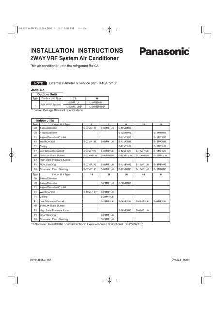
INSTALLATION INSTRUCTIONS<br />
2WAY VRF System Air Conditioner<br />
This air conditioner uses the refrigerant R410A.<br />
NOTE<br />
Model No.<br />
Type<br />
U<br />
External diameter of service port R410A: 5/16"<br />
Indoor Units<br />
Type<br />
Indoor Unit Type 7 9 12 15 18<br />
Type<br />
Outdoor Units<br />
Outdoor Unit Type 72<br />
96<br />
2WAY VRF System<br />
* Salt-Air Damage Resistant Specifications.<br />
D1<br />
U1<br />
1-<strong>Way</strong> Cassette<br />
4-<strong>Way</strong> Cassette<br />
U-72ME1U9 U-96ME1U9<br />
U-72ME1U9E* U-96ME1U9E*<br />
S-07MD1U6<br />
S-09MD1U6<br />
S-12MD1U6<br />
S-12MU1U6<br />
* 1 Necessary to install the External Electronic Expansion Valve Kit (Optional : CZ-P56SVK1U)<br />
S-18MU1U6<br />
Y1 4-<strong>Way</strong> Cassette 60 × 60 S-12MY1U6 S-18MY1U6<br />
K1 Wall Mounted S-07MK1U6 S-09MK1U6 S-12MK1U6 S-18MK1U6<br />
T1<br />
Ceiling<br />
S-12MT1U6<br />
S-18MT1U6<br />
F1 Low Silhouette Ducted S-07MF1U6 S-09MF1U6 S-12MF1U6 S-15MF1U6 S-18MF1U6<br />
M1 Slim Low Static Ducted<br />
E1 High Static Pressure Ducted<br />
P1<br />
Floor Standing<br />
R1 Concealed Floor Standing<br />
D1 1-<strong>Way</strong> Cassette<br />
S-07MM1U6 S-09MM1U6 S-12MM1U6 S-15MM1U6 S-18MM1U6<br />
S-07MP1U6<br />
S-07MR1U6<br />
S-09MP1U6<br />
S-09MR1U6<br />
S-12MP1U6<br />
S-12MR1U6<br />
S-15MP1U6<br />
S-15MR1U6<br />
S-18MP1U6<br />
S-18MR1U6<br />
Indoor Unit Type 19 24 36 48 54<br />
U1 4-<strong>Way</strong> Cassette S-24MU1U6 S-36MU1U6<br />
Y1 4-<strong>Way</strong> Cassette 60 × 60<br />
K1<br />
Wall Mounted<br />
S-19MS1U6* 1<br />
S-24MK1U6<br />
T1 Ceiling S-24MT1U6<br />
F1 Low Silhouette Ducted S-24MF1U6<br />
M1 Slim Low Static Ducted<br />
S-36MF1U6 S-48MF1U6 S-54MF1U6<br />
E1 High Static Pressure Ducted S-36ME1U6 S-48ME1U6<br />
P1 Floor Standing S-24MP1U6<br />
R1 Concealed Floor Standing<br />
S-24MR1U6<br />
85464369527012 CV6233186894
IMPORTANT!<br />
Please Read Before Starting<br />
This air conditioning system meets strict safety and operating<br />
standards. As the installer or service person, it is an<br />
important part of your job to install or service the system so<br />
it operates safely and efficiently.<br />
For safe installation and trouble-free operation, you must:<br />
Carefully read this instruction booklet before beginning.<br />
Follow each installation or repair step exactly as shown.<br />
Observe all local, state, and national electrical codes.<br />
Pay close attention to all warning and caution notices<br />
given in this manual.<br />
This symbol refers to a hazard or<br />
unsafe practice which can result<br />
WARNING<br />
in severe personal injury or death.<br />
This symbol refers to a hazard or<br />
unsafe practice which can result<br />
CAUTION in personal injury or product or<br />
property damage.<br />
If Necessary, Get Help<br />
These instructions are all you need for most installation<br />
sites and maintenance conditions. If you require help for a<br />
special problem, contact our sales/service outlet or your<br />
certified dealer for additional instructions.<br />
In Case of Improper <strong>Installation</strong><br />
The manufacturer shall in no way be responsible for<br />
improper installation or maintenance service, including failure<br />
to follow the instructions in this document.<br />
SPECIAL PRECAUTIONS<br />
WARNING When Wiring<br />
ELECTRICAL SHOCK CAN CAUSE<br />
SEVERE PERSONAL INJURY OR DEATH.<br />
ONLY A QUALIFIED, EXPERIENCED<br />
ELECTRICIAN SHOULD ATTEMPT TO<br />
WIRE THIS SYSTEM.<br />
Do not supply power to the unit until all wiring and tubing<br />
are completed or reconnected and checked.<br />
Highly dangerous electrical voltages are used in this<br />
system. Carefully refer to the wiring diagram and these<br />
instructions when wiring. Improper connections and inadequate<br />
grounding can cause accidental injury or death.<br />
Ground the unit following local electrical codes.<br />
Connect all wiring tightly. Loose wiring may cause overheating<br />
at connection points and a possible fire hazard.<br />
To prevent possible hazards from insulation failure,<br />
the unit must be grounded.<br />
When Transporting<br />
Be careful when picking up and moving the indoor and<br />
outdoor units. Get a partner to help, and bend your knees<br />
when lifting to reduce strain on your back. Sharp edges or<br />
thin aluminum fins on the air conditioner can cut your fingers.<br />
2<br />
When Installing…<br />
Select an installation location which is rigid and strong<br />
enough to support or hold the unit, and select a location<br />
for easy maintenance.<br />
…In a Room<br />
Properly insulate any tubing run inside a room to prevent<br />
“sweating” that can cause dripping and water damage to<br />
walls and floors.<br />
CAUTION<br />
When Connecting Refrigerant Tubing<br />
WARNING<br />
Keep the fire alarm and the air outlet at<br />
least 5 feet away from the unit.<br />
…In Moist or Uneven Locations<br />
Use a raised concrete pad or concrete blocks to provide a<br />
solid, level foundation for the outdoor unit. This prevents<br />
water damage and abnormal vibration.<br />
…In an Area with High Winds<br />
Securely anchor the outdoor unit down with bolts and a<br />
metal frame. Provide a suitable air baffle.<br />
…In a Snowy Area (for Heat Pump-type Systems)<br />
Install the outdoor unit on a raised platform that is higher<br />
than drifting snow. Provide snow vents.<br />
Ventilate the room well, in the event that is refrigerant<br />
gas leaks during the installation. Be careful not to allow<br />
contact of the refrigerant gas with a flame as this will<br />
cause the generation of poisonous gas.<br />
Keep all tubing runs as short as possible.<br />
Use the flare method for connecting tubing.<br />
Apply refrigerant lubricant to the matching surfaces of<br />
the flare and union tubes before connecting them, then<br />
tighten the nut with a torque wrench for a leak-free connection.<br />
Check carefully for leaks before starting the test run.<br />
When performing piping work<br />
do not mix air except for specified<br />
refrigerant (R410A) in<br />
refrigeration cycle. It causes<br />
capacity down, and risk of<br />
explosion and injury due to high<br />
tension inside the refrigerant<br />
cycle.<br />
Refrigerant gas leakage may<br />
cause fire.<br />
Do not add or replace refrigerant<br />
other than specified type.<br />
It may cause product damage,<br />
burst and injury etc.<br />
Do not leak refrigerant while piping work for an<br />
installation or re-installation, and while repairing<br />
refrigeration parts.<br />
Handle liquid refrigerant carefully as it may cause<br />
frostbite.<br />
W<br />
T<br />
C<br />
t<br />
Ch<br />
The<br />
inst<br />
era<br />
limi<br />
The<br />
er, i<br />
and<br />
laye<br />
risk<br />
foca<br />
With<br />
buil<br />
sys<br />
tive<br />
tion<br />
Mos<br />
to r<br />
con<br />
the<br />
sma<br />
ced<br />
den<br />
eme<br />
occ
a<br />
-<br />
t<br />
When Servicing<br />
Turn the power OFF at the main power box (mains)<br />
before opening the unit to check or repair electrical<br />
parts and wiring.<br />
Keep your fingers and clothing away from any moving<br />
parts.<br />
Clean up the site after you finish, remembering to check<br />
that no metal scraps or bits of wiring have been left<br />
inside the unit being serviced.<br />
WARNING<br />
Do not clean inside the indoor and<br />
outdoor units by users. Engage<br />
authorized dealer or specialist for<br />
cleaning.<br />
In case of malfunction of this<br />
appliance, do not repair by yourself.<br />
Contact to the sales dealer or service<br />
dealer for a repair.<br />
Check of Density Limit<br />
The room in which the air conditioner is to be<br />
installed requires a design that in the event of refrigerant<br />
gas leaking out, its density will not exceed a set<br />
limit.<br />
The refrigerant (R410A), which is used in the air conditioner,<br />
is safe, without the toxicity or combustibility of ammonia,<br />
and is not restricted by laws imposed to protect the ozone<br />
layer. However, since it contains more than air, it poses the<br />
risk of suffocation if its density should rise excessively. Suffocation<br />
from leakage of refrigerant is almost non-existent.<br />
With the recent increase in the number of high density<br />
buildings, however, the installation of multi air conditioner<br />
systems is on the increase because of the need for effective<br />
use of floor space, individual control, energy conservation<br />
by curtailing heat and carrying power, etc.<br />
Most importantly, the multi air conditioner system is able<br />
to replenish a large amount of refrigerant compared to<br />
conventional individual air conditioners. If a single unit of<br />
the multi air conditioner system is to be installed in a<br />
small room, select a suitable model and installation procedure<br />
so that if the refrigerant accidentally leaks out, its<br />
density does not reach the limit (and in the event of an<br />
emergency, measures can be made before injury can<br />
occur).<br />
3<br />
Others<br />
CAUTION<br />
CAUTION<br />
Do not touch the air inlet or the<br />
sharp aluminum fins of the<br />
outdoor unit. You may get injured.<br />
Ventilate any enclosed areas when<br />
installing or testing the refrigeration<br />
system. Escaped refrigerant gas, on<br />
contact with fire or heat, can produce<br />
dangerously toxic gas.<br />
Confirm after installation that no<br />
refrigerant gas is leaking. If the gas<br />
comes in contact with a burning stove,<br />
gas water heater, electric room heater<br />
or other heat source, it can cause the<br />
generation of poisonous gas.<br />
Do not touch the air inlet or the<br />
sharp aluminum fins of the<br />
outdoor unit. You may get injured.<br />
Do not sit or step on the unit,<br />
you may fall down accidentally.<br />
Do not stick any object into the<br />
FAN CASE.<br />
You may be injured and the<br />
unit may be damaged.<br />
ASHRAE and the International Mechanical Code of the<br />
ICC as well as CSA provide guidance and define safeguards<br />
related to the use of refrigerants, all of which define<br />
a Refrigerant Concentration Level (RCL) of 25 pounds<br />
per 1,000 cubic feet for R410A refrigerant.<br />
For additional guidance and precautions related to<br />
refrigerant safety, please refer to the following documents:<br />
International Mechanical Code 2009 (IMC-2009)<br />
(or more recently revised)<br />
ASHRAE 15<br />
ASHRAE 34
Precautions for <strong>Installation</strong> Using New Refrigerant<br />
1. Care regarding tubing<br />
1-1. Process tubing<br />
● Material: Use C1220 phosphorous deoxidized copper specified in JIS H3300 “Copper and Copper Alloy Seamless<br />
Pipes and Tubes.”<br />
For tubes of ø7/8" (ø22.22 mm) or larger, use C1220 T-1/2H material or H material, and do not bend the tubes.<br />
● Tubing size: Be sure to use the sizes indicated in the table below.<br />
● Use a tube cutter when cutting the tubing, and be sure to remove any flash. This also applies to distribution joints<br />
(optional).<br />
● When bending tubing, use a bending radius that is 4 times the outer diameter of the tubing or larger.<br />
Copper tube<br />
Copper tube<br />
CAUTION<br />
Use sufficient care in handling the tubing. Seal the tubing ends with caps or tape to<br />
prevent dirt, moisture, or other foreign substances from entering. These substances<br />
can result in system malfunction.<br />
Unit: in. (mm)<br />
Material O<br />
1-2. Prevent impurities including water, dust and oxide from entering the tubing. Impurities can cause R410A refrigerant<br />
deterioration and compressor defects. Due to the features of the refrigerant and refrigerating machine oil, the<br />
prevention of water and other impurities becomes more important than ever.<br />
2. Be sure to recharge the refrigerant only in liquid form.<br />
2-1. Since R410A is a non-azeotrope, recharging the refrigerant in gas form can lower performance and cause defects<br />
in the unit.<br />
2-2. Since refrigerant composition changes and performance decreases when gas leaks, collect the remaining refrigerant<br />
and recharge the required total amount of new refrigerant after fixing the leak.<br />
3. Different tools required<br />
Outer diameter 1/4 (6.35) 3/8 (9.52) 1/2 (12.7) 5/8 (15.88) 3/4 (19.05)<br />
Wall thickness 1/32 (0.8) 1/32 (0.8) 1/32 (0.8) 5/128 (1.0) over 5/128 (1.0)<br />
Material 1/ 2 H, H<br />
Outer diameter 7/8 (22.22) 1 (25.4) 1-1/8 (28.58) 1-1/4 (31.75) 1-1/2 (38.1) 1-5/8 (41.28)<br />
Wall thickness 5/128 (1.0) 5/128 (1.0) 5/128 (1.0) 3/64 (1.1) over 3/64 (1.15) over 3/64 (1.20)<br />
3-1. Tool specifications have been changed due to the characteristics of R410A.<br />
Some tools for R22- and R407C-type refrigerant systems cannot be used.<br />
New R407C tools<br />
Item tool? compatible<br />
with R410A?<br />
Remarks<br />
Manifold gauge Yes No Types of refrigerant, refrigerating machine<br />
oil, and pressure gauge are different.<br />
Charge hose Yes No To resist higher pressure, material must be changed.<br />
Vacuum pump Yes Yes Use a conventional vacuum pump if it is equipped<br />
with a check valve. If it has no check valve,<br />
purchase and attach a vacuum pump adapter.<br />
Leak detector Yes No Leak detectors for CFC and HCFC that<br />
react to chlorine do not function because<br />
R410A contains no chlorine. Leak detector<br />
for HFC134a can be used for R410A.<br />
Flaring oil Yes No For systems that use R22, apply mineral oil (Suniso oil)<br />
to the flare nuts on the tubing to prevent refrigerant<br />
leakage. For machines that use R407C or R410A, apply<br />
synthetic oil (ether oil) to the flare nuts.<br />
* Using tools for R22 and R407C and new tools for R410A together can cause defects.<br />
4<br />
Unit: in. (mm)<br />
Manifold gauge<br />
Vacuum pump<br />
Outlet<br />
Inlet
3-2. Use R410A exclusive cylinder only.<br />
New refrigerant R410A cannot be used for<br />
earlier models<br />
1. Compressor specifications are different.<br />
If recharging a R22 or R407C compressor with<br />
R410A, durability will significantly decrease since<br />
some of the materials used for compressor parts are<br />
different.<br />
2. Existing tubing cannot be used (especially R22).<br />
Completely cleaning out residual refrigerating<br />
machine oil is impossible, even by flushing.<br />
3. Refrigerating machine oil differs (R22).<br />
Since R22 refrigerating machine oil is mineral oil, it<br />
does not dissolve in R410A. Therefore, refrigerating<br />
machine oil discharged from the compressor can<br />
cause compressor damage.<br />
R22 refrigerating machine oil Mineral oil (Suniso oil)<br />
R407C refrigerating machine oil Synthetic fluid (ether oil)<br />
R410A refrigerating machine oil Synthetic fluid (ether oil)<br />
Single-outlet valve<br />
(with siphon tube)<br />
Liquid refrigerant should be recharged<br />
with the cylinder standing on end as<br />
shown.<br />
5<br />
Liquid<br />
Valve
IMPORTANT! . . . . . . . . . . . . . . . . . . . . . . . . . . . . . 2<br />
Please Read Before Starting<br />
Check of Density Limit<br />
Precautions for <strong>Installation</strong> Using New Refrigerant<br />
New refrigerant R410A cannot be used for earlier models<br />
1. GENERAL . . . . . . . . . . . . . . . . . . . . . . . . . . . . . 7<br />
1-1. Tools Required for <strong>Installation</strong> (not supplied)<br />
1-2. Accessories Supplied<br />
1-3. Type of Copper Tube and Insulation Material<br />
1-4. Additional Materials Required for <strong>Installation</strong><br />
1-5. Tubing Length<br />
1-6. Tubing Size<br />
1-7. Straight Equivalent Length of Joints<br />
1-8. Additional Refrigerant Charge<br />
1-9. System Limitations<br />
1-10. Check of Limit Density<br />
1-11. Installing Distribution Joint<br />
1-12. Optional Distribution Joint Kits<br />
1-13. Example of Tubing Size Selection and<br />
Refrigerant Charge Amount<br />
2. SELECTING THE INSTALLATION SITE . . . . . 16<br />
2-1. Outdoor Unit<br />
2-2. Removing Fin Guard for Heat Exchanger<br />
2-3. Shield for Horizontal Exhaust Discharge<br />
2-4. Installing the Outdoor Unit in Heavy Snow<br />
Areas<br />
2-5. Precautions When Installing in Heavy Snow<br />
Areas<br />
2-6. Dimensions of Wind Ducting<br />
2-7. Dimensions of Snow Ducting<br />
3. HOW TO INSTALL THE OUTDOOR UNIT . . . 20<br />
3-1. Transporting<br />
3-2. Installing the Outdoor Unit<br />
3-3. Routing the Tubing<br />
3-4. Prepare the Tubing<br />
3-5. Connect the Tubing<br />
4. ELECTRICAL WIRING . . . . . . . . . . . . . . . . . . 24<br />
4-1. General Precautions on Wiring<br />
4-2. Recommended Wire Length and Wire<br />
Diameter for Power Supply System<br />
4-3. Wiring System Diagram<br />
CONTENTS<br />
Page Page<br />
6<br />
5. HOW TO PROCESS TUBING . . . . . . . . . . . . 28<br />
5-1. Connecting the Refrigerant Tubing<br />
5-2. Connecting Tubing Between Indoor and<br />
Outdoor Units<br />
5-3. Insulating the Refrigerant Tubing<br />
5-4. Taping the Tubes<br />
5-5. Finishing the <strong>Installation</strong><br />
6. AIR PURGING . . . . . . . . . . . . . . . . . . . . . . . . . 32<br />
■ Air Purging with a Vacuum Pump (for Test Run)<br />
Preparation<br />
7. TEST RUN . . . . . . . . . . . . . . . . . . . . . . . . . . . . 35<br />
7-1. Preparing for Test Run<br />
7-2. Test Run Procedure<br />
7-3. Main Outdoor Unit PCB Setting<br />
7-4. Auto Address Setting<br />
7-5. Remote Controller Test Run Settings<br />
7-6. Caution for Pump Down<br />
7-7. Meaning of Alarm Messages
1. GENERAL<br />
This booklet briefly outlines where and how to install the air conditioning system. Please read over the entire set of instructions for<br />
the outdoor unit and make sure all accessory parts listed are with the system before beginning.<br />
1-1. Tools Required for <strong>Installation</strong> (not supplied)<br />
1. Flathead screwdriver<br />
2. Phillips head screwdriver<br />
3. Knife or wire stripper<br />
4. Tape measure<br />
5. Level gauge<br />
6. Sabre saw or key hole saw<br />
7. Hacksaw<br />
8. Core bits<br />
9. Hammer<br />
10. Drill<br />
11. Tube cutter<br />
12. Tube flaring tool<br />
13. Torque wrench<br />
14. Adjustable wrench<br />
15. Reamer (for deburring)<br />
1-2. Accessories Supplied<br />
See Table 1-1.<br />
Table 1-1 Outdoor Unit<br />
Part name<br />
Connection tubing<br />
Figure<br />
Outer<br />
Inner<br />
diameter<br />
diameter<br />
o1-1/8"(o28.58)<br />
o3/4"(o19.05)<br />
Outer<br />
Inner<br />
diameter<br />
diameter<br />
o7/8"(o22.22) o3/4"(o19.05)<br />
Instruction manual paper<br />
7<br />
1-3. Type of Copper Tube and Insulation Material<br />
If you wish to purchase these materials separately from a<br />
local source, you will need:<br />
1. Deoxidized annealed copper tube for refrigerant tubing.<br />
2. Foamed polyethylene insulation for copper tubes as<br />
required to precise length of tubing. Wall thickness of the<br />
insulation should be not less than 5/16".<br />
3. Use insulated copper wire for field wiring. Wire size varies<br />
with the total length of wiring.<br />
Refer to “4. ELECTRICAL WIRING” for details.<br />
CAUTION<br />
Check local electrical codes and<br />
regulations before obtaining<br />
wire. Also, check any specified<br />
instructions or limitations.<br />
1-4. Additional Materials Required for <strong>Installation</strong><br />
1. Refrigeration (armored) tape<br />
2. Insulated staples or clamps for connecting wire<br />
(See your local codes.)<br />
3. Putty<br />
4. Refrigeration tubing lubricant<br />
5. Clamps or saddles to secure refrigerant tubing<br />
6. Scale for weighing<br />
U-72ME1U9<br />
U-72ME1U9E<br />
(6 ton)<br />
0<br />
Q’ty<br />
U-96ME1U9<br />
U-96ME1U9E<br />
(8 ton)<br />
1 1<br />
1<br />
1<br />
1
1-6. Tubing Size<br />
Table 1-3 Main Tubing Size (LA)<br />
BTU/h<br />
(kW)<br />
Total system tonnage<br />
Combined outdoor models<br />
Gas tubing<br />
Liquid tubing<br />
72,000<br />
(21.1)<br />
6<br />
96,000<br />
(28.1)<br />
U-72ME1U9(E) U-96ME1U9(E)<br />
o3/4"<br />
(o19.05)<br />
o3/8"<br />
(o9.52)<br />
8<br />
o7/8"<br />
(o22.22)<br />
139,000<br />
(40.7)<br />
168,000<br />
(49.2)<br />
12 14<br />
192,000<br />
(56.3)<br />
16<br />
203,000<br />
(59.5)<br />
18<br />
U-72ME1U9(E)<br />
U-72ME1U9(E) U-72ME1U9(E)<br />
U-96ME1U9(E) U-96ME1U9(E)<br />
U-96ME1U9(E) U-72ME1U9(E)<br />
U-72ME1U9(E)<br />
U-72ME1U9(E)<br />
o1-1/8"<br />
(o28.58)<br />
o1/2"<br />
o5/8"<br />
(o12.7) (o15.88)<br />
9<br />
240,000<br />
(70.3)<br />
20<br />
U-96ME1U9(E)<br />
U-72ME1U9(E)<br />
U-72ME1U9(E)<br />
264,000<br />
(77.4)<br />
22<br />
U-96ME1U9(E)<br />
U-96ME1U9(E)<br />
U-72ME1U9(E)<br />
o1-3/8"<br />
(o34.92)<br />
o3/4"<br />
(o19.05)<br />
Unit: in. (mm)<br />
288,000<br />
(84.4)<br />
24<br />
U-96ME1U9(E)<br />
U-96ME1U9(E)<br />
U-96ME1U9(E)<br />
*1: If future extension is planned, select the tubing diameter based on the total tonnage after extension.<br />
However extension is not possible if the resulting tubing size is two ranks higher.<br />
*2: The balance tube (outdoor unit tube) diameter is ø1/4".<br />
*3: Type 1 tubing should be used for the refrigerant tubes.<br />
*4: If the length of the longest tube (L1) exceeds 295 ft. (equivalent length), increase the main tube (LM) size by 1 rank for the gas<br />
and liquid tubes. (Use field-supply reducers.) (Select from Table 1-3 and Table 1-9.)<br />
*5: If the longest main tube length (LM) exceeds 164 ft., increase the main tube size at the portion before 164 ft. by 1 rank for the<br />
gas tubes.<br />
(For the portion that exceeds 164 ft., set based on the main tube sizes (LA) listed in the table above.)<br />
■ Size of tubing (LO) between outdoor units<br />
Select the size of tubing between outdoor units based on the main tubing size (LA) as given in the table above.<br />
Table 1-4 Main Tubing Size After Distribution (LB, LC...)<br />
Total capacity<br />
after distribution<br />
Tubing size<br />
BTU/h<br />
(kW)<br />
Gas tubing<br />
Liquid tubing<br />
Balance tubing<br />
Below BTU/h<br />
Over BTU/h<br />
Gas tubing<br />
Liquid tubing<br />
Note: In case the total capacity of connected indoor units exceeds the total capacity of the outdoor units, select the main tubing<br />
size for the total capacity of the outdoor units. (Especially the main tubing segments of LA, LB and LF.)<br />
Table 1-5 Outdoor Unit Tubing Connection Size<br />
72,000<br />
(21.1)<br />
ø3/4" * 1<br />
(ø19.05) * 1<br />
ø3/8" (ø9.52)<br />
Brazing connection<br />
Flare connection<br />
ø1/4" (ø6.35)<br />
Flare connection<br />
*1 If the size of tubing (LA) is less than 16.4 feet, it is recommended<br />
that the tubing diameter be larger than ø7/8" (ø22.22).<br />
*2 If the size of tubing (LA) is less than 16.4 feet, it is recommended<br />
that the tubing diameter be larger than ø1-1/8" (ø28.58).<br />
24,200 54,600 76,800 102,400 143,300 178,800 238,900 334,400 –<br />
–<br />
ø1/2"<br />
(ø12.7)<br />
ø3/8"<br />
(ø9.52)<br />
24,200<br />
ø5/8"<br />
(ø15.88)<br />
ø3/8"<br />
(ø9.52)<br />
54,600<br />
ø3/4"<br />
(ø19.05)<br />
ø3/8"<br />
(ø9.52)<br />
96,000<br />
(28.1)<br />
ø7/8" * 2<br />
(ø22.22)* 2<br />
ø3/8" (ø9.52)<br />
76,800<br />
ø7/8"<br />
(ø22.22)<br />
ø3/8"<br />
(ø9.52)<br />
( A – C)<br />
Unit: in. (mm)<br />
Table 1-6 Refrigerant Charge Amount at Shipment (for outdoor unit)<br />
DC U-72ME1U9, U-72ME1U9E U-96ME1U9, U-96ME1U9E<br />
(oz) 416 416<br />
Table 1-7 Indoor Unit Tubing Connection Size<br />
102,400<br />
ø1-1/8"<br />
(ø28.58)<br />
ø1/2"<br />
(ø12.7)<br />
143,300<br />
ø1-1/8"<br />
(ø28.58)<br />
ø1/2"<br />
(ø12.7)<br />
Balance tube<br />
178,800<br />
ø1-1/8"<br />
(ø28.58)<br />
ø5/8"<br />
(ø15.88)<br />
Liquid tube<br />
238,900<br />
ø1-3/8"<br />
(ø34.92)<br />
ø3/4"<br />
(ø19.05)<br />
Indoor unit type 7 9 12 15 18 19 24 36 48 54<br />
Gas tubing<br />
Liquid tubing<br />
o1/2" (o12.7)<br />
o1/4" (o6.35)<br />
Note: Use C1220T-1/2H material for tubing over ø3/4" (ø22.22).<br />
o5/8" (o15.88)<br />
o3/8" (o9.52)<br />
Unit: in. (mm)<br />
Unit: in. (mm)<br />
334,400<br />
ø1-3/8"<br />
(ø34.92)<br />
ø3/4"<br />
(ø19.05)<br />
Gas tube
1-7. Straight Equivalent Length of Joints<br />
Design the tubing system by referring to the following table for the straight equivalent length of joints.<br />
Table 1-8 Straight Equivalent Length of Joints<br />
Gas tubing size (in. (mm))<br />
1-9. System Limitations<br />
Table 1-11 System Limitations<br />
1/2"<br />
(12.7)<br />
5/8"<br />
(15.88)<br />
Max. No. allowable connected outdoor units 3 *1<br />
Max. capacity allowable connected outdoor units 288,000 BTU/h (24 ton, 84.4 kW)<br />
Max. connectable indoor units 40<br />
Max. allowable indoor/outdoor capacity ratio 50 – 130 %<br />
*1: Up to 3 units can be connected if the system has been extended.<br />
10<br />
3/4"<br />
(19.05)<br />
7/8"<br />
(22.22)<br />
1"<br />
(25.4)<br />
1-1/8"<br />
(28.58)<br />
1-3/8"<br />
(34.92)<br />
90° elbow 1 1.1 1.4 1.6 1.7 1.9 2.5 2.8<br />
45° elbow 0.8 0.9 1 1.2 1.3 1.4 1.8 2.0<br />
U-shape tube bent (R2-3/8" – 4" (60 – 100)) 3 3.4 4.1 4.7 5.1 5.6 7.4 8.4<br />
Trap bend 7.5 9.2 10.5 12.5 14.1 15.4 19.2 22.3<br />
Y-branch distribution joint Equivalent length conversion not needed.<br />
Ball valve for service Equivalent length conversion not needed.<br />
Table 1-9 Refrigerant tubing (Existing tubing can be used.)<br />
Tubing size (in. (mm))<br />
Material O Material 1/2H • H<br />
ø1/4" (ø6.35) t1/32" (t0.8) ø7/8" (ø22.22) t5/128" (t1.0)<br />
ø3/8" (ø9.52) t1/32" (t0.8) ø1" (ø25.4) t5/128" (t1.0)<br />
ø1/2" (ø12.7) t1/32" (t0.8) ø1-1/8" (ø28.58) t5/128" (t1.0)<br />
ø5/8" (ø15.88) t5/128" (t1.0) ø1-1/4" (ø31.75) t3/64" (t1.1)<br />
ø3/4" (ø19.05) over t5/128" (t1.0) ø1-1/2" (ø38.1) over t3/64" (t1.15)<br />
ø1-5/8" (ø41.28) over t3/64" (t1.20)<br />
1-5/8"<br />
(41.28)<br />
* When bending the tubes, use a bending<br />
radius that is at least 4 times the outer<br />
diameter of the tubes.<br />
In addition, take sufficient care to avoid<br />
crushing or damaging the tubes when<br />
bending them.<br />
1-8. Additional Refrigerant Charge<br />
Additional refrigerant charge amount is calculated from the liquid tubing total length and a type of outdoor unit as follows.<br />
Table 1-10-1 Amount of Additional Refrigerant Charge Per ft., According to Liquid Tubing Size<br />
Liquid tubing size Amount of additional<br />
(in. (mm)) refrigerant charge (oz/ft.)<br />
ø1/4" (ø6.35) 0.279<br />
ø3/8" (ø9.52) 0.602<br />
ø1/2" (ø12.7) 1.38<br />
ø5/8" (ø15.88) 1.99<br />
ø3/4" (ø19.05) 2.78<br />
ø7/8" (ø22.22) 3.93<br />
Unit: ft.<br />
Required amount of additional refrigerant charge = [(Amount of additional refrigerant<br />
charge per ft. of each size of liquid tube × its tube length) + (...) + (...)] + [Necessary<br />
amount of additional refrigerant charge per outdoor unit + (...) + (...)]<br />
* Always charge accurately using a scale for weighing.<br />
* If the existing tubing is used, and the amount of on-site additional refrigerant<br />
charge exceeds the value listed below, then change the size of the tubing to<br />
reduce the amount of refrigerant.<br />
Max. additional charge for 1 outdoor unit :62 lbs<br />
Max. additional charge for 2 outdoor units :111 lbs<br />
Table 1-10-2 Necessary Amount of Additional Refrigerant Charge Per Outdoor Unit<br />
Further charge a certain amount listed below in addition to the amount of refrigerant charge.<br />
U-72ME1U9, U-72ME1U9E U-96ME1U9, U-96ME1U9E<br />
42 oz/unit 42 oz/unit
Always check the gas density<br />
WARNING limit for the room in which the<br />
unit is installed.<br />
1-10. Check of Limit Density<br />
When installing an air conditioner in a room, it is necessary to<br />
ensure that even if the refrigerant gas accidentally leaks out, its<br />
density does not exceed the limit level for that room.<br />
Pay special attention to any location,<br />
CAUTION<br />
such as a basement, etc., where leaking<br />
refrigerant can accumulate, since<br />
refrigerant gas is heavier than air.<br />
1-11. Installing Distribution Joint<br />
(1) Refer to “HOW TO ATTACH DISTRIBUTION JOINT” enclosed<br />
with the optional distribution joint kit<br />
(CZ-P680PJ1U, CZ-P1350PJ1U, CZ-P160BK1U,<br />
CZ-P680BK1U, CZ-P1350BK1U).<br />
(2) When creating a branch using a commercially available<br />
T-joint (header joint system), orient the main tubing so that it is<br />
either horizontal (level) or vertical. In order to prevent accumulation<br />
of refrigerant oil in stopped units, if the main tubing is<br />
horizontal then each branch tubing length should be at an<br />
angle that is greater than horizontal. If the main tubing is vertical,<br />
provide a raised starting portion for each branch.<br />
(3) If there are height differences between indoor units or if branch<br />
tubing that follows a distribution joint is connected to only 1<br />
unit, a trap or ball valve must be added to that<br />
distribution joint. (When adding the ball valve, locate it<br />
within 1.3 ft. of the distribution joint.)<br />
If a trap or ball valve is not added, do not operate the system<br />
before repairs to a malfunctioning unit are<br />
completed. (The refrigerant oil sent through the tubing to<br />
the malfunctioning unit will accumulate and may damage<br />
the compressor.)<br />
11<br />
Tube branching methods (horizontal use)<br />
Ball valve<br />
(BV: purchased<br />
separately)<br />
Main tubing<br />
B<br />
Main tubing<br />
15 to 30<br />
Horizontal A<br />
A line<br />
View as seen<br />
from arrow<br />
Arrow view<br />
Types of vertical trap specifications<br />
(When using ball valve)<br />
Indoor unit (1)<br />
Indoor unit (more than 2 units)<br />
(If only 1 unit is connected, a ball valve<br />
is also needed on this side.)<br />
(When not using ball valve)<br />
Horizontal<br />
Indoor unit<br />
Branch tubing is<br />
directed upward.<br />
More than<br />
8 inch<br />
Indoor unit is directed downward<br />
B<br />
(Each unit is connected<br />
to tubing that is either<br />
level or is directed<br />
downward.)
1-12. Optional Distribution Joint Kits<br />
See the installation instructions packaged with the distribution joint kit for the installation procedure.<br />
Table 1-12<br />
Model name Cooling capacity after distribution Remarks<br />
1. CZ-P680PJ1U 232,000 BTU/h (68.0 kW) or less For outdoor unit<br />
2. CZ-P1350PJ1U 460,700 BTU/h (135.0 kW) or less For outdoor unit<br />
3. CZ-P160BK1U 76,400 BTU/h (22.4 kW) or less For indoor unit<br />
4. CZ-P680BK1U 232,000 BTU/h (68.0 kW) or less For indoor unit<br />
5. CZ-P1350BK1U 460,700 BTU/h (135.0 kW) or less For indoor unit<br />
■ Tubing size (with thermal insulation)<br />
1. CZ-P680PJ1U<br />
For outdoor unit (Capacity after distribution joint is 232,000 BTU/h (68.0 kW) or less.)<br />
Example:<br />
Gas tubing Liquid tubing<br />
Distr ib ution<br />
Joint<br />
Reducing<br />
Joints<br />
6-59/64<br />
5-5/16<br />
C D E F<br />
C<br />
C<br />
Insulation<br />
4 - 3 1 / 6 4<br />
12<br />
Insulation<br />
G<br />
Distr ib ution<br />
Joint<br />
4-21/64<br />
3-13/16<br />
Table 1-13 Size of connection point on each part (Shown are inside diameters of tubing)<br />
Table 1-14 Size of connection point on each part (Shown are inside diameters of tubing)<br />
G<br />
G<br />
H<br />
I<br />
HI<br />
Reducing<br />
Joints<br />
Size Part A Part B Part C Part D Part E Part F Part G Part H Part I<br />
in. (mm)<br />
¯1- 3/8" ø1-1/4" ø1-1/8" ø1" ø7/8" ø3/4" ø5/8" ø1/2" ø3/8"<br />
(ø34.92) (ø31.75) (ø28.58) (ø25.4) (ø22.22) (ø19.05) (ø15.88) (ø12.7) (ø9.52)<br />
2 - 5 3 / 6 4<br />
Unit: in.<br />
2. CZ-P1350PJ1U<br />
For outdoor unit (Capacity after distribution joint is greater than 232,000 BTU/h (68.0 kW) and no more than<br />
460,700 BTU/h (135.0 kW).)<br />
Example:<br />
Size Part A Part B Part C Part D Part E Part F Part G Part H Part I<br />
in. (mm)<br />
D<br />
C<br />
(A)<br />
Insulation<br />
B<br />
6-57/64<br />
5-5/16<br />
Distr ib ution<br />
Joint<br />
Gas tubing Liquid tubing<br />
(A)<br />
B<br />
C<br />
D<br />
B<br />
E<br />
F<br />
C<br />
(A)<br />
D<br />
Reducing<br />
Joints<br />
4 - 3 1 / 6 4<br />
ø1-3/8" ø1-1/4" ø1-1/8" ø1" ø7/8" ø3/4" ø5/8" ø1/2" ø3/8"<br />
(ø34.92) (ø31.75) (ø28.58) (ø25.4) (ø22.22) (ø19.05) (ø15.88) (ø12.7) (ø9.52)<br />
F<br />
Insulation<br />
( ): Outside dimension<br />
G<br />
Distr ib ution<br />
Joint<br />
4-21/64<br />
3-13/16<br />
G<br />
G<br />
H<br />
I<br />
HI<br />
Reducing<br />
Joints<br />
2 - 5 3 / 6 4<br />
Unit: in.
3. CZ-P160BK1U<br />
Use: For indoor unit (Capacity after distribution joint is 76,400 BTU/h (22.4 kW) or less.)<br />
Example:<br />
A<br />
Insulation<br />
4-21/64<br />
3-13/16<br />
Gas tubing Liquid tubing<br />
B<br />
Distr ib utio n<br />
Joint B<br />
B<br />
C<br />
A<br />
D<br />
Insulation<br />
C<br />
6-57/64<br />
5-5/16<br />
2 - 5 3 / 6 4<br />
13<br />
4-21/64<br />
3-13/16<br />
C<br />
Distr ib utio n<br />
Joint<br />
C<br />
Table 1-15 Size of connection point on each part (Shown are inside diameters of tubing)<br />
Size Part A Part B Part C Part D Part E<br />
in. (mm)<br />
Example:<br />
D C B<br />
Distr ib ution<br />
Joint<br />
Insulation<br />
A<br />
Gas tubing Liquid tubing<br />
A<br />
B<br />
C<br />
D<br />
E<br />
F<br />
6-57/64<br />
5-5/16<br />
A<br />
B C D<br />
Reducing<br />
Joints<br />
E F<br />
4 - 3 1 / 6 4<br />
G F<br />
Distr ib ution<br />
Joint<br />
Insulation<br />
E<br />
4-21/64<br />
3-13/16<br />
Size Part A Part B Part C Part D Part E Part F Part G Part H<br />
in. (mm)<br />
Example:<br />
D<br />
(A)<br />
C<br />
Insulation<br />
ø3/4" ø5/8" ø1/2" ø3/8" ø1/4"<br />
(ø19.05) (ø15.88) (ø12.7) (ø9.52) (ø6.35)<br />
B<br />
Distr ib ution<br />
Joint<br />
Gas tubing Liquid tubing<br />
C<br />
D<br />
E<br />
F<br />
G<br />
H<br />
B<br />
B<br />
(A)<br />
C D<br />
(A)<br />
Reducing<br />
Joints<br />
4 - 3 1 / 6 4<br />
( ): Outside dimension<br />
F<br />
Distr ib ution<br />
Joint<br />
Insulation<br />
G<br />
E<br />
F<br />
G<br />
H<br />
4-21/64<br />
3-13/16<br />
G<br />
H<br />
I<br />
J<br />
C DE<br />
ø1-1/8" ø1" ø7/8" ø3/4" ø5/8" ø1/2" ø3/8" ø1/4"<br />
(ø28.58) (ø25.4) (ø22.22) (ø19.05) (ø15.88) (ø12.7) (ø9.52) (ø6.35)<br />
D<br />
E<br />
E<br />
G<br />
F G H<br />
Reducing<br />
Joints<br />
F<br />
H<br />
Unit: in.<br />
4. CZ-P680BK1U<br />
Use: For indoor unit (Capacity after distribution joint is greater than 76,400 BTU/h (22.4 kW) and no more than 232,000 BTU/h (68.0 kW).)<br />
Table 1-16 Size of connection point on each part (Shown are inside diameters of tubing)<br />
Unit: in.<br />
5. CZ-P1350BK1U<br />
Use: For indoor unit (Capacity after distribution joint is greater than 232,000 BTU/h (68.0 kW) and no more than 460,700 BTU/h (135.0 kW).)<br />
Table 1-17 Size of connection point on each part (Shown are inside diameters of tubing)<br />
Reducing<br />
Joints<br />
2 - 5 3 / 6 4<br />
2 - 5 3 / 6 4<br />
2 - 5 3 / 6 4<br />
Unit: in.<br />
Size Part A Part B Part C Part D Part E Part F Part G Part H Part I Part J<br />
in. (mm)<br />
ø1-3/8"<br />
(ø34.92)<br />
ø1-1/4"<br />
(ø31.75)<br />
ø1-1/8"<br />
(ø28.58)<br />
ø1"<br />
(ø25.4)<br />
ø7/8"<br />
(ø22.22)<br />
ø3/4"<br />
(ø19.05)<br />
ø5/8"<br />
(ø15.88)<br />
ø1/2"<br />
(ø12.7)<br />
ø3/8"<br />
(ø9.52)<br />
ø1/4"<br />
(ø6.35)
1-13. Example of Tubing Size Selection and Refrigerant Charge Amount<br />
Additional refrigerant charging<br />
Based on the values in Tables 1-3, 4, 5, 7, 10-1 and 10-2, use the liquid tubing size and length, and calculate the amount of additional<br />
refrigerant charge using the formula below.<br />
Required additional<br />
refrigerant charge (oz)<br />
Example:<br />
CAUTION<br />
Outdoor unit<br />
96 type 96 type<br />
B<br />
A<br />
LA<br />
● Example of each tubing length<br />
= Necessary Amount of Additional Refrigerant Charge Per Outdoor Unit<br />
+ 3.93 × (a) + 2.78 × (b) + 1.99 × (c) + 1.38 × (d) + 0.602 × (e) + 0.279 × (f)<br />
(a) : Liquid tubing Total length of ø7/8" (ft.) (d) : Liquid tubing Total length of ø1/2" (ft.)<br />
(b) : Liquid tubing Total length of ø3/4" (ft.) (e) : Liquid tubing Total length of ø3/8" (ft.)<br />
(c) : Liquid tubing Total length of ø5/8" (ft.) ( f ) : Liquid tubing Total length of ø1/4" (ft.)<br />
● Charging procedure<br />
Be sure to charge with R410A refrigerant in liquid form.<br />
1. After performing a vacuum, charge with refrigerant from the liquid tubing side. At this time, all valves must be in the “fully<br />
closed” position.<br />
2. If it was not possible to charge the designated amount, operate the system in Cooling mode while charging with refrigerant<br />
from the gas tubing side. (This is performed at the time of the test run. For this, all valves must be in the “fully open” position.<br />
However if only one outdoor unit is installed, a balance tube is not used. Therefore, leave the valves fully closed.)<br />
Charge with R410A refrigerant in liquid form.<br />
With R410A refrigerant, charge while adjusting the amount being fed a little at a time in order to prevent liquid refrigerant from<br />
backing up.<br />
● After charging is completed, turn all valves to the “fully open” position.<br />
● Replace the tubing covers as they were before.<br />
1. R410A additional charging absolutely must<br />
be done through liquid charging.<br />
2. The R410A refrigerant cylinder has a gray<br />
base color, and the top part is pink.<br />
3. The R410A refrigerant cylinder includes a<br />
siphon tube. Check that the siphon tube is<br />
present. (This is indicated on the label at the<br />
top of the cylinder.)<br />
4. Due to differences in the refrigerant, pressure,<br />
and refrigerant oil involved in installation,<br />
it is not possible in some cases to use<br />
the same tools for R22 and for R410A.<br />
LB LC<br />
1 2 3 4<br />
48 type 48 type 48 type 36 type<br />
Main tubing Distribution joint tubing<br />
LA = 131 ft. Outdoor side Indoor side<br />
LB = 16 ft. A = 7 ft. 1 = 98 ft.<br />
LC = 16 ft. B = 7 ft.<br />
14<br />
2 = 16 ft.<br />
3 = 16 ft.<br />
4 = 65 ft.<br />
Balance tube<br />
Use a flathead screwdriver and<br />
open by turning the part with the<br />
screw groove to the right,<br />
from “–” to “|”.<br />
Liquid tube<br />
Use a hex wrench (width 5/32 inch)<br />
and turn to the left to open.<br />
Gas tube<br />
Use a flathead screwdriver and<br />
open by turning the part with the<br />
screw groove to the right,<br />
from “–” to “|”.
● Obtain liquid tubing size from Tables 1-3, 4, 5, 7 and 10-1.<br />
Main tubing<br />
LA = ø5/8 (ft.) (Total capacity of indoor unit is 179,400 BTU/h) The longest tubing length in this example<br />
LB = ø1/2 (ft.) (Total capacity of indoor unit is 131,600 BTU/h)<br />
LC = ø3/8 (ft.) (Total capacity of indoor unit is 83,800 BTU/h)<br />
(LA = 131 ft.)<br />
Distribution joint tubing<br />
Outdoor side A: ø3/8 (ft.) B: ø3/8 (ft.) (from outdoor unit connection tubing)<br />
Indoor side 1: ø3/8 (ft.) 2: ø3/8 (ft.) 3: ø3/8 (ft.) 4: ø3/8 (ft.) (from indoor unit connection tubing)<br />
● Obtain additional charge amount for each tubing size.<br />
Note 1: The charge amounts per 1 ft. are different for each liquid tubing size.<br />
ø5/8 (ft.) → LA : 131 ft. × 1.99 oz/ft. = 261 oz<br />
ø1/2 (ft.) → LB : 16 ft. × 1.38 oz/ft. = 22 oz<br />
ø3/8 (ft.) → LC + A – B + 1 – 4 : 225 ft. × 0.602 oz/ft. = 135 oz<br />
Total 418 oz<br />
Additional refrigerant charge amount is 418 oz.<br />
Note 2: Necessary amount of additional refrigerant charge per outdoor unit (U-96ME1U9) is 42 oz. (See the Table 1-10-2.)<br />
Note 1) Amount of additional charge per tubing length : 418 oz<br />
Note 2) Amount of additional charge for outdoor unit : 84 oz (42+42)<br />
Total of additional refrigerant charge amount : 502 oz<br />
Therefore, the total of additional refrigerant charge amount reaches 502 oz.<br />
● Obtain overall refrigerant charge amount.<br />
Overall refrigerant charge amount of the system indicates the calculated value shown above the additional charge amount<br />
in addition to the total of the refrigerant charge amount (shown in the Table 1-6) at the shipment of each outdoor unit.<br />
Refrigerant charge amount at shipment:<br />
U-96ME1U9 : 416 oz<br />
U-96ME1U9 : 416 oz<br />
Additional charge amount : 502 oz<br />
Grand total : 1334 oz<br />
Therefore, overall refrigerant charge amount of the system reaches 1334 oz.<br />
Remark:<br />
Be sure to include the values in Table 1-10-2 Necessary Amount of Additional Refrigerant Charge Per Outdoor Unit.<br />
CAUTION<br />
Be sure to check the limit density for the<br />
room in which the indoor unit is installed.<br />
15
2. SELECTING THE INSTALLATION SITE<br />
2-1. Outdoor Unit<br />
AVOID:<br />
● heat sources, exhaust fans, etc.<br />
● damp, humid or uneven locations<br />
● indoors (no-ventilation location)<br />
DO:<br />
● choose a place as cool as possible.<br />
● choose a place that is well ventilated.<br />
● allow enough room around the unit for air intake/<br />
exhaust and possible maintenance.<br />
● use lug bolts or equal to bolt down unit, reducing vibration<br />
and noise.<br />
<strong>Installation</strong> Space<br />
Install the outdoor unit where there is enough space for ventilation.<br />
Otherwise the unit may not operate properly. Fig. 2-2<br />
shows the minimum space requirement around the outdoor<br />
units when 3 sides are open and only 1 side is shuttered,<br />
with open space above the unit. The mounting base should<br />
be concrete or a similar material that allows for adequate<br />
drainage. Make provisions for anchor bolts, platform height,<br />
and other site-specific installation requirements.<br />
NOTE<br />
CAUTION<br />
● Leave space open above the<br />
unit.<br />
● Construct louvers or other<br />
openings in the wall, if necessary,<br />
to ensure adequate<br />
ventilation.<br />
● Do not do any wiring or tubing within 1 ft. of the front<br />
panel, because this space is needed as a servicing<br />
space for the compressor.<br />
● Ensure a base height of 4" or more to ensure that<br />
drainage water does not accumulate and freeze<br />
around the bottom of the unit.<br />
● If installing a drain pan, install the drain pan prior to<br />
installing the outdoor unit.<br />
* Make sure there is at least 6" between the outdoor<br />
unit and the ground.<br />
Also, the direction of the tubing and electrical wiring<br />
should be from the front of the outdoor unit.<br />
35<br />
(Ceiling panel dimensions)<br />
16<br />
Hot air<br />
Fig. 2-3<br />
Outdoor<br />
unit<br />
Fig. 2-1<br />
Fig. 2-2<br />
Exhaust fan<br />
Heat<br />
source<br />
Example of installation of 2 units<br />
(When wall height is below 6 ft.)<br />
* More than 4 in.<br />
More than<br />
2 in. More than<br />
1.7 ft.<br />
* More than 4 in.<br />
* More than 4 in.<br />
* However, be sure to ensure a space of 1 ft. or more at<br />
either the right side or the rear of the unit.<br />
113 (Ceiling panel dimensions)<br />
4 35<br />
(Ceiling panel dimensions)<br />
4<br />
35<br />
(Ceiling panel dimensions)<br />
31-1/8 7-7/8 31-1/8 7-7/8 31-1/8<br />
(<strong>Installation</strong> hole pitch) (<strong>Installation</strong> hole pitch) (<strong>Installation</strong> hole pitch)<br />
109-1/16 (<strong>Installation</strong> hole pitch)<br />
35(Ceiling panel dimensions)<br />
36-1/4 (<strong>Installation</strong> hole pitch)<br />
Top view Unit: in.<br />
37-1/2 (Maximum dimensions)
2-2. Removing Fin Guard for Heat Exchanger<br />
After installation of the outdoor unit, detach the fin guard for<br />
heat exchangers as following steps.<br />
1. Cut out the fin guard entirely attached to the panel and<br />
remove it from the outdoor unit. Pay careful attention not<br />
to damage the fin when cutting out the fin guard.<br />
2. If there is a case where easy to touch the sharp aluminum<br />
fin of the outdoor unit, be sure to attach a snow-proof<br />
ducting to the unit. It is recommended that the outdoor unit<br />
be located away from the touched with hands.<br />
2-3. Shield for Horizontal Exhaust Discharge<br />
It is necessary to install an air-discharge chamber (field<br />
supply) to direct exhaust from the fan horizontally if it is difficult<br />
to provide a minimum space of 7 ft. between the air-discharge<br />
outlet and a nearby obstacle. (Fig. 2-4)<br />
CAUTION<br />
In regions with heavy snowfall,<br />
the outdoor unit should be<br />
provided with a solid, raised platform<br />
and snow-proof ducting<br />
(field supply). (Fig. 2-5)<br />
2-4. Installing the Outdoor Unit in Heavy Snow<br />
Areas<br />
In locations where wind-blown snow can be a problem,<br />
snow-proof ducting (field supply) should be fitted to the unit<br />
and direct exposure to the wind should be avoided as much<br />
as possible. (Fig. 2-6) The following problems may occur if<br />
proper countermeasures are not taken:<br />
● The fan in the outdoor unit may stop running, causing the<br />
unit to be damaged.<br />
● There may be no air flow.<br />
● The tubing may freeze and burst.<br />
● The condenser pressure may drop because of strong<br />
wind, and the indoor unit may freeze.<br />
2-5. Precautions When Installing in Heavy Snow<br />
Areas<br />
a) The platform should be higher than the maximum snow<br />
depth. (Fig. 2-5)<br />
b) The 2 anchoring feet of the outdoor unit should be used<br />
for the platform, and the platform should be installed<br />
beneath the air-intake side of the outdoor unit.<br />
c) The platform foundation must be solid and the unit must<br />
be secured with anchor bolts.<br />
d) When installing on a roof subject to strong wind, countermeasures<br />
must be taken to prevent the unit from<br />
being overturned.<br />
17<br />
AVOID<br />
Fig. 2-4<br />
Without snow-<br />
proof ducting<br />
(Without platform)<br />
Fig. 2-5<br />
Fig. 2-6<br />
DO<br />
With snow-<br />
proof ducting<br />
(High platform)<br />
Fallen snow
2-6. Dimensions of Wind Ducting<br />
Reference diagram for air-discharge chamber (field supply)<br />
33-3/16<br />
35<br />
(Ceiling panel dimensions)<br />
35-1/4<br />
(Maximum bracket dimensions)<br />
Ceiling panel<br />
106-1/8<br />
(32-1/8)<br />
74-1/16<br />
35<br />
(Ceiling panel dimensions)<br />
2 1<br />
35<br />
(Ceiling panel dimensions)<br />
1 2<br />
106-1/8<br />
(32-1/8)<br />
74-1/16<br />
33-1/4<br />
35<br />
(Ceiling panel dimensions)<br />
35-1/4<br />
(Maximum bracket dimensions)<br />
Front view Right side view Front view<br />
Right side view<br />
Note: Can be installed so that the air direction is to the front, right, left or rear direction.<br />
3-unit installation<br />
113 (3-unit installation: maximum dimensions)<br />
74-1/4<br />
(2-unit installation: maximum dimensions)<br />
5-3/4<br />
5-3/4<br />
33-3/16 33-3/16 33-3/16<br />
Top view<br />
31-1/8<br />
31-1/8<br />
31-1/8<br />
(<strong>Installation</strong> hole pitch) (<strong>Installation</strong> hole pitch) (<strong>Installation</strong> hole pitch)<br />
7-7/8 7-7/8<br />
36-1/4<br />
(<strong>Installation</strong> hole pitch)<br />
(32-1/8)<br />
74-1/16<br />
106-1/8<br />
35<br />
(Ceiling panel dimensions)<br />
2 1<br />
Front view Right side view<br />
18<br />
Ceiling panel<br />
unit: in.<br />
Air direction: Front direction Air direction: Right direction<br />
unit: in.
2-7. Dimensions of Snow Ducting<br />
Reference diagram for snow-proof ducting (field supply)<br />
54<br />
31-1/2<br />
Snowfall protection duct<br />
(Field supply)<br />
Air-discharge chamber<br />
(Field supply)<br />
Snowfall protection<br />
duct (Field supply)<br />
106-1/8<br />
Air direction:<br />
Front direction<br />
(32-1/8)<br />
74-1/16<br />
Front view Right side view<br />
Board<br />
(Field supply)<br />
106-1/8<br />
74<br />
Air direction:<br />
Right direction<br />
Ceiling panel Ceiling panel<br />
31-1/2<br />
31-1/2<br />
(Air intake duct)<br />
33-3/16<br />
54<br />
9-1/2<br />
(Air outlet duct)<br />
35 9-1/2 9-1/2<br />
35<br />
9-1/2 9-1/2 35<br />
9-1/2<br />
(Ceiling panel dimensions)<br />
(Ceiling panel dimensions)<br />
(Ceiling panel dimensions)<br />
(54)<br />
32-7/8<br />
32-7/8<br />
53-5/8<br />
44-3/8<br />
Note: Can be installed so that the air direction is to the front, right, left or rear direction.<br />
3-unit installation<br />
53-5/8<br />
31-1/2<br />
44-3/8<br />
1 pc.<br />
4 pc.<br />
31-1/2<br />
35<br />
113<br />
35 35<br />
4 4<br />
3<br />
31-1/8 31-1/8 31-1/8<br />
7-7/8 7-7/8<br />
Board (Field supply)<br />
131-3/4<br />
Front view<br />
1 1<br />
44-3/8<br />
53-5/8<br />
35<br />
36-1/4<br />
37-3/8<br />
Top view (Before installation of snowfall protection duct)<br />
Snowfall protection duct<br />
(Field supply)<br />
31-1/2<br />
Ceiling panel<br />
Air-discharge chamber (Field supply)<br />
Snowfall protection<br />
duct (Field supply)<br />
44-3/8<br />
19<br />
53-5/8<br />
31-1/2<br />
31-1/2<br />
(Air intake duct)<br />
33-3/16<br />
(Air outlet duct)<br />
9-1/2 35<br />
9-1/2<br />
(Ceiling panel dimensions)<br />
(54)<br />
Front view Right side view<br />
35 (Ceiling panel dimensions)<br />
9-1/2 9-1/2<br />
2-1/8 7/8<br />
Right side view<br />
44-3/8<br />
Air-discharge chamber<br />
(Field supply)<br />
Snowfall protection duct<br />
(Field supply)<br />
53-5/8<br />
unit: in.<br />
unit: in.
3. HOW TO INSTALL THE OUTDOOR UNIT<br />
3-1. Transporting<br />
When transporting the unit, have it delivered as close to the installation site as<br />
possible without unpacking. Use a hook for suspending the unit. (Fig. 3-1)<br />
CAUTION<br />
● When hoisting the outdoor unit, pass ropes or straps under the bottom plate<br />
as shown in the figure at right. When hoisting, the angle between the rope<br />
and top panel must be 70° or greater so that the rope does not come into<br />
contact with the fan guard.<br />
(Use 2 lengths of rope 25 ft. long or longer.)<br />
● When passing the ropes through the square holes of the bottom plate:<br />
Place the rope in the outer edge of the square holes.<br />
● Use protective panels or padding at all locations where the rope contacts the<br />
outer casing or other parts to prevent scratching. In particular, use protective<br />
material (such as cloth or cardboard) to prevent the edges of the top panel<br />
from being scratched.<br />
● Be careful of the fan.<br />
There is danger of injury if the fan starts to turn during inspection. Be sure to<br />
turn OFF the remote power switch before beginning inspection.<br />
3-2. Installing the Outdoor Unit<br />
(1) Use anchor bolts (M12 or 15/32") or similar to securely anchor the unit in<br />
place. (Fig. 3-2)<br />
(2) Be sure the rubber vibration insulator and platform extend to the inside of the<br />
legs. In addition, the washers used to anchor the unit from the top must be<br />
larger than the installation anchor holes. (Figs. 3-2 and 3-3)<br />
(Positions where anchor bolts are fastened)<br />
<strong>Installation</strong> anchor hole (4-19/32 25/32 oval holes)<br />
31-1/8<br />
(<strong>Installation</strong> hole pitch)<br />
35<br />
(Ceiling panel dimensions)<br />
35<br />
(Ceiling panel dimensions)<br />
3<br />
31-1/8<br />
(<strong>Installation</strong> hole pitch)<br />
35<br />
(Ceiling panel dimensions)<br />
36-1/4<br />
(<strong>Installation</strong> hole pitch)<br />
37-1/2<br />
(Maximum dimensions)<br />
113 (Ceiling panel dimensions)<br />
35<br />
(Ceiling panel dimensions)<br />
31-1/8<br />
(<strong>Installation</strong> hole pitch)<br />
109 (<strong>Installation</strong> hole pitch)<br />
Top view<br />
Fig. 3-4<br />
35<br />
(Ceiling panel dimensions)<br />
31-1/8<br />
(<strong>Installation</strong> hole pitch)<br />
20<br />
unit: in.<br />
35<br />
(Ceiling panel dimensions)<br />
36-1/4<br />
(<strong>Installation</strong> hole pitch)<br />
37-1/2<br />
(Maximum dimensions)<br />
Plate leg<br />
Anchor bolts<br />
Washer<br />
3/4<br />
Surface where<br />
installation anchor<br />
brackets are<br />
installed<br />
2<br />
4<br />
4 – 5/8 6/8 hole<br />
Fig. 3-1<br />
4<br />
Fig. 3-2<br />
Fig. 3-3<br />
2<br />
Vibration insulator<br />
Base<br />
(Detailed view of legs)<br />
5/8<br />
1-1/2<br />
Unit: in.<br />
The vibration insulator, base, or platform must<br />
be large enough to bear the full surface of the<br />
base plate legs.<br />
Unit: in.
3-3. Routing the Tubing<br />
● The tubing can be routed out either from the front or from the bottom. (Fig. 3-6)<br />
● The connecting valve is contained inside the unit. Therefore, remove the front panel. (Fig. 3-6)<br />
(1) If the tubing is routed out from the front, use cutting pliers or a similar tool to cut out the tubing outlet slit (part indicated<br />
by ) from the tubing cover. (Figs. 3-5 and 3-6)<br />
Front<br />
Tubing cover<br />
Remove 2 screws<br />
Bottom<br />
(2) If the tubing is routed out from the bottom, remove the<br />
slit part ( ).<br />
● Use a drill bit approximately 13/64" dia. to create holes at<br />
the 4 slit hole indentations (openings).<br />
● Punch out the slit part ( ).<br />
● Be careful not to damage the base plate.<br />
Remove 11 panel<br />
screws from front<br />
panel<br />
Use cutting pliers or similar<br />
tool to cut cover out<br />
Fig. 3-5<br />
21<br />
Indentation<br />
(4 locations)<br />
Fig. 3-6<br />
Slit hole
3-4. Prepare the Tubing<br />
● Material: Use C1220 phosphorous deoxidized copper as described in JIS H3300, “Copper and Copper Alloy Seamless Pipes<br />
and Tubes.” (For tubes that are ø7/8" (ø22.22 mm) or larger, use 1/2H material or H material. For all others use O material.)<br />
● Tubing size<br />
Use the tubing size indicated in the table below.<br />
● When cutting the tubing, use a tube cutter, and be sure to remove any burrs.<br />
(The same applies to distribution tubing (optional).)<br />
● When bending the tubes, bend each tube using a radius that is at least 4 times the outer diameter of the tube.<br />
When bending, use sufficient care to avoid crushing or damaging the tube.<br />
● For flaring, use a flare tool, and be sure that flaring is performed correctly.<br />
CAUTION<br />
Use sufficient caution during preparation of the tubing. Seal the tube ends by means of caps<br />
or taping to prevent dust, moisture, or other foreign substances from entering the tubes.<br />
Refrigerant tubing (Existing tubing can be used.)<br />
3-5. Connect the Tubing<br />
● Use the supplied connector tubing. (See figure below.)<br />
72 type (6 Ton)<br />
3<br />
96 type (8 Ton)<br />
3<br />
2<br />
2<br />
1<br />
1<br />
1<br />
2<br />
3<br />
1<br />
2<br />
3<br />
Refrigerant tubing Connection method Supplied parts used?<br />
Gas tubing<br />
Liquid tubing<br />
Balance tube<br />
Refrigerant tubing Connection method Supplied parts used?<br />
Gas tubing<br />
Liquid tubing<br />
Balance tube<br />
Tubing size (in. (mm))<br />
Material O Material 1/2H • H<br />
ø1/4" (ø6.35) t1/32" (t0.8) ø7/8" (ø22.22) t5/128" (t1.0)<br />
ø3/8" (ø9.52) t1/32" (t0.8) ø1" (ø25.4) t5/128" (t1.0)<br />
ø1/2" (ø12.7) t1/32" (t0.8) ø1-1/8" (ø28.58) t5/128" (t1.0)<br />
ø5/8" (ø15.88) t5/128" (t1.0) ø1-1/4" (ø31.75) t3/64" (t1.1)<br />
ø3/4" (ø19.05) over t5/128" (t1.0) ø1-3/8" (ø34.92) over t3/64" (t1.1)<br />
Brazing<br />
Flare connection<br />
Flare connection<br />
Brazing<br />
Flare connection<br />
Flare connection<br />
No<br />
No<br />
No<br />
Yes (ø3/4" ø7/8")<br />
No<br />
No<br />
22
Refrigerant tube port<br />
● Use caulking, putty, or a similar material to fill any gaps at the<br />
refrigerant tube port ( ) in order to prevent rainwater, dust or<br />
foreign substances from entering the unit.<br />
* Perform this work even if the tubing is routed out in a downward<br />
direction.<br />
● Tighten each cap as specified below.<br />
Tightening torque for each cap<br />
Cap tightening torque<br />
Service port cap<br />
(width 19/32", 43/64")<br />
Valve cap<br />
(width 55/64", 15/16")<br />
● Precautions for brazing<br />
Be sure to replace the air inside the tube with nitrogen to prevent oxide film from forming during the brazing process.<br />
Be sure to use a damp cloth or other means to cool the valve unit during brazing.<br />
Work method<br />
Service port cap<br />
(width 19/32)<br />
Valve cap<br />
(width 55/64)<br />
Valve cap<br />
(width 55/64)<br />
Service port cap<br />
(width 19/32)<br />
Flare nut<br />
(ø1/4)<br />
Flare nut<br />
(ø3/8)<br />
CAUTION<br />
60 – 100 lbs·in (70 – 120 kgf · cm)<br />
170 – 220 lbs·in (200 – 250 kgf · cm)<br />
Do not apply an adjustable wrench<br />
to the hexagonal part.<br />
Field-supply tube<br />
Brazing locations<br />
Taping<br />
Valve cap<br />
(width 55/64)<br />
Service port cap<br />
(width 19/32)<br />
Do not use two adjustable wrenches when<br />
removing or installing the balance tube<br />
flare nut. In particular, do not apply an<br />
adjustable wrench to the hexagonal part at<br />
the top of the valve.<br />
(If force is applied to this part,<br />
gas leakage will occur.)<br />
Unit: in.<br />
Remote valve<br />
1. Be sure to use nitrogen. (Oxygen, CO2, and CFC must not be used.)<br />
2. Use a pressure-reducing valve on the nitrogen tank.<br />
3. Do not use agents intended to prevent the formation of oxide film. They will adversely affect the refrigeration<br />
oil, and may cause equipment failure.<br />
4. The balance tube is not used if only 1 outdoor unit is installed.<br />
Use the unit in the same conditions as when it was shipped from the factory.<br />
23<br />
Tubing routed out<br />
through the front side<br />
Nitrogen<br />
Tubing<br />
cover<br />
Pressure-reducing valve (regulator)<br />
Bottom<br />
plate<br />
Tubing routed out<br />
through the bottom<br />
* Be careful of the cap sizes. The sizes of the service port cap and valve cap<br />
on the 09663 type liquid tube valves are different from other valve caps.<br />
Use two adjustable wrenches, as shown in the figure,<br />
when removing the liquid tube valve flare nut.<br />
1. Do not apply a wrench to the valve cap when removing or<br />
installing the flare nuts. Doing so may damage the valve.<br />
2. If the valve cap is left off for a long period of time, refrigerant<br />
leakage will occur. Therefore, do not leave the valve cap off.<br />
3. Applying refrigerant oil to the flare surface can be effective in<br />
preventing gas leakage, however be sure to use a refrigerant<br />
oil which is suitable for the refrigerant that is used in the system.<br />
(This unit utilizes R410A refrigerant, and the refrigerant oil is<br />
ether oil (synthetic oil). However, hub oil (synthetic oil) can also<br />
be used.)
4. ELECTRICAL WIRING<br />
4-1. General Precautions on Wiring<br />
(1) Before wiring, confirm the rated voltage of the unit as<br />
shown on its nameplate, then carry out the wiring<br />
closely following the wiring diagram.<br />
(2) Provide a power outlet to be used exclusively for each<br />
unit, and a power supply disconnect, circuit breaker and<br />
earth leakage breaker for overcurrent protection should<br />
be provided in the exclusive line.<br />
(3) To prevent possible hazards from insulation failure, the<br />
unit must be grounded.<br />
(4) Each wiring connection must be done in accordance<br />
with the wiring system diagram. Wrong wiring may<br />
cause the unit to misoperate or become damaged.<br />
(5) Do not allow wiring to touch the refrigerant tubing,<br />
compressor, or any moving parts of the fan.<br />
(6) Unauthorized changes in the internal wiring can be very<br />
dangerous. The manufacturer will accept no<br />
responsibility for any damage or misoperation that<br />
occurs as a result of such unauthorized changes.<br />
4-2. Recommended Wire Length and Wire Diameter for Power Supply System<br />
Outdoor unit<br />
U-72ME1U9<br />
U-72ME1U9E<br />
U-96ME1U9<br />
U-96ME1U9E<br />
Indoor unit<br />
K1<br />
D1, U1, Y1, F1, M1, T1, P1, R1<br />
E1<br />
Control wiring<br />
(A) Inter-unit (between outdoor and<br />
indoor units) control wiring*<br />
NOTE<br />
Type<br />
Type<br />
Time delay fuse or<br />
circuit capacity<br />
40 A<br />
45 A<br />
Time delay fuse or<br />
circuit capacity<br />
(B) Remote control wiring (C) Control wiring for group control<br />
AWG #18 (0.75 mm 2 ) AWG #18 (0.75 mm 2 ) AWG #18 (0.75 mm 2 )<br />
Max. 3,280 ft. Max. 1,640 ft. Max. 650 ft. (Total)<br />
* With ring-type wire terminal.<br />
10 – 16 A<br />
10 – 16 A<br />
10 – 16 A<br />
24<br />
(7) Regulations on wire diameters differ from locality to<br />
locality. For field wiring rules, please refer to your<br />
LOCAL ELECTRICAL CODES before beginning.<br />
You must ensure that installation complies with all<br />
relevant rules and regulations.<br />
(8) To prevent malfunction of the air conditioner caused by<br />
electrical noise, care must be taken when wiring as<br />
follows:<br />
● The remote control wiring and the inter-unit control wiring<br />
should be wired apart from the inter-unit power wiring.<br />
● Use shielded wires for inter-unit control wiring between<br />
units and ground the shield on both sides.<br />
(9) If the power supply cord of this appliance is damaged, it<br />
must be replaced by a repair shop appointed by the<br />
manufacturer, because special purpose tools are<br />
required.<br />
(D) Inter-outdoor unit control wiring<br />
AWG #18 (0.75 mm 2 )<br />
Max. 980 ft.
4-3. Wiring System Diagram<br />
Power supply L1<br />
208 / 230V, 60Hz, 1-PH L2<br />
Remote<br />
Controller<br />
Ground<br />
B<br />
WHT 1 1<br />
BLK 2 2<br />
Power supply L1<br />
208 / 230V, 60Hz, 1-PH L2<br />
Remote<br />
Controller<br />
WHT 1 1<br />
BLK 2 2<br />
Group control:<br />
Power supply L1<br />
208 / 230V, 60Hz, 1-PH L2<br />
K1 Type<br />
Power supply L1<br />
208 / 230V, 60Hz, 1-PH L2<br />
Remote<br />
Controller<br />
BLK 2<br />
WHT 1<br />
CONNECTOR<br />
2P (WHT)<br />
NOTE<br />
Ground<br />
BLK<br />
WHT<br />
BLK<br />
WHT<br />
*<br />
*<br />
Ground<br />
Ground<br />
*<br />
*<br />
B<br />
B<br />
C<br />
BLK<br />
WHT<br />
Indoor<br />
unit (No. 1)<br />
L1<br />
L2<br />
U1<br />
U2<br />
R1<br />
R2<br />
Indoor<br />
unit (No. 2)<br />
Indoor<br />
unit (No. 3)<br />
Indoor<br />
unit (No. n)<br />
3<br />
1<br />
RC<br />
(BLU)<br />
(1) Refer to Section 4-2. “Recommended Wire Length and<br />
Wire Diameter for Power Supply System” for the<br />
explanation of “A,” “B,” “C,” and “D,” in the above<br />
diagram.<br />
(2) The basic connection diagram of the indoor unit shows<br />
the 7P terminal board, so the terminal boards in your<br />
equipment may differ from the diagram.<br />
(3) Refrigerant Circuit (R.C.) address should be set before<br />
turning the power on.<br />
(4) Regarding the R.C. address setting, refer to Section 7-4.<br />
“Auto Address Setting”. Address setting can be executed<br />
by remote controller automatically.<br />
L1<br />
L2<br />
U1<br />
U2<br />
R1<br />
R2<br />
L1<br />
L2<br />
U1<br />
U2<br />
R1<br />
R2<br />
L1<br />
L2<br />
U1<br />
U2<br />
A<br />
A<br />
A<br />
A<br />
D<br />
25<br />
Outdoor unit<br />
INV unit<br />
L1<br />
1<br />
L2<br />
2<br />
L3<br />
3<br />
4<br />
Inter-outdoor unit control wiring<br />
Outdoor unit<br />
INV unit<br />
3<br />
4<br />
L1<br />
L2<br />
L3<br />
*<br />
*<br />
L1<br />
L2<br />
L3<br />
Ground<br />
L1<br />
L2<br />
L3<br />
Ground<br />
Power supply<br />
208 / 230V, 60Hz, 3-PH<br />
Power supply<br />
208 / 230V, 3ø, ~60Hz<br />
* Disconnect switch<br />
* NOTE:<br />
(Field Supply)<br />
Disconnect Switch may be needed by the<br />
National/Local code.<br />
ALWAYS COMPLY WITH NATIONAL AND<br />
LOCAL CODE REQUIREMENTS.<br />
4P terminal board<br />
L1 L2 L3<br />
4P terminal board<br />
Inter-unit<br />
control wiring<br />
1 2 3 4<br />
Outdoor Unit<br />
Inter-outdoor unit<br />
control wiring
CAUTION<br />
(1) When linking outdoor units in a network, disconnect the terminal extended from the short plug (CN003, 2P Black,<br />
location: right bottom on the outdoor main control PCB) from all outdoor units except any one of the outdoor<br />
units. (When shipping: In shorted condition.)<br />
For a system without link (no connection wiring between outdoor units), do not remove the short plug.<br />
(2) Do not install the inter-unit control wiring in a way that forms a loop. (Fig. 4-1)<br />
Outdoor unit Outdoor unit Outdoor unit<br />
Branch<br />
point<br />
16 or fewer<br />
Outdoor unit Indoor unit Indoor unit<br />
NO<br />
Outdoor unit Outdoor unit Outdoor unit<br />
Indoor unit Indoor unit Indoor unit Indoor unit<br />
Indoor unit<br />
more than 3.3 ft.<br />
Indoor unit<br />
less than 3.3 ft.<br />
Indoor unit<br />
Indoor unit Indoor unit<br />
more than 3.3 ft.<br />
Prohibited<br />
Indoor unit Indoor unit Indoor unit<br />
26<br />
Branch point<br />
Prohibited<br />
Indoor unit Indoor unit Indoor unit Indoor unit Indoor unit<br />
Fig. 4-1<br />
(3) Do not install inter-unit control wiring such as star branch<br />
wiring. Star branch wiring causes mis-address setting.<br />
Fig. 4-2<br />
(4) If branching the inter-unit control wiring, the number of branch points should be 16 or fewer.<br />
(Branches less than 3.3 ft. are not included in the total branch number.) (Fig. 4-3)<br />
Fig. 4-3
WARNING<br />
Loose wiring may cause the<br />
terminal to overheat or result<br />
in unit malfunction. A fire<br />
hazard may also exist.<br />
Therefore, ensure that all<br />
wiring is tightly connected.<br />
When connecting each power wire to the terminal, follow<br />
the instructions on “How to connect wiring to the terminal”<br />
and fasten the wire securely with the fixing screw of the<br />
terminal plate.<br />
How to connect wiring to the terminal<br />
■ For stranded wiring<br />
(1) Cut the wire end with cutting pliers, then strip the<br />
insulation to expose the stranded wiring about 3/8" and<br />
tightly twist the wire ends. (Fig. 4-4)<br />
(2) Using a Phillips head screwdriver, remove the terminal<br />
screw(s) on the terminal plate.<br />
(3) Using a ring connector fastener or pliers, securely<br />
clamp each stripped wire end with a ring pressure<br />
terminal.<br />
(4) Place the ring pressure terminal, and replace and<br />
tighten the removed terminal screw using a screwdriver.<br />
(Fig. 4-5)<br />
27<br />
Special<br />
washer<br />
Wire<br />
Strip 3/8"<br />
Screw<br />
Stranded wire<br />
Fig. 4-4<br />
Ring pressure<br />
terminal<br />
Terminal plate<br />
Wire<br />
Fig. 4-5<br />
Ring<br />
pressure<br />
terminal<br />
Screw and<br />
Special washer<br />
Ring<br />
pressure<br />
terminal
5. HOW TO PROCESS TUBING<br />
The liquid tubing side is connected by a flare nut, and the<br />
gas tubing side is connected by brazing.<br />
5-1. Connecting the Refrigerant Tubing<br />
Use of the Flaring Method<br />
Many of conventional split system air conditioners employ the<br />
flaring method to connect refrigerant tubes which run between<br />
indoor and outdoor units. In this method, the copper tubes are<br />
flared at each end and connected with flare nuts.<br />
Flaring Procedure with a Flare Tool<br />
(1) Cut the copper tube to the required length with a tube<br />
cutter. It is recommended to cut approx. 1 – 2 ft. longer<br />
than the tubing length you estimate.<br />
(2) Remove burrs at the end of the copper tube with a tube<br />
reamer or file. This process is important and should be<br />
done carefully to make a good flare. (Fig. 5-1)<br />
NOTE<br />
When reaming, hold the tube end downward and be sure<br />
that no copper scraps fall into the tube. (Fig. 5-2)<br />
(3) Remove the flare nut from the unit and be sure to<br />
mount it on the copper tube.<br />
(4) Make a flare at the end of copper tube with a flare tool.<br />
(Fig. 5-3)<br />
NOTE<br />
A good flare should have the following characteristics:<br />
● inside surface is glossy and smooth<br />
● edge is smooth<br />
● tapered sides are of uniform length<br />
28<br />
Deburring<br />
Before After<br />
Fig. 5-1<br />
Fig. 5-2<br />
Flare tool<br />
Fig. 5-3<br />
Copper<br />
tubing<br />
Reamer<br />
Flare nut<br />
Copper<br />
tubing
Caution Before Connecting Tubes Tightly<br />
(1) Apply a sealing cap or water-proof tape to prevent dust<br />
or water from entering the tubes before they are used.<br />
(2) Be sure to apply refrigerant lubricant to the matching<br />
surfaces of the flare and union before connecting them<br />
together. This is effective for reducing gas leaks.<br />
(Fig. 5-4)<br />
(3) For proper connection, align the union tube and flare<br />
tube straight with each other, then screw in the flare nut<br />
lightly at first to obtain a smooth match. (Fig. 5-5)<br />
● Adjust the shape of the liquid tube using a tube bender<br />
at the installation site and connect it to the liquid tubing<br />
side valve using a flare.<br />
Cautions During Brazing<br />
● Replace air inside the tube with nitrogen gas to<br />
prevent copper oxide film from forming during the<br />
brazing process. (Oxygen, carbon dioxide and Freon<br />
are not acceptable.)<br />
● Do not allow the tubing to get too hot during<br />
brazing. The nitrogen gas inside the tubing may<br />
overheat, causing refrigerant system valves to<br />
become damaged. Therefore allow the tubing to<br />
cool when brazing.<br />
● Use a reducing valve for the nitrogen cylinder.<br />
● Do not use agents intended to prevent the formation<br />
of oxide film. These agents adversely affect the<br />
refrigerant and refrigerant oil, and may cause<br />
damage or malfunctions.<br />
5-2. Connecting Tubing Between Indoor and<br />
Outdoor Units<br />
(1) Tightly connect the indoor-side refrigerant tubing<br />
extended from the wall with the outdoor-side tubing.<br />
(2) To fasten the flare nuts, apply specified torque as at<br />
right:<br />
● When removing the flare nuts from the tubing<br />
connections, or when tightening them after connecting<br />
the tubing, be sure to use 2 adjustable wrenches or<br />
spanners as shown. (Fig. 5-6)<br />
If the flare nuts are over-tightened, the flare may be<br />
damaged, which could result refrigerant leakage and<br />
cause in injury or asphyxiation to room occupants.<br />
● For the flare nuts at tubing connections, be sure to use<br />
the flare nuts that were supplied with the unit, or else<br />
flare nuts for R410A (type 2). The refrigerant tubing that<br />
is used must be of the correct wall thickness as shown in<br />
the table at right.<br />
29<br />
Indoor unit<br />
Tube diameter<br />
ø1/4" (ø6.35 mm)<br />
ø3/8" (ø9.52 mm)<br />
ø1/2" (ø12.7 mm)<br />
ø5/8" (ø15.88 mm)<br />
ø3/4" (ø19.05 mm)<br />
Apply refrigerant<br />
lubricant<br />
Fig. 5-4<br />
Union<br />
Fig. 5-5<br />
Torque wrench<br />
Fig. 5-6<br />
Flare nut<br />
Outdoor unit<br />
Tightening torque,<br />
approximate<br />
120 – 160 lbs · in<br />
(140 – 180 kgf · cm)<br />
300 – 360 lbs · in<br />
(340 – 420 kgf · cm)<br />
430 – 480 lbs · in<br />
(490 – 550 kgf · cm)<br />
590 – 710 lbs · in<br />
(680 – 820 kgf · cm)<br />
870 – 1040 lbs · in<br />
(1000 – 1200 kgf · cm)<br />
Spanner<br />
Tube thickness<br />
t1/32"<br />
(0.8 mm)<br />
t1/32"<br />
(0.8 mm)<br />
t1/32"<br />
(0.8 mm)<br />
t5/128"<br />
(1.0 mm)<br />
over t5/128"<br />
(over 1.0 mm)<br />
Because the pressure is approximately 1.6 times higher<br />
than conventional refrigerant pressure, the use of ordinary<br />
flare nuts (type 1) or thin-walled tubes may result in tube<br />
rupture, injury, or asphyxiation caused by refrigerant<br />
leakage.<br />
● In order to prevent damage to the flare caused by overtightening<br />
of the flare nuts, use the table above as a guide<br />
when tightening.<br />
● When tightening the flare nut on the liquid tube, use an<br />
adjustable wrench with a nominal handle length of 7-7/8".
5-3. Insulating the Refrigerant Tubing<br />
Tubing Insulation<br />
● Thermal insulation must be applied to all unit tubing,<br />
including the distribution joint (purchased separately).<br />
(Fig. 5-7)<br />
* For gas tubing, the insulation material must be heat<br />
resistant to 248°F or above. For other tubing, it must be<br />
heat resistant to 176°F or above.<br />
Insulation material thickness must be 25/64" or greater.<br />
If the conditions inside the ceiling exceed DB 86°F and RH<br />
70%, increase the thickness of the gas tubing insulation<br />
material by 1 step.<br />
If the exterior of the outdoor unit<br />
CAUTION<br />
valves has been finished with a<br />
square duct covering, make sure<br />
you allow sufficient space to use<br />
the valves and to allow the panels<br />
to be attached and removed.<br />
Taping the flare nuts<br />
Wind the white insulation tape around the flare nuts at the gas<br />
tube connections. Then cover up the tubing connections with<br />
the flare insulator, and fill the gap at the union with the supplied<br />
black insulation tape. Finally, fasten the insulator at both<br />
ends with the supplied vinyl clamps. (Fig. 5-8)<br />
30<br />
Sealer (supplied)<br />
Insulation tape (white)<br />
(supplied)<br />
Flare insulator (supplied)<br />
Unit side<br />
insulator<br />
Two tubes arranged together<br />
Liquid tubing<br />
Flare nut<br />
Insulation<br />
Fig. 5-7<br />
Vinyl clamps (supplied)<br />
Fig. 5-8<br />
Gas tubing<br />
Three tubes arranged together<br />
Cosmetic<br />
(finishing) tape<br />
Liquid tubing<br />
Gas tubing<br />
Insulation Balance tubing<br />
Tube insulator<br />
(not supplied)<br />
Heat resistant<br />
248°F or above
5-4. Taping the Tubes<br />
(1) At this time, the refrigerant tubes (and electrical wiring<br />
if local codes permit) should be taped together with<br />
armoring tape in 1 bundle. To prevent the condensation<br />
from overflowing the drain pan, keep the drain hose<br />
separate from the refrigerant tubing.<br />
(2) Wrap the armoring tape from the bottom of the outdoor<br />
unit to the top of the tubing where it enters the wall. As<br />
you wrap the tubing, overlap half of each previous tape<br />
turn.<br />
(3) Clamp the tubing bundle to the wall, using 1 clamp<br />
approx. each ft. (Fig. 5-9)<br />
NOTE<br />
Do not wind the armoring tape too tightly since this will<br />
decrease the heat insulation effect. Also ensure that the<br />
condensation drain hose splits away from the bundle and<br />
drips clear of the unit and the tubing.<br />
5-5. Finishing the <strong>Installation</strong><br />
After finishing insulating and taping over the tubing, use<br />
sealing putty to seal off the hole in the wall to prevent rain<br />
and draft from entering. (Fig. 5-10)<br />
31<br />
Apply putty here<br />
Fig. 5-9<br />
Tubing<br />
Fig. 5-10<br />
Insulated tubes<br />
Clamp<br />
Drain hose
6. AIR PURGING<br />
Air and moisture in the refrigerant system may have<br />
undesirable effects as indicated below.<br />
● pressure in the system rises<br />
● operating current rises<br />
● cooling (or heating) efficiency drops<br />
● moisture in the refrigerant circuit may freeze and block capillary<br />
tubing<br />
● water may lead to corrosion of parts in the refrigerant system<br />
Therefore, the indoor unit and tubing between the indoor and<br />
outdoor unit must be leak tested and evacuated to remove any<br />
noncondensables and moisture from the system.<br />
■ Air Purging with a Vacuum Pump (for Test Run) Preparation<br />
Check that each tube (both liquid and gas tubes) between the<br />
indoor and outdoor units have been properly connected and all<br />
wiring for the test run has been completed. Remove the valve caps<br />
from both the gas and liquid service valves on the outdoor unit.<br />
Note that both liquid and gas tube service valves on the outdoor<br />
unit are kept closed at this stage.<br />
Leak test<br />
(1) With the service valves on the outdoor unit closed, remove the<br />
5/16" flare nut and its bonnet on the gas tube service valve.<br />
(Save for reuse.)<br />
(2) Attach a manifold valve (with pressure gauges) and dry<br />
nitrogen gas cylinder to this service port with charge hoses.<br />
CAUTION<br />
(3) Pressurize the system to no more than 512 psig (36 kgf/cm2G) with dry nitrogen gas and close the cylinder valve when the<br />
gauge reading reaches 512 psig (36 kgf/cm2G). Then, test for<br />
leaks with liquid soap.<br />
CAUTION<br />
Use a manifold valve for air purging.<br />
If it is not available, use a stop valve<br />
for this purpose. The “Hi” knob of<br />
the manifold valve must always be<br />
kept closed.<br />
To avoid nitrogen entering the<br />
refrigerant system in a liquid state, the<br />
top of the cylinder must be higher than<br />
the bottom when you pressurize the<br />
system. Usually, the cylinder is used in<br />
a vertical standing position.<br />
32<br />
Manifold gauge<br />
Fig. 6-1<br />
Vacuum pump<br />
Fig. 6-2<br />
Manifold valve<br />
Pressure<br />
gauge Lo Hi<br />
Gas<br />
tube<br />
Liquid<br />
tube<br />
Balance<br />
tube<br />
Cylinder<br />
valve<br />
Open<br />
Open<br />
Open<br />
Fig. 6-3<br />
Outlet<br />
Inlet<br />
Charge hose<br />
Close<br />
Close<br />
Close<br />
Nitrogen gas cylinder<br />
(In vertical standing<br />
position)<br />
Outdoor unit
(4) Do a leak test of all joints of the tubing (both indoor and<br />
outdoor) and both gas and liquid service valves. Bubbles<br />
indicate a leak. Wipe off the soap with a clean cloth<br />
after a leak test.<br />
(5) After the system is found to be free of leaks, relieve the<br />
nitrogen pressure by loosening the charge hose connector<br />
at the nitrogen cylinder. When the system pressure<br />
is reduced to normal, disconnect the hose from the<br />
cylinder.<br />
Evacuation<br />
(1) Attach the charge hose end described in the preceding<br />
steps to the vacuum pump to evacuate the tubing and<br />
indoor unit. Confirm that the “Lo” knob of the manifold<br />
valve is open. Then, run the vacuum pump. The operation<br />
time for evacuation varies with the tubing length and<br />
capacity of the pump. The following table shows the<br />
amount of time for evacuation:<br />
NOTE<br />
Required time for evacuation<br />
when 30 gal/h vacuum pump is used<br />
If tubing length is If tubing length is<br />
less than 49 ft. longer than 49 ft.<br />
45 min. or more 90 min. or more<br />
The required time in the above table is calculated based on<br />
the assumption that the ideal (or target) vacuum condition is<br />
less than –14.7 psig (–755 mmHg, 5 Torr).<br />
33<br />
Manifold valve<br />
Pressure<br />
gauge Lo Hi<br />
Gas<br />
tube<br />
Liquid<br />
tube<br />
Balance<br />
tube<br />
Open<br />
Open<br />
Open<br />
Fig. 6-4<br />
Vacuum pump<br />
Close<br />
Close<br />
Close<br />
Outdoor unit
(2) When the desired vacuum is reached, close the “Lo” knob of<br />
the manifold valve and turn off the vacuum pump. Please<br />
confirm that the gauge pressure is under –14.7 psig<br />
(–755 mmHg, 5 Torr) after 4 to 5 minutes of vacuum pump<br />
operation.<br />
CAUTION<br />
Charging additional refrigerant<br />
● Charging additional refrigerant (calculated from the liquid<br />
tube length as shown in Section “1-8. Additional Refrigerant<br />
Charge”) using the liquid tube service valve. (Fig. 6-5)<br />
● Use a balance to measure the refrigerant accurately.<br />
● If the additional refrigerant charge amount cannot be charged<br />
at once, charge the remaining refrigerant in liquid form by<br />
using the gas tube service valve with the system in cooling<br />
operation mode at the time of test run. (Fig. 6-6)<br />
Finishing the job<br />
Use a cylinder designed for use<br />
with R410A respectively.<br />
(1) With a hex wrench, turn the liquid tube service valve stem<br />
counter-clockwise to fully open the valve.<br />
CAUTION<br />
To avoid gas from leaking when<br />
removing the charge hose, make<br />
sure the stem of the gas tube is<br />
turned all the way out (“BACK<br />
SEAT” position).<br />
(2) Turn the gas tube service valve stem counter-clockwise to<br />
fully open the valve.<br />
(3) Loosen the charge hose connected to the gas tube service<br />
port (5/16") slightly to release the pressure, then remove the<br />
hose.<br />
(4) Replace the 1/4" flare nut and its bonnet on the gas tube<br />
service port and fasten the flare nut securely with an<br />
adjustable wrench or box wrench. This process is very<br />
important to prevent gas from leaking from the system.<br />
(5) Replace the valve caps at both gas and liquid service valves<br />
and fasten them securely.<br />
This completes air purging with a vacuum pump. The air conditioner<br />
is now ready for a test run.<br />
34<br />
Manifold valve<br />
Pressure<br />
gauge Lo Hi<br />
Gas<br />
tube<br />
Liquid<br />
tube<br />
Balance<br />
tube<br />
Gas<br />
tube<br />
Liquid<br />
tube<br />
Balance<br />
tube<br />
Close<br />
Open<br />
Close<br />
Fig. 6-5<br />
Open<br />
Close<br />
Close<br />
Fig. 6-6<br />
Close<br />
Close<br />
Close<br />
Open<br />
Open<br />
Open<br />
R410A<br />
Liquid<br />
Valve<br />
Outdoor unit<br />
Outdoor unit
7. TEST RUN<br />
7-1. Preparing for Test Run<br />
● Before attempting to start the air conditioner, check<br />
the following.<br />
(1) All loose matter is removed from the cabinet especially<br />
steel filings, bits of wire, and clips.<br />
(2) The control wiring is correctly connected and all<br />
electrical connections are tight.<br />
(3) The protective spacers for the compressor used for<br />
transportation have been removed. If not, remove them<br />
now.<br />
(4) The transportation pads for the indoor fan have been<br />
removed. If not, remove them now.<br />
(5) The power has been connected to the unit for at least 5<br />
hours before starting the compressor. The bottom of the<br />
compressor should be warm to the touch and the<br />
crankcase heater around the feet of the compressor<br />
should be hot to the touch.<br />
(Fig. 7-1)<br />
(6) Both the gas and liquid tube service valves are open. If<br />
not, open them now. (Fig. 7-2)<br />
(7) Request that the customer be present for the trial run.<br />
Explain the contents of the instruction manual, then have<br />
the customer actually operate the system.<br />
(8) Be sure to give the instruction manual and warranty<br />
certificate to the customer.<br />
(9) When replacing the control PCB, be sure to make all the<br />
same settings on the new PCB as were in use before<br />
replacement.<br />
The existing EEPROM is not changed, and is<br />
connected to the new control PCB.<br />
35<br />
Balance tube<br />
Power mains switch<br />
Liquid tube<br />
Fig. 7-1<br />
Fig. 7-2<br />
ON<br />
(Power must be turned ON<br />
at least 5 hours before<br />
attempting test run)<br />
Gas tube
7-2. Test Run Procedure<br />
*2<br />
Short-circuit the mode change pin (CN101)<br />
on the outdoor main unit PCB. At the same time,<br />
short-circuit the automatic address pin (CN100)<br />
for 1 second or longer, then release it.<br />
*3<br />
<br />
Unit No. setting switch<br />
(S007)<br />
<br />
Unit No. setting switch<br />
(S006)<br />
<br />
Unit No. setting switch<br />
(S004 and S005)<br />
(Check the link wiring.)<br />
<br />
Unit No. setting switch<br />
(S002 and S003)<br />
Refer to Fig. 7-4<br />
CASE 3B NO<br />
Recheck the items to check before the test run.<br />
Have the outdoor sub units been connected?<br />
*1<br />
YES<br />
Set the unit address.<br />
Set the No. of outdoor units.<br />
Set the No. of indoor units.<br />
Are the inter-unit control wires connected<br />
to more than 1 refrigerant system?<br />
YES<br />
Set the system address.<br />
NO<br />
YES<br />
*2<br />
*3<br />
Does system operate?<br />
YES<br />
YES<br />
NO<br />
NO<br />
When multiple outdoor main units exist,<br />
disconnect the terminals extended from the shorted plugs<br />
(CN003) at all outdoor main unit PCBs except for 1.<br />
Alternatively, move the sockets to the OPEN side.<br />
Is it OK to start the compressors?<br />
Turn ON the indoor and outdoor unit power.<br />
Start indoor and outdoor unit cooling operation.<br />
LED 1 and 2 blink alternately.<br />
Is it possible to turn ON<br />
the power only for the 1 refrigerant system<br />
where the test run will be performed?<br />
Will automatic address setting<br />
be performed in Heating mode?<br />
Are LEDs 1 and 2 on the outdoor unit PCB OFF?<br />
Set the Wired Remote Controller for test run.<br />
Return Remote Controller to normal mode.<br />
CASE 3A<br />
Is it OK to start the compressors?<br />
Turn ON the indoor and outdoor unit power.<br />
Short-circuit the automatic address pin<br />
(CN100) on the outdoor main unit PCB<br />
for 1 second or longer, then release it.<br />
Start indoor and outdoor unit heating operation.<br />
LED 1 and 2 blink alternately.<br />
Check that test run preparation is OK. (Do not allow the short-circuited pins to remain short-circuited.)<br />
Refer to the Remote Controller<br />
test-run settings.<br />
End test run.<br />
NO<br />
YES<br />
NO<br />
CASE 1<br />
CASE 2<br />
Items to Check Before the Test Run<br />
1. Turn the remote power switch on at least 5 hours before<br />
the test, in order to energize the crankcase heater.<br />
2. After performing the leak inspection, applying vacuum, and<br />
performing refrigerant charge for the tubing which is connected<br />
on-site, fully open the outdoor unit service valve.<br />
However if only one outdoor unit is installed, a balance<br />
tube is not used. Therefore, leave the valve fully closed.<br />
3. When replacing the control PCB, be sure that the settings<br />
on the new PCB match those on the old PCB.<br />
4. Use caution when making the settings. If there are duplicated<br />
system addresses, or if the settings for the Nos. of<br />
the indoor units are not consistent, an alarm will occur and<br />
the system will not start.<br />
5. These settings are not made on the indoor unit PCB.<br />
Note: It is not necessary to remove the socket<br />
that is used to short-circuit the terminal<br />
plugs from the outdoor sub unit PCBs.<br />
*4<br />
Check the<br />
alarm contents.<br />
*4<br />
Make necessary<br />
corrections.<br />
Turn OFF the<br />
indoor and outdoor<br />
unit power.<br />
Make necessary<br />
corrections.<br />
NO<br />
Turn OFF the indoor<br />
and outdoor unit power.<br />
Check the<br />
alarm contents.<br />
Turn ON the indoor and outdoor unit<br />
power for that refrigerant system only.<br />
Short-circuit the automatic address pin<br />
(CN100) on the outdoor main unit PCB<br />
for 1 second or longer, then release it.<br />
LED 1 and 2 blink alternately<br />
(about 2 or 3 minutes).<br />
Are LEDs 1 and 2 on the<br />
outdoor unit PCB OFF?<br />
YES<br />
Check and make corrections according to “Table of Self-Diagnostic Functions.”<br />
*1 The unit with the unit No. set to 1 is the main unit. All other units are sub units.<br />
*2 A minimum of 5 hours must have passed after the power was turned ON to the<br />
outdoor unit.<br />
*3 All indoor units operate in all refrigerant systems where the power is ON.<br />
*4 Refer to “Table of Self-Diagnostic Functions and Description of Alarm Displays.”<br />
Fig. 7-3<br />
36
7-3. Main Outdoor Unit PCB Setting<br />
S007<br />
S006<br />
S005<br />
37<br />
S004<br />
Fig. 7-4<br />
S003 S002<br />
CN003<br />
CN101<br />
CN100
Examples of the No. of indoor units settings (S005, S004)<br />
No. of indoor units<br />
1 unit (factory setting)<br />
11 units<br />
21 units<br />
31 units<br />
40 units<br />
Indoor unit setting (S005)<br />
(3P DIP switch, blue)<br />
10 20 30<br />
ON<br />
ON<br />
All OFF<br />
1<br />
ON<br />
2 3<br />
1 2 3<br />
ON<br />
1 2 3<br />
ON<br />
1 2 3<br />
ON<br />
1 2 3<br />
ON<br />
1<br />
ON<br />
ON<br />
1<br />
2<br />
2<br />
3<br />
1 2 3<br />
ON<br />
1<br />
ON<br />
1<br />
2<br />
2<br />
ON<br />
1 2<br />
ON<br />
ON<br />
1 2<br />
ON<br />
3<br />
1<br />
3<br />
1 2 3<br />
3<br />
OFF<br />
ON<br />
OFF<br />
ON<br />
OFF<br />
ON<br />
OFF<br />
ON<br />
OFF<br />
2<br />
1 2<br />
ON<br />
ON<br />
OFF<br />
ON<br />
OFF<br />
ON<br />
OFF<br />
ON<br />
ON<br />
OFF<br />
OFF<br />
ON<br />
OFF<br />
ON<br />
OFF<br />
OFF<br />
OFF<br />
ON<br />
OFF<br />
Indoor unit setting (S004)<br />
(Rotary switch, red)<br />
Examples of refrigerant circuit (R.C.) address settings (required when link wiring is used) (S003, S002)<br />
System address No.<br />
System address (S003)<br />
(2P DIP switch, blue)<br />
10 20<br />
System address (S002)<br />
(Rotary switch, black)<br />
System 1 (factory setting)<br />
System 11<br />
System 21<br />
System 30<br />
Examples of the No. of outdoor units settings (S006)<br />
Outdoor unit setting (S006)<br />
No. of outdoor units<br />
(3P DIP switch, blue)<br />
1 unit (factory setting) 1 ON<br />
2 units 2 ON<br />
3 units 1 & 2 ON<br />
Address setting of main outdoor unit (S007)<br />
Address setting of outdoor unit (S007)<br />
Unit No. setting<br />
(3P DIP switch, blue)<br />
Unit No. 1 (main unit)<br />
(factory setting)<br />
Address setting of sub outdoor unit<br />
Unit No. setting<br />
Address setting of outdoor unit (S007)<br />
(3P DIP switch, blue)<br />
Unit No. 2 (sub unit)<br />
(factory setting)<br />
2 ON<br />
ON<br />
ON<br />
Unit No. 3 (sub unit)<br />
1 ON<br />
2 ON<br />
3 ON<br />
1 & 3 ON<br />
1 & 2 ON<br />
Both OFF<br />
1 ON<br />
2 ON<br />
1 & 2 ON<br />
The sub unit control PCB contains the same switches as the main unit control PCB for No. of indoor units, No. of outdoor units,<br />
and system address. However it is not necessary to set these switches.<br />
38<br />
1<br />
1<br />
1<br />
1<br />
0<br />
1<br />
1<br />
1<br />
0<br />
Set to 1<br />
Set to 1<br />
Set to 1<br />
Set to 1<br />
Set to 0<br />
Set to 1<br />
Set to 1<br />
Set to 1<br />
Set to 0
7-4. Auto Address Setting<br />
1. Auto Address Setting<br />
Basic wiring diagram: Example (1)<br />
• If link wiring is not used<br />
(The inter-unit control wires are not connected to multiple refrigerant systems.)<br />
Indoor unit addresses can be set without operating the compressors.<br />
Case 1<br />
Remote Controller<br />
Remote control<br />
communucation wiring<br />
Fig. 7-5<br />
(1) Automatic Address Setting from the Outdoor Unit<br />
1. To set the number of outdoor units, on the outdoor main unit control PCB set the No. of outdoor units DIP switch (S006) to<br />
ON<br />
1 2 3<br />
ON<br />
OFF<br />
(3 units), and set the unit No. DIP switch (S007) to<br />
2. On the No. 2 (sub) unit control PCB, set the unit No. switch (S007) to<br />
On the No. 3 (sub) unit control PCB, set the unit No. switch (S007) to<br />
ON<br />
1<br />
2 3<br />
ON<br />
1<br />
ON<br />
2<br />
(unit No. 1 - main outdoor unit).<br />
3<br />
1 2 3<br />
(unit No. 2).<br />
(unit No. 3).<br />
3. On the outdoor main unit control PCB, check that the system address rotary switch (S002) is set to “1” and that the DIP<br />
switch (S003) is set to<br />
No. 1 (main outdoor unit)<br />
settings No. of indoor units<br />
(10 units setting)<br />
System address<br />
(system 1 setting)<br />
(S002) (S003)<br />
ON<br />
1<br />
No. of<br />
outdoor<br />
units (3 units<br />
setting)<br />
1 2<br />
ON<br />
1 2<br />
ON<br />
OFF<br />
“0.” (These are the settings at the time of factory shipment.)<br />
4. To set the number of indoor units that are connected to the outdoor unit to 10 on the outdoor main unit control PCB, set the<br />
No. of indoor units DIP switch (S005) to<br />
(S005)<br />
ON<br />
( S006)<br />
( S007)<br />
ON ON Unit number<br />
ON ON<br />
1<br />
2<br />
ON<br />
OFF<br />
3<br />
Outdoor Unit<br />
Indoor Unit<br />
ON<br />
1<br />
2 3<br />
ON<br />
OFF<br />
“1.” and set the rotary switch (S004) to “0.”<br />
5. Turn ON the power to the indoor and outdoor units.<br />
6. On the outdoor main unit control PCB, short-circuit the automatic address pin (CN100) for 1 second or longer, then release it.<br />
(Communication for automatic address setting begins.)<br />
OFF<br />
1<br />
(S004)<br />
0<br />
2<br />
setting<br />
(Unit No. 1)<br />
Unit<br />
No. 1<br />
(Main)<br />
3<br />
ON<br />
OFF<br />
1 2 3 OFF<br />
Inter-outdoor unit<br />
control wiring<br />
Unit<br />
number<br />
setting<br />
(Unit No. 2)<br />
Leave the socket that<br />
is used to short-circuit<br />
the terminal plug.<br />
(CN003)<br />
Inter-unit control wiring<br />
No. 2 (sub unit)<br />
* To cancel, again short-circuit the automatic address pin (CN100) for 1 second or longer, then release it.<br />
The LED that indicates that automatic address setting is in progress turns OFF and the process is stopped.<br />
Be sure to perform automatic address setting again.<br />
(Automatic address setting is completed when LEDs 1 and 2 on the outdoor main unit control PCB turn OFF.)<br />
7. Operation from the remote controllers is now possible.<br />
* To perform automatic address setting from the remote controller, perform steps 1 to 5, then use the remote controller and<br />
complete automatic address setting.<br />
Refer to “Automatic Address Setting from the Remote Controller.”<br />
(S007)<br />
ON<br />
ON<br />
ON<br />
1 2 3 OFF<br />
1 2 3<br />
Unit<br />
No. 2<br />
(Sub)<br />
Inter-outdoor unit<br />
control wiring<br />
1-1 1-2 1-3 1-10<br />
39<br />
Unit<br />
number<br />
setting<br />
(Unit No. 3)<br />
No. 3 (sub unit)<br />
(S007)<br />
Unit<br />
No. 3<br />
(Sub)<br />
ON<br />
OFF
Basic wiring diagram: Example (2)<br />
Basic wiring diagram: Example (2)<br />
• If link wiring is used * When multiple outdoor main units exist, remove the socket that is<br />
No. 1 (main outdoor unit) settings<br />
used to short-circuit the terminal plug (CN003) from all outdoor<br />
main unit PCBs except for one unit.<br />
System address<br />
(system 1 setting)<br />
No. of indoor units<br />
(13 units setting)<br />
Alternatively, move the sockets to the “OPEN” side.<br />
(S002)<br />
No. of<br />
outdoor units<br />
(3 units<br />
setting)<br />
1<br />
(S003)<br />
ON<br />
1 2<br />
ON<br />
No. 2<br />
Refrigerant<br />
circuit<br />
1<br />
(S006)<br />
2<br />
3<br />
ON<br />
OFF<br />
ON<br />
OFF<br />
Outdoor unit<br />
system 1<br />
Indoor unit<br />
To other system<br />
link wiring<br />
Remote<br />
Controller<br />
2<br />
(S005)<br />
ON<br />
1<br />
ON<br />
1 2<br />
ON<br />
(S004)<br />
2<br />
3<br />
3<br />
Unit<br />
No. 1<br />
(Main)<br />
System address<br />
(system 2 setting)<br />
(S002)<br />
No. of<br />
outdoor<br />
units (2 units<br />
setting)<br />
Unit<br />
number<br />
setting<br />
(unit No. 1)<br />
(S003)<br />
1-1 1-2<br />
1 2 3<br />
(S007)<br />
ON<br />
ON<br />
OFF<br />
ON<br />
OFF<br />
1 2 3<br />
ON<br />
OFF<br />
Outdoor unit<br />
system 2<br />
1<br />
9<br />
(S005)<br />
ON<br />
2<br />
ON<br />
OFF<br />
3<br />
2-1<br />
Automatic address setting in Heating mode<br />
Automatic address setting in Cooling mode<br />
Leave the socket that<br />
is used to short-circuit<br />
the terminal plug.<br />
(CN003)<br />
Inter-outdoor unit control wiring<br />
No. 1 (main unit) settings<br />
(S006)<br />
Indoor unit<br />
Remote<br />
Controller<br />
No. of indoor units<br />
(9 units setting)<br />
(S004)<br />
Unit<br />
number<br />
setting<br />
(unit No. 1)<br />
Unit<br />
No. 1<br />
(Main)<br />
Unit<br />
number<br />
setting<br />
(unit No. 2)<br />
ON<br />
OFF<br />
(S007)<br />
ON<br />
1 2 3<br />
40<br />
No. 2 (sub unit)<br />
ON<br />
OFF<br />
ON<br />
1-3<br />
2-2<br />
(S007)<br />
1 2 3<br />
Unit<br />
No. 2<br />
(Sub)<br />
Inter-unit control wiring<br />
Move the socket to<br />
the “OPEN” side<br />
(CN003).<br />
· Indoor and outdoor unit power can be turned ON for each system separately.<br />
ON<br />
OFF<br />
Inter-outdoor unit<br />
control wiring<br />
Remote control<br />
communucation wiring<br />
Unit<br />
number<br />
setting<br />
(unit No. 2)<br />
No. 2 (sub unit) settings<br />
(S007)<br />
ON<br />
1 2 3<br />
Unit<br />
No. 2<br />
(Sub)<br />
Inter-unit control wiring<br />
Remote control<br />
communucation wiring<br />
Make settings as appropriate for the cases listed below.<br />
(Refer to the instructions on the following pages.)<br />
· Indoor and outdoor unit power cannot be turned ON for each system separately.<br />
Fig. 7-6<br />
Unit<br />
number<br />
setting<br />
(unit No. 3)<br />
ON<br />
OFF<br />
Case 2<br />
Case 3A<br />
Case 3B<br />
No. 3 (sub unit)<br />
(S007)<br />
ON<br />
1<br />
1-13<br />
2<br />
3<br />
Unit<br />
No. 3<br />
(Sub)<br />
ON<br />
OFF<br />
Inter-outdoor unit control wiring<br />
2-9
Case 2 Automatic Address Setting (no compressor operation)<br />
Indoor and outdoor unit power can be turned ON for each system separately.<br />
Indoor unit addresses can be set without operating the compressors.<br />
Automatic Address Setting from Outdoor Unit<br />
1. On the No. 1 (main) unit control PCB, set the unit No. switch (S007) to<br />
On the No. 2 (sub) unit control PCB, set the unit No. switch (S007) to<br />
On the No. 3 (sub) unit control PCB, set the unit No. switch (S007) to<br />
41<br />
ON<br />
1<br />
ON<br />
1 2<br />
ON<br />
1<br />
2<br />
2 3<br />
3<br />
3<br />
(unit No. 1).<br />
(unit No. 2).<br />
(unit No. 3).<br />
2. To set the number of outdoor units on the outdoor main unit control PCB, set the No. of outdoor units DIP switch (S006) to<br />
ON<br />
1 2 3<br />
ON<br />
OFF<br />
(3 units).<br />
3. On the outdoor main unit control PCB, check that the system address rotary switch (S002) is set to “1” and that the DIP<br />
switch (S003) is set to “0”<br />
ON<br />
1 2<br />
ON<br />
OFF<br />
. (These are the settings at the time of factory shipment.)<br />
4. To set the number of indoor units that are connected to the outdoor unit to 13 on the outdoor main unit control PCB, set the<br />
No. of indoor units DIP switch (S005) to “1”<br />
ON<br />
1<br />
2 3<br />
ON<br />
OFF<br />
5. Turn on power to all indoor and outdoor units in the system.<br />
, and set the rotary switch (S004) to “3.”<br />
6. Short-circuit the automatic address pin at the outdoor main unit (CN100) for 1 second or longer, then release it.<br />
(Communication for automatic address setting begins.)<br />
* To cancel, again short-circuit the automatic address pin (CN100) for 1 second or longer, then release it.<br />
The LED that indicates automatic address setting is in progress turns OFF and the process is stopped. Be<br />
sure to perform automatic address setting again.<br />
(Automatic address setting is completed when LEDs 1 and 2 on the outdoor main unit control PCB turn OFF.)<br />
7. Next turn the power ON only for the indoor and outdoor units of the next (different) system. Repeat steps 1 - 5 in the same<br />
way to complete automatic address settings for all systems.<br />
8. Operation from the remote controllers is now possible.<br />
* To perform automatic address setting from the remote controller, perform steps 1 - 5, then use the remote controller and<br />
complete automatic address setting.<br />
Refer to “Automatic Address Setting from Remote Controller.”
Case 3A<br />
Automatic Address Setting in Heating Mode<br />
● Indoor and outdoor unit power cannot be turned ON for each system separately.<br />
In the following, automatic setting of indoor unit addresses is not possible if the compressors are not operating.<br />
Therefore perform this process only after completing all refrigerant tubing work.<br />
Automatic Address Setting from Outdoor Unit<br />
1. Perform steps 1 – 4 in the same way as for Case 2 .<br />
5. Turn the indoor and outdoor unit power ON at all systems.<br />
↓<br />
6. To perform automatic address setting in Heating mode , on the outdoor main unit control PCB in the refrigerant system<br />
where you wish to set the addresses, short-circuit the automatic address pin (CN100) for 1 second or longer, then release it.<br />
(Be sure to perform this process for one system at a time. Automatic address settings cannot be performed for more than<br />
one system at the same time.)<br />
↓<br />
(Communication for automatic address setting begins, the compressors turn ON, and automatic address setting in<br />
Heating mode begins.)<br />
(All indoor units operate.)<br />
↓<br />
(Automatic address setting is completed when the compressors stop and LEDs 1 and 2 on the main unit control PCB turn<br />
OFF.)<br />
↓<br />
7. At the outdoor main unit in the next (different) system, short-circuit the automatic address pin (CN100) for 1 second or<br />
longer, then release it.<br />
↓<br />
(Repeat the same steps to complete automatic address setting for all units.)<br />
↓<br />
* To cancel, again short-circuit the automatic address pin (CN100) for 1 second or longer, then release it.<br />
The LED that indicates automatic address setting is in progress turns OFF and the process is stopped.<br />
Be sure to perform automatic address setting again.<br />
8. Operation from the remote controllers is now possible.<br />
* To perform automatic address setting from the remote controller, perform steps 1 – 5, then use the remote controller and<br />
complete automatic address setting.<br />
● Refer to “Automatic Address Setting from Remote Controller.”<br />
42
Case 3B<br />
Automatic Address Setting in Cooling Mode<br />
● Indoor and outdoor unit power cannot be turned ON for each system separately.<br />
In the following, automatic setting of indoor unit addresses is not possible if the compressors are not operating.<br />
Therefore perform this process only after completing all refrigerant tubing work.<br />
Automatic address setting can be performed during Cooling operation.<br />
Automatic Address Setting from Outdoor Unit<br />
1. Perform steps 1 – 4 in the same way as for Case 2 .<br />
5. Turn the indoor and outdoor unit power ON at all systems.<br />
↓<br />
6. To perform automatic address setting in Cooling mode , on the outdoor main unit control PCB in the refrigerant system where<br />
you wish to set the addresses, short-circuit the mode change 2P pin (CN101). At the same time, short-circuit the automatic<br />
address pin (CN100) for 1 second or longer, then release it. (Be sure to perform this process for one system at a time. Automatic<br />
address settings cannot be performed for more than one system at the same time.)<br />
↓<br />
(Communication for automatic address setting begins, the compressors turn ON, and automatic address setting in Cooling<br />
mode begins.)<br />
(All indoor units operate.)<br />
↓<br />
(Automatic address setting is completed when the compressors stop and LEDs 1 and 2 on the outdoor main unit control PCB<br />
turn OFF.)<br />
7. At the outdoor main unit in the next (different) system, short-circuit the automatic address pin (CN100) for 1 second or longer,<br />
then release it.<br />
↓<br />
(Repeat the same steps to complete automatic address setting for all units.)<br />
↓<br />
* To cancel, again short-circuit the automatic address pin (CN100) for 1 second or longer, then release it.<br />
The LED that indicates automatic address setting is in progress turns OFF and the process is stopped. Be<br />
sure to perform automatic address setting again.<br />
8. Operation from the remote controllers is now possible.<br />
* Automatic address setting in Cooling mode cannot be done from the remote controller.<br />
Automatic Address Setting* from the Remote Controller<br />
Selecting each refrigerant system individually for automatic address setting<br />
---Automatic address setting for each system: Item code “A1”<br />
1. Press the remote controller timer time<br />
(Press and hold for 4 seconds or longer.)<br />
button and button at the same time.<br />
2. Next, press either the temperature setting<br />
(Check that the item code is “A1.”)<br />
or button.<br />
3. Use either the<br />
address setting.<br />
or button to set the system No. to perform automatic<br />
4. Then press the button.<br />
(Automatic address setting for one refrigerant system begins.)<br />
(When automatic address setting for one system is completed, the system returns to<br />
normal stopped status.) <br />
(During automatic address setting, “ ” is displayed on the remote controller.<br />
This message disappears when automatic address setting is completed.)<br />
5. Repeat the same steps to perform automatic address setting for each successive system.<br />
43
Display during automatic address setting<br />
● On outdoor main unit PCB<br />
LED 2 1<br />
Blink alternately<br />
* When automatic address setting has been successfully completed, both LEDs 1 and 2 turn OFF.<br />
* LED 1 is D72. LED 2 is D75.<br />
* If automatic address setting is not completed successfully, refer to the table below and correct the problem. Then perform<br />
automatic address setting again.<br />
● Display details of LEDs 1 and 2 on the outdoor unit control PCB<br />
( : ON : Blinking : OFF)<br />
LED 1 LED 2<br />
Alternating<br />
Simultaneous<br />
is blinking<br />
Display meaning<br />
After the power is turned ON (and automatic address setting is not in progress), no communication with the indoor<br />
units in that system is possible.<br />
After the power is turned ON (and automatic address setting is not in progress), 1 or more indoor units are<br />
confirmed in that system; however, the number of indoor units does not match the number that was set.<br />
Automatic address setting is in progress.<br />
Automatic address setting completed.<br />
At time of automatic address setting, the number of indoor units did not match the number that was set.<br />
“ ” (when indoor units are operating) indication appears on the display.<br />
Refer to “Table of Self-Diagnostic Functions and Description of Alarm Displays.”<br />
Alternating<br />
Note: “ ” indicates that the solenoid is fused or that there is a CT detection current failure (current is detected when the<br />
compressor is OFF).<br />
● Remote Controller’s display<br />
* Do not short-circuit the automatic address setting pin (CN100) again while automatic address setting<br />
is in progress. Doing so will cancel the setting operation and will cause LEDs 1 and 2 to turn<br />
OFF.<br />
44
Request concerning recording the indoor/outdoor unit combination Nos.<br />
After automatic address setting has been completed, be sure to record them for future reference.<br />
List the outdoor main unit system address and the addresses of the indoor units in that system in an easily visible location (next to<br />
the nameplate), using a permanent marking pen or similar means that cannot be abraded easily.<br />
Example: (Outdoor) 1 – (Indoor) 1-1, 1-2, 1-3… (Outdoor) 2 – (Indoor) 2-1, 2-2, 2-3…<br />
These numbers are necessary for later maintenance. Please be sure to indicate them.<br />
Checking the indoor unit addresses<br />
Use the remote controller to check the indoor unit address.<br />
<br />
1. Press and hold the button and button for 4 seconds or longer (simple settings mode).<br />
2. The address is displayed for the indoor unit that is connected to the remote controller.<br />
(Only the address of the indoor unit that is connected to the remote controller can be checked.)<br />
3. Press the button again to return to normal remote control mode.<br />
<br />
1. Press and hold the button and button for 4 seconds or longer (simple settings mode).<br />
2. “ALL” is displayed on the remote controller.<br />
3. Next, press the button.<br />
4. The address is displayed for 1 of the indoor units which is connected to the remote controller. Check that the fan of that indoor<br />
unit starts and that air is discharged.<br />
5. Press the button again and check the address of each indoor unit in sequence.<br />
6. Press the button again to return to normal remote control mode.<br />
Number changes to indicate<br />
which indoor unit is currently selected.<br />
Indoor unit address<br />
7-5. Remote Controller Test Run Settings<br />
1. Press the remote controller button for 4 seconds or longer. Then press the button.<br />
● “TEST” appears on the LCD display while the test run is in progress.<br />
● The temperature cannot be adjusted when in Test Run mode.<br />
(This mode places a heavy load on the machines. Therefore use it only when performing the test run.)<br />
2. The test run can be performed using the HEAT, COOL, or FAN operation modes.<br />
Note: The outdoor units will not operate for approximately 3 minutes after the power is turned ON and after operation is<br />
stopped.<br />
3. If correct operation is not possible, a code is displayed on the remote controller’s LCD display.<br />
(Refer to “Table of Self-Diagnostic Functions” and correct the problem.)<br />
4. After the test run is completed, press the button again. Check that “TEST” disappears from the LCD display.<br />
(To prevent continuous test runs, this remote controller includes a timer function that cancels the test run after 60 minutes.)<br />
* If the test run is performed using the wired remote controller, operation is possible even if the cassette-type ceiling panel has not<br />
been installed. (“P09” display does not occur.)<br />
45<br />
Number changes to indicate<br />
which indoor unit is currently selected.<br />
Indoor unit address
7-6. Caution for Pump Down<br />
Pump down means refrigerant gas in the system is returned<br />
to the outdoor unit. Pump down is used when the unit is to<br />
be moved, or before servicing the refrigerant circuit.<br />
(Refer to the Service <strong>Manual</strong>)<br />
CAUTION<br />
● This outdoor unit cannot<br />
collect more than the rated<br />
refrigerant amount as shown<br />
by the nameplate on the back.<br />
● If the amount of refrigerant is<br />
more than that recommended,<br />
do not conduct pump down. In<br />
this case use another<br />
refrigerant collecting system.<br />
46
7-7. Meaning of Alarm Messages<br />
Table of Self-Diagnostics Functions and Description of Alarm Displays<br />
Alarm messages are indicated by the blinking of LED 1 and 2 (D72, D75) on the outdoor unit PCB. They are also displayed on<br />
the wired remote controller.<br />
● Viewing the LED 1 and 2 (D72 and D75) alarm displays<br />
LED 1 LED 2 Alarm contents<br />
Alarm display<br />
Alternating<br />
LED 1 blinks M times, then LED 2 blinks N times. The cycle then repeats.<br />
M = 2: P alarm 3: H alarm 4: E alarm 5: F alarm 6: L alarm<br />
N = Alarm No.<br />
Example: LED 1 blinks 2 times, then LED 2 blinks 17 times. The cycle then repeats.<br />
Alarm is "P17."<br />
( : Blinking) Connect the outdoor maintenance remote controller to the RC socket on the outdoor main unit control PCB (3P, blue),<br />
and check the Alarm Messages on the remote controller display.<br />
Possible cause of malfunction<br />
Serial<br />
communication<br />
errors<br />
Mis-setting<br />
Remote controller is detecting<br />
error signal from indoor unit.<br />
Indoor unit is detecting error signal from remote controller (and system controller).<br />
Indoor unit is detecting error<br />
signal from main outdoor unit.<br />
Outdoor unit is detecting error<br />
signal from indoor unit<br />
Improper setting of indoor unit or<br />
remote controller.<br />
During auto address setting,<br />
number of connected units does<br />
not correspond to number set.<br />
When turning on the power<br />
supply, number of connected<br />
units does not correspond to<br />
number set.<br />
(Except R.C. address is “0.”)<br />
Indoor unit communication error<br />
of group control wiring.<br />
Improper setting.<br />
Error in receiving serial communication signal.<br />
(Signal from main indoor unit in case of group control)<br />
Ex: Auto address is not completed.<br />
Error in transmitting serial communication signal.<br />
Error in receiving serial communication signal.<br />
When turning on the power supply, the number of connected<br />
indoor units does not correspond to the number set. (Except R.C.<br />
address is “0.”)<br />
Error of the main outdoor unit in receiving serial communication<br />
signal from the indoor unit.<br />
Indoor unit address setting is duplicated.<br />
Remote control address connector (RCU. ADR) is duplicated.<br />
(Duplication of main remote controller)<br />
Starting auto address setting is prohibited.<br />
This alarm message shows that the auto address connector CN100<br />
is shorted while other RC line is executing auto address operation.<br />
Error in auto address setting. (Number of connected indoor units<br />
is less than the number set.)<br />
Error in auto address setting. (Number of connected indoor units<br />
is more than the number set.)<br />
No indoor unit is connected during auto address setting.<br />
Main outdoor unit is detecting error signal from sub outdoor unit.<br />
Error of outdoor unit address setting.<br />
The number of connected main and sub outdoor units do not<br />
correspond to the number set at main outdoor unit PCB.<br />
Error of sub outdoor unit in receiving serial communication signal<br />
from main outdoor unit.<br />
Error of main indoor unit in receiving serial communication signal<br />
from sub indoor units.<br />
This alarm message shows when an indoor unit for multiple-use<br />
is not connected to the outdoor unit.<br />
Duplication of main indoor unit address setting in group control.<br />
Duplication of outdoor R.C. address setting.<br />
There are 2 or more indoor unit<br />
controllers that have operation<br />
mode priority in refrigerant circuit.<br />
Group control wiring is connected to individual control indoor unit.<br />
Indoor unit address is not set.<br />
Capacity code of indoor unit is not set.<br />
Capacity code of outdoor unit is not set.<br />
Priority set remote controller<br />
Non-priority set remote controller<br />
Mis-matched connection of outdoor units that have different kinds<br />
of refrigerant.<br />
4-way valve operation failure<br />
47<br />
Alarm<br />
message<br />
<br />
<br />
<br />
E04<br />
<br />
E08<br />
<br />
E12<br />
E15<br />
E16<br />
E20<br />
E24<br />
E25<br />
E26<br />
E29<br />
E18<br />
L02<br />
<br />
L04<br />
L05<br />
L06<br />
L07<br />
L08<br />
<br />
L10<br />
L17<br />
L18<br />
Continued
Possible cause of malfunction<br />
Activation of<br />
protective<br />
device<br />
Thermistor<br />
fault<br />
EEP ROM on indoor unit PCB failure<br />
Protective<br />
device for<br />
compressor is<br />
activated<br />
Protective device in indoor unit<br />
is activated.<br />
Protective device in outdoor unit<br />
is activated.<br />
Indoor thermistor is either open<br />
or damaged.<br />
Outdoor thermistor is either<br />
open or damaged.<br />
Protective device for compressor<br />
No. 1 is activated.<br />
Protective device for compressor<br />
No. 2 is activated.<br />
Oil sensor fault.<br />
(Disconnection, etc.)<br />
Thermal protector in indoor unit fan motor is activated.<br />
Improper wiring connections of ceiling panel.<br />
Float switch is activated.<br />
Operation of protective function of fan inverter.<br />
O2 sensor (detects low oxygen level) activated<br />
Incorrect discharge temperature. (Comp. No. 1)<br />
High pressure switch or over load relay is activated.<br />
Power supply voltage is unusual. (The voltage is less than 160 V<br />
between L1 and L2 phase.)<br />
Negative (defective) phase.<br />
Compressor running failure resulting from missing phase in the<br />
compressor wiring, etc. (Start failure not caused by IPM or no gas.)<br />
Incorrect discharge temperature. (Comp. No. 2)<br />
Outdoor unit fan motor is unusual.<br />
Overcurrent at time of compressor runs more than 80Hz (DCCT<br />
secondary current or ACCT primary current is detected at a time<br />
other than when IPM has tripped.)<br />
IPM trip (IPM current or temperature)<br />
Inverter for compressor is unusual. (DC compressor does not<br />
operate.)<br />
Indoor coil temp. sensor (E1)<br />
Indoor coil temp. sensor (E2)<br />
Indoor coil temp. sensor (E3)<br />
Indoor suction air (room) temp. sensor (TA)<br />
Indoor discharge air temp. sensor (BL)<br />
Comp. No. 1 discharge gas temp. sensor (DISCH1)<br />
Comp. No. 2 discharge gas temp. sensor (DISCH2)<br />
Outdoor No. 1 coil gas temp. sensor (EXG1)<br />
Outdoor No. 1 coil liquid temp. sensor (EXL1)<br />
Outdoor air temp. sensor (AIR TEMP)<br />
Compressor intake port temperature sensor (SCT)<br />
High pressure sensor.<br />
Low-pressure sensor failure<br />
Outdoor No. 2 coil gas temp. sensor (EXG2)<br />
Outdoor No. 2 coil liquid temp. sensor (EXL2)<br />
EEP ROM on the main or sub outdoor unit PCB has failed.<br />
Current is not detected when comp. No. 1 is ON.<br />
Overload current is detected.<br />
Lock current is detected.<br />
Current is not detected when comp. No. 2 is ON.<br />
Discharge gas temperature of comp. No. 2 is not detected.<br />
Low pressure switch is activated.<br />
Comp. No. 1 oil sensor<br />
Comp. No. 2 oil sensor<br />
48<br />
Alarm<br />
message<br />
<br />
<br />
<br />
P12<br />
P14<br />
P03<br />
P04<br />
P05<br />
P16<br />
P17<br />
P22<br />
P26<br />
H31<br />
P29<br />
<br />
<br />
<br />
<br />
<br />
F04<br />
F05<br />
F06<br />
F07<br />
F08<br />
F12<br />
F16<br />
F17<br />
F23<br />
F24<br />
F29<br />
F31<br />
H03<br />
H11<br />
H12<br />
H13<br />
H15<br />
H06<br />
H08<br />
H27<br />
Continued
Alarm messages displayed on system controller<br />
Serial<br />
communication<br />
errors<br />
Mis-setting<br />
Activation of<br />
protective<br />
device<br />
NOTE<br />
Error in transmitting serial<br />
communication signal<br />
Error in receiving serial<br />
communication signal<br />
Protective device of sub indoor<br />
unit in group control is activated.<br />
Indoor or main outdoor unit is not operating correctly.<br />
Mis-wiring of control wiring between indoor unit, main outdoor unit<br />
and system controller.<br />
Indoor or main outdoor unit is not operating correctly.<br />
Mis-wiring of control wiring between indoor unit, main outdoor unit<br />
and system controller.<br />
CN1 is not connected properly.<br />
When using wireless remote controller or system controller, in<br />
order to check the alarm message in detail, connect wired<br />
remote controller to indoor unit temporarily.<br />
1. Alarm messages in > do not affect other indoor unit operations.<br />
2. Alarm messages in < > sometimes affect other indoor unit operations depending on the fault.<br />
49<br />
C05<br />
C06<br />
P30
DC0811-21111<br />
Printed in Japan