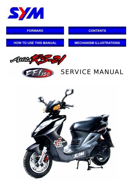
Sym Attila RS-21 EFI150 (HE15W) servicemanual - Scootergrisen
Sym Attila RS-21 EFI150 (HE15W) servicemanual - Scootergrisen
Sym Attila RS-21 EFI150 (HE15W) servicemanual - Scootergrisen

Create successful ePaper yourself
Turn your PDF publications into a flip-book with our unique Google optimized e-Paper software.
FORWARD CONTENTS<br />
HOW TO USE THIS MANUAL MECHANISM ILLUSTRATIONS<br />
SERVICE MANUAL
Model illustration<br />
Battery / fuse<br />
Winker relay<br />
Horn<br />
Engine control unit<br />
(ECU)<br />
Front winker light<br />
Rear<br />
brake<br />
lever<br />
Headlight<br />
Front brake<br />
lever<br />
Home page Contents<br />
Engine number<br />
Engine oil drain plug<br />
High & Low<br />
beam /<br />
Passing /<br />
Turn signal /<br />
Horn switch<br />
Engine temperature sensor<br />
Spark plug<br />
Crankshaft position sensor<br />
IG. Coil /<br />
Start relay /<br />
Fuel pump relay<br />
Fuel tank /<br />
Fuel pump<br />
Intake temperature<br />
& MAP sensor<br />
(T-MAP)<br />
Throttle position sensor (TPS) /<br />
Air by-pass valve /<br />
Fuel injector /<br />
Seat lock<br />
Tail light /<br />
Rear winker light<br />
Air cleaner<br />
Gear oil<br />
Inspection plug<br />
Gear oil drain<br />
plug<br />
Light /<br />
Starter switch<br />
Ignition switch<br />
Oil level<br />
Oil strainer<br />
Exhaust<br />
muffler
<strong>Sym</strong>bols And Marks.................. 1-1<br />
General safety ........................... 1-2<br />
Service Precautions.................. 1-3<br />
Specifications............................ 1-9<br />
Torque Values (Engine).......... 1-10<br />
<strong>Sym</strong>bols And Marks<br />
1. General Information/Trouble Diagnosis<br />
Torque Values (Frame) ........... 1-11<br />
Standard Torque Values for<br />
Reference................................. 1-11<br />
Troubles Diagnosis................. 1-12<br />
Parts To Be Greased............... 1-16<br />
<strong>Sym</strong>bols and marks are used in this manual to indicate what and where the special service are<br />
needed, in case supplemental information is procedures needed for these symbols and marks,<br />
explanations will be added to the text instead of using the symbols or marks.<br />
Warning<br />
Means that serious injury or even death may result if procedures are<br />
not followed.<br />
Caution<br />
Engine oil<br />
Means that equipment damages may result if procedures are not<br />
followed.<br />
Limits to use SAE 10W-30 API SG class oil. Warranty will not cover<br />
the damage that caused by not apply with the limited engine oil.<br />
(Recommended oil: KING MATE G-3 oil)<br />
Grease King Mate G-3 is recommended. (KING MATE G-3)<br />
Gear oil<br />
Locking sealant<br />
Home page Contents<br />
King Mate gear oil (SYM HYPOID GEAR OIL ) is recommended.<br />
(SAE 85W-140)<br />
Apply sealant, medium strength sealant should be used unless<br />
otherwise specified.<br />
Oil seal Apply with lubricant.<br />
Renew Replace with a new part before installation.<br />
Brake fluid Use recommended brake fluid “DOT3” or “WELLRUN” brake fluid.<br />
Special tools Special service tools.<br />
correct Meaning correct installation.<br />
wrong Meaning wrong installation.<br />
Indication Indication of components.<br />
directions Indicates position and operation directions.<br />
Components assembly directions each other.<br />
Indicates where the bolt installation direction, --- means that bolt<br />
cross through the component (invisibility).<br />
1-1<br />
1
1. General Information/Trouble Diagnosis<br />
General safety<br />
Carbon monoxide<br />
If you must run your engine, ensure the place is<br />
well ventilated. Never run your engine in a<br />
closed area. Run your engine in an open area, if<br />
you have to run your engine in a closed area, be<br />
sure to use an extractor.<br />
Caution<br />
Exhaust contains toxic gas which may cause<br />
one to lose consciousness and even result in<br />
death.<br />
Gasoline<br />
Gasoline is a low ignition point and explosive<br />
material. Work in a well-ventilated place, no<br />
flame or spark should be allowed in the work<br />
place or where gasoline is being stored.<br />
Caution<br />
Gasoline is highly flammable, and may<br />
explode under some conditions, keep it away<br />
from children.<br />
Used engine oil<br />
1-2<br />
Caution<br />
Prolonged contact with used engine oil (or<br />
transmission oil) may cause skin cancer<br />
although it might not be verdict.<br />
We recommend that you wash your hands<br />
with soap and water right after contacting.<br />
Keep the used oil beyond reach of children.<br />
Hot components<br />
Caution<br />
Components of the engine and exhaust<br />
system can become extremely hot after<br />
engine running. They remain very hot even<br />
after the engine has been stopped for some<br />
time. When performing service work on these<br />
parts, wear insulated gloves and wait until<br />
cooling off.<br />
This chapter Contents<br />
Battery<br />
Caution<br />
• Battery emits explosive gases; flame is<br />
strictly prohibited. Keep the place well<br />
ventilated when charging the battery.<br />
• Battery contains sulfuric acid (electrolyte)<br />
which can cause serious burns so be<br />
careful do not be spray on your eyes or<br />
skin. If you get battery acid on your skin,<br />
flush it off immediately with water. If you<br />
get battery acid in your eyes, flush it off<br />
immediately with water, then go to hospital<br />
to see an ophthalmologist.<br />
• If you swallow it by mistake, drink a lot of<br />
water or milk, and take some laxative such<br />
as castor oil or vegetable oil, and then go<br />
to see a doctor.<br />
• Keep electrolyte beyond reach of children.<br />
Brake shoe<br />
Do not use an compressed air or a dry brush to<br />
clean components of the brake system, use a<br />
vacuum cleaner or the equivalent to avoid<br />
asbestos dust flying.<br />
Caution<br />
Inhaling asbestos dust may cause disorders<br />
and cancer of the breathing system.<br />
Brake fluid<br />
Caution<br />
Spilling brake fluid on painted, plastic, or<br />
rubber parts may cause damage to the<br />
parts. Place a clean towel on the<br />
above-mentioned parts for protection when<br />
servicing the brake system. Keep brake fluid<br />
beyond reach of children.
Specifications<br />
DIMENSION<br />
WEIGHT<br />
ENGINE<br />
1. General Information/Trouble Diagnosis<br />
Maker SANYANG MODEL <strong>HE15W</strong><br />
Overall Length 1933 mm Suspension Front TELESCOPE<br />
Overall Width 700 mm<br />
System Rear UNlT SWING<br />
Overall Height 1160 mm Tire Front 100 / 90-12 (T/L)<br />
Wheel Base 1335 mm Specifications Rear 130 / 70 –12 (T/L)<br />
Curb<br />
Weight<br />
Front<br />
Rear<br />
Total<br />
48 kg<br />
75 kg<br />
123 kg<br />
Brake System<br />
Front<br />
Rear<br />
DISK (ø 273 mm)<br />
DISK (ø 200 mm)<br />
Passengers/<br />
Weight<br />
Front<br />
Two /110 kg<br />
78 kg<br />
PERFOR<br />
MANCE<br />
Max. Speed<br />
Climb Ability<br />
100 km/hr Above<br />
28° Below<br />
Total<br />
Weight<br />
Cylinder<br />
Rear 155 kg<br />
Total 233 kg<br />
Primary<br />
Reduction<br />
Secondary<br />
Reduction<br />
BELT<br />
GEAR<br />
Type 4-STROKE ENGINE Clutch Centrifugal, dry type<br />
Installation and<br />
arrangement<br />
Vertical, below center,<br />
incline 80°<br />
Reduction<br />
Transmission C.V.T.<br />
Fuel Used Unleaded Speedometer 0 ~ 140 km/hr<br />
Cycle/Cooling<br />
4-stroke/forced air<br />
cooled<br />
Horn 70~90 dB/A<br />
Bore 57.4 mm Muffler Expansion & Pulse Type<br />
Stroke 57.8 mm<br />
Number/Arran<br />
gement<br />
Displacement 149.5 cc<br />
Compression<br />
Ratio<br />
Max. HP 12.4 ps / 8500 rpm<br />
Exhaust Pipe Position<br />
and Direction<br />
Right side, and<br />
Backward<br />
Single Cylinder Lubrication System Separated-lubrication<br />
Exhaust<br />
Concentration<br />
Solid<br />
Particulate<br />
9.6 : 1 CO Below 4 %<br />
HC Below 2000 ppm<br />
Max. Torque 1.15 kg-m / 6500 rpm E.E.C. YES<br />
Ignition C.D.I. P.C.V. YES<br />
Starting System Power & Foot<br />
This chapter Contents<br />
Catalytic reaction<br />
control system<br />
-<br />
NO<br />
1-9
1. General Information/Trouble Diagnosis<br />
Torque Values (Engine)<br />
1-10<br />
Item Q’ty<br />
Thread Dia.<br />
(mm)<br />
Torque<br />
Value(Kg-m)<br />
Cylinder head bolts 4 6 1.0~1.4<br />
Cylinder head nuts 4 8 2.0~2.4<br />
Cylinder/cylinder head two-ends<br />
bolts<br />
Remarks<br />
4 8 0.7~1.1 Tighten to crankcase<br />
Cylinder head left bolts 4 6 1.0~1.4<br />
Valve adjustment fixing nuts 4 5 0.7~1.1 Apply oil to thread<br />
Cylinder head left cover bolts 2 6 1.0~1.4<br />
Spark plug 1 10 1.0~1.2<br />
Carburetor heat protector<br />
connecting nuts<br />
2 6 0.7~1.1<br />
Engine oil draining plug 1 12 3.5~4.5<br />
Engine oil strainer cap 1 30 1.0~2.0<br />
Gear oil draining plug 1 8 0.8~1.2<br />
Gear oil filling bolt 1 10 1.0~1.4<br />
Oil pump screws 3 3 0.1~0.3<br />
Engine left side cover bolts 8 6 1.0~1.5 Rubber washer attached<br />
Camshaft chain tensioner bolt 1 6 0.35~0.5 Hex socket bolt<br />
Camshaft chain adjuster bolts 1 6 0.8~1.2<br />
Clutch driving plate nut 1 28 5.0~6.0<br />
Clutch outer bracket nut 1 12 5.0~6.0<br />
Driving disk nut 1 12 5.0~6.0<br />
Flywheel nut 1 12 5.0~6.0<br />
One-way clutch tighten bolts 3 6 1.0~1.4 Apply locking sealant<br />
One-way clutch nut 1 22 9.0~10.0 Apply oil to thread<br />
Crankcase bolts/right crank<br />
cover bolt<br />
This chapter Contents<br />
12 8 1.5~2.0<br />
Gear box cap bolts 7 8 2.0~2.4<br />
Exhaust pipe bolts 2 8 3.0~3.6<br />
Exhaust pipe connection nut 2 7 0.5~1.0
B. Engine run sluggish (Speed does not pick up, lack of power)<br />
1. General Information/Trouble Diagnosis<br />
Check and adjustment Fault condition Probable causes<br />
Try gradual acceleration<br />
and check engine speed<br />
Engine speed can be<br />
increased.<br />
Check ignition timing<br />
(Using ignition lamp)<br />
Check cylinder<br />
compression pressure<br />
(using compression<br />
pressure gauge)<br />
Engine speed can not<br />
be increased.<br />
Ignition timing correct Incorrect ignition timing<br />
Compression pressure<br />
correct<br />
Check if fuel injector is<br />
clogged<br />
Remove spark plug<br />
Check if engine over heat<br />
Continually drive in<br />
acceleration or high<br />
speed<br />
No compression<br />
pressure<br />
No clogged Clogged<br />
No foul or discoloration<br />
This chapter Contents<br />
Fouled and discoloration<br />
Normal Engine overheat<br />
No knock Knock<br />
1. Air cleaner clogged<br />
2. Poor fuel supply<br />
3. Lines in fuel tank evaporation system<br />
clogged<br />
4. Exhaust pipe clogged<br />
5. Fuel injector clogged<br />
1. Malfunction of ECU<br />
2. Malfunction of AC alternator<br />
1. Cylinder & piston ring worn out<br />
2. Cylinder gasket leaked<br />
3. Sand hole in compression parts<br />
4. Valve deterioration<br />
5. Seized piston ring<br />
1. Replace fuel injector<br />
1. Remove dirt<br />
2. Incorrect spark plug heat range<br />
1. Piston and cylinder worn out<br />
2. Injector clogged<br />
3. Poor fuel quality<br />
4. Too much carbon deposited in<br />
combustion chamber<br />
5. Ignition timing too advanced<br />
1. Too much carbon deposited in<br />
combustion chamber<br />
2. Malfunction of fuel injector<br />
3. Poor fuel quality<br />
4. Ignition timing too advanced<br />
1-13
E. Clutch, driving and driving pulley<br />
Engine can be started but<br />
motorcycle can not be moved.<br />
1. General Information/Trouble Diagnosis<br />
FAULT CONDITIONS PROBABLE CAUSES<br />
Engine running and misfire as<br />
motorcycle initial forward moving<br />
or jumping suddenly (rear wheel<br />
rotating as engine in running)<br />
Poor initial driving ( Poor climbing<br />
performance)<br />
This chapter Contents<br />
1. Drive belt worn out or deformation<br />
2. Ramp plate of movable drive face damaged<br />
3. Driving pulley spring broken<br />
4. Clutch weights broken<br />
5. Drive slide-shaft gear groove broken<br />
6. Transmission gear damaged<br />
1. Clutch weights spring broken<br />
2. Clutch outer stuck with clutch weights<br />
3. Connection parts in clutch and shaft worn out or<br />
burned<br />
1. Drive belt worn out or deformation<br />
2. Weight roller worn out<br />
3. Movable drive face shaft worn out<br />
4. Driven pulley spring deformation<br />
5. Driven pulley shaft worn out<br />
6. Greased in drive belt and driven face.<br />
1-15
1. General Information/Trouble Diagnosis<br />
Parts To Be Greased<br />
1-16<br />
Acceleration cable/ Front & rear<br />
brake lever pivot<br />
Steering shaft bearing Seat lock<br />
Speedometer gear/<br />
front wheel bearing<br />
This chapter Contents<br />
Side stand pivot<br />
Main stand pivot<br />
Rear wheel bearing
Precautions In Operation .......... 2-1<br />
Periodical Maintenance<br />
Schedule ..................................... 2-2<br />
Lubrication System.................... 2-3<br />
Gear Oil ....................................... 2-4<br />
Fuel System................................ 2-4<br />
Air Cleaner.................................. 2-5<br />
Throttle Valve Operation ........... 2-5<br />
Crankcase Ventilation ............... 2-6<br />
Valve Clearance Adjustment..... 2-6<br />
Valve Clearance Inspection<br />
And Adjustment ......................... 2-7<br />
Idle Speed / Exhaust Gas<br />
Adjustment ................................. 2-7<br />
Ignition System .......................... 2-8<br />
Precautions In Operation<br />
Home page Contents<br />
2. Maintenance Information<br />
Spark Plug .................................. 2-8<br />
Cylinder Compression<br />
Pressure...................................... 2-9<br />
Driving System ........................... 2-9<br />
Steering System ....................... 2-10<br />
Suspension System ................. 2-10<br />
Disk Brake System (Front/Rear<br />
Disk Brake) ............................... 2-11<br />
Wheel / Tire............................... 2-13<br />
Battery....................................... 2-14<br />
Headlamp Adjustment ............. 2-14<br />
Nuts, Bolts Tighteness ............ 2-14<br />
Special Service Tools<br />
Catalogue.................................. 2-15<br />
Specification<br />
Fuel Tank Capacity 6100 c.c.<br />
Engine Oil<br />
Capacity<br />
Change<br />
1000 c.c.<br />
800 c.c.<br />
Transmission Gear oil<br />
Capacity<br />
Change<br />
110 c.c.<br />
100 c.c.<br />
Clearance of throttle valve 2~6 mm<br />
Spark plug NGK CR8E Gap: 0.8 mm<br />
“F” Mark in idling speed BTDC 13º / 1600 rpm<br />
Full timing advanced BTDC 34º / 8000 rpm<br />
Idling speed 1600±100 rpm<br />
Cylinder compression pressure 12 ± 2 kgf/cm²<br />
Valve clearance: IN/EX 0.12 ± 0.02 mm<br />
Tire dimension<br />
Front<br />
Rear<br />
100/90-12 59J (T/L)<br />
130/70-12 59J (T/L)<br />
Tire pressure (cold)<br />
Single<br />
Two persons<br />
Front: 1.75 kg/cm² rear : 2.25 kg/cm²<br />
Front: 1.75 kg/cm² rear : 2.50 kg/cm²<br />
Battery 12V8Ah (MF battery) type: YTX9A-BS (8Hr)<br />
2-1<br />
2
Lubrication System<br />
Engine Oil Capacity<br />
Caution<br />
• The vehicle must be parked on a level<br />
ground when checking oil capacity.<br />
• Run the engine for 3-5 minutes then stop,<br />
wait about 3-5 more minutes allowing<br />
engine oil to settle before checking the oil<br />
level.<br />
Remove dipstick to check the oil level. If oil level<br />
is below the lower limit mark, add oil to the<br />
specified upper limit mark.<br />
Engine Oil change<br />
Shut off the engine and remove dipstick.<br />
Remove the oil drain plug on the bottom-left of<br />
crankcase to drain oil.<br />
After draining out oil, clean oil plug and its gasket<br />
and reinstall. Replace the gasket if it is damaged.<br />
Torque value: 3.5~4.5 kgf-m<br />
Caution<br />
Warm up the engine. This will make the oil<br />
flow out easily.<br />
Add oil to the specified capacity.<br />
Oil Viscosity: SAE 10W-30, or equivalent<br />
recommended using King-Mate serial oil.<br />
Engine oil capacity: Disassembly: 1050cc<br />
Change: 800cc<br />
When checking for oil leak, run the engine at idle<br />
speed for a few minutes, then check oil capacity<br />
with dipstick.<br />
Cleaning the oil strainer<br />
Drain oil from engine, remove the strainer cover,<br />
spring and strainer.<br />
If there is an accumulation on the screen, wash it<br />
off with suitable solvent (recommended using<br />
compressed air to cleaning the foreign).<br />
Check O-ring for damage, replace if necessary.<br />
Reinstall strainer, spring, O-ring and strainer<br />
cover.<br />
Torque value: 1.3~1.7 kgf-m<br />
This chapter Contents<br />
2. Maintenance Information<br />
Oil drain plug<br />
2-3
2. Maintenance Information<br />
Gear Oil<br />
Inspection<br />
Check gear oil if leaking.<br />
Park the motorcycle with main stand on flat level<br />
place.<br />
Turn off engine and remove the gear oil draining<br />
plug.<br />
Place a measurement cup under the draining<br />
hole.<br />
Check gear oil if enough.<br />
Replacement<br />
At first, remove the gear oil refilling bolt, and then<br />
remove the draining plug.<br />
Install the draining plug after drained oil out.<br />
Torque value: 0.8~1.2 kgf-m<br />
2-4<br />
Caution<br />
Inspect if washer is in good condition.<br />
Replace it with new one if it was deformed or<br />
damaged.<br />
Fill out specified gear oil from the engine oil filling<br />
opening.<br />
Install the oil filling bolt.<br />
Torque value: 1.0~1.4 kgf-m<br />
Quantity: 100 c.c.<br />
Recommended: King-Mate HYPOID GEAR OIL<br />
(#140)<br />
Fuel System<br />
Fuel Lines<br />
Remove luggage box, rear carrier, body covers.<br />
Check all lines, and replace it when they are<br />
deterioration, damage or leaking.<br />
Warning<br />
Gasoline is a low ignition material so any kind<br />
of fire is strictly prohibited as dealing it.<br />
Fuel filter<br />
Remove luggage box, rear carrier, body covers.<br />
Remove fuel pump and fuel unit assembly.<br />
Check if the fuel filter is clogged, broken. If so,<br />
clean or replace the fuel filter with new one.<br />
Caution<br />
The arrow on the fuel pump and fuel sender<br />
mean the assembly direction of fuel tank,<br />
check if it is in corrective installation.<br />
This chapter Contents<br />
Gear oil<br />
refilling bolt<br />
Gear oil draining plug<br />
Fuel pipes<br />
Fuel filter
Cylinder Compression Pressure<br />
Warn up engine and then turn off the engine.<br />
Remove the trunk and the central cover.<br />
Remove spark plug cap and spark plug.<br />
Install compression gauge.<br />
Full open the throttle valve, and rotate the engine<br />
by means of stepping the foot-starting lever.<br />
Caution<br />
Rotate the engine until the reading in the<br />
gauge no more increasing.<br />
Usually, the highest pressure reading will be<br />
obtained in 4~7 seconds.<br />
Compression pressure: 12 ± 2 Kg/cm²<br />
Check following items if the pressure is too low:<br />
• Incorrect valve clearance<br />
• Valve leaking<br />
• Cylinder head leaking, piston, piston ring and<br />
cylinder worn out<br />
If the pressure is too high, it means carbon<br />
deposits in combustion chamber or piston head.<br />
Driving System<br />
Drive Belt<br />
Remove left side cover.<br />
Remove mounting bolt located under air cleaner.<br />
Remove 9 bolts of the engine left side cover and<br />
the cover.<br />
Check if the belt is crack or worn out.<br />
Replace the belt if necessary or in accord with<br />
the periodical maintenance schedule to replace<br />
it.<br />
Width limit: 18.5mm or more<br />
Clutch Pad<br />
Start the motorcycle and gradually increase<br />
throttle valve openness to check clutch pad<br />
operation.<br />
If the motorcycle moves with shaking, then check<br />
its clutch pad for wearing. Replace it if<br />
necessary.<br />
This chapter Contents<br />
2. Maintenance Information<br />
Spark plug<br />
Gear teeth<br />
Clutch pad<br />
Width<br />
Cylinder<br />
pressure<br />
gauge<br />
Clutch<br />
2-9
2. Maintenance Information<br />
Steering System<br />
2-10<br />
Caution<br />
Check all wires and cables if they are<br />
interfered with the rotation of steering handle<br />
bar.<br />
Lift the front wheel out of ground.<br />
Turn handle from right to left alternative and<br />
check if turning is smoothly.<br />
If handle turning is uneven and bending, or the<br />
handle can be operated in vertical direction, then<br />
adjust the handle top bearing.<br />
Suspension System<br />
Warning<br />
• Do not ride the motorcycle with poor shock<br />
absorber.<br />
• Looseness, wear or damage shock<br />
absorber will make poor stability and drive<br />
ability.<br />
Front shock absorber<br />
Hold front brake lever and press down the front<br />
shock absorber for several times to check its<br />
operation.<br />
Hold front brake lever and push forward the front<br />
shock absorber for several times to check its<br />
locking status.<br />
Check if it is scratched or leaking.<br />
Replace damaged and non-repairable<br />
components.<br />
Tighten all nuts and bolts.<br />
Rear Shock absorber<br />
Press down the rear shock absorber for several<br />
times to check its operation.<br />
Check if it is scratched or leaking.<br />
Replace damaged and non-repairable<br />
components.<br />
Park the motorcycle with main standard.<br />
Start engine and let the rear wheel rotate after<br />
increased engine rpm. Check engine for any<br />
parts loose or shaking. Also check the engine<br />
suspension bushing for wear out. Replace the<br />
bushing if worn out.<br />
Tighten all nuts and bolts.<br />
This chapter Contents
Disk Brake System (Front/Rear Disk<br />
Brake)<br />
Brake System Metal Hoses<br />
Make sure the brake metal hoses for corrosion or<br />
leaking oil, and also check brake system for<br />
leaking.<br />
Brake Fluid<br />
Check brake fluid level in the brake fluid reservoir.<br />
If the level is lower than the LOWER limit, add<br />
brake fluid to UPPER limit. Also check brake<br />
system for leaking if low brake level found.<br />
Caution<br />
In order to maintain brake fluid in the reservoir<br />
in horizontal position, do not remove the cap<br />
until handle bar stop.<br />
Do not operate the brake lever after the cap<br />
had been removed. Otherwise, the brake<br />
fluid will spread out if operated the lever.<br />
Do not mix non-compatible brake fluid<br />
together.<br />
Filling Out Brake Fluid<br />
Tighten the drain valve, and add brake fluid.<br />
Place the diaphragm in.<br />
Operate the brake lever so that brake fluid<br />
contents inside the brake system hoses.<br />
Air Bleed Operation<br />
Connect a transparent hose to draining valve.<br />
Hold the brake lever and open air bleeding valve.<br />
Perform this operation alternative until there is no<br />
air inside the brake system hoses.<br />
Caution<br />
Before closing the air bleed valve, do not<br />
release the brake lever.<br />
Added Brake Fluid<br />
Add brake fluid to UPPER limit lever.<br />
Recommended brake fluid: DOT3 or DOT4<br />
WELL RUN brake fluid.<br />
Caution<br />
Never mix or use dirty brake fluid to prevent<br />
from damage brake system or reducing brake<br />
performance.<br />
This chapter Contents<br />
Lower limit<br />
Bubbles<br />
2. Maintenance Information<br />
Brake metals hose<br />
Screws<br />
Master cylinder cap<br />
Diaphragm plate<br />
Diaphragm<br />
Upper limit<br />
Draining valve<br />
Master<br />
cylinder<br />
cap<br />
Transparent draining hose<br />
2-11
2. Maintenance Information<br />
Battery<br />
Battery Removal<br />
Remove right cover. (3 screws)<br />
Battery cables removal:<br />
1. At first, remove the negative “-” cable.<br />
2. Then, remove the positive “+” cable.<br />
3. Remove the battery.<br />
If there is some rust on battery posts, clean it<br />
with steel brush.<br />
Install the battery in the reverse procedures of<br />
removal.<br />
2-14<br />
Caution<br />
• If there is rust on the posts very serious,<br />
spray some hot water on the posts.<br />
Then, clean it with steel brush so that<br />
can remove rust for more easily.<br />
• Apply some grease on the posts after<br />
rust removed to prevent from rust again.<br />
Headlamp Adjustment<br />
Headlamp adjustment<br />
Remove the front fender.<br />
Turn the headlamp adjustment screw to adjust<br />
headlamp beam height. (C.W. is for increasing<br />
beam height, and C.C.W. is for decreasing beam<br />
height)<br />
Reinstall the front fender.<br />
Caution<br />
• To adjust the headlamp beam follows<br />
related regulations. Do not adjust it<br />
arbitrarily if not necessary.<br />
• Improper headlamp beam adjustment will<br />
make in coming driver dazzled or<br />
insufficient lighting.<br />
Nuts, Bolts Tighteness<br />
Perform periodical maintenance in accord with<br />
the Periodical Maintenance Schedule.<br />
Check if all bolts and nuts on the frame are<br />
tightened securely.<br />
Check all fixing pins, snap rings, hose (pipe)<br />
clamps, and wire holders for security.<br />
This chapter Contents<br />
Headlamp adjustment screw
Mechanism Illustration .............. 3-1<br />
Operational Precautions:........... 3-2<br />
Trouble Diagnosis...................... 3-2<br />
Engine Oil ................................... 3-3<br />
Cleaning Engine Oil Strainer..... 3-3<br />
Oil Pump Removal ..................... 3-4<br />
Mechanism Illustration<br />
Rock Arm<br />
Scoop lubrication<br />
Connecting rod<br />
Forcedly lubrication<br />
Crankshaft<br />
Oil strainer<br />
Home page Contents<br />
3. Lubrication System<br />
Oil Pump Disassembly .............. 3-4<br />
Oil Pump Inspection .................. 3-5<br />
Oil Pump Re-assembly.............. 3-5<br />
Oil Pump Installation ................. 3-6<br />
Gear Oil....................................... 3-7<br />
Forcedly lubrication<br />
Cam Shaft<br />
Inner passage<br />
Oil pump<br />
3-1<br />
3
3. Lubrication System<br />
Operational Precautions:<br />
General Information<br />
This chapter contains maintenance operations for the engine oil pump, engine oil and gear oil.<br />
Specifications<br />
Engine oil quantity Disassembly 1000 c.c.<br />
Replacement 800 c.c<br />
Oil viscosity<br />
Oil viscosity SAE 10W-30 or equivalent<br />
(Recommended King-Mate<br />
serial oils)<br />
Gear Oil Disassembly 110 c.c.<br />
Replacement 100 c.c.<br />
Oil viscosity of gear oil SAE 85W-140<br />
(Recommended King-Mate<br />
gear oil series SYM<br />
HYPOID GEAR OIL)<br />
Oil pump<br />
3-2<br />
Items Standard (mm) Limit (mm)<br />
Inner rotor clearance - 0.12<br />
Clearance between outer rotor and body - 0.12<br />
Clearance between rotor side and body 0.05~0.10 0.20<br />
Torque value<br />
Engine oil drain plug 3.5~4.5 kgf-m<br />
Engine oil filter cover 1.3~1.7 kgf-m<br />
Gear oil drain plug 0.8~1.2 kgf-m<br />
Gear oil filling bolt 1.0~1.4 kgf-m<br />
Oil pump connection screw 0.1~0.3 kgf-m<br />
Trouble Diagnosis<br />
Low engine oil level<br />
• Oil leaking<br />
• Valve guide or seat worn out<br />
• Piston ring worn out<br />
Low Oil Pressure<br />
• Low engine oil level<br />
• Clogged in oil strainer, circuits or pipes<br />
• Oil pump damage<br />
This chapter Contents<br />
Dirty oil<br />
• No oil change in periodical<br />
• Cylinder head gasket damage<br />
• Piston ring worn out<br />
unit: mm
Engine Oil<br />
Turn off engine, and park the motorcycle in flat<br />
surface with main stand. Check oil level with oil<br />
dipstick after 3-5 minutes.<br />
Do not screw the dipstick into engine as<br />
checking.<br />
If oil level is nearly low level, fill out<br />
recommended oil to upper level.<br />
Oil Replacement<br />
Caution<br />
Drain oil as engine warmed up so that make<br />
sure oil can be drained smoothly and<br />
completely.<br />
Place an oil pan under the motorcycle, and<br />
remove oil strainer cap.<br />
Make sure if the aluminum washer of the<br />
draining bolt is damaged. If so, replace it with<br />
new one.<br />
Install the drain bolt and tighten it.<br />
Torque value: 3.5~4.5 kgf-m<br />
Cleaning Engine Oil Strainer<br />
Remove the oil strainer cap.<br />
Remove oil strainer and spring.<br />
Clean oil strainer. (Recommended using<br />
compressed air to clean dirty foreign.)<br />
Check if the strainer and O-ring of the oil strainer<br />
are broken. Replace with new one if found.<br />
Install the oil strainer and spring.<br />
Install the oil strainer cap and tighten it.<br />
Torque value: 1.3~1.7 kgf-m<br />
Fill out oil to the oil filler. (Oil viscosity SAE<br />
10W-30) (Recommended King-Mate serial oils)<br />
Engine oil quantity: Replacement 800 c.c.<br />
After oil replaced, insert ignition key into the<br />
re-set bottom under instrument panel so that the<br />
oil indicator is changed from red to green and set<br />
oil replacement mileage to zero.<br />
Install dipstick, start the engine for running<br />
several minutes.<br />
Turn off engine, and check oil level again if within<br />
standard level after 3-5 minutes.<br />
Check if engine oil leaks.<br />
This chapter Contents<br />
Oil stick<br />
Oil filter cover<br />
3. Lubrication System<br />
Drain plug<br />
3-3
3. Lubrication System<br />
Install driving gear and clamp.<br />
3-6<br />
Caution<br />
Install the oil pump cover and fixing pin<br />
properly.<br />
Oil Pump Installation<br />
Install the oil pump (3 screws).<br />
Caution<br />
The elliptical hole on the driving gear is not<br />
match with the screw hole. Thus, the elliptical<br />
hole has to align with the screw hoe before<br />
tightening it.<br />
Install oil pump outer cover (2 bolts).<br />
Install the starting gear and the alternator.<br />
(Refer to chapter 10)<br />
This chapter Contents<br />
2 screws<br />
3 screws
Mechanism Illustration ...............4-1<br />
EFI System Components............4-2<br />
Introduction Of Fuel Control<br />
System .........................................4-3<br />
Electronical Fuel Injection<br />
Components & Operation Principle<br />
Introduction .................................4-3<br />
Precautions In Operation ...........4-4<br />
Trouble Diagnosis.......................4-5<br />
Components Description Of Efi.4-9<br />
Fuel Lines ..................................4-11<br />
Ignition System .........................4-12<br />
Crank Position Sensor..............4-13<br />
Temperature Sensor .................4-14<br />
Mechanism Illustration<br />
Battery<br />
Engine temperature sensor<br />
Ignition coil<br />
Fuel<br />
injector<br />
Home page Contents<br />
Throttle position<br />
sensor (TPS)<br />
Data Scan<br />
(Diagnosisor)<br />
Air by-pass valve<br />
4. FUEL INJECTION SYSTEM<br />
Air By-pass Valve......................4-15<br />
Fuel Injector...............................4-15<br />
Fuel Pump..................................4-15<br />
Fuel Tank ...................................4-16<br />
Air Cleaner .................................4-19<br />
Trouble Diagnosis & Solutions Of<br />
EFi...............................................4-20<br />
Error Code Message and Solution<br />
Operation ...................................4-<strong>21</strong><br />
EFi Data scan Operation Manual<br />
....................................................4-23<br />
EFi Component Malfunction<br />
Check& Replacement<br />
Procedure (PI Engine)............4-36<br />
Hazardous lamp<br />
Crankshaft position sensor<br />
ECU<br />
Fuel pump & pressure regulator<br />
Fuel<br />
tank<br />
Vacuum hose<br />
Intake temperature &<br />
MAP sensor<br />
(T-MAP)<br />
4-1<br />
4
This chapter Contents<br />
4. FUEL INJECTION SYSTEM<br />
Introduction Of Fuel Control System<br />
The engine of this model was based on a 150 c.c. four-stroke & 4-valve SOHC electronic controlled<br />
single cylinder, air-cooler, engine. It adopts a charcoal canister to absorb the fuel vapor generated<br />
through evaporation in the fuel system & crankcase. Then, introducing evapor into combustion<br />
chamber.<br />
Electronic Fuel Injection Device:<br />
This device consists of both the fuel supply system ---fuel tank, electrical fuel pump, fuel filter, and<br />
fuel pump regulator as well and the fuel control system---fuel injector and ECU.<br />
Fuel is delivered to the fuel injector onto the intake manifold through fuel tank to fuel pump. Fuel<br />
pressure is kept within 2.5bar by means of the fuel regulator. Then, the injection signal from ECU is<br />
to let fuel inject to cylinder in every crankshaft rotation. In addition, the residual fuel is back to fuel<br />
tank by the fuel regulator. The fuel pump is stalled into the fuel tank so that can reduce noise and<br />
simplify the fuel pipe routing. The electronic controlled ignition & injection system can control fuel<br />
consumption & emission efficiently so that reaches to the purpose of environmental purification.<br />
Fuel delivery way in most of motorcycle’s engines is by carburetor. The absorption capacity of engine<br />
is to create vacuum inside of the carburetor so that fuel is suck into combustion chamber with air.<br />
Therefore, under such operation, air & fuel mixture ratio is decided by flowing air and fuel absorbed<br />
quantity. Thus, the 3 factors, air detective quantity, fuel quantity decision and fuel absorbed quantity,<br />
are conducted inside of the carburetor.<br />
However, as for the fuel injection system, it detects air absorbed quantity and temperature. Thus, the<br />
fuel supply quantity is decided by the default preset in the system computer. Then, fuel is injected out<br />
by the fuel injector. Comparing with carburetor engine, the 3 factors are independent, and can<br />
increase their precision easily so that fuel supply can be much more accurate.<br />
The engine is equipped with a fuel injection of computerized control and its main characters are as<br />
following:<br />
1. The necessary fuel injection quantity is decided by correspondence with engine rotation. And, the<br />
engine also is applied with a good reaction and high accurate throttle valve. (So, fuel injection<br />
quantity and timing are decided by engine RPM and the throttle valve opening.)<br />
2. The decision of fuel injection quantity and injection timing are controlled by a 8-bite highly<br />
accurate micro-computer.<br />
3. The pressure regulator is always to keep the variances of intake manifold and fuel pressures in a<br />
constant value (2.5bar). So, with the change of intake manifold pressure, the fuel injection quantity<br />
can be kept in proper level.<br />
4. The engine can measure the manifold pressure to enrich fuel injection based on high position<br />
level so that enhance driving capacity.<br />
5. The idle speed control system is to provide manifold with the 2 nd air to increase idle speed’s<br />
stability and starting capacity.<br />
Electronical Fuel Injection Components & Operation Principle Introduction<br />
The electronic fuel injection components is consists of both the fuel supply system ---fuel tank,<br />
electrical fuel pump, fuel filter, and fuel pump regulator as well and the fuel control system---fuel<br />
injector and ECU.<br />
Fuel is delivered to the fuel injector onto the intake manifold through fuel tank to fuel pump. Fuel<br />
pressure is kept within 2.5bar by means of the fuel regulator. Then, the injection signal from ECU is<br />
to let fuel inject to cylinder in every crankshaft rotation (i.e. the fuel supply system is to inject fuel to<br />
cylinder one time. In addition, the residual fuel is back to fuel tank by the fuel regulator through the<br />
fuel return pipe. In order to reduce noise and simplify the fuel pipe routing the fuel pump usually is<br />
designed to install into the fuel tank.<br />
Generally speaking, the electronic controlled ignition & fuel injection system can control fuel<br />
consumption & emission efficiently so that reaches to the purpose of environmental purification.<br />
4-3
Trouble Diagnosis<br />
EFI Electrical Circuit Inspection<br />
Does the warning lamp goes on for 2 seconds<br />
and then off?<br />
Battery voltage over 12.5V?<br />
The voltage difference between battery and<br />
ECU is less than 0.2V.<br />
1. Turn off the ignition switch.<br />
2. Disconnect the ECU connector.<br />
3. Turn on the ignition switch.<br />
4. With a multi-meter to measure the voltage<br />
between the 17 th pin(+) and the 1 st pin (-).<br />
5. Make sure the voltage difference between<br />
battery and ECU is less than 0.2V.<br />
The voltage difference between battery and<br />
active components is less than 0.2V.<br />
1. Turn off the ignition switch.<br />
2. Disconnect the connectors of the fuel<br />
injector, by-pass valve, and ignition coil.<br />
3. Measure the voltage between battery<br />
negative side and the each connector (1).<br />
4. Make sure the voltage difference between<br />
battery and those active components is<br />
less than 0.2V.<br />
The voltage difference between 5V-sensors is<br />
less than 0.2V.<br />
1. Turn off the ignition switch.<br />
2. Disconnect the connectors of throttle valve<br />
position sensor and intake manifold<br />
temperature/pressure sensors.<br />
3. Turn on the ignition switch.<br />
4. Measure the voltage between the<br />
pins(1)(4) of throttle valve position, and the<br />
pins of intake manifold<br />
temperature/pressure sensors (1) (3) is<br />
within 5V±0.2V.<br />
The voltage difference between battery and<br />
fuel pump is less than 0.2V.<br />
1. Turn off the ignition switch.<br />
2. Disconnect the fuel pump connector.<br />
3. With the probes of multi-meter to touch the<br />
positive & negative sides of the fuel pump.<br />
4. Turn on the ignition switch.<br />
5. Record the voltage difference of the fuel<br />
pump within 3 seconds.<br />
6. Make sure the voltage difference between<br />
battery and fuel pump is less than 0.2V.<br />
This chapter Contents<br />
4. FUEL INJECTION SYSTEM<br />
Turn on the ignition switch.<br />
OK<br />
OK<br />
OK<br />
OK<br />
OK<br />
OK<br />
END<br />
NG<br />
NG<br />
NG<br />
NG<br />
NG<br />
NG<br />
1. Burnt Bulb?<br />
2. Blown fuse?<br />
3. Battery voltage too low?<br />
4. Poor wire contact on ECU<br />
circuit?<br />
5. Poor contact on the master<br />
switch?<br />
6. Malfunction of ECU?<br />
1. abnormal charging circuit?<br />
2. Battery cannot be<br />
charged?<br />
3. Short wire circuit?<br />
1. abnormal wire connection?<br />
1. abnormal wire connection ?<br />
1. abnormal wire connection?<br />
2. Malfunction of ECU?<br />
1. abnormal wire connection?<br />
2. Malfunction of relay?<br />
3. Malfunction of ECU?<br />
4-5
Diagnosis Of Idle Speed Misfire<br />
Idle speed misfire<br />
1. Connect the Data Scan<br />
and check trouble content<br />
2. Troubleshooting<br />
according to the<br />
troubleshooting<br />
procedure.<br />
Is fuel enough?<br />
Are the battery wires<br />
loose?<br />
Is the vacuum hose<br />
leaking?<br />
This chapter Contents<br />
4. FUEL INJECTION SYSTEM<br />
Does the throttle valve<br />
cable stuck so could<br />
not be set-up?<br />
Is the CO value in idle<br />
speed out of set up<br />
range? (0.5%~3.0%)<br />
Does the carbon<br />
deposited onto the throttle<br />
valve body?<br />
Does the by-pass valve<br />
operate or out of order?<br />
If the idle speed misfire<br />
problem still can not be solved<br />
after check above related EFI<br />
components item by item,<br />
then check if the other<br />
traditional components on the<br />
engine is in abnormal.<br />
Connect the Data Scan<br />
and enter into CO<br />
adjustment at idle<br />
menu. Positive value is<br />
for enrichment, and<br />
negative value is for<br />
lean.<br />
Replace with<br />
new one for<br />
confirmation<br />
4-7
Fuel Lines<br />
Fuel injector<br />
This chapter Contents<br />
4. FUEL INJECTION SYSTEM<br />
Fuel filter<br />
Vacuum hose<br />
Battery<br />
System Description:<br />
1. All sensors’ signals sent to the ECU firstly after the electrical fuel pump inside the fuel tank key-on.<br />
Then, ECU controls the fuel pump relay so let the pump operate. If the engine did not start for<br />
2~3 seconds, then the fuel pump will be turned off to save power. The pressure regulator is to<br />
maintain the fuel pressure in 2.5bar, and the fuel injector inject properly fuel quantity according to<br />
running conditions and environmental corrective coefficient. When key-off or engine stopped, the<br />
fuel pump stops operating.<br />
2. The fuel filter is to filter foreign materials so it has to be replaced regularly.<br />
3. Do not let the starting motor keep running when the engine can not be started in smoothly to<br />
cause battery voltage insufficient (under 8V) and the pump will not be operated. The corrective<br />
method is to start the engine by connecting a new battery or with foot-lever.<br />
ECU<br />
Fuel tank<br />
Fuel pump & pressure regulator<br />
4-11
Crank Position Sensor<br />
The magnetic field type sensor is to induct a<br />
voltage signal to calculate engine speed with<br />
ACG gear ring (24-1 tooth).<br />
There is one tooth in every 15 degree on the<br />
gear ring. But, one of teeth is flatted to be TDC<br />
base.<br />
ECU signal<br />
Secondary<br />
voltage<br />
This chapter Contents<br />
Closed<br />
Flywheel<br />
gear ring<br />
sensor’s signal Time<br />
4. FUEL INJECTION SYSTEM<br />
No teeth<br />
TDC Ignition<br />
TDC<br />
Description:<br />
The ECU that received all sensors’ signals to control the throttle valve openness with PWM so that<br />
can adjust air-flow into the by-pass valve of the intake manifold. And then adjust idle speed and have<br />
a stable and normal running engine.<br />
1. When engine starting---the by-pass valve open for a while to increase air-flow and then enhance<br />
engine idle speed to prevent from unstable engine running and misfired within initial starting.<br />
2. Warm-up---when engine oil is in low temperature condition, the by-pass valve adjusts air-flow<br />
according to engine temperature (engine oil temperature) so that have a fast idle speed.<br />
3. Speed Decreasing---with the ECU controlling, the by-pass valve also corresponds with<br />
acceleration operation to provide intake manifold with proper air-flow quantity. Such operation<br />
will let engine rpm reduce slowly to prevent from engine misfired, negative pressure in intake<br />
manifold increasing, and then to reduce HC emission.<br />
4-13
4. FUEL INJECTION SYSTEM<br />
Temperature Sensor<br />
Engine oil temperature sensor: According to the semiconductor’s variable character, the sensor<br />
detects the change of engine oil and metal wall and then transferred<br />
into a voltage signal sending to the ECU. Then, the ECU corrects fuel<br />
injection and ignition timing.<br />
Intake temperature and pressure sensor: a sensor that is combined both pressure and NTC can<br />
detect the absolute pressure and temperature in the intake<br />
manifold, and then provides the ECU with signal for<br />
adjustment fuel injection quantity based on environmental<br />
temperature and location level.<br />
4-14<br />
Engine temperature sensor<br />
This chapter Contents<br />
ECU<br />
Intake temperature and<br />
pressure sensor<br />
NTC-Negative Temperature<br />
Coefficient Resistor
Air By-pass Valve<br />
4. FUEL INJECTION SYSTEM<br />
air temperature<br />
engine oil temperature<br />
ECU<br />
engine speed<br />
manifold pressure<br />
throttle openness<br />
Description: Air by-pass valve<br />
The ECU that received all sensors’ signals to control the throttle valve openness with PWM so that<br />
can adjust air-flow into the by-pass valve of the intake manifold. And then adjust idle speed and have<br />
a stable and normal running engine.<br />
1. When engine starting---the by-pass valve open for a while to increase air-flow and then enhance<br />
engine idle speed to prevent from unstable engine running and misfired within initial starting.<br />
2. Warm-up---when engine oil is in low temperature condition, the by-pass valve adjusts air-flow<br />
according to engine temperature (engine oil temperature) so that have a fast idle speed.<br />
3. Speed Decreasing---with the ECU controlling, the by-pass valve also corresponds with<br />
acceleration operation to provide intake manifold with proper air-flow quantity. Such operation<br />
will let engine rpm reduce slowly to prevent from engine misfired, negative pressure in intake<br />
manifold increasing, and then to reduce HC emission.<br />
Fuel Injector<br />
The 2-hole fuel injector provides two intake valves with one fuel injection so that can reduce HC<br />
emission. A short mounted nut can lock the fuel injector easily and receive fuel from the fuel pump.<br />
The mounting bracket can limit the fuel injector rotation in left or right motion. The fuel injection<br />
quantity is controlled by the ECU signal. The fuel pressure regulator can keep pressure difference in<br />
between fuel pressure and manifold vacuum around 2.5bar by means of diaphragm and spring.<br />
Therefore, with such operation, the fuel injector can control its fuel injection quantity by injection width<br />
(time) under different engine loads.<br />
Fuel Pump<br />
This chapter Contents<br />
Fuel injector<br />
The electrical fuel pump is powered by battery and controlled by the ECU for on or off. The pump can<br />
output 14 l/h fuel quantity in 2.5 bar.<br />
TPS<br />
4-15
4. FUEL INJECTION SYSTEM<br />
Fuel Tank<br />
Removal of fuel pump/pressure control<br />
valve/fuel sender<br />
Open the seat cushion.<br />
Remove the luggage assembly. (bolt x 4, screw x<br />
1)<br />
Remove the rear carrier. ( bolt x 4)<br />
Remove both the left and right body covers.<br />
(screw x 4)<br />
Remove the rear lamp. (screw x 4)<br />
Disconnect the connectors of fuel pump relay,<br />
diode, and fuel sender.<br />
Remove the fuel cut valve. (screw x 4)<br />
Removal of fuel pump/fuel sender<br />
Slightly knock the fuel pump mounting plate to let<br />
the plate out of locker.<br />
Remove the mounting plate and the fuel pump<br />
body.<br />
4-16<br />
Caution<br />
The fuel pump mounting plate is easily<br />
deformed as removing the plate. Thus, in<br />
order to prevent from fuel leaking, check it in<br />
detailed and replace it with new one if<br />
necessary.<br />
This chapter Contents<br />
Fuel cut valve<br />
Diode Relay
4. FUEL INJECTION SYSTEM<br />
Remove the fuel tank mounting bracket. (bolt x 4)<br />
Remove the fuel tank.<br />
Loosen the fuel inlet clamper and then remove<br />
the fuel inlet and the connection hose.<br />
Remove all hoses from the pressure regulator.<br />
Installation<br />
Install the fuel tank in reverse procedure of<br />
removal.<br />
4-18<br />
Pressure regulator<br />
Fuel inlet hose<br />
Fuel return hose<br />
This chapter Contents<br />
Bolt x 4<br />
To fuel injector<br />
Fuel outlet hose
Air Cleaner<br />
Remove the air cleaner cover. (screw x 6)<br />
Remove the air cleaner assembly.<br />
Installation:<br />
Install the air cleaner in reverse procedure of<br />
removal.<br />
Application of fuel injection system<br />
diagnosisor<br />
Open the front luggage cover.<br />
Connect the ECU connector and then turn on the<br />
main switch.<br />
Operate the diagnosisor according to its<br />
operation instruction.<br />
This chapter Contents<br />
4. FUEL INJECTION SYSTEM<br />
Screw x 6<br />
4-19
4. FUEL INJECTION SYSTEM<br />
Trouble Diagnosis & Solutions Of EFi<br />
Judgment of Flash Code<br />
When the engine might have problem and also no tester to detect, the problem can be detected by<br />
reading the flash times of CHK lamp on the odometer. And then, the motorcycle is warned what kind<br />
of problem had occurred by means of the solution priority lamp of the tester operation message table,<br />
or the FLASH CODE.<br />
There are descriptions for the two ways below:<br />
To show “the solution priority”<br />
Turn the KEY ON directly, and the CHK lamp goes up for 2 seconds. Then, the CHK lamp will lit up by<br />
3 types for showing the priority of problem solution so that reminds the rider to have the motorcycle<br />
conduct troubleshooting.<br />
The 1 st Priority: the CHK lamp lit up by every 0.3 second.<br />
The 2 nd Priority: the CHK lamp lit up continuously.<br />
The 3 rd Priority: the CHK lamp is not lit up.<br />
4-20<br />
Priority Lit up types<br />
1<br />
2<br />
3<br />
ON<br />
OFF<br />
ON<br />
OFF<br />
ON<br />
OFF<br />
To show “FLASH CODE”:<br />
Before turning the KEY ON, wide open the throttle valve. Then, turn the KEY ON, the CHK lamp lit up<br />
for 2 seconds and off. But, the CHK lamp will lit up again after off 3 seconds. In the means time,<br />
close the throttle valve. Finally, it is to determine what problem occurred based on the flash time of<br />
CHK lamp.<br />
Before show up, CHK lamp will lit up for 4 seconds firstly. Then, according to the lamp flash times<br />
(every 0.5 second), the problem will be determined by comparing with the operation message table.<br />
If there has the 2 nd problem in the system, the CHK lamp will have flash operation again after its lit<br />
up for 4 seconds.<br />
Turn on the main switch<br />
Throttle valve 100% on<br />
= lit up<br />
0.3 sec<br />
0.3 sec<br />
= lit off<br />
The 1 st problem shown up The 2 nd problem shown up<br />
2 3 4 0.5 0.5 4 4 0.5 0.5 0.5 0.5 0.5 0.5 4<br />
Lamp test<br />
3 seconds for delay<br />
Close the throttle valve<br />
4 seconds for problem flash<br />
starting<br />
This chapter Contents<br />
4 seconds for problem<br />
flash ending<br />
4 seconds for problem flash<br />
starting<br />
4 seconds for problem<br />
flash ending
4. FUEL INJECTION SYSTEM<br />
Parts No.<br />
Item<br />
Parts Name<br />
Service<br />
schedule<br />
Inspection Method<br />
Adjustment & replacement<br />
procedure<br />
5 366-008 At least 1. Connect the Data Scan as Replacement procedure for T-MAP<br />
Intake 20000km inspection. The engine intake (intake temperature/pressure<br />
temperature life-expectancy temperature and pressure should sensor)<br />
/pressure Check every close to environmental<br />
1. Turn off the ignition switch.<br />
sensor 3000km temperature & atmosphere 2. Disconnect the connector of<br />
pressure. (conduct this task after intake temperature/pressure<br />
stopped the engine for a while) sensor. Replace the sensor with<br />
2. If the DTC codes of intake<br />
new one.<br />
temperature or pressure shown on 3. Connect the connector with Data<br />
the Data Scan, replace the<br />
Scan.<br />
pressure sensor firstly with new 4. Turn on the ignition switch, and<br />
one. Make sure if the DTC codes check if the intake temperature/<br />
are disappear. If not, check the pressure close to environmental<br />
connector wire for short-circuit. temperature and atmosphere<br />
Replace the connector if<br />
pressure with the Data Scan.<br />
necessary.<br />
5. Erase the DTC codes, and make<br />
3. If the DTC codes still exist, replace<br />
the ECU.<br />
4. If the DTC codes are disappear,<br />
install the original pressure sensor<br />
and check it again. If the DTC<br />
codes are disappear, then, replace<br />
the ECU with new one.<br />
sure the problem is solved.<br />
6 308-008 At least 1. Please refer to idle speed The throttle body replacement<br />
Throttle 20000km adjustment section for the idle procedure:<br />
body life-expectancy speed CO adjustment.<br />
1. Install a new throttle body<br />
Check every 2. Connect the Data Scan and check 2. Make sure there is no leaking.<br />
3000km if the throttle position DTC code 3. Connect the Data Scan and<br />
appears.<br />
record carbon accumulated time.<br />
3. If the code appears, replace the 4. Re-set the time with the Data<br />
throttle body to make sure the Scan.<br />
code can be erased.<br />
5. Re-set the throttle position data<br />
4. If the code disappears, replace the with the Data Scan.<br />
throttle body.<br />
6. Throttle valve WOT set up. Turn<br />
5. If the code still exists, replace the off ignition switch, and WOT the<br />
ECU with new one. Then, if the throttle valve and hold it. Turn on<br />
code can be erased, the ECU has the ignition switch and hold for 2<br />
to be replaced.<br />
seconds. Release the throttle<br />
valve.<br />
7. Please refer to the idle speed<br />
adjustment section for the idle<br />
speed CO if necessary.<br />
7 337-004<br />
Fuel injector<br />
At least<br />
20000km<br />
life-expectancy<br />
Check every<br />
3000km<br />
This chapter Contents<br />
1. Check if the fuel injector DTC code<br />
appears.<br />
2. If the code appears, replace a new<br />
fuel injector for confirmation. If the<br />
code can be erased, then, replace<br />
the fuel injector.<br />
3. If the code still can not be clear,<br />
check if connector wire is in<br />
short-circuit.<br />
4. If the code still exists, replace the<br />
ECU with new one. Then, if the<br />
code can be erased, the ECU has<br />
to be replaced.<br />
Confirmation or replacement<br />
procedure for the fuel injector:<br />
1. Erase the DTC code with the<br />
Daya Scan.<br />
2. Turn off ignition switch and<br />
disconnect the fuel injector<br />
connector.<br />
3. Connect the connector to a new<br />
fuel injector.<br />
4. Connect the Data Scasn, and turn<br />
on the ignition switch.<br />
5. Make sure the DTC code had<br />
been clear.<br />
6. Please refer to idle speed<br />
adjustment section for idle speed<br />
CO value confirmation.<br />
(Firstly, make sure if the fuel injector<br />
DTC code had been clear, and then<br />
install a new fuel injector.)<br />
4-37
Operational Precautions ........... 5-1<br />
Engine Removal ......................... 5-2<br />
Removal Of Engine<br />
Suspension Bushing .............. 5-7<br />
Operational Precautions<br />
5. REMOVAL OF ENGINE<br />
Engine Suspension Frame ........ 5-8<br />
Installation Of Engine ................ 5-9<br />
General Information<br />
Engine must be supported by a bracket or adjustable tool in height.<br />
The following parts can be serviced with the engine installed on the frame.<br />
1. Throttle valve<br />
2. Driving disk, driving belt, clutch, and transporting disk<br />
3. Final reduction gear mechanism<br />
Specification<br />
Engine Oil Capacity<br />
Gear Oil Capacity<br />
Home page Contents<br />
Item Specification<br />
Replacement 800 c.c.<br />
Disassemble 1000 c.c.<br />
Replacement 100 c.c.<br />
Disassemble 110 c.c.<br />
Torque Values<br />
Engine suspension bolt (Frame side) 4.5~5.5 kgf-m<br />
Engine suspension nut (engine side) 4.5~5.5 kgf-m<br />
Bolt of rear shock absorber upper connection 3.5~4.5 kgf-m<br />
Bolt of rear shock absorber lower connection 2.4~3.0 kgf-m<br />
Bolt of rear brake clipper 2.9~3.5 kgf-m<br />
Nut of rear wheel axle 11.0~13.0 kgf-m<br />
Nut of exhaust connection 0.5~1.0 kgf-m<br />
Bolt of exhaust fixed 3.0~3.6 kgf-m<br />
Bolt of rear bracket 3.0~3.6 kgf-m<br />
5-1<br />
5
5. REMOVAL OF ENGINE<br />
Engine Removal<br />
Remove the battery cap (Nut ×3).<br />
Remove the battery negative (-) cable.<br />
Remove the battery positive (+) cable.<br />
Open seat cushion.<br />
Remove the trunk assembly. (bolt x 4, screw x 1)<br />
Remove rear bracket and fuel tank cap.<br />
(hex-socket bolt x 4)<br />
Remove both left & right body covers and central<br />
upper cover set. (screw x 4)<br />
Remove both left & right side covers. (screw x4)<br />
Remove both left & right pedals of rear seat.<br />
(screw x 8)<br />
Remove central cover. (screw x2)<br />
Remove the connector of rear lamp power wire.<br />
Remove the generator power wire and speed<br />
sensor connector.<br />
Remove the starter motor cable on the relay.<br />
5-2<br />
This chapter Contents<br />
Starter motor cable
Remove the spark plug.<br />
Remove the engine temperature sensor<br />
connector.<br />
Caution<br />
Open the latch located under the temperature<br />
sensor before disconnect it so that the<br />
connector can be pull out and not be<br />
damaged.<br />
Remove the by-pass pipe and disconnect circuit<br />
connector.<br />
Remove the throttle body lines and throttle body<br />
cables.<br />
Disconnect the connector of throttle position<br />
sensor.<br />
Loosen the clamp of the air cleaner duct, and<br />
then remove the duct.<br />
Remove the fuel injector line and circuit<br />
connectors.<br />
This chapter Contents<br />
5. REMOVAL OF ENGINE<br />
Spark plug cap Temperature sensor<br />
Throttle position<br />
sensor connector<br />
Fuel injector connector<br />
By-pass valve connector<br />
Fuel supply line<br />
5-3
5. REMOVAL OF ENGINE<br />
Remove the throttle body and the fuel injector.<br />
(nut x 2)<br />
Loose the strap screw of the air duct on the<br />
engine left side, and then remove the air duct.<br />
Remove the air cleaner bolts. (bolt x 2)<br />
Remove the front-end nuts of exhaust pipe.<br />
(Nut ×2)<br />
Remove the rear-end bolts of exhaust pipe.<br />
(Bolt ×3)<br />
Remove the exhaust pipe.<br />
5-4<br />
This chapter Contents<br />
Nut x2<br />
The strap screw of the air duct<br />
Bolt x 3<br />
Bolt x 2<br />
Nut x2
Remove the rear brake pipe seat. (bolt x 2)<br />
Remove the rear brake assembly. (bolt x 2)<br />
Remove the front-end nut of rear bracket. (bolt x<br />
2)<br />
Remove the rear wheel axle nut. (nut x 1)<br />
Remove the rear bracket.<br />
This chapter Contents<br />
Nut x 1<br />
5. REMOVAL OF ENGINE<br />
Bolt x 2<br />
Bolt x 2<br />
Bolt x 2<br />
5-5
5. REMOVAL OF ENGINE<br />
Engine suspension removal<br />
Remove the rear shock absorber lower bolt.<br />
(bolt x 1)<br />
Remove the side hole cap of cooling fan.<br />
Remove the engine suspension nuts, and then<br />
remove the bolt from the side hole.<br />
5-6<br />
Caution<br />
With a bracket to support the engine to<br />
prevent from it damage by falling down as<br />
removing the engine.<br />
Check if the engine suspension, rear shock<br />
absorber bushing, and cushion rubber for<br />
damage. Replace them with new ones if so.<br />
This chapter Contents<br />
Bolt x 1<br />
Nut x 1<br />
Side hole cap
Removal Of Engine Suspension<br />
Bushing<br />
If engine suspension frame and the cushion<br />
rubber of rear shock absorber bushing damaged.<br />
Then, with the bushing remover / pressor,<br />
Ø 28mm & Ø 20mm, to press the bushing out,<br />
and replace it with new one.<br />
Engine suspension bushing: Ø 28mm<br />
Rear shock absorber bushing: Ø 20mm<br />
Pressing out<br />
Place the detent section of the bushing remover<br />
toward the bushing, and drive both the pressing<br />
ring and bolt in to press the bushing out.<br />
Pressing In<br />
Place the flat section of the remover toward the<br />
bushing, and then drive the bushing, pressing<br />
ring, and bolt in to install the bushing.<br />
This chapter Contents<br />
5. REMOVAL OF ENGINE<br />
5-7
5. REMOVAL OF ENGINE<br />
Engine Suspension Frame<br />
Removal<br />
Remove the right side bolt of engine suspension<br />
frame.<br />
Remove the left side bolt of engine suspension<br />
frame.<br />
Check if the engine suspension frame bushing<br />
and cushion rubber for damage. If so, replace<br />
with new ones.<br />
Installation<br />
Tighten the bolts and nuts of engine suspension<br />
frame.<br />
Engine suspension frame nut:<br />
Torque Value: 4.5~5.5 kgf-m<br />
5-8<br />
This chapter Contents<br />
Engine suspension<br />
bolt (right side)<br />
Engine suspension<br />
bolt (left side)
Installation Of Engine<br />
Check if the bushings of engine suspension<br />
frame and shock absorber for damaged. If so,<br />
replace with new ones.<br />
Install the engine according to the reversing<br />
order of removal.<br />
Caution<br />
Note both feet and hands safety for<br />
squeezing as engine installation.<br />
Do not bent or squeeze each wires or<br />
hose.<br />
Route all cables and wires in accordance<br />
with the routine layout.<br />
Engine suspension nut:<br />
Torque Value: 4.5~5.5 kgf-m<br />
Rear shock absorber bolt:<br />
Torque Value: Top: 3.5~4.5 kgf-m<br />
Down: 2.4~3.0 kgf-m<br />
Rear wheel axle nut:<br />
Torque Value: 11.0~13.0 kgf-m<br />
This chapter Contents<br />
Nut x 1<br />
Nut x1<br />
5. REMOVAL OF ENGINE<br />
5-9
5. REMOVAL OF ENGINE<br />
NOTES:<br />
5-10<br />
This chapter Contents
Mechanism Illustration...............6-1<br />
Precautions In Operation...........6-2<br />
Troubleshooting .........................6-3<br />
Cylinder Head Removal .............6-4<br />
Cylinder Head Disassembly ......6-6<br />
Cylinder Head Inspection ..........6-7<br />
Mechanism Illustration<br />
0.7~1.1 kgf-m<br />
1.0~1.2kgf-m<br />
2.0~2.4kgf-m<br />
Home page Contents<br />
6. Cylinder Head/Valve<br />
Valve Stem Replacement.......... 6-9<br />
Valve Seat Inspection And Service<br />
.................................................. 6-10<br />
Cylinder Head Reassembly .... 6-12<br />
Cylinder Head Installation ...... 6-14<br />
Valve Clearance<br />
Adjustment............................ 6-16<br />
1.0~1.4 kgf-m<br />
1.0~1.4kgf-m<br />
1.0~1.4kgf-m<br />
0.8~1.2kgf-m<br />
6-1<br />
6
6. Cylinder Head/Valve<br />
Precautions In Operation<br />
General Information<br />
• This chapter is contained maintenance and service for cylinder head, valve, and camshaft as well<br />
as rocker arm.<br />
• Cylinder head service cannot be carried out when engine is in frame.<br />
Specification Unit: mm<br />
6-2<br />
Item Standard Limit<br />
Compression pressure 12 ± 2 kg/cm² -<br />
Camshaft Height of cam lobe<br />
Rocker<br />
arm<br />
Valve<br />
Intake 25.688 25.290<br />
Exhaust 25.519 25.120<br />
ID of valve rocker arm 12.000~12.015 12.100<br />
OD of valve rocker arm shaft 11.966~11.984 11.910<br />
OD of valve stem<br />
Clearance between<br />
valve stem and guide<br />
Intake 4.975~4.990 4.900<br />
Exhaust 4.950~4.975 4.900<br />
Guide seat 5.000~5.012 5.030<br />
Intake 0.010~0.037 0.080<br />
Exhaust 0.025~0.062 0.100<br />
Free length of valve spring 35.000 31.500<br />
Valve seat width 1.000 1.600<br />
Connection Flatness of cylinder head - 0.050<br />
Torque Value<br />
Cylinder head bolt 1.0~1.4kgf-m<br />
Cylinder head bolt (LH) 1.0~1.4kgf-m<br />
Cylinder head Nut 1.8~2.2kgf-m (apply with oil on bolt thread & seat)<br />
Sealing bolt of timing chain auto-tensioner 0.8~1.2kgf-m<br />
Bolt of timing chain auto-tensioner 1.0~1.4kgf-m<br />
Timing gear cover bolts 0.7~1.1kgf-m (apply with oil on bolt thread & seat)<br />
Spark plug 1.0~1.4kgf-m<br />
TOOLS<br />
Special service tools<br />
Valve reamer: 5.0mm<br />
Valve guide driver: 5.0mm<br />
Valve spring compressor<br />
This chapter Contents
Troubleshooting<br />
6. Cylinder Head/Valve<br />
Engine performance will be effected by troubles on engine top-end. The troubles usually can be<br />
determinated or by performing cylinder compression test and judging the abnormal noise generated.<br />
Rough Idle<br />
• Low compression pressure<br />
Low compression pressure<br />
1. Valve<br />
Improper valve adjustment<br />
Burnt or bended valve<br />
Improper valve timing<br />
Valve spring damaged<br />
Valve carbon<br />
Poor sealing on valve seat<br />
Improper spark plug installation<br />
2. Cylinder head<br />
Cylinder head gasket leaking or damage<br />
Tilt or crack cylinder surface<br />
3. Piston<br />
Piston ring worn out<br />
High compression pressure<br />
• Too much carbon deposit on combustion chamber or piston head<br />
Noise<br />
• Improper valve clearance adjustment<br />
• Burnt valve or damaged valve spring<br />
• Camshaft wear out or damage<br />
• Cam chain wear out or looseness<br />
• Auto-tensioner wear out or damage of cam chain<br />
• Camshaft sprocket wear out<br />
• Rocker arm or rocker arm shaft wear out<br />
White smoke<br />
• Valve guide or valve stem wear out<br />
• Valve stem seal wear out<br />
This chapter Contents<br />
6-3
6. Cylinder Head/Valve<br />
Cylinder Head Removal<br />
Remove:<br />
Remove the cooling fan cover. (screw x 2, bolt x<br />
2)<br />
Remove the right cover of engine. (screw x 4)<br />
Remove the left cover of engine. (screw x 4)<br />
Remove the left cap bolt of cylinder head (bolt<br />
x2), and then remove the left cap of cylinder<br />
head.<br />
Remove the spark plug.<br />
6-4<br />
This chapter Contents<br />
Up Down<br />
Bolt x 2<br />
Screw x 2<br />
Screw x 2 Screw x 2<br />
Bolt x 1<br />
Bolt x 2
Remove valve, valve stem and valve spring.<br />
Cylinder Head Inspection<br />
Camshaft<br />
Inspect cam lobe height for damaged.<br />
Service Limit:<br />
IN: Replacement when less than 25.29mm<br />
EX: Replacement when less than 25.12mm<br />
Inspect the camshaft bearing for looseness or<br />
wear out. If any, replace whole set of camshaft<br />
and bearing.<br />
Rocker Arm<br />
Measure the cam rocker arm I.D.<br />
Service Limit: Replace when it is less than<br />
12.10 mm.<br />
Rocker Arm Shaft<br />
Measure the active O.D. of the cam rocker arm<br />
shaft and cam rocker arm.<br />
Service Limit: Replace when it is less than<br />
11.91 mm.<br />
Calculate the clearance between the rocker arm<br />
shaft and the rocker arm.<br />
Service Limit: Replace when it is less than<br />
0.10 mm.<br />
This chapter Contents<br />
6. Cylinder Head/Valve<br />
6-7
6. Cylinder Head/Valve<br />
Remove cylinder head gasket and 2 lock pins.<br />
Remove chain plate.<br />
Clean up residues from the matching surfaces of<br />
cylinder and cylinder head.<br />
6-8<br />
Caution<br />
• Do not damage the matching surfaces of<br />
cylinder and cylinder head.<br />
• Avoid residues of gasket or foreign<br />
materials falling into crankcase as<br />
cleaning.<br />
Remove valve stem guide seal.<br />
Clean carbon deposits in combustion chamber.<br />
Clean residues and foreign materials on cylinder<br />
head matching surface.<br />
Caution<br />
Do not damage the matching surface of<br />
cylinder head.<br />
Cylinder Head<br />
Check if spark plug and valve holes are crack.<br />
Measure cylinder head wrapage with a<br />
straightedge and flat feeler gauge.<br />
Service limit: 0.5 mm<br />
Valve Spring Free Length<br />
Measure the free length of intake and exhaust<br />
valve springs.<br />
Service limit: 31.5 mm<br />
This chapter Contents<br />
Lock pin<br />
Chain plate<br />
Cylinder head gasket
Valve Seat Inspection<br />
If the valve seat is too width, narrow or rough,<br />
correct it.<br />
Valve seat width<br />
Service limit: 1.6 mm<br />
Check the contact condition of valve seat.<br />
Valve Seat Grinding<br />
The worn valve seat has to be grinded with valve<br />
seat chamfer cutter.<br />
Use 45° valve seat chamfer cutter to cut any<br />
rough or uneven surface from valve seat.<br />
Caution<br />
After valve guide had been replaced, it has<br />
to be grinded with 45° valve seal chamfer<br />
cutter to correct its seat face.<br />
Use 32° cutter to cut a quarter upper part out.<br />
Use 60° cutter to cut a quarter lower part out.<br />
Remove the cutter and check new valve seat.<br />
Use 45° cutter to grind the valve seat to specified<br />
width.<br />
Caution<br />
Make sure that all roughness and uneven<br />
faces had been grinded.<br />
Grind valve seat again if necessary.<br />
This chapter Contents<br />
6. Cylinder Head/Valve<br />
Roughness<br />
45°<br />
Old valve seat width<br />
32°<br />
Old valve seat width<br />
60°<br />
1.0mm<br />
45°<br />
6-11
6. Cylinder Head/Valve<br />
Coat the valve seat surface with red paint.<br />
Install the valve through valve guide until the<br />
valve contacting with valve seat, slightly press<br />
down the valve but do not rotate it so that a seal<br />
track will be created on contact surface.<br />
6-12<br />
Caution<br />
The contact surfaces of valve and valve seat<br />
are very important to the valve sealing<br />
capacity.<br />
If the contact surface too high, grind the valve<br />
seat with 32° cutter.<br />
Then, grind the valve seat to specified width.<br />
If the contact surface too low, grind the valve seat<br />
with 60° cutter.<br />
Then, grind the valve seat to specified width.<br />
After the valve seat grinded, coat valve seat<br />
surface with emery and then slightly press the<br />
grinded surface.<br />
Clean up all emery coated onto cylinder and<br />
valve after grinded.<br />
Cylinder Head Reassembly<br />
Lubricate valve stem with engine oil, and then<br />
insert the valve into valve guide.<br />
Install new valve stem oil seal.<br />
Install valve springs and retainers.<br />
Caution<br />
The closed coils of valve spring should face<br />
down to combustion chamber.<br />
This chapter Contents<br />
Contact surface<br />
too high<br />
Contact surface<br />
too low<br />
Spring<br />
retainer<br />
Valve split<br />
locks<br />
Valve spring<br />
Old valve seat<br />
width<br />
60°<br />
32°<br />
Old valve seat<br />
width<br />
Valve stem<br />
oil seal<br />
Valve
Use valve spring compressor to press valve<br />
spring.<br />
Install valve split locks and release the valve<br />
compressor.<br />
Caution<br />
In order to avoid loosing spring elasticity, do<br />
not press the spring too much. Thus, press<br />
length is based on the valve split locks in<br />
which can be removed.<br />
Special Service Tool: Valve spring compressor<br />
Or with the valve spring remover/installer to<br />
install valve and spring.<br />
Firstly, install valve spring, retainers onto the<br />
valve as assembling.<br />
Caution<br />
In order to avoid damaging the valve stem<br />
and the cylinder head, in the combustion<br />
chamber place a rag between the valve<br />
spring remover/installer as compressing the<br />
valve spring directly.<br />
With the valve spring remover/installer, compress<br />
the valve spring directly. Then, remove the valve<br />
and valve spring.<br />
Special Service Tool: Valve spring remover/<br />
installer.<br />
Tap valve stem to make valve retainer and valve<br />
stem sealing properly.<br />
Caution<br />
Place and hold cylinder head on to working<br />
table and place a rag against onto the valve<br />
so that can prevent damage valve stem and<br />
cylinder head.<br />
This chapter Contents<br />
6. Cylinder Head/Valve<br />
6-13
Mechanism Illustration ...............7-1<br />
Precautions In Operation ...........7-2<br />
Trouble Diagnosis.......................7-2<br />
Cylinder Removal........................7-3<br />
Cylinder Inspection.....................7-4<br />
Mechanism Illustration<br />
Home page Contents<br />
0.8~1.2 kgf-m<br />
7. Cylinder/Piston<br />
Piston Removal...........................7-5<br />
Piston Inspection........................7-5<br />
Piston Ring Installation..............7-7<br />
Piston Installation.......................7-8<br />
Cylinder Installation....................7-8<br />
7-1<br />
7
Cylinder Removal<br />
Remove cylinder head. (refer to chapter 6)<br />
Remove 2 bolts and then take out the cam chain<br />
auto-tensioner.<br />
Remove cam chain plate.<br />
Remove cylinder.<br />
Remove cylinder gasket and lock pins.<br />
Clean the residues attached onto the matching<br />
surfaces of cylinder and crankcase.<br />
This Chapter Contents<br />
7. Cylinder/Piston<br />
Bolt x 2<br />
7-3
7. Cylinder/Piston<br />
Cover the holes of crankcase and cam chain with<br />
a piece of cloth.<br />
Clean up all residues or foreign materials from<br />
the two matching surfaces of cylinder and<br />
crankcase.<br />
Caution<br />
To soap the residues into solvent so that the<br />
residues can be removed more easily.<br />
Cylinder Inspection<br />
Check if the inner diameter of cylinder is worn<br />
out or damaged.<br />
In the 3 positions (top, center and bottom) of<br />
cylinder, measure the X and Y direction values<br />
respective in the cylinder.<br />
Service limit: 57.50 mm<br />
Calculate both the real roundness (the difference<br />
between X and Y motion values) and the<br />
cylindrical roundness (the difference in the top,<br />
center or bottom positions of X or Y motion<br />
values.) Then, determinate by the max. value.<br />
Service limit:<br />
Real roundness: correct or replace as over<br />
0.05 mm<br />
Cylindrical roundness: correct or replace as<br />
over 0.05 mm<br />
Check Cylinder Wrapage.<br />
Service limit: correct or replace as over 0.05<br />
mm<br />
7-4<br />
This Chapter Contents<br />
Exhaust side Intake side<br />
Top<br />
Center<br />
Bottom
Piston Removal<br />
Plug crankcase opening with a cleaning cloth to<br />
prevent from piston pin snap ring or other parts<br />
falling into crankcase when disassembling.<br />
Hold another snap ring with pliers.<br />
Push out the piston pin from the side that not<br />
removed the snap ring.<br />
Remove piston rings.<br />
Caution<br />
Pay attention to remove piston rings because<br />
they are fragile.<br />
Disassemble the piston rings.<br />
Check if the piston rings are damaged or its<br />
grooves are worn.<br />
Clean out the carbon deposit around the<br />
piston ring groove.<br />
Piston Inspection<br />
Install the piston rings and then measure<br />
clearance between piston ring and its grooves.<br />
Service Limit:<br />
Top ring: replace if over 0.09 mm<br />
2 nd ring: replace if over 0.09 mm<br />
Take out the piston rings and place them<br />
respective into cylinder below 20mm of cylinder<br />
top. Measure each piston ring gaps.<br />
Caution<br />
Push the piston rings into cylinder with<br />
piston top-end in parallel motion.<br />
Service Limit:<br />
Top ring: replace if over 0.5 mm<br />
2 nd ring: replace if over 0.65 mm<br />
This Chapter Contents<br />
Piston<br />
Piston rings<br />
7. Cylinder/Piston<br />
Piston ring<br />
Push in<br />
Feeler gauge<br />
7-5
7. Cylinder/Piston<br />
Measure the outer diameter of piston pin.<br />
Service Limit: 14.96 mm<br />
Measure the inner diameter of connecting rod<br />
small end.<br />
Service Limit: 15.06 mm<br />
Measure the inner diameter of piston pin hole.<br />
Service Limit: 15.04 mm<br />
Calculate clearance between piston pin and its<br />
hole.<br />
Service Limit: 0.02 mm<br />
Measure piston outer diameter.<br />
7-6<br />
Caution<br />
The measurement position is 10 mm<br />
distance from piston bottom side, and 90° to<br />
piston pin.<br />
Service limit: 57.30 mm<br />
Compare measured value with service limit to<br />
calculate the clearance between piston and<br />
cylinder.<br />
This Chapter Contents
Piston Ring Installation<br />
Clean up piston top, ring groove, and piston shirt.<br />
Install the piston ring onto piston carefully.<br />
Place the openings of piston ring as diagram shown.<br />
Caution<br />
• Do not damage piston and piston rings as installation.<br />
• All marks on the piston rings must be forwarded to up side.<br />
• Make sure that all piston rings can be rotated freely after installed.<br />
Top groove<br />
2 nd groove<br />
Oil groove<br />
This Chapter Contents<br />
Over 20 mm<br />
120°<br />
7. Cylinder/Piston<br />
Top ring<br />
2 nd ring<br />
Side<br />
ring<br />
Spacer<br />
Side<br />
ring<br />
Oil ring<br />
7-7
Mechanism Illustration............... 8-1<br />
Maintenance Description ........... 8-2<br />
Trouble Diagnosis ...................... 8-2<br />
Left Crankcase Cover................. 8-3<br />
Mechanism Illustration<br />
Home page Contents<br />
8. V-Belt Driving System/Foot Starter<br />
Foot Starter ..................................8-3<br />
Driving Belt ..................................8-4<br />
Sliding Pulley...............................8-6<br />
Clutch/Driven Pulley ...................8-9<br />
5.0~6.0 kgf-m<br />
5.0~6.0 kgf-m<br />
1.0~1.5 kgf-m<br />
5.0~6.0 kgf-m<br />
8-1<br />
8
8. V-Belt Driving System/Foot Starter<br />
Maintenance Description<br />
PRECAUTIONS IN OPERATION<br />
• Driving pulley, clutch, and driven pulley can be serviced on the motorcycle.<br />
• Driving belt and driving pulley surface must be free of grease.<br />
Specification Unit: mm<br />
Item Standard value Limit<br />
Driving belt width 19.500 18.500<br />
ID of sliding pulley bushing 27.000~27.0<strong>21</strong> 27.060<br />
OD of sliding pulley hub 26.970~26.990 26.940<br />
OD of weight roller 19.950~20.100 19.500<br />
ID of clutch jacket 130.000~130.200 130.500<br />
Thickness of clutch lining 4.000~4.100 2.000<br />
Free length of driving pulley spring 128.400 123.400<br />
OD of driving pulley 33.965~33.985 33.940<br />
ID of sliding pulley 34.000~34.025 34.060<br />
ID: Inner Diameter<br />
OD: Outer diameter<br />
Torque value<br />
Sliding pulley nut: 5.0~6.0 kgf-m<br />
Clutch jacket nut: 5.0~6.0 kgf-m<br />
driving pulley nut: 5.0~6.0 kgf-m<br />
Trouble Diagnosis<br />
Engine can be started but motorcycle can<br />
not be moved<br />
1. Worn driving Belt<br />
2. Worn tilt plate<br />
3. Worn or damaged clutch lining<br />
4. Broken driven pulley<br />
Shudder or misfire when driving<br />
1. Broken clutch lining<br />
2. Worn clutch lining<br />
8-2<br />
This Chapter Contents<br />
Special Service Tools<br />
Clutch spring compressor<br />
Bearing puller (inner type)<br />
Clutch mounting nut wrench<br />
Universal fixture<br />
Insufficient horsepower or poor high speed<br />
performance<br />
1. Worn driving belt<br />
2. Insufficient spring capacity of driven pulley<br />
3. Worn roller<br />
4. Driven pulley operation un-smoothly
Left Crankcase Cover<br />
Removal of Crankcase Cover<br />
Remove body cover.<br />
Remove foot starter lever. ( bolt x 1)<br />
Remove the outer cover of engine left-side cover.<br />
(screw x 3)<br />
Loosen vent strap on the front-left side of cover,<br />
and then remove the vent.<br />
Remove air cleaner. (bolt x 2)<br />
Remove the engine left-side cover. ( bolt x 8)<br />
Foot Starter<br />
Disassembly<br />
Remove snap ring and thrust washer from<br />
engine left-side cover.<br />
Install foot starter lever, rotate the lever slightly<br />
and then remove driving gear and washer.<br />
Remove the lever, foot starter, starter shaft, and<br />
return spring as well as socket.<br />
Inspection<br />
Check if starter shaft, driving gear, socket and<br />
bearing hole for wear or damage. Replace it with<br />
new one if necessary.<br />
Check the return spring and friction spring for<br />
spring force or damaged. Replace it with one if<br />
poor parts found.<br />
Reassembly<br />
Install socket, return spring and starter shaft as<br />
diagram shown.<br />
Install thrust washer and snap ring onto starter<br />
shaft.<br />
Install foot starter lever temporary.<br />
Rotate the lever and then align driving gear with<br />
width-tooth on the starter shaft.<br />
Install the friction of driving gear onto convex part<br />
of the cover.<br />
Installation of the left crankcase cover<br />
Install the left crankcase cover. (8 screws)<br />
Install front vent tube of left cover and tighten the<br />
strap.<br />
Install foot starter lever. (1 bolt)<br />
Tighten the air cleaner. (2 bolts)<br />
Install the body cover.<br />
This Chapter Contents<br />
8. V-Belt Driving System/Foot Starter<br />
Outer cover screw x 3<br />
Starter shaft Return spring Driving gear<br />
Friction<br />
spring<br />
Return<br />
spring<br />
Starter<br />
shaft<br />
8-3
8. V-Belt Driving System/Foot Starter<br />
Driving Belt<br />
Removal<br />
Remove left crankcase cover.<br />
Hold driving pulley with universal fixture, and<br />
remove nut and clutch jacket.<br />
Hold the clutch outer jacket with the universal<br />
fixture, and the remove the nut and the clutch<br />
outer jacket.<br />
Caution<br />
Using special service tools for tightening or<br />
loosening the nut. Fixed rear wheel or rear<br />
brake only will damage reduction gear system.<br />
Push the driving belt into belt groove as diagram<br />
shown so that the belt can be loosened, and then<br />
remove.<br />
Driving belt and clutch at same time.<br />
Inspection<br />
Check the driving belt for crack or wear.<br />
Replace it if necessary.<br />
Measure the width of driving belt as diagram<br />
shown. Replace the belt if exceeds the service<br />
limit.<br />
Service Limit: 18.5 mm<br />
8-4<br />
Caution<br />
• Using the genuine parts for replacement.<br />
• The surfaces of driving belt or pulley must<br />
be free of grease.<br />
This Chapter Contents<br />
Driving belt<br />
Tooth<br />
Universal<br />
fixer<br />
Width<br />
Nut<br />
Universal<br />
fixer
Installation<br />
Pull out the driving pulley and then insert the<br />
driving belt into the driving pulley.<br />
Caution<br />
Pull out driving pulley and then insert the<br />
driving belt into the driving pulley so that the<br />
driving belt set can be installed onto sliding<br />
pulley more easily.<br />
Install the clutch set with driving belt onto the<br />
driving shaft.<br />
The other end of belt hook onto the sliding pulley.<br />
Install the clutch outer jacket.<br />
Install the clutch with universal fixture, and then<br />
tighten nut to specified torque value.<br />
Torque value: 5.0~6.0 kgf-m<br />
Caution<br />
When install the driving belt, if there is a<br />
arrow mark, then the arrow mark must point<br />
to rotation motion. If not, the letters on the<br />
belt must be forwarded to assembly<br />
direction<br />
This Chapter Contents<br />
8. V-Belt Driving System/Foot Starter<br />
Nut<br />
Universal fixer<br />
Sliding<br />
driven<br />
pulley<br />
Clutch jacket<br />
8-5
8. V-Belt Driving System/Foot Starter<br />
Sliding Pulley<br />
REMOVAL<br />
Remove left crankcase cover.<br />
Hold driving pulley with universal fixture, and<br />
then remove driving pulley nut.<br />
Remove driving pulley.<br />
Take out the driving belt from the pulley.<br />
Remove sliding pulley set and driving pulley hub<br />
from crankshaft.<br />
Remove tilt plate.<br />
Remove weight rollers from sliding pulley.<br />
8-6<br />
This Chapter Contents<br />
Crankshaft<br />
Sliding<br />
pulley<br />
Weight roller<br />
Weight roller<br />
Universal<br />
fixture<br />
Sliding pulley<br />
Driving<br />
pulley hub
Inspection<br />
The operation of sliding pulley is means of the<br />
weight roller to pressing on it with centrifuge<br />
force. And then the speed is changed by the title<br />
plate rotation. Thus, if weight rollers are wear<br />
out or damage, the centrifuge force will be<br />
effected.<br />
Check if rollers are wear out or damage.<br />
Replace it if necessary.<br />
Measure each roller’s outer diameter. Replace it<br />
if exceed the service limit.<br />
Service limit: 19.50 mm<br />
Check the pulley hub if damaged or wear out.<br />
Replace it if necessary.<br />
Measure the pulley hub’s outer diameter.<br />
Replace it if exceed the service limit.<br />
Service limit: 23.94 mm<br />
Measure the pulley hub’s inner diameter.<br />
Replace it if exceed the service limit.<br />
Service limit: 24.06 mm<br />
Assembly/Installation<br />
Install the weight roller.<br />
Caution<br />
The both ends of weight roller are different.<br />
In order to prolong the roller life span and<br />
prevent abnormal wearing out, install the<br />
closed end onto the sliding pulley in the<br />
movement of CCW.<br />
Install the title plate guide boot (3 pieces) onto<br />
the title plate.<br />
Install the title plate.<br />
This Chapter Contents<br />
8. V-Belt Driving System/Foot Starter<br />
Weight roller<br />
Guide boot<br />
Weight roller<br />
Closed end<br />
Tilt plate<br />
Sliding pulley<br />
Pulley hub<br />
8-7
8. V-Belt Driving System/Foot Starter<br />
Apply with grease 4~5 g to inside of driving shaft<br />
hole, and install driving pulley hub.<br />
8-8<br />
Caution<br />
The pulley surface has to be free of grease.<br />
Clean it with cleaning solvent.<br />
Install siding pulley assembly onto crankshaft.<br />
DRIVING PULLEY INSTALLATION<br />
Press driving belt into pulley groove, and then<br />
press down the up & down sides of the driving<br />
belt to separate it away from the driving pulley<br />
hub.<br />
Caution<br />
To press down the up & down sides of the<br />
driving belt can avoid to pressing and<br />
damaging the belt when installing the driving<br />
pulley, and also can make sure that the<br />
driving pulley can be tighten.<br />
Install driving pulley, washer and nut.<br />
Caution<br />
Make sure that two sides of pulley surfaces<br />
have to be free of grease. Clean it with<br />
cleaning solvent.<br />
Hold driving pulley with universal fixture.<br />
Tighten nut to specified torque.<br />
Torque value: 5.0~6.0 kgf-m<br />
Install left crankcase cover.<br />
This Chapter Contents<br />
Sliding pulley<br />
Crankshaft<br />
Press down<br />
Driving belt<br />
Pulley surface<br />
Pulley hub<br />
Universal fixture
Clutch/Driven Pulley<br />
DISASSEMBLY<br />
Remove driving belt and clutch/driven pulley.<br />
Install clutch spring compressor onto the pulley<br />
assembly, and operate the compressor to let nut<br />
be installed more easily.<br />
Caution<br />
Do not press the compressor too much.<br />
Hold the clutch spring compressor onto bench<br />
vise, and then remove mounting nut with special<br />
nut wrench.<br />
Release the clutch spring compressor and<br />
remove clutch and spring from driven pulley.<br />
Remove oil seal from driven pulley.<br />
Remove guide pin, guide pin roller, and sliding<br />
pulley, and then remove O-ring & oil seal seat<br />
from sliding pulley.<br />
INSPECTION<br />
Clutch jacket<br />
Measure the inner diameter of clutch jacket<br />
friction face. Replace the clutch jacket if exceed<br />
service limit.<br />
Service limit: 130.5 mm<br />
This Chapter Contents<br />
8. V-Belt Driving System/Foot Starter<br />
Sliding pulley<br />
O-ring<br />
Special nut wrench<br />
Inner<br />
diameter<br />
Clutch spring compressor<br />
Oil seal<br />
Guide pin<br />
Clutch jacket<br />
Oil seal<br />
Guide pin<br />
Guide pin<br />
roller<br />
8-9
Clutch Block Replacement<br />
Remove snap and washer, and the remove<br />
clutch block and spring from driving plate.<br />
Check if spring is damage or insufficient<br />
elasticity.<br />
Check if shock absorption rubber is damage or<br />
deformation. Replace it if necessary.<br />
Apply with grease onto setting pins.<br />
Apply with grease onto setting pins. But, the<br />
clutch block should not be greased. If so, replace<br />
it.<br />
Install new clutch block onto setting pin and then<br />
push to specified location.<br />
Caution<br />
• Grease or lubricant will damage the clutch<br />
block and effect the block’s connection<br />
capacity.<br />
Install the spring snap into groove with pliers.<br />
This Chapter Contents<br />
8. V-Belt Driving System/Foot Starter<br />
Spring<br />
Clutch block<br />
Shock absorption<br />
rubber<br />
Clutch block<br />
Shock absorption<br />
rubber<br />
Spring<br />
Driving<br />
plate<br />
Snap ring<br />
Setting pin<br />
8-11
8. V-Belt Driving System/Foot Starter<br />
Install snap ring and mounting plate onto setting<br />
pin.<br />
REPLACEMENT OF DRIVEN PULLEY BEARING<br />
Remove inner bearing.<br />
8-12<br />
Caution<br />
• If the inner bearing equipped with oil seal<br />
on one side in the driven pulley, then<br />
remove the oil seal firstly.<br />
• If the pulley equipped with ball bearing, it<br />
has to remove snap ring and then the<br />
bearing.<br />
Remove snap ring and then push bearing<br />
forward to other side of inner bearing.<br />
Place new bearing onto proper position and its<br />
sealing end should be forwarded to outside.<br />
Apply with specified grease. Recommended to<br />
use the KING MATE G-3.<br />
Install the snap ring and hold the bearing.<br />
Install a new inner bearing.<br />
Caution<br />
• Its sealing end should be forwarded to<br />
outside as bearing installation.<br />
• Install needle bearing with hydraulic<br />
presser. Install ball bearing by means<br />
of hydraulic presser.<br />
Align oil seal lip with bearing, and then install the<br />
new oil seal. (if necessary)<br />
This Chapter Contents<br />
Outer bearing<br />
Snap ring<br />
Specified oil<br />
Sealing<br />
end<br />
Inner bearing<br />
Snap ring<br />
Oil seal<br />
Inner needle<br />
bearing<br />
Sealing end<br />
Snap<br />
ring<br />
Outer<br />
bearing
INSTALLATION OF CLUTCH/DRIVEN PULLEY<br />
ASSEMBLY<br />
Install new oil seal and O-ring onto sliding pulley.<br />
Apply with specified grease to lubricate the inside<br />
of sliding pulley.<br />
Install sliding pulley onto driven pulley.<br />
Install guide pin and guide pin roller.<br />
Install oil socket.<br />
Install driving belt, spring and clutch into clutch<br />
spring compressor, and press down the<br />
assembly by turning manual lever until mounting<br />
nut that can be installed.<br />
Hold the compressor by bench vise and tighten<br />
the mounting nut to specified torque with special<br />
nut wrench.<br />
Remove the clutch spring compressor.<br />
Torque value: 5.0~6.0 kgf-m<br />
Install clutch/driven pulley and driving belt onto<br />
driving shaft.<br />
This Chapter Contents<br />
8. V-Belt Driving System/Foot Starter<br />
Oil seal<br />
O-ring<br />
Sliding pulley<br />
Oil socket<br />
Oil seal<br />
O-ring Guide pin<br />
Mounting nut wrench<br />
Mounting<br />
nut<br />
Clutch spring compressor<br />
Specified<br />
grease<br />
Guide pin<br />
Guide pin<br />
roller<br />
8-13
8. V-Belt Driving System/Foot Starter<br />
NOTES:<br />
8-14<br />
This Chapter Contents
Mechanism Illustration .............. 9-1<br />
Operational precautions............ 9-2<br />
Trouble Diagnosis...................... 9-2<br />
Disassembly of Final<br />
Driving Mechanism ................. 9-3<br />
Mechanism Illustration<br />
Countershaft<br />
gear<br />
Home page Contents<br />
Driving gear<br />
9. Final Driving Mechanism<br />
Inspection Of Final Driving<br />
Mechanism..................................9-3<br />
Bearing Replacement.................9-4<br />
Re-Assembly Of Final<br />
Driving Mechanism .................9-6<br />
Countershaft<br />
2.0~2.4 kgf-m<br />
Final driving<br />
shaft<br />
Final driving gear<br />
0.8~1.2 kgf-m<br />
1.0~1.4 kgf-m<br />
9-1<br />
9
9. Final Driving Mechanism<br />
Operational precautions<br />
Specification<br />
Application gear oil: 4-stroke lubricant<br />
Recommended oil: KING MATE serial gear oils<br />
Oil quantity: 110 c.c. (100 c.c. when replacing)<br />
Tools<br />
Special service tools<br />
Inner type bearing puller<br />
Outer type bearing puller<br />
Gear box oil seal installer<br />
Gear box bearing installer<br />
Trouble Diagnosis<br />
Engine can be started but motorcycle can<br />
not be moved<br />
• Damaged driving gear<br />
• Burnt out driving gear<br />
• Broken driving belt<br />
Noise<br />
• Worn or burnt gear<br />
• Worn gear<br />
9-2<br />
This Chapter Contents<br />
Torque value<br />
Gear box cover 2.0~2.4 kgf-m<br />
Gear oil drain plug 1.0~1.4 kgf-m<br />
Gear oil filling bolt 0.8~1.2 kgf-m<br />
Gear oil leaks<br />
• Excessive gear oil<br />
• Worn or damage oil seal
Disassembly of Final Driving<br />
Mechanism<br />
Remove the rear wheel. (refer to chapter 15)<br />
Remove the clutch.<br />
Drain gear oil out from gear box.<br />
Remove gear box cover bolts (7 bolts) and then<br />
remove the cover and the final driving shaft.<br />
Remove gasket and setting pin.<br />
Remove countershaft and gear.<br />
Remove final driving gear and shaft.<br />
Inspection Of Final Driving<br />
Mechanism<br />
Check if the countershaft and the gear are wear<br />
out or damage.<br />
Check if the final driving shaft and gear are burn,<br />
wear or damage.<br />
This Chapter Contents<br />
9. Final Driving Mechanism<br />
7 bolts<br />
Countershaft<br />
gear<br />
Driving shaft<br />
Countershaft<br />
Final driving shaft<br />
Final driving<br />
gear<br />
9-3
Mechanism Illustration .................1<br />
Precautions in Operation ........10-2<br />
Alternator Removal..................10-3<br />
Alternator Coil Set Removal ...10-4<br />
Right Crankcase Cover<br />
Removal .................................10-4<br />
Mechanism Illustration<br />
1.5~2.0 kgf-m<br />
Home page Contents<br />
1.3~1.7 kgf-m<br />
5.0~6.0 kgf-m<br />
10. Alternator/Starting Clutch<br />
Starting Clutch ........................ 10-5<br />
Right Crankcase Cover Installation<br />
.................................................. 10-8<br />
Mounted Coil Set Installation. 10-8<br />
Flywheel Installation ............... 10-8<br />
0.1~0.3 kgf-m<br />
9.0~10.0 kgf-m<br />
1.0~1.4 kgf-m<br />
10-1<br />
10
10. Alternator/Starting Clutch<br />
Precautions in Operation<br />
General information<br />
Refer to chapter 5: Engine removal and installation<br />
Refer to chapter 1: The troubleshooting and inspection of alternator<br />
Refer to chapter 16: The service procedures and precaution items of starter motor<br />
Specification Unit: mm<br />
10-2<br />
Item Service Limit<br />
ID of starting driven gear 32.060<br />
OD of clutch cover 27.940<br />
Torque value:<br />
Flywheel nut 5.0~6.0 kgf-m<br />
Bolt 8mm 1.5~2.0 kgf-m<br />
Oil screen cover 1.3~1.7 kgf-m<br />
Starting clutch mounting bolt 9.0~10.0 kgf-m with oil on the thread<br />
Starting clutch hex socket bolt 1.0~1.4 kgf-m with adhesive<br />
Special service tools<br />
Flywheel puller<br />
Universal fixture<br />
This Chapter Contents
Alternator Removal<br />
Crankshaft<br />
position sensor<br />
Coil<br />
Drain out the engine oil.<br />
Remove the right side cover. ( 4 screws)<br />
Remove the exhaust pipe. (2 bolts, 2 nuts)<br />
Remove the fan shroud. (2 screws)<br />
Remove the cooling fan shroud. (bolt x 2, screw<br />
x 2)<br />
Remove the cooling fan. (4 bolts)<br />
Hold the flywheel with the universal fixture.<br />
Remove the 10mm nut on the flywheel.<br />
Special Service Tools:<br />
Universal Fixture<br />
This Chapter Contents<br />
10. Alternator/Starting Clutch<br />
Flywheel<br />
Fan<br />
Cable guide<br />
Fan shroud<br />
Cooling fan<br />
Universal fixture<br />
10-3
Starting Clutch<br />
Starting Clutch Removal<br />
Hold the starting driven gear with the universal<br />
fixture.<br />
Remove the 22mm anti-loosen mounting nut and<br />
gasket.<br />
Special service tools:<br />
Anti-loosen mounting nut socket<br />
Universal fixture<br />
Caution<br />
The mounting nut is left-turn thread.<br />
Remove the starting driven gear.<br />
Remove starting clutch, starting idle-gear, and<br />
shaft.<br />
Starting Clutch Inspection<br />
Install the starting clutch onto the starting driven<br />
gear.<br />
Hold the starting clutch and turn the starting<br />
driven gear.<br />
The starting driven gear should can be turned in<br />
the motion of C.W. and can not be turned in<br />
C.C.W.<br />
This Chapter Contents<br />
10. Alternator/Starting Clutch<br />
Mounting nut<br />
Mounting nut socket<br />
10-5
10. Alternator/Starting Clutch<br />
Check the starting driven gear for wear or<br />
damage.<br />
Measure the ID of the starting driven gear.<br />
Service Limit:<br />
ID: 32.06 mm or less<br />
Check the starting idle gear and shaft for wear or<br />
damage.<br />
Measure the ID of the starting idle gear.<br />
Service Limit:<br />
ID: 10.05 mm or less<br />
Measure the OD of the starting idle gear.<br />
Service Limit:<br />
OD: 9.94 mm or more<br />
Disassembly<br />
Remove the hex blots (3 bolts) inside the starting<br />
clutch.<br />
Separate the clutch body and the clutch cover.<br />
Remove the rollers, plugs, and springs on the<br />
one way clutch.<br />
Check each rollers and plugs for wear or<br />
damage.<br />
Install rollers, plugs and springs.<br />
Measure the OD of the starting clutch cover.<br />
Service Limit:<br />
OD: 27.94 mm or more<br />
10-6<br />
This Chapter Contents<br />
Clutch body<br />
Clutch cover<br />
Plug<br />
Spring<br />
Roller
Installation<br />
Install the components in the reverse procedures<br />
of removal.<br />
Caution<br />
Add adhensive onto the thread of hex socket<br />
bolt.<br />
Torque value: 1.0~1.4 kgf-m<br />
Starting clutch Installation<br />
Install idle gear shaft and idle gear.<br />
Install starting clutch.<br />
Install the starting driven gear onto the starting<br />
clutch.<br />
Hold the starting driven gear with the universal<br />
fixture.<br />
Tighten the 22mm anti-loosen mounting nut and<br />
gasket.<br />
Caution<br />
Add engine oil onto the thread of mounting<br />
nut.<br />
Special service tools:<br />
Anti-loosen mounting nut socket<br />
Universal fixture.<br />
Torque value: 9.0~10.0 kgf-m<br />
This Chapter Contents<br />
10. Alternator/Starting Clutch<br />
Clutch body<br />
Mounting nut<br />
Clutch cover<br />
Plug<br />
Spring<br />
Roller<br />
Mounting nut socket<br />
10-7
10. Alternator/Starting Clutch<br />
Right Crankcase Cover Installation<br />
Install setting pin and new gasket on the<br />
crankcase.<br />
Replace the right crankshaft oil seal of the<br />
crankcase and apply some oil onto the oil seal<br />
lip.<br />
Install right crankcase cover onto the right<br />
crankcase. (8 bolts)<br />
Torque value: 1.5~2.0 kgf-m<br />
Mounted Coil Set Installation<br />
Install the coil set onto right crankcase cover. (2<br />
screws)<br />
Install crankshaft position sensor. (2 screws)<br />
Tighten the cable guide. (2 screws)<br />
Torque: 1.5~2.0 kgf-m<br />
Tie the wire harness hose onto the indent of<br />
crankcase.<br />
10-8<br />
Caution<br />
Make sure that the wire harness is placed<br />
under the crankshaft position sensor.<br />
Connect the connectors of alternator and<br />
crankshaft position sensor.<br />
Flywheel Installation<br />
Make sure that there is no magnetic powder. If<br />
so, clean up it.<br />
Align insert on crankshaft with the flywheel<br />
groove, and then install the flywheel.<br />
Hold the flywheel with flywheel holder, and<br />
tighten its nut.<br />
Torque value: 5.0~6.0 kgf-m<br />
Special service tool:<br />
Universal fixture<br />
This Chapter Contents<br />
Cable guide<br />
Coil<br />
Alternator connector<br />
8 bolts<br />
Crankshaft<br />
position<br />
sensor<br />
Crankshaft position<br />
sensor connector<br />
Universal fixture
Install the cooling fan. (4 bolts)<br />
Install the cooling fan shroud. ( 3 screws)<br />
Install the rear bracket mounting bolts. (2 bolts)<br />
Install the exhaust pipe. (2 bolts, 2 nuts)<br />
Install the right side cover. (4 screws)<br />
Add some engine oil according to specified<br />
quantity.<br />
This Chapter Contents<br />
10. Alternator/Starting Clutch<br />
Cooling fan<br />
10-9
10. Alternator/Starting Clutch<br />
NOTES:<br />
10-10<br />
This Chapter Contents
Mechanism Illustration ............11-1<br />
Operational precautions..........11-2<br />
Trouble diagnosis ....................11-2<br />
Mechanism Illustration<br />
1.5~2.0 kgf-m<br />
0.7~1.0 kgf-m<br />
Home page Contents<br />
3.5~4.5 kgf-m<br />
11. Crankcase/Crankshaft<br />
Disassembly Of Crankcase ..... 11-3<br />
Crankshaft Inspection.............. 11-4<br />
Assembly Of Crankcase .......... 11-5<br />
1.0~1.4 kgf-m<br />
0.8~1.2 kgf-m<br />
0.8~1.2 kgf-m<br />
11-1<br />
11
Disassembly Of Crankcase<br />
Remove the cam chain tensioner (hex socket<br />
bolt x 1) from the left crankcase side.<br />
Remove the 2 bolts from the right side of<br />
crankcase, and then remove the right crankcase.<br />
Remove the crankshaft from the left crankcase.<br />
Remove the cam chain.<br />
Remove the gasket and setting pin. (2 bolts)<br />
Scrape gasket residues off the crankcase contact<br />
surface.<br />
Caution<br />
• Check if the right & left bearings are<br />
press-in the crankshaft.<br />
• Do not damage contact surface of the<br />
crankcase.<br />
• Soap the gasket residues into solvent and<br />
the residues will be removed easily.<br />
Remove oil seal from the left crankcase side.<br />
This Chapter Contents<br />
Screw x 2<br />
11. Crankcase/Crankshaft<br />
Hex-socket bolt x 1<br />
11-3
11. Crankcase/Crankshaft<br />
Apply with some grease onto the oil seal lip and<br />
then install it onto the left crankcase.<br />
Press-fit the oil seal to specified position with the<br />
oil seal installer (25x37x6).<br />
Special service tools: the oil seal installer<br />
(25x37x6)<br />
11-6<br />
This Chapter Contents
Mechanism Illustration ............ 12-1<br />
Maintenance Information ........ 12-2<br />
Front Cover............................... 12-3<br />
Handlebar Cover ...................... 12-4<br />
Front Fender............................. 12-5<br />
Front Under Spoiler ................. 12-6<br />
Inner Box .................................. 12-7<br />
Center Cover ............................ 12-8<br />
Mechanism Illustration<br />
Handlebar side<br />
cover (RH)<br />
Handlebar cover<br />
Front cover<br />
Front fender<br />
Handlebar rear cover<br />
Handlebar side<br />
cover (LH)<br />
Home page Contents<br />
Right foot<br />
plate<br />
Right side cover<br />
Front under<br />
spoiler<br />
Seat<br />
Inner box<br />
Battery<br />
cover<br />
12. Body Cover<br />
Luggage Box ............................12-8<br />
Rear Carrier ..............................12-9<br />
Body Cover.............................12-10<br />
Left & Right Side-Foot Plates 12-11<br />
Left & Right Side-Covers.......12-11<br />
Floor Panel..............................12-12<br />
Rear Fender ............................12-13<br />
Center cover<br />
Floor panel<br />
Under Cover<br />
Right body<br />
cover<br />
Luggage box<br />
Left foot plate<br />
Rear Carrier<br />
Center body<br />
cover<br />
Left-body<br />
cover<br />
Inner rear<br />
fender<br />
Left side cover<br />
Foot mat<br />
Tail light<br />
set<br />
Rear<br />
fender<br />
12-1<br />
12
12. Body Cover<br />
Maintenance Information<br />
Body covers disassemble sequence:<br />
Handlebar Rear<br />
Cover<br />
Handlebar Left/right<br />
side cover<br />
Handlebar front<br />
cover<br />
• Be careful not to damage various covers in disassembly or re-assembly operation.<br />
• Never injure hooks molded on the body covers in disassembly or re-assembly operation.<br />
• Align the buckles on the guards with slot on the covers.<br />
• Make sure that each hook is properly installed during the assembly.<br />
• Never compact forcefully or hammer the guard and the covers during assembly.<br />
12-2<br />
This Chapter Contents<br />
Front cover<br />
Front fender<br />
Front under Spoiler<br />
Inner box<br />
Left/Right foot<br />
plates<br />
Left/right<br />
side-covers<br />
Floor Panel<br />
Under Cover<br />
Center cover<br />
Luggage box & seat<br />
Rear carrier<br />
Body cover<br />
Rear fender /<br />
Tail light set<br />
Inner rear fender
Front Cover<br />
Removal<br />
Remove the 4 mounting screws from the top-end<br />
of front luggage box.<br />
Remove the upper screw (screw x 1) from the<br />
front fender.<br />
Remove the lower screw (screw x 1) from the<br />
front fender.<br />
Remove the front lamp wire connector and then<br />
the front fender.<br />
Installation<br />
Install according to the reverse procedure of<br />
removal.<br />
This Chapter Contents<br />
Screw x 4<br />
Screw x 1<br />
Screw x 1<br />
12. Body Cover<br />
12-3
12. Body Cover<br />
Handlebar Cover<br />
Removal<br />
Remove the handlebar rear cover (screw x 5).<br />
Disconnect the wire connectors of left & right<br />
switches.<br />
Remove the handlebar rear cover.<br />
12-4<br />
Caution<br />
• Open the hooks on the two end-section<br />
of the handlebar cover as removing the<br />
cover. The, remove the handlebar cover.<br />
Do not pull it forcedly to avoid to breaking<br />
the hooks.<br />
Remove the front cover, and odometer wire<br />
connector.<br />
Remove the odometer cable.<br />
Remove the handlebar front cover and odometer<br />
set. (screw x 4)<br />
Remove the odometer cover. (screw x 3)<br />
Disassemble the odometer cover and the<br />
odometer set. (screw x 2)<br />
Installation<br />
Install according to the reverse procedure of<br />
removal.<br />
This Chapter Contents<br />
Screw x 5<br />
Screw x 4<br />
Odometer cable Switch wire connector
Front Fender<br />
Removal<br />
Remove the front guard screws. (left & right x 2)<br />
Remove the front guard.<br />
Installation<br />
Install according to the reverse procedure of<br />
removal.<br />
This Chapter Contents<br />
12. Body Cover<br />
Left & right screws x 2<br />
12-5
12. Body Cover<br />
Front Under Spoiler<br />
Removal<br />
Remove the front fender, front brake system, and<br />
odometer cable, as well as the front wheel.<br />
Remove the inner box screw (left & right each<br />
side x 3), the mounting bolts (2 bolts) of foot plate,<br />
and 1 screw on the left & right each side of side<br />
cover.<br />
Remove the screw (screw x 4) from the top-end<br />
of front under spoiler.<br />
Bend the frame hook slightly straight on the front<br />
under spoiler, and then remove it.<br />
Installation<br />
Install according to the reverse procedure of<br />
removal.<br />
12-6<br />
This Chapter Contents<br />
Screw on each side x 3<br />
Screw x 4<br />
Bolt x 2<br />
Frame hook
Inner Box<br />
Removal<br />
Remove the front under spoiler firstly.<br />
Remove the inner box screw (left & right each<br />
side x 3), the mounting bolts (2 bolts) of foot plate,<br />
and 1 screw on the left & right each side of side<br />
cover.<br />
Remove the inner nut of the inner box.<br />
Bend out all wire strap.<br />
Disconnect the wire connector of ECU, and the<br />
diagnosis connector.<br />
Remove the screw (screw x 4) from the top-end<br />
of front under spoiler.<br />
Take out the front luggage.<br />
Installation<br />
Install according to the reverse procedure of<br />
removal.<br />
This Chapter Contents<br />
Screw on each side x 3<br />
12. Body Cover<br />
Bolt x 2<br />
Nut x 1<br />
ECU connector<br />
Diagnosis connector<br />
12-7
12. Body Cover<br />
Center Cover<br />
Removal<br />
Remove the 1 upper screw inside of the luggage<br />
box.<br />
Remove the lower 2-screws in front of the center<br />
cover.<br />
Take out the center cover.<br />
Installation<br />
Install according to the reverse procedure of<br />
removal.<br />
Luggage Box<br />
Removal<br />
Open the seat.<br />
Remove the 1 upper screw inside of the front<br />
luggage box.<br />
Remove the 2 mounting nuts and 2 bolts of the<br />
luggage box.<br />
Lift the luggage box up by pushing the luggage<br />
box & seat upward.<br />
Installation<br />
Install according to the reverse procedure of<br />
removal.<br />
12-8<br />
This Chapter Contents<br />
Bolt x 2<br />
Bolt x 2<br />
Nut x 1
Rear Carrier<br />
Removal<br />
Remove the hex-socket bolts (bolt x 4) of the rear<br />
carrier.<br />
Caution<br />
Do not open the fuel tank cap as removing<br />
the bolts so that prevent from bolts falling<br />
into the fuel tank.<br />
Open the fuel tank cap with key.<br />
Take out the fuel/vapor separator.<br />
Remove the rear carrier.<br />
Installation<br />
Install according to the reverse procedure of<br />
removal.<br />
This Chapter Contents<br />
12. Body Cover<br />
Bolt x 4<br />
Fuel/vapor separator<br />
12-9
12. Body Cover<br />
Body Cover<br />
Removal<br />
Remove the rear carrier, luggage box and seat<br />
firstly.<br />
Remove the body cover mounting screw. (2<br />
screws on each side)<br />
Gently split out the body cover a little bit with<br />
hands and then lift the cover up slightly. Then,<br />
remove the seat locker cable.<br />
Remove the body cover.<br />
Installation<br />
Install according to the reverse procedure of<br />
removal.<br />
12-10<br />
This Chapter Contents<br />
Screws on each side<br />
Seat locker<br />
cable
Left & Right Side-Foot Plates<br />
Removal<br />
Remove the foot connection screws & bolt. ( 3<br />
screws & 1 bolt on left & right each side)<br />
Remove the rear connection screws. (1 screw on<br />
left & right each side)<br />
Installation<br />
Install according to the reverse procedure of<br />
removal.<br />
Left & Right Side-Covers<br />
Remove the mounting screws. (2 screws on left<br />
& right each side)<br />
Pull out the side-cover backward so that the front<br />
clipper can be separated.<br />
Remove the side-covers.<br />
Installation<br />
Install according to the reverse procedure of<br />
removal.<br />
This Chapter Contents<br />
Bolt x 1<br />
Screw x 1<br />
2 screws on left & right each side<br />
12. Body Cover<br />
Screw x 3<br />
12-11
12. Body Cover<br />
Floor Panel<br />
Removal<br />
• Remove the center cover, luggage box, body<br />
side covers, and body cover firstly.<br />
• Remove the front mounting bolts (bolt x 2) of<br />
the floor panel.<br />
Remove the battery cover. (screw x 3)<br />
Remove the battery bracket (screw x 2) and<br />
power cables.<br />
Take out the battery.<br />
Remove the bottom mounting screws from the<br />
floor panel, and then the floor panel.<br />
Installation<br />
Install according to the reverse procedure of<br />
removal.<br />
12-12<br />
This Chapter Contents<br />
Screw x 1<br />
Bolt x2<br />
Screw x 3
Rear Fender<br />
Removal<br />
Remove the upper bolts (bolt x 2) from the rear<br />
fender.<br />
Remove the left & right side bolt (1 bolt on each<br />
side) from the rear fender.<br />
Remove the rear turning signal lamp wire, and<br />
then the rear fender.<br />
Installation<br />
Install according to the reverse procedure of<br />
removal.<br />
This Chapter Contents<br />
Bolt x 2<br />
12. Body Cover<br />
1 bolt on left & right each side<br />
12-13
12. Body Cover<br />
NOTES:<br />
12-14<br />
This Chapter Contents
Front Disc Brake System ........ 13-1<br />
Rear Disc Brake System.......... 13-2<br />
Precautions in Operation ........ 13-3<br />
Trouble Diognosis ................... 13-4<br />
Hydraulic Brake System<br />
Inspection .............................. 13-5<br />
Front Disc Brake System<br />
Home page Contents<br />
13. Brake<br />
Brake Fluid Replacement /<br />
Air-Bleed ................................13-6<br />
Brake Caliper............................13-7<br />
Brake Disc ................................13-8<br />
Brake Master Cylinder.............13-8<br />
4.5 kgf-m<br />
0.55 kgf-m<br />
1.8 kgf-m<br />
3.5 kgf-m<br />
13-1<br />
13
13. Brake<br />
Rear Disc Brake System<br />
3.5 kgf-m<br />
13-2<br />
4.5 kgf-m<br />
This Chapter Contents<br />
0.55 kgf-m
13. Brake<br />
Trouble Diognosis<br />
Soft brake lever<br />
1. Air inside the hydraulic system<br />
2. Hydraulic system leaking<br />
3. Worn master piston<br />
4. Worn brake pad<br />
5. Poor brake caliper<br />
6. Worn brake lining/disc<br />
7. Low brake fluid<br />
8. Blocked brake pipe<br />
9. Warp/bent brake disc<br />
10. Bent brake lever<br />
Hard operation of brake lever<br />
1. Blocked brake system<br />
2. Poor brake caliper<br />
3. Blocked brake pipe<br />
4. Seized/worn master cylinder piston<br />
5. Bent brake lever<br />
13-4<br />
This Chapter Contents<br />
Uneven brake<br />
Dirty brake lining/disc<br />
Poor wheel alignment<br />
Clogged brake hose<br />
Deformed or warped brake disc<br />
Restricted brake hose and fittings<br />
Tight brake<br />
Dirty brake lining/disc<br />
Poor wheel alignment<br />
Deformed or warped brake disc<br />
Brake noise<br />
Dirty lining<br />
Deformed brake disc<br />
Poor brake caliper installation<br />
Imbalance brake disc or wheel
Hydraulic Brake System Inspection<br />
Inspection<br />
Visual inspect for brake fluid leaking or damage.<br />
Check if brake hose connection loosen with<br />
wrench and turn the handlebar from right to left<br />
motion or press down the shock absorber to<br />
check if there is something is interfered with the<br />
brake system or brake components.<br />
Operate the brake system and check the brake<br />
lining. Check the front brake from front side,<br />
and replace the brake lining with new one when<br />
the brake lining wear limitation groove reaches to<br />
the brake disc.<br />
Park the motorcycle on a flat ground and check<br />
its brake fluid level.<br />
Recommended brake fluid: WELL RUN (DOT<br />
3) brake fluid<br />
CAUTION<br />
The fluid level will not be correct if parking<br />
the motorcycle in title or just parking. It<br />
has to waiting for around 3~5 minutes.<br />
Never use faked brake fluid to prevent from<br />
chemical reaction.<br />
It has to apply with same brand brake fluid<br />
to sure the brake performance.<br />
BRAKE FLUID ADD<br />
Turn the handlebar to let the master cylinder in<br />
horizontal position before removed the master<br />
cylinder cap.<br />
Place a rag onto painting, plastic or rubber<br />
components when conduct brake system<br />
maintenance.<br />
CAUTION<br />
Do not over the upper level when adding<br />
brake fluid and avoid to spilling brake fluid<br />
on painted surfaces, plastic or rubber<br />
components to result in their damages.<br />
This Chapter Contents<br />
Punch<br />
point<br />
Lower<br />
level<br />
Hose connection<br />
13. Brake<br />
Brake lining<br />
wear limitation<br />
groove<br />
Brake caliper Brake disc<br />
Master cylinder<br />
Mounting seat<br />
Split ring “UP” mark<br />
13-5
13. Brake<br />
Remove the master cylinder cap and diaphragm.<br />
Add good quality brake fluid and it has to add<br />
same brand brake fluid into the master cylinder.<br />
Clean dirty brake disc.<br />
13-6<br />
CAUTION<br />
The dirty brake lining or disc will reduce the<br />
brake performance. The mixed<br />
non-compatible brake fluid will reduce brake<br />
performance. Foreign materials will block the<br />
system causing brake performance to be<br />
reduced or totally lost.<br />
Brake Fluid Replacement/Air-Bleed<br />
Connect drain hose to drain valve.<br />
Open the drain valve on the caliper and hold and<br />
release the brake lever alternatively until the old<br />
brake fluid is entirely drained out. Close the<br />
drain valve and add specified brake fluid into the<br />
brake master cylinder.<br />
CAUTION<br />
To reuse the spent brake fluid will effect brake<br />
performance.<br />
Connect one end of transparent hose to the drain<br />
valve, and put the other end into a container.<br />
Open the drain valve around 1/4 turns, and at the<br />
same time hold the brake lever until the there is<br />
no air bubble in the drain hose and also feeling<br />
resistance on the brake lever.<br />
Close the drain valve when finishing the brake<br />
system refilling fluid procedure, and operate the<br />
brake lever to check whether air bubble is in<br />
brake system or not. If brake is still soft, please<br />
bleed the system as described below.<br />
1. Tightly hold the brake lever and open the drain<br />
valve around 1/4 turns, and then close the<br />
valve.<br />
CAUTION<br />
Do not release the brake lever before the<br />
drain valve is closed.<br />
Always check the brake fluid level when<br />
carrying out the air bleeding procedure to<br />
avoid air entering into the system.<br />
2. Slowly release the brake lever, and wait for a<br />
few seconds until it reaches its top position.<br />
3. Repeat the steps 1 and 2 until there is no air<br />
bubble at the end of the hose. Tightly close the<br />
drain valve.<br />
4. Make sure the brake fluid is in the UPPER<br />
level of the master cylinder, and refill the fluid<br />
if necessary.<br />
5. Cover the cap.<br />
This Chapter Contents<br />
MAX.<br />
MIN.<br />
Drain valve<br />
Bubble<br />
Screw<br />
Master cylinder<br />
Diaphragm plate<br />
Diaphragm<br />
Drain valve<br />
Transparent draining hose
Brake Caliper<br />
Removal<br />
Place a container under the brake caliper, and<br />
loosen the brake hose bolt and finally remove the<br />
brake hoses.<br />
CAUTION<br />
• Do not spill brake fluid on painted surfaces.<br />
• The exhaust pipe has to be removed<br />
before remove the rear brake caliper.<br />
Remove the bolt cap, and loosen the lining guide<br />
bolt.<br />
Remove two caliper bolts and the caliper.<br />
INSTALLATION<br />
Install the brake caliper and tighten the attaching<br />
bolts securely.<br />
Torque: 3.3 kgf-m<br />
CAUTION<br />
• Use M8 x 35 mm flange bolt only.<br />
• Long bolt will impair the operation of brake<br />
disc.<br />
Tighten the lining guide bolt.<br />
Torque: 1.8 kgf-m<br />
Install the bolt cap.<br />
Torque: 1.0 kgf-m<br />
Use two seal washers and hose bolts to lock the<br />
hose and brake caliper in place.<br />
Torque: 3.5 kgf-m<br />
Refill up the brake fluid to the reservoir and make<br />
necessary air bleeding.<br />
This Chapter Contents<br />
Bolts x 2<br />
Front brake caliper<br />
Rear brake caliper<br />
13. Brake<br />
13-7
13. Brake<br />
Brake Disc<br />
Inspection<br />
Visually check the brake disc for wear or break.<br />
Measure the thickness of the disc at several<br />
places. Replace the disc if it has exceeded the<br />
service limit.<br />
Allowable limit: 2.0 mm<br />
Remove the brake disc from wheel.<br />
Check the disc for deformation and bend.<br />
Allowable limit: 0.30 mm<br />
13-8<br />
CAUTION<br />
• Do not let grease touch to the brake disc<br />
that will cause brake performance.<br />
• Do not clean the brake lining with air gun<br />
because the lining is contained asbestos.<br />
Operator should wear mask & glove and<br />
use vacuum cleaner to clean the brake<br />
lining.<br />
Brake Master Cylinder<br />
Removal<br />
CAUTION<br />
Do not let foreign materials enter into the<br />
cylinder.<br />
CAUTION<br />
The whole set of master cylinder, piston,<br />
spring, diaphragm and clip should be<br />
replaced after removal.<br />
Remove the front and rear handlebar guards.<br />
Remove the leads of brake lamp switch.<br />
Drain out the brake fluid.<br />
Remove the brake lever from the brake master<br />
cylinder.<br />
Remove the brake hose.<br />
Remove the master cylinder seat and the master<br />
cylinder.<br />
Remove the rubber pad.<br />
Remove the clip.<br />
Remove the piston and the spring.<br />
Clean the master cylinder with recommended<br />
brake fluid.<br />
This Chapter Contents<br />
Brake<br />
disc<br />
Rubber<br />
washer<br />
Piston<br />
Spring<br />
Brake<br />
hose<br />
Clip<br />
Master<br />
cylinder<br />
Micrometer<br />
Master<br />
cylinder
Inspection<br />
Check the master cylinder for damage or scratch.<br />
Replace it if necessary.<br />
Measure the cylinder inner diameter at several<br />
points along both X and Y directions.<br />
Replace the cylinder if the measured values<br />
exceed allowable limit.<br />
Allowable limit: 11.055 mm<br />
Measure the outer diameter of the piston.<br />
Replace the piston if its measured value exceeds<br />
allowable limit.<br />
Allowable limit: 10.945 mm<br />
Assembly<br />
CAUTION<br />
• It is necessary to replace the whole set<br />
comprising piston, spring, piston cup, and<br />
clip.<br />
• Make sure there is no dust on all<br />
components before assembling.<br />
Apply clean brake fluid to the piston cup, and<br />
then install the cup onto the piston.<br />
Install the larger end of the spring onto the<br />
master cylinder.<br />
The master cup’s cavity should be face inside of<br />
master cylinder when installing the master cup.<br />
Install the clip.<br />
CAUTION<br />
• Never install cup lip in the opposite<br />
direction.<br />
• Make sure the clip is seated securely in the<br />
groove.<br />
Install the rubber pad into groove properly.<br />
This Chapter Contents<br />
Rubber<br />
boot<br />
clip<br />
Piston<br />
Main rubber<br />
washer<br />
Sub-rubber<br />
washer<br />
Master<br />
cylinder<br />
Piston<br />
Spring<br />
Master<br />
cylinder<br />
13. Brake<br />
Dial<br />
gauge<br />
Micrometer<br />
13-9
13. Brake<br />
INSTALLATION<br />
Place the master cylinder onto handlebar, and<br />
install the split ring and bolts. The “UP” mark on<br />
the split ring should face upward.<br />
Align the split ring on the master cylinder seat<br />
with the alignment point on the handlebar.<br />
Tighten the upper bolt of the seat to specified<br />
torque value, and then tighten lower bolt to the<br />
same specified torque value.<br />
Install the brake lever, and connect leads to<br />
brake lamp switch.<br />
Connect brake hoses with 2 new washes.<br />
Tighten the brake hose bolt to the specified<br />
torque value.<br />
Torque value: 3.5 kgf-m<br />
Make sure the hose is installed correctly.<br />
CAUTION<br />
Improper routing may damage leads, hoses<br />
or pipes.<br />
13-10<br />
CAUTION<br />
Kink of brake leads, hose or pipe may<br />
reduce brake performance.<br />
Add specified brake fluid and bleed the system<br />
and conduct the air-bleeding job for the system.<br />
This Chapter Contents<br />
Punch<br />
point<br />
Split ring<br />
Master cylinder<br />
Hose bolt<br />
Brake hose<br />
Mounting<br />
seat<br />
“UP” mark<br />
Sealing washer
Mechanism Illustration.............14-1<br />
Precautions in Operation .........14-2<br />
Trouble diagnosis.....................14-2<br />
Steering Handlebar...................14-3<br />
Mechanism Illustration<br />
Home page Contents<br />
14. Steering/Front Wheel/Front Shock Absorber<br />
Front Wheel............................... 14-4<br />
Front shock absorber .............. 14-7<br />
Front fork/steering column...... 14-7<br />
4.0~5.0 kgf-m<br />
1.0~2.0 kgf-m<br />
0.2~0.3 kgf-m<br />
2.4~3.0 kgf-m 14<br />
3.1~3.5 kgf-m<br />
5.0~7.0 kgf-m<br />
14-1
Steering Handlebar<br />
REMOVAL<br />
Remove handlebar front & rear cover and the<br />
front cover (refer to chapter 12).<br />
Disc Brake<br />
Remove the 2 bolts of the brake master cylinder,<br />
and then take out the master cylinder and the<br />
split ring.<br />
Caution<br />
Do not operate the front brake lever to avoid<br />
to pressing out the brake lining when<br />
removing the master cylinder.<br />
Remove throttle handlebar housing screw and<br />
then remove the handlebar, throttle cable, and<br />
handlebar upper housing & under housing.<br />
Remove the mounting bolt of the rear brake<br />
cylinder. (bolt x 2)<br />
Take out rear brake cylinder.<br />
With a wrench to hold the handlebar bolt and<br />
then remove the nut.<br />
Take out the handlebar after removed the bolt.<br />
Installation<br />
Install the handlebar according to the reverse<br />
procedure of removal.<br />
Apply with some grease onto the handlebar<br />
moving parts when installing the throttle<br />
handlebar housing, throttle handlebar, and<br />
throttle cable.<br />
This Chapter Contents<br />
14. Steering/Front Wheel/Front Shock Absorber<br />
Mounting<br />
seat<br />
Bolts x 2<br />
Bolt<br />
Screw<br />
Nut<br />
Master cylinder<br />
Bolts<br />
14-3
14. Steering/Front Wheel/Front Shock Absorber<br />
Front Wheel<br />
Removal<br />
Support body bottom and lift front wheel free of<br />
ground.<br />
Remove the screw, and disconnect speedometer<br />
cable from the gear box.<br />
Remove the wheel axle nut and pull out the axle.<br />
Then, remove the front wheel.<br />
14-4<br />
Caution<br />
Do not operate the front brake lever to avoid<br />
to pressing out the brake lining when<br />
removing the master cylinder.<br />
Inspection<br />
Wheel axle<br />
Set the axle in V-blocks and measure the run-out.<br />
Service limit: 0.2 mm<br />
Wheel Rim<br />
Place the wheel onto a rotated bracket.<br />
Turn the wheel with hand and measure its<br />
wobble value with a dial gauge.<br />
Service limit:<br />
Radial : 2.0 mm<br />
Axial : 2.0 mm<br />
This Chapter Contents<br />
Speedometer<br />
cable<br />
Wheel axle<br />
Wheel axle<br />
nut
Disassembly<br />
Remove the left axle ring and dust seal.<br />
Remove the dust seal on the right side of<br />
speedometer gear.<br />
Remove the bearing with the inner type bearing<br />
remover.<br />
Take out the bearing spacer and then remove the<br />
other bearing.<br />
Tool:<br />
Inner type bearing remover.<br />
Bearing Inspection<br />
Turn the inner race of bearing with fingers. The<br />
bearing should be turn smoothly. Also check if<br />
the outer collar is tightly connected to the wheel<br />
hub.<br />
If the bearing do not turn smoothly, or if they are<br />
too loose in the races, or damaged, then, remove<br />
and replace the bearings with new ones.<br />
Caution<br />
The bearing must be replaced in pair.<br />
Installation<br />
Install the bearing according to the reverse<br />
procedure of removal.<br />
Apply some grease into the bearing seat of the<br />
wheel hub.<br />
Install the left bearing onto the seat.<br />
Install the bearing spacer and then install the<br />
right bearing onto the seat.<br />
This Chapter Contents<br />
14. Steering/Front Wheel/Front Shock Absorber<br />
Speedometer<br />
gear dust<br />
seal<br />
Bearing<br />
Wheel side<br />
collar<br />
Bearing<br />
Dust seal<br />
Bearing bushing<br />
Clearance<br />
Clearance<br />
14-5
14. Steering/Front Wheel/Front Shock Absorber<br />
14-6<br />
Caution<br />
Do not install used bearing and replace the<br />
bearing once it has been removed.<br />
Do not the bearing in tile motion when<br />
installing.<br />
Tool:<br />
C-type compressor or bearing compressor.<br />
Align the flange part on the speedometer gear<br />
with the slot of wheel hub, and then install the<br />
speedometer gear box.<br />
Caution<br />
Contaminated brake lining will reduce brake<br />
performance so the brake lining, brake drum<br />
and disc must be free of grease.<br />
Place the front wheel between the front shock<br />
absorbers.<br />
Align the flange part on the speedometer gear<br />
with the slot of shock absorber stopper.<br />
Install the front wheel axle from right shock<br />
absorber side.<br />
Install the wheel axle nut, and tighten it to<br />
specified torque value.<br />
Torque value: 5.0~7.0 kgf-m<br />
Connect the speedometer cable to the<br />
speedometer gear box.<br />
This Chapter Contents<br />
Brake panel<br />
slot<br />
Both samples will damage bearing<br />
Wheel axle nut<br />
Stopper<br />
Speedometer cable
Front shock absorber<br />
Removal<br />
Remove the front fender, front under spoiler, front<br />
cover, and front wheel as well as front brake<br />
components.<br />
Remove the brake fluid hose clipper or cable<br />
guide on the left shock absorber. (bolt x 1)<br />
As for disc brake, remove the cable guide on the<br />
right shock absorber. (bolt x 1)<br />
Remove the top connection bolt of the right<br />
shock absorber. (bolt x 4)<br />
Remove the shock absorber from the front fork.<br />
Installation<br />
Install the shock absorbers according to the<br />
reverse procedure of removal.<br />
Align the shock absorber top-edge with the<br />
top-end level of the front fork when installing the<br />
front shock absorber onto the front fork. Then,<br />
tighten the nut.<br />
Torque value: 2.4~3.0 kgf-m<br />
Front fork/steering column<br />
Removal<br />
Firstly, remove the handlebar, front wheel, front<br />
brake set, and front shock absorbers.<br />
Remove the steering lock nut.<br />
Remove the top cone race, and then remove the<br />
steering column.<br />
Caution<br />
Place the steering column bearing balls into a<br />
parts container to avoid to missing or<br />
shortage.<br />
This Chapter Contents<br />
14. Steering/Front Wheel/Front Shock Absorber<br />
Steering lock<br />
nut<br />
Bolts<br />
Shock absorbers<br />
Brake<br />
fluid hose<br />
clipper<br />
Steering top<br />
cone race<br />
14-7
14. Steering/Front Wheel/Front Shock Absorber<br />
With a plastic hammer to tap the steering ball<br />
race slightly, and then remove the top ball<br />
bearing race.<br />
Remove the lower-end cone bearing race on the<br />
frame with a punch.<br />
14-8<br />
Caution<br />
Do not damage the frame and the steering<br />
race.<br />
Installation<br />
Install a new top-cone bearing race onto the top<br />
of steering column.<br />
And then, push the lower-cone bearing seat from<br />
bottom until to locking position.<br />
Caution<br />
Do not let the ball bearing in title motion as<br />
installation.<br />
Apply with some grease onto the top & bottom<br />
bearing balls, and then install the balls into<br />
bearing race.<br />
Press in a new lower cone-race onto the steering<br />
column, and lubricate it with grease.<br />
Install the steering column.<br />
Lubricate the top-cone race with grease.<br />
Drive the cone-race into the steering column until<br />
contact with the top bearing seat no clearance.<br />
Note, return 1/2 turn and then tighten the top<br />
cone race to specified torque. (tighten the race<br />
around 1/4~3/8 turn more.)<br />
Torque value: 0.2~0.3 kgf-m<br />
Caution<br />
Do not tighten the top cone race too tight to<br />
prevent from damage the ball bearing seat<br />
when tightening the top cone race.<br />
Install the steering lock nut and lock the top cone<br />
race. Then, tighten the nut.<br />
Torque value: 1.0~2.0 kgf-m<br />
Install the bearing seat according to the reverse<br />
procedure of removal.<br />
Caution<br />
Check the steering column if it can be turned<br />
freely and no clearance in vertical motion.<br />
This Chapter Contents<br />
Lower ball bearing<br />
race<br />
Balls<br />
Lower<br />
cone-race<br />
Steering lock<br />
nut<br />
Top cone-race<br />
Steering<br />
column nut<br />
Top<br />
cone-race<br />
Steering lock<br />
nut<br />
Balls<br />
Top ball bearing<br />
race<br />
Return 1/2 turns<br />
Locking to<br />
1/4~3/8 turns<br />
Top<br />
cone-race
Mechanism Illustration.............15-1<br />
Precautions in Operation .........15-2<br />
Trouble Diagnosis ....................15-2<br />
Exhaust Pipe .............................15-3<br />
Mechanism Illustration<br />
3.5 kgf-m<br />
4.5 kgf-m<br />
Home page Contents<br />
15. Rear Wheel/Rear Fork/ Rear Shock Absorber<br />
3.5~4.5 kgf-m<br />
2.4~3.0 kgf-m<br />
Rear Wheel ................................ 15-3<br />
Rear Carrier ............................... 15-4<br />
Rear Shock Absorber ............... 15-6<br />
0.55 kgf-m<br />
15-1<br />
15
15. Rear Wheel/Rear Fork/ Rear Shock Absorber<br />
Precautions in Operation<br />
General Information<br />
As for the wheel removal, service, and installation procedures, please refer to the service manual of<br />
high speed tire.<br />
Specification Unit: mm<br />
Wheel wobbling<br />
15-2<br />
Items Standard Limit<br />
Radial - 2.0<br />
Axial - 2.0<br />
Thickness of rear brake lining 4.0 2.0<br />
Free length of rear shock absorber 238.6 233.6<br />
Torque values<br />
Rear axle nut 10.0~12.0 kgf-m<br />
Rear brake caliper bolt 2.9~3.5 kgf-m<br />
Rear shock absorber upper mount bolt 3.5~4.5 kgf-m<br />
Rear shock absorber lower mount bolt 2.4~3.0 kgf-m<br />
Exhaust pipe connection nut 1.0~1.2 kgf-m<br />
Exhaust pipe connection bolt 3.2~3.8 kgf-m<br />
Trouble Diagnosis<br />
Rear wheel wobbling<br />
• bend wheel rim<br />
• poor tire<br />
• loosen wheel shaft<br />
Shock absorber too soft<br />
• insufficient shock absorber<br />
spring force<br />
This Chapter Contents<br />
Braking Noise<br />
• worn brake lining<br />
• brake drum deformation<br />
• improperly brake panel<br />
installation<br />
• unparalleled brake drum or<br />
wheel unparallel.<br />
Poor brake performance<br />
• Poor brake adjustment<br />
• contaminated brake lining<br />
• worn brake lining<br />
• Air inside of the brake<br />
hose/pipe<br />
• greased brake disc<br />
• Clogged brake pipe<br />
• Bent brake pipe<br />
• Insufficient brake fluid
Exhaust Muffler<br />
Removal<br />
Remove the front-end nut of the exhaust muffler.<br />
(nut x 2)<br />
Remove the bolts. (bolts x 3)<br />
Remove the exhaust muffler.<br />
Installation<br />
Install the exhaust muffler according to the<br />
reverse procedure of removal.<br />
Caution<br />
Replace the exhaust muffler gasket if it is<br />
broken or deformed.<br />
Torque value:<br />
Exhaust muffler connection bolt: 3.2~3.8 kgf-m<br />
Exhaust muffler connection nut: 1.0~1.2 kgf-m<br />
Rear Wheel<br />
INSPECTION<br />
Measure wheel rim wobbling.<br />
Service limit:<br />
Radial: 2.0 mm<br />
Axial: 2.0 mm<br />
• If the wheel rim wobbling out of the<br />
specification, except resulted from the wheel<br />
rim deformation, it might be loosen or worn<br />
final driving shaft bearing or bend, deformed<br />
driving shaft.<br />
Removal<br />
Remove the rear brake pipe mounting seat.<br />
(bolt x 2)<br />
Remove the rear brake assembly. (bolt x 2)<br />
This Chapter Contents<br />
15. Rear Wheel/Rear Fork/ Rear Shock Absorber<br />
Bolts x 3<br />
Nuts x 2<br />
Bolt x 2<br />
15-3
15. Rear Wheel/Rear Fork/ Rear Shock Absorber<br />
Remove the front bolt from the rear carrier.<br />
(bolt x 2)<br />
Remove the rear wheel axle nut. (nut x 1)<br />
Remove the rear fork.<br />
Remove the rear wheel.<br />
15-4<br />
Caution<br />
Never hold the brake lever as caliper was<br />
removed so that prevent from pushing out<br />
the brake pad.<br />
Rear Fork<br />
Bearing<br />
Turn the inner ring of bearing onto the fork with<br />
hand. The bearing should be turned smoothly &<br />
quietly.<br />
Check the match condition of both bearing and<br />
arm.<br />
Replace it if turning is not smooth or in noisy.<br />
This Chapter Contents<br />
Nut x 1<br />
Bolt x 2<br />
Clearance<br />
Clearance
Replacement of Rear Wheel Bearing<br />
Remove the outer bearing from the fork.<br />
With inner type bearing puller to remove bearing.<br />
Remove inner oil seal.<br />
Caution<br />
Do not use the used oil seal.<br />
Install a new bearing onto the fork with C-press<br />
or bearing presser.<br />
Install oil seal and bearing bushing onto the fork.<br />
Installation<br />
Install rear wheel.<br />
Install bearing bushing onto the fork.<br />
Install the fork onto the rear wheel axle.<br />
Install the bearing bushing and washer onto the<br />
fork.<br />
Tighten the rear wheel axle nut.<br />
Install the brake caliper, and then tighten caliper<br />
bolt & pipe mounting bracket.<br />
Install the exhaust pipe, and then tighten its bolt<br />
and but.<br />
Install body covers according to the reverse<br />
procedure of removal.<br />
Torque value:<br />
Rear axle nut 10.0~12.0 kgf-m<br />
Rear brake caliper bolt 2.9~3.5 kgf-m<br />
Exhaust pipe connection bolt 3.2~3.8 kgf-m<br />
Exhaust pipe connection nut 1.0~1.2 kgf-m<br />
Caution<br />
Pay attention to on the installation direction<br />
of the rear carrier axle ring. The small end<br />
of inner & outer axle rings have to forward to<br />
arm bearing.<br />
This Chapter Contents<br />
15. Rear Wheel/Rear Fork/ Rear Shock Absorber<br />
Oil seal<br />
Bolt x 3<br />
Bearing<br />
Brake pipe clipper<br />
15-5
15. Rear Wheel/Rear Fork/ Rear Shock Absorber<br />
Rear Shock Absorber<br />
Removal<br />
Remove the luggage box. (bolt x4, screw x1)<br />
Remove the body cover. (screw x 4)<br />
Remove the air cleaner. (bolt x2)<br />
Remove the under bolt of the rear shock<br />
absorber. (bolt x 1)<br />
Remove the upper bolt of the rear shock<br />
absorber. (bolt x 1)<br />
Remove the rear shock absorber.<br />
Installation<br />
Install the rear shock absorber according to the<br />
reverse procedure of removal.<br />
15-6<br />
Caution<br />
The rear shock absorber has to be replaced<br />
with one set and can not be replaced by<br />
unauthorized persons. Otherwise, it might<br />
damage the rubber bushing and<br />
construction.<br />
Torque values<br />
Rear shock absorber lower mount bolt:<br />
2.4~3.0 kgf-m<br />
Rear shock absorber upper mount bolt:<br />
3.5~4.5 kgf-m<br />
This Chapter Contents<br />
Bolt x 1<br />
Bolt x 1
Precautions In Operation .........16-1<br />
Trouble diagnosis .....................16-2<br />
Battery........................................16-2<br />
Charging system.......................16-3<br />
Current Leakage Test ...............16-4<br />
Ignition System .........................16-7<br />
Precautions In Operation<br />
16. Electrical Equipment<br />
Starting System........................ 16-9<br />
Meter........................................ 16-11<br />
Lamp/Bulb............................... 16-13<br />
Main switch/Horn.................... 16-15<br />
Fuel Pump............................... 16-18<br />
• When remove the battery, the disconnection sequence of cable terminals shall be strictly<br />
observed.<br />
• Spark plug heat range/model and tighten torque.<br />
• Ignition plug.<br />
• Headlamp adjustment.<br />
• Removal and installation of alternator.<br />
• MF (Maintenance Free) battery does not need to check, add electrolyte or distilled water.<br />
• Battery must be taken out from scooter when charging the battery. But do not open the battery<br />
caps.<br />
• Do not quick charge the battery unless in emergency.<br />
• A voltmeter must be used when checking battery charging condition.<br />
• Starting motor can be removed directly from engine.<br />
Specification<br />
Charging System<br />
Battery<br />
Home page Contents<br />
Items Specification<br />
Capacity 12V8Ah<br />
Charging rate STD: 0.16A/5hrs, emergency charging: 16A/0.5hrs<br />
Leaking current Less 1mA<br />
Charging current 4.8A/1600 rpm<br />
Voltage controlled by regulator 14.5±0.5V/2000 rpm<br />
16-1<br />
16
16. Electrical Equipment<br />
Current Leakage Test<br />
Current Leakage Inspection<br />
Turn the main switch to OFF position, and<br />
remove the negative cable terminal (-) from the<br />
battery.<br />
Connect an ammeter between the negative cable<br />
terminal and the battery negative terminal (as<br />
shown on left diagram).<br />
16-4<br />
Caution<br />
• In the current leakage test, set the current<br />
range at larger scale, then gradually<br />
decrease to the lower scale as the test<br />
process goes to avoid possible damage to<br />
the ammeter and the fuse.<br />
• Do not turn the main switch to ON position<br />
during test.<br />
If the leaked current exceeds the specified value,<br />
it may indicate a short circuit.<br />
Allowable current leakage: Less than 1 mA<br />
Disconnect each cable one by one and take<br />
measurement of the current of each cable to<br />
locate the short circuit.<br />
Charging Voltage/Current Inspection<br />
Caution<br />
• Before conducting the inspection, be sure<br />
that the battery is fully charged. Use a fully<br />
charged battery having a voltage larger than<br />
13.0 V. If undercharged, the current changes<br />
dramatically.<br />
• While starting the engine, the starter motor<br />
draws large amount of current from the<br />
battery. Thus, do not start the engine with<br />
battery.<br />
After the engine is warmed up, replace original<br />
battery with a fully charged battery.<br />
Connect a digital voltmeter to the battery<br />
terminals.<br />
Connect an ammeter between both ends of the<br />
main fuse.<br />
Caution<br />
When the probe is reversibly connected, use<br />
a voltmeter having an indication that the<br />
current flows from the positive or the negative<br />
direction and the measurement should be at<br />
zero, ammeter at one direction only.<br />
This Chapter Contents<br />
Ground<br />
wire<br />
Digital meter<br />
Fuse connector<br />
Battery (-) terminal<br />
Ammeter
16. Electrical Equipment<br />
REGULATOR INSPECTION<br />
Remove the rear carrier. (refer to chapter 12,<br />
section 8)<br />
Remove the body cover. (refer to chapter 12,<br />
section 8)<br />
Disconnect the 3P connector of the regulator.<br />
16-6<br />
Item<br />
Main switch<br />
connection wire<br />
Battery<br />
connection wire<br />
Measurement<br />
point<br />
R~B<br />
Standard Value<br />
Battery voltage<br />
(ON)<br />
R~G Battery voltage<br />
Check the parts onto the abnormal wire circuit if<br />
the measured values are not within standards.<br />
If the parts is OK, then it is the wire circuit<br />
abnormal.<br />
Replace the regulator if both checks are OK.<br />
CHARGING COIL INSPECTION<br />
Caution<br />
The coil need not be removed from engine<br />
as conduct this test.<br />
At the alternator side from the regulator<br />
connector, measure the resistor between pink<br />
and yellow wires.<br />
Standard value: 0.16~0.8Ω<br />
This Chapter Contents<br />
Regulator
Starting System<br />
Starting Circuit<br />
Engine switch<br />
Main fuse 20A<br />
Main fuse 10A<br />
Rear brake switch<br />
Starting<br />
switch<br />
Yellow /<br />
red<br />
Starting Relay Inspection<br />
Turn main switch to "on", and operate the brake<br />
lever. Then press starting button to check if there<br />
a click sound. It is normal if there is a click<br />
sound.<br />
Remove the luggage assembly.<br />
Disconnect the battery negative (-) terminal.<br />
Remove the battery positive (+) connection and<br />
starting motor wires from the starting relay large<br />
pin.<br />
Remove the power control connector of the<br />
starting relay.<br />
Connect a Ohmmeter between the starting relay<br />
large pins.<br />
Connect the green/yellow wire to battery positive<br />
(+) terminal, and the green/yellow wire to battery<br />
negative (-) terminal.<br />
Check the continuity between the starting relay<br />
large pins.<br />
If it is not continuity, then replace the starting<br />
relay.<br />
This Chapter Contents<br />
Red<br />
16. Electrical Equipment<br />
Battery<br />
Starting relay<br />
Green /<br />
yellow<br />
Starting motor<br />
Negative (-)<br />
Positive (+)<br />
16-9
16. Electrical Equipment<br />
STARTING MOTOR REMOVAL<br />
Remove the luggage. (chapter 12, section 6)<br />
Remove the air cleaner. (chapter 4, section 10)<br />
Remove the battery negative terminal.<br />
Remove the battery positive terminal and the<br />
starting motor wire from the big terminal of<br />
starting relay.<br />
Remove the starting motor mounting bolts and<br />
the motor.<br />
Remove the starting motor mounting bolts and<br />
the motor.<br />
Starting Motor Installation<br />
Install the motor and other components in<br />
reverse procedure of removal.<br />
16-10<br />
This Chapter Contents
16. Electrical Equipment<br />
Remove the front cover of handlebar. (chapter 12,<br />
section 3)<br />
Remove the instrument panel assembly.<br />
(screw x 4)<br />
Disassemble the instrument seat and the<br />
instrument. (screw x 2)<br />
Instrument Panel Installation<br />
Install the panel in reverse procedure of removal.<br />
16-12<br />
This Chapter Contents<br />
Screw x 4<br />
Screw x 4
Lamp/Bulb<br />
Headlamp Bulb Replacement<br />
Remove the front fender. (chapter 12, section 4)<br />
Disconnect the headlamp wire connector, and<br />
then remove the rubber boot.<br />
Press down the bulb spring locker and then<br />
remove the locker with turning it in CCW motion.<br />
Replace the bulb with new one if necessary.<br />
Caution<br />
• Do not touch the bulb surface with fingers<br />
because the bulb will create hot-spot so<br />
that let it be burnt. It has to be package<br />
with cloth or wear glove as installing.<br />
• Wipe the bulb with cloth to prevent from<br />
damaged if the bulb be touched by hands.<br />
Install the bulb in reverse order of removal.<br />
Connect power to check if the bulb has been<br />
installed properly after installation.<br />
Please conduct the headlamp beam adjustment<br />
job if replace the headlamp bulb.<br />
Front Turn Signal Lamp Bulb Replacement<br />
Remove the lamp cover of the turn signal lamp.<br />
(screw x 2)<br />
Replace the bulb with new one.<br />
This Chapter Contents<br />
16. Electrical Equipment<br />
16-13
16. Electrical Equipment<br />
Rear Turning Signal Lamp Replacement<br />
Pry out the lamp cover from the preset slot onto<br />
the lower parts of cover.<br />
Check if the bulb is burnt or damage, and replace<br />
it if necessary.<br />
Connect power to check if the bulb has been<br />
installed properly after installation.<br />
Tail Lamp/Brake Lamp Replacement<br />
Remove the outer cover of the tail & rear turning<br />
signal lamps. (screw x 2)<br />
Check if the bulb is burnt or damage, and replace<br />
it if necessary.<br />
Connect power to check if the bulb has been<br />
installed properly after installation.<br />
16-14<br />
This Chapter Contents<br />
Screw x 2<br />
Preset slot
Periodical Maintenance<br />
Information/Emission Standard<br />
.................................................17-1<br />
Precautions for ensuring within<br />
emission standard .................17-1<br />
Names Of Mechanisms In The<br />
Emission Control System .....17-2<br />
Function Of Mechanisms In The<br />
Emission Control System .....17-2<br />
Periodical Maintenance Information/Emission Standard<br />
17. Emission Control System<br />
Fuel Evaporative Emission<br />
Control System (E.E.C.).......17-3<br />
Crankcase blow-by system ...17-5<br />
Ignition System ......................17-6<br />
Inspection Items.....................17-7<br />
Countermeasure For<br />
Emission Pollutants Not<br />
Within Standard As In Idle<br />
Speed (4-Stroke Engine)........17-8<br />
Please conduct periodical inspection, adjustment or service to ensure best performance in<br />
SYM authorized dealers or service centers.<br />
Note 1: Clean or replace the air cleaner element more often when the motorcycle is operated on<br />
dusty roads or in the Heavily- polluted environment.<br />
Note 2: Maintenance should be performed more often if the motorcycle is frequently operated in high<br />
speed and after the motorcycle has accumulated a higher mileage.<br />
Precautions for ensuring within emission standard<br />
1. Fuel usage: Limited to use unleaded gasoline.<br />
2. Oil usage: Limited to use 4-stroke engine oil.<br />
Home page Contents<br />
3. Perform the periodical maintenance in accordance with the periodical maintenance schedule.<br />
(refer to the periodical maintenance schedule)<br />
4. Per the emission control system, strictly limited to be adjusted or replaced arbitrarily (such as<br />
spark plug usage, idle speed adjustment, ignition timing, as carburetor adjustment).<br />
5. Cautions:<br />
• Since the malfunction of ignition, charging, and fuel systems are effected the catalytic converter<br />
very much, please have your motorcycle to SYM authorized dealers or service centers to<br />
conduct adjustment or service.<br />
Thus, it has to replace parts with SYM genuine parts and conduct by SYM authorized dealers or<br />
service centers if the motorcycle needs to replace one of the emission control system parts.<br />
17-1<br />
17
17. Emission Control System<br />
Names Of Mechanisms In The Emission Control System<br />
Four-Stroke engine model:<br />
1. Catalyst converter (C.A.T.A.→Catalyst Converter)<br />
2. Evaporative Emission Control System (E.E.C. → Evaporative Emission Control System)<br />
3. Positive Crankcase Ventilation System (P.C.V. → Positive Crankcase Ventilation System)<br />
Function Of Mechanisms In The Emission Control System<br />
General:<br />
The emission control strategy of this model was formulated basing on a four-stroke & 4-valve SOHC<br />
electronic controlled single cylinder engine. It adopts a charcoal canister to absorb the fuel vapor<br />
generated through evaporation in the fuel system. Then, introducing vapor into combustion<br />
chamber.<br />
Electronic Fuel Injection Device:<br />
This device consists of both the fuel supply system --- fuel tank, electrical fuel pump, fuel filter, and<br />
fuel pump regulator as well and the fuel control system --- fuel injector and ECU.<br />
Fuel is delivered to the fuel injector onto the intake manifold through fuel tank to fuel pump. Fuel<br />
pressure is kept within 2.5 kg/cm 2 by means of the fuel regulator. Then, the injection signal from<br />
ECU is to let fuel inject to cylinder in every crankshaft rotation. In addition, the residual fuel is back to<br />
fuel tank by the fuel regulator.<br />
The fuel pump is stalled into the fuel tank so that can reduce noise and simplify the fuel pipe routing.<br />
The electronic controlled ignition & injection system can control fuel consumption & emission<br />
efficiently so that reaches to the purpose of environmental purification.<br />
Engine refinements:<br />
Four Valves designed combustion chamber, together with optimum compression ratio, ignition timing,<br />
intake and exhaust timing, have all contributed to maximize the intake/exhaust efficiency and<br />
combustion efficiency.<br />
Secondary air introducing system:<br />
System Device Components Purpose & function<br />
Combustion<br />
system<br />
EEC system<br />
PCV system<br />
17-2<br />
Combustion<br />
chamber<br />
Evaporative<br />
emission control<br />
system<br />
Crankcase<br />
blow-by<br />
introducing<br />
device<br />
This Chapter Contents<br />
4-valve<br />
combustion<br />
chamber<br />
Charcoal<br />
canister Purge<br />
control valve<br />
Vapor separator<br />
The semi-circular combustion chamber is<br />
designed to balancing the air stream to achieve<br />
the combustion stability.<br />
A canister is used to absorb vapor from fuel<br />
tank and to introduce it into carburetor at an<br />
opportune timing.<br />
To introduce blow-by into combustion chamber<br />
via a separator for burning then discharging.
Fuel Evaporative Emission Control System (E.E.C.)<br />
1. Construction:<br />
• Reduce HC to pollute air.<br />
• To absorber fuel vapor and saving fuel consumption.<br />
Fuel vapor separator<br />
Flesh air<br />
Fuel<br />
Fuel vapor<br />
Vacuum<br />
Vapor purge<br />
control solenoid<br />
2. Principle of operation:<br />
Active carbon<br />
canister<br />
17. Emission Control System<br />
1. Vapor generated in fuel tank and fuel system through evaporation is contained in the confined<br />
system to prevent it from escaping into the atmosphere, at the same time, the vapor will be<br />
introduced into a charcoal canister where the hydrocarbon in the vapor will be absorbed by<br />
active carbon.<br />
2. When engine is running, the negative pressure of intake opens the purge line, breaks HC off<br />
from active carbon and then sucks it into engine together with air from bottom of the canister.<br />
3. The canister can be used repeatedly without reducing its performance because of the<br />
system's purge function.<br />
3. Trouble Diagnosis:<br />
Fuel can not flow to carburetor<br />
1. No fuel in the fuel tank<br />
2. loosen vacuum hose of the fuel pump<br />
3. plugged hose in the system<br />
This Chapter Contents<br />
Fuel cap (closed type)<br />
Fuel tank<br />
Air filter<br />
Flesh air inlet<br />
Vacuum hose<br />
Vapor hose<br />
Fuel hose<br />
Injector<br />
Blow-by<br />
return hose<br />
Engine<br />
4. Cautions:<br />
1. Do not exceed the reed valve of the fuel filler when filling out fuel.<br />
2. Do not have rush acceleration or running in high speed when applying the spare fuel.<br />
17-3
17. Emission Control System<br />
Service Methods for the E.E.C. system<br />
1. Visual check:<br />
1) Check the outside of canister for damage.<br />
2) Check all hoses for breakage.<br />
2. Leak test:<br />
1) Disconnect the P.C.V. hose, and connect a T-type hose connector to a pressure gauge and a<br />
pressure source as shown below:<br />
17-4<br />
Active carbon<br />
canister<br />
Fuel tank<br />
Pressure gauge<br />
Pressure<br />
source<br />
Plugged<br />
2) Plug canister vent.<br />
3) Apply 100 mmAq into pressure source inlet then plug it. The pressure at the gauge should not<br />
drop to below 10 mmAq within 10 seconds.<br />
3. P.C.V. Function Test:<br />
1) Disconnect the hose of connection to the active carbon canister, and then connect a T-type<br />
hose connector to pressure source as shown below:<br />
To engine vacuum<br />
To air filter<br />
P.C.V.<br />
This Chapter Contents<br />
Pressure<br />
gauge<br />
Pressure<br />
source<br />
2) Apply 100 mmAq into pressure source inlet as engine stopped then plug it. The pressure at<br />
the gauge should not drop to below 10 mmAq within 10 seconds.
17. Emission Control System<br />
Countermeasure For Emission Pollutants Not Within Standard As In Idle<br />
Speed (4-Stroke Engine)<br />
Note 1: test it according to the idling test procedure.<br />
Note 2: Adjustment the idle adjustment screw. Set the engine rpm in specified speed, and test CO,<br />
HC at idling. And then adjust the air adjustment screw at the same time to let CO value to<br />
be 1.5~4.5%.<br />
Note 3: If the values still can not be reached to specification after adjusted the fuel injection system<br />
controller, then clean or replace it with new one according to the replacement procedures.<br />
17-8<br />
Clean the fuel injector<br />
Replace the fuel injector<br />
This Chapter Contents<br />
Conduct periodical inspection<br />
(check one time for 1500 km /<br />
6 months)<br />
Test exhaust contents at idling<br />
(note 1)<br />
Adjustment the fuel injection<br />
system controller (note 2)<br />
Keep the CO value in 1.5~<br />
4.5% (note 3) by adjusting the<br />
ECU.<br />
Clean the carbon deposit in<br />
cylinder and combustion<br />
chamber.<br />
Check piston rings for seized<br />
or leaking.<br />
Clean or replace the muffler.<br />
Inspect other related<br />
mechanism on the engine.
Home page Contents<br />
18. Wiring Diagram<br />
<strong>HE15W</strong> Wiring Diagram<br />
18-1<br />
18
18. Wiring Diagram<br />
NOTES:<br />
18-2<br />
Home page Contents