Q1 - Modern Steel Construction
Q1 - Modern Steel Construction
Q1 - Modern Steel Construction

Create successful ePaper yourself
Turn your PDF publications into a flip-book with our unique Google optimized e-Paper software.
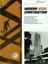
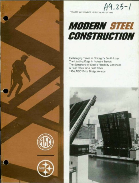
VOLUME XXV NUMBER 1 FIRST QUARTER 1985<br />
MODERN STEEL<br />
CONSTRUCTION<br />
Exchanging Times in Chicago's South Loop<br />
The Leading Edge in Industry Trends<br />
The Symphony of <strong>Steel</strong>'s Flexibility Continues<br />
A Fast Track for a Fast Track<br />
1984 AISC Prize Bridge Awards
One Financial Place:<br />
. Exchanging Times in the South Loop<br />
_<br />
•<br />
by Raymond S. Clark and John Zils<br />
Recent developments In Chlcagos<br />
south Loop are rapidly transforming<br />
what was once one of the cltys maJor rail<br />
transportation centers of the past Into an<br />
extension of the LaSalle Street financial<br />
district. an Exchange Center of the future<br />
Since t902. the LaSalle Street Railroad<br />
Station served as the primary metropolitan<br />
terminal handling passengers. mall and<br />
railway express for the Chicago. Rock Is·<br />
land and PaCIfic and New York Central<br />
Railroads The 13·story stalion house. al<br />
Van Buren Street between LaSalle and<br />
Sherman Streets served as the northern·<br />
most elemenl In a series of railroad facll·<br />
,t,es. elevated track structures and bag·<br />
gage and freight handling bUildings<br />
stretching several blocks to the south. The<br />
declining rail passenger traffiC of Ihe<br />
aymand S Clark IS an associate and prOject<br />
engineer With Skidmore. OWings and Merrrll<br />
Chicago UlinolS<br />
John lds ,s an aSSOCiate partner and senior<br />
SirUClura! engineer With Skidmore Owings<br />
and Mcrn In Ch cago 11111')015<br />
1950's and the later relocalion of a con<br />
sol,dated Amtrak passenger service to<br />
Chicago's Union Station eliminated the<br />
need for a malor rail terminal at LaSalle<br />
Street Station As time and the forces of<br />
nature took thelf toll on the faCilities. rail·<br />
road offiCials deCided to abandon the<br />
bUilding Planning began for a new<br />
smaller passenger terminal. to be located<br />
south of the Original terminal The new ter<br />
mlnal. Intended to accommodate the com·<br />
puter rail traffiC serving the southwest sub·<br />
urbs. was to be operated by the Regional<br />
Transportation Aulhorlty (RTA) The Orlgl'<br />
nal stallon and baggage handling faCilities<br />
from Van Buren Street to Congress Park·<br />
way were raled In t979 and the site was<br />
cleared and prepared lor new construclion<br />
New Development<br />
The flfst proJect to be developed In thiS<br />
Loop area was the addition 10 Ihe Chicago<br />
Board of Trade BUilding (CBOT) ThiS t983<br />
AISC Award-Winning faCility IS located<br />
north of Van Buren Street (see Fig 1) In<br />
t980 construction began on the new Chi.<br />
cago Board Options Exchange (CBOE) a<br />
$50-mllhon trading and office faCility Located<br />
on the slle of Ihe Original LaSalle<br />
Sireel Sialion. Ihe nlne,slory bUilding has<br />
ArtiSt's rendeflng of prO/eel/rom southwest<br />
showmg Board of Trade and add/tIOn.<br />
Chicago Board of OptIons Exchange and One<br />
Fmanclal Place
IIghlwelghl concrele lOpping slab Heavier<br />
conventionally reinforced slabs were reqUIred<br />
for Ihe lobby and public spaces<br />
as well as some MSE floors SpecIfic MSE<br />
floor loading cfltefla called for capacities<br />
ranging from the bUilding standard 50 psf<br />
+ 20 psf part II Ions to 225 psf for special<br />
computer power support facllilies All MSE<br />
equlfements were extensively researched<br />
and carefully documented Pflor to final<br />
framing deSign In some areas. the slab<br />
thickness was Increased to 3·ln deck plus<br />
3 '/ I-In concrete, uSing normal weight concrete<br />
to provide for VI bra lion damping As<br />
part of the architectural artlculallon of Ihe<br />
exteflor granite facade system. bay win·<br />
dows were provided at each tYPical and<br />
each corner column bay The facade system<br />
IS supported by cantilevered floor<br />
slabs at each level (Fig 3)<br />
Railroad Bridge Structure<br />
The LaSalle Street Station mallroom railway<br />
express offices and baggage handling<br />
faCilities oflglnally extended from the<br />
station house southward to Harrison<br />
Street These facllliles were located dlreclly<br />
below the raltroad trackbed framing<br />
ThiS framing bUitt ,n 1902 consisted of<br />
heavy flvetod plate·glfder construction<br />
supported on columns spaced approxlmalety<br />
15 II a c north'south and 12 II 0 c<br />
east west In 1939 the Chicago Department<br />
of Pubtlc Works began plans for a<br />
secllon of the Congress Street Expressway<br />
(later redeSignated Eisenhower Ex<br />
pressway) wlllch would extend from Wetls<br />
Street to Clark Street Since the eight-lane<br />
diVided highway was to pass through the<br />
eXisting faCilities and beneath the railroad<br />
trackbed framing It was necessary to replace<br />
the t 902 structure With a new column·<br />
free bfldge structure A condition 1m·<br />
posed by the railroad companies was that<br />
all train operations be allowed to continue<br />
B<br />
functlonlllg uninterrupted durlllg the<br />
phased bfldge construction<br />
DeSign of a two-span pier supported<br />
structural steel bfldge structure pro·<br />
ceeded dUfing the 1940s. The structure<br />
consists of 11 ,nd,v,dual track bed units<br />
and SIX passenger plallorm UllitS. each<br />
spannmg approXimalely 60 fl-2m. be·<br />
tween piers (see Fig 4) Each track unit IS<br />
made up of four W36 x 230 glfders tied<br />
together at 7 11-5 In Intervals by W18 flVeted<br />
diaphragms and a continuous +',-In<br />
thick x to-II Wide hOflzontal flange plate<br />
and concrete rail bed Each platform unll<br />
consists of two W36 x t 70 glfders tied al<br />
a Similar Interval by W t 6 diaphragms and<br />
a continuous h In flange plate and con·<br />
crete slab These units were preassembled<br />
off site and transported to the site by<br />
rail for the phased erection of the bfldge<br />
Foundation work for the bfldge structure<br />
actually began In t946 With the Installation<br />
of caissons for the south and center piers<br />
Subway construction was also proceeding<br />
al thiS time under the south four lanes of<br />
the expressway The north pier caissons<br />
were completed In 195t Continuous cals·<br />
son cap glfders were constructed and the<br />
reinforced concrete piers placed Final<br />
erection of the now track units and platforms<br />
was carefully sequenced so that no<br />
more than two of the It tracks were out of<br />
service at anyone time The bfldge construction<br />
was completed In 1956 and the<br />
expressway was opened becoming a ma·<br />
jor thoroughfare between the Loop and the<br />
western suburbs<br />
Planning lor the " Bridge Building"<br />
As the deSign team began the architectural<br />
programming of tile low-flse bUilding<br />
a flgorous englneeflng Investigation 01 the<br />
eXisting bfldge structure was Initiated The<br />
two activities proceeded concurrenlly. The<br />
results of the bfldge InveStlgallon even<br />
Fig. 4 Existing bndge frammg of track and platform umts. Note arrangement of low-nse<br />
columns to clear frammg, bear on piers.<br />
,<br />
• . II . TUCK """ ,<br />
tually dictated several of Ihe deSign pa·<br />
rameters Irom which the faCility was<br />
planned As previously menlloned the Iwo<br />
pflmary functions to be located In the low- •<br />
flse were the new RTA commuter station<br />
and the new Midwest Stock Exchange<br />
trading floor MS[ space requlfements<br />
also called for an observation gallery. employee<br />
cafetefla kitchen faCIlities and office<br />
areas Immediately ad lac en I to the<br />
trading floor Additional space planning<br />
was requlfed for functional amellitles to be<br />
prOVided by the owner These Include a<br />
restaurant. kllchen and dining faCilities.<br />
health club. sWimming pool . exerCise<br />
rooms and lounges Mechallical systems<br />
were requlfed which could properly service<br />
the trading floor environment. while<br />
meeting the needs of all adlolnlng spaces<br />
and functions The formidable task of<br />
blending all of the complex systems Into<br />
one ullique structure soon became apparent<br />
The evaluation of eXisting conditions of<br />
the bfldge took several phases The objective<br />
was to determine the SUitability of<br />
the bfldge as the foundation support for<br />
the new lowflse A related objective was<br />
to determine the supporting capacity of<br />
the bfldge In order to establish the maxImum<br />
posS! Ie sIZe and scope of the development<br />
ReView of the plot survey and<br />
Site topography enabled deSigners 10 be- •<br />
gin eSlabllshlng plan and elevallon rela<br />
Iionships belween the bfldge and Ihe proposed<br />
new lower ThiS was essential In the<br />
orgallizalional planlllng of bolh buildings<br />
Since all floors were Intended 10 be aligned<br />
for full Interlace<br />
Ttle Inillal phase 01 Visual examination<br />
of Ihe bfldge ,nvolved a review of IYPlcal<br />
Irack unll beaflng delalls on each concrete<br />
pair Column gflds were eSlabllshed<br />
based on Ihe layoul of Ihe lower al 15 II<br />
a c II was delermlned Ihal spacing Ihe<br />
low-flse columns al Ihls common gfld<br />
would mtroduce an array of diSSimilar<br />
beanng conditions Each column base<br />
would be unique and would reqUire elthe,<br />
partial removal of Ihe track unll framing or<br />
exlenslve delailing of sllffeners 10 receive<br />
the new columns It appeared more reasonable<br />
10 orgallize Ihe lowflse 9f1d so thai<br />
all columns are placed dlfeclly on the laps<br />
of Ihe concrete piers between Ihe Irack<br />
unit and platform framing (see Fig 4) ThiS<br />
slmpllflcallon allowed for Ihe slandardlZalion<br />
of column base delalls However Ihls<br />
approach did produce an Ifregular column<br />
spacing dlclaled by Ihe oflglnal layoul of •<br />
bfldge framing IdentlfYlllg Ih,s constralnl<br />
early dUfing deSign developmenl enabled<br />
Ihe archlteCIS 10 plan Ihe Inlerface of Ihe<br />
Iwo bUildings appropflalely<br />
A vlsuallnspecllon and lesllng program<br />
MODERN STEEL CONSTRUCTION
load and 60 psi supenmposed load Floor<br />
beams were designed for 125 psf live load<br />
and 60 psf supenmposed load and a<br />
30 000 Ib concentrated load al any point<br />
within Ihe span Live loads for Ihe other<br />
public spaces were IYP,cally 100 psf wllh<br />
up 10 30 psf allowed for Iloor finishes The<br />
very high loading cntena had a malar Impacl<br />
on floor beam deSign and final Ion<br />
nage As Ihe column gnd and floor Iramlng<br />
was finalized. column loads and locations<br />
were determined The evaluation of eXlsl<br />
Ing piers and caisson capacity verification<br />
was Ihen compleled<br />
Low-rise Structural System<br />
The pnmary space planning reqUiremenl<br />
lor the MSE Iradlng floor called for a tolally<br />
column-free space This could only be accomplished<br />
by beanng all columns directly<br />
on Ihe eXlsllng concrete piers.<br />
thereby resulting In a long-span structure<br />
The conceplual development of the SIXslory<br />
low-nse slructure led to Ihe deciSion<br />
10 Isolale the new construction from the<br />
eXisting track Unit platform umt framing<br />
10<br />
due 10 ItS Inability to carry Ihe concentrated<br />
column loads and lis Inherent flex<br />
Ibility The most logical framing system capable<br />
of meeting Ihe span cntenon while<br />
minimizing dead load was a long-span.<br />
two-bay Ilghtwelghl slruclural steel syslem<br />
The final deSign layout of Ihe low-nse<br />
SlruClure calls for a bUilding 121 x 208 It<br />
Bay spacing IS approxlmalely 18 It east<br />
west and Ihe long-span condition north<br />
soulh as previously noted with each span<br />
approxlmalely 60 It-l0 In The lower and<br />
low-nse have a slructural,nterface at each<br />
floor Levels 2 Ihrough 7 consisting of a<br />
propped cantilever braced diaphragm<br />
system (Figure 2) The syslem actually<br />
couples the Iwo bUildings together In the<br />
north·south dlfectlon This diaphragm pro<br />
Vides lateral slability for Ihe lowflse<br />
through Ihe linkage to the tower tubular<br />
frame and core braCing The fflcllonboiled<br />
conneclions were malnlalned only<br />
finger tlghl until the completion of the tower<br />
slructural sleel slabs and graOile cladding<br />
erection This allowed the linkage connec-<br />
Fig. 6. Mam roof trusses (above) were<br />
assembled on tradmg floor deck and<br />
erected by two cranes<br />
Fig. 7 TYPical field splice details (I., above)<br />
for main truss lOP and botrom chords<br />
Fig. 8. Mam truss top chord besflng (I.)<br />
simplified erection, allowed truss to be<br />
raised and placed on column cap<br />
plate.<br />
tlon to behave as a temporary hinge and<br />
enable Ihe tower to undergo Initial caisson<br />
seillements predicted to be 0 5 In 10 0 75<br />
In. The connecllons were recently torqued.<br />
up to complele Ihe laleral slability system.<br />
Lateral braCing of the lOW-rise In the east<br />
weSI dlfectlon IS provided by Iwo bays of<br />
vertical X-braCing at the north and south<br />
facade lines This braCing was deSigned<br />
10 procuce a displacement compatible<br />
with the lower laleral behaVior<br />
The long-span floor Iramlng employed<br />
Wide flange shapes ranging Irom W30 10<br />
W36. wllh all beams deSigned lor composlle<br />
action Floor slabs were either 3-ln<br />
composite melal deck and 3'/,-ln IIghlwelghl<br />
slab or a 61f.Hn reinforced con·<br />
crele slab on 3-ln. metal deck Certain<br />
areas of floor framing were suspended<br />
from long-span floors above In order to<br />
malnlaln Isolation of the superstructure<br />
from Ihe bndge framing These areas occur<br />
at Ihe sWimming pool and racquelball<br />
spaces<br />
The column-free 25.000 sq It trading<br />
floor IS made possible al Level 4 by span-<br />
MODERN STEEL CONSTRUCTION<br />
•<br />
•
Computer Capabilities In-House:<br />
• The Leading Edge in Industry Trends<br />
•<br />
by Leonard M. Rand<br />
Computer analysIs and design has be·<br />
come the focal point 01 a malor Industry<br />
trend Without repeating a long lisl of published<br />
market survey statistics. It IS suffiCient<br />
to say Ihal the NEJC Induslry IS In the middle<br />
01 a map' rush to computerize This move to<br />
aulomate Includes office producllVlty accounting<br />
proJOCt management CAD and<br />
computer-aided engineering (CAE) The<br />
reat reasons the AbC Industry IS plunging<br />
headlong Into the computer world are very<br />
simple pragmatic IUSllficatlons But the<br />
manner In which many f"ms approach this<br />
new Ironller IS anything but Slmpte and pragmalic<br />
This article locuses on the computerization<br />
opportunity and. through case<br />
studies. offers InSight and d"ectlon to firms<br />
that are Involved or soon Will be. In thiS often<br />
Intimidating process<br />
Pragmatic Reasons to Computerize<br />
All of the valid reasons lor a Ilrm to computeflze<br />
ItS operations bOil down to lust a few<br />
• RISing costs demand higher productiVity<br />
from every employee<br />
• The Industry demands more output In the<br />
same time period or the same output In a<br />
compressed time period<br />
• ExpenSive money and squeezed cash·<br />
flow demand rigid control 01 finances<br />
• More and more ct,ents expect their AlE<br />
E A. A E,C and consulting engineering<br />
firms to be current With the Industry<br />
trends on the leading edge<br />
• Much of today s Innovative architectural<br />
design reqUIres a computer for structural<br />
analYSIS and deSign An Increasing number<br />
of projects could not be undertaken<br />
Without a computer<br />
• Small service bUleau users are restricted<br />
In the fleXibility and cost effiCiency of the"<br />
computer capability<br />
Surveys Indicate that somewhere between<br />
50° .. and 75% of AE EA AEC and consulting<br />
engineering firms have some Inlernal<br />
operallons on a computer that the firm owns<br />
• Leonard M Rand. PE IS preSident and founder<br />
of The Rand Group Inc Dallas Texas a ma<br />
IOf U S developer of leading edge I.n.le ele·<br />
ment·based structural analYSIS and deSign<br />
sof!ware for the architectural 'engineering<br />
con ,truchon Industry<br />
151 Quarter 1985<br />
However. the surveys also clearly show that<br />
many of the firms who have computers In·<br />
house do not use them for structural analYSIS<br />
and deSign The overndlng reason for many<br />
firms' heSitation to Install CAE on an In-house<br />
computer system appears to be that englneenng<br />
management has great difficulty<br />
finding structural software to fulfill the" reqUirements<br />
Two Groups Rush to fnternalize CAE<br />
Even With the difficulty many f"ms face In<br />
Ilndlng and selecllng appropriate structural<br />
software the number of firms InternaliZing<br />
CAE grows at somewhere between 20%<br />
and 40% a year Two majOr factions of Ihe<br />
A ElC Industry compnse the rush to Inhouse<br />
CAE. Each group has ItS own unique<br />
set of problems and needs Each approaches<br />
the search and purchase of CAE<br />
hardware and soltware differently<br />
The I"st group IS made up of Ilrms who<br />
have prevIous CAE expenence through external<br />
resources. such as service bureaus<br />
These firms are familiar With some form of<br />
mainframe-based structurat analYSIS (and<br />
sometimes deSign) software. These f"ms<br />
are. as a rule. well Informed on the CAE sublect<br />
and can evaluate obJeclively hardware<br />
and software options II supplied suffiCient<br />
oblectlve Information Their evaluation of an<br />
In-house system Will be placed In the Iramework<br />
of prevIous CAE expenence What<br />
these firms usualty seek IS a hardware-soft<br />
ware system that IS at least as versatile. sophisticated<br />
and powerful as the malnframebased<br />
resource they have been uSing They<br />
are purchasmg everything Irom PCs to<br />
super mlnl+computers<br />
The second group. however. lacks such<br />
CAE expenence They are the small firms<br />
who are taking their first ptunge Into CAE<br />
and are dOing so With the In-house approach<br />
These f"ms are baSically bUYing<br />
PCs and then looking for software to dnve<br />
thelf new computers Wilt' no performance<br />
benchmark to gUide them. they can eaSily<br />
overestimate what an InexpenSive piece of<br />
hardware and'or soltware can do lor them<br />
Because of budget I,mltattons. they sometimes<br />
allow themselves to think only In terms<br />
of today's needs vs tomorrows reqUirements<br />
These firms are sometimes tempted<br />
to spend heaVily on the hardware (relative to<br />
their budget constraints) and compensate<br />
by skimping on software Invanabty such a<br />
course results In dissatisfaction With the 5011ware<br />
that IS deemed Inadequate Within SIX<br />
months<br />
Mixed Approach to Software Solutions<br />
Depending on prior experience and Inhouse<br />
experllse. Ilrms InternaliZing CAE pproach<br />
their ultimate software sotuttons ,n J<br />
vanety of ways Some of the bigger firms<br />
write soltware programs for a portion of the"<br />
CAE needs However the majOflty of tile<br />
software they use IS purcl1ased Irom Uurd<br />
party developers The home grown software<br />
programs are olten the Simple structural uIII<br />
Ity programs used to tackle the Simple daVto-day<br />
tasks not the powerlul anatysls and<br />
design software needed for majOr prOlects<br />
These comprehenSive Integrated software<br />
systems reqUire several man years of sopl11stlcated<br />
development and progiammllig<br />
effort not leaslble lor these firms to under<br />
take<br />
The smaller firms With no ability to wtlle<br />
the" own programs buy the software they<br />
feel they can afford Based {)f1 current pur<br />
chase patterns milny 01 these Ilrms appear<br />
to be bUying small softwdre programs that<br />
are pieces of a total sotutlon Feeling that fj<br />
10lal In· house solullon IS un ffordablc they<br />
do what thell o;oftware p,cces atlow them to<br />
do In·house jfld use a remote service bureau<br />
lor the 1'''\Jer more complex prOlccts<br />
the" In-house yS\ern cannot harxlle Suet,<br />
a deciSion 11kJ f ilave been based 011 budget<br />
constraints or may have evolved becaust:<br />
the f"m coutet not find a comprel,enslve soft<br />
ware system which would serve all thell<br />
needs<br />
A UlItd group seeks to purchase a COrT"<br />
plete CAE solution that wllI,nternahze the en<br />
lire analySIS and deSign requirements With<br />
no need 101 servIce bureaus These t,nns<br />
look lor a system to Integrate a\l the" CAr<br />
needs Into a Single software system they Will<br />
not outgrow They want the system to be ml<br />
cro- or mini-computer based Ideally they<br />
woutd like software to serve the" needs Will,<br />
equat ease whether It was running on stand<br />
atone workstations or dnvlng a multi-terminal<br />
system Mo',t of the',e f"ms are stllttooklng<br />
Current Perceptions of CAE Software<br />
Alt 01 the purchases of CAE software to date<br />
have been based on the market s percep<br />
tlon of the structUiat software avaltabte at the<br />
lime Some perceptions are accurate Far<br />
15
too often however. purchase decIsions<br />
have been a consequence of misinformation<br />
and Inaccurate perception To compound<br />
the difficulty the marketplace IS a<br />
very dynamiC one What was qUite true tast<br />
year may be totally Inaccurate today For exampte.<br />
a prevatent perception IS that the<br />
power. versatility and sophistication of software<br />
IS directly related to the hardware on<br />
which It runs In other words. malnframebased<br />
software IS the most powertul, versatile<br />
and sophisticated software on the market<br />
MIni-computer software IS second and<br />
micro-based software IS the least of all Such<br />
a percepllon was true a year or two ago It<br />
IS certainly not true In all cases loday Yet.<br />
too many films make bUYing deCISions<br />
based on such Ideas<br />
Because of the perceived cost far too<br />
many small firms may also be selling themselves<br />
short by assuming the only option<br />
avaltable to a small budget IS to buy a piece<br />
of the total solution now and start all over<br />
with a new software (and maybe hardware)<br />
solution laler on when more money IS available<br />
New advances In micro computerbased<br />
software systems have already elim<br />
Inated the need for most firms to think In<br />
terms of such planned obsolescence.<br />
Several artlcies In magazines. newspapers<br />
and journals throughout the NEJC Industry<br />
have spotlighted another problem Inherent<br />
10 Ihe Internalized CAE trend Too<br />
many less Informed engineers with little or<br />
no prevIous CAE expenence are purchaSing<br />
Fig. 1. St. FranCIS Hospital. Photo shows<br />
girder layout for hexagon-shaped 11-story<br />
moment·reslstmg frame.<br />
--- _-<br />
16<br />
Inadequale analysIs software and aUempt<br />
Ing to use It for structural projeCts outSide the<br />
abilities of their In-house software. Fortunately<br />
most of these engineers soor diScover<br />
Ihe InadequaCies of their solullon. and<br />
correcl the problem ThiS realization often<br />
reqUires a firm to scrap the software already<br />
purchased and seek oul an appropnate<br />
software tool which Will do what they need It<br />
to do ThiS process. With liS Inherenl false<br />
start, IS usually a consequence of bad perception<br />
and Inadequate knowledge of the<br />
CAE software marketplace<br />
Learning from the Past<br />
Those firms currently In the process of InlernallZIng<br />
CAE do so because they see It<br />
as a step necessary to survival and prospenty<br />
They are correct In their assessment<br />
of the situation The trouble IS most firms<br />
do not have the luxury of time on their Side<br />
The demands of Ihe marketplace no<br />
longer allow firms 10 take to years to find<br />
a sUitable In-house solullon. The process<br />
can be lackled rather qUickly All that has<br />
10 be done IS 10 learn from firms who have<br />
already gone through the process and<br />
have found excetlent solutions for In-house<br />
CAE requirements The follOWing Ihree<br />
case studies will answer many quesllons<br />
and give excellent direction to Ilrms of all<br />
sizes who are currently In the midst of the<br />
march toward In-house CAE systems<br />
HTB, Inc., Oklahoma City, Oklahoma<br />
HTB. Inc. IS an archllecturalenglneenng<br />
firm With offices In Oklahoma City and<br />
Tulsa Okla Washington, 0 C., and San<br />
Jose Cal Their structural englneenng de·<br />
partment at the Oklahoma City headquarters<br />
serves the enllre corporate network.<br />
The first lime HTB used a computer to<br />
analyze a structure was In t 964 One of<br />
their prOjects had a V,erendeel truss which<br />
supported both the roof and the ftoor<br />
across a 54 oft span They had to travel 25<br />
miles to use a univerSity computer where<br />
the data was keypunched onto cards<br />
proofed and fed Into the computer After<br />
the data was analyzed HTB slill felt the<br />
need to venfy the results by hand calculations<br />
In t 966. deSigns for continuous-span<br />
bndge girders were done for HTB by De<br />
Leuw Cather Company HTB engineers<br />
would complete coding forms and mall<br />
them to Chicago. where the computer was<br />
located In those days air mall often took<br />
two days By 1968. HTB was deSigning<br />
mosl of their structures on a computer<br />
owned by a local college They furnished<br />
the serVice person a completed code form<br />
at 500 pm. each evening He spent the<br />
night keypunching and de-bugging so he<br />
could provide the necessary output by<br />
800 a m. the next morning<br />
As their volume of computer·supported<br />
deSign work grew the overnight system •<br />
became unsatisfactory Time constraints<br />
and limited software availability forced<br />
HTB to make a change In t 975. they<br />
turned to the McDonnell Douglas com·<br />
puter center In St LOUIS, Mo One of the<br />
first prolects they deSigned With the<br />
McDonnell Douglas computer was the t 1·<br />
story west wing for St FranCIS Hosp'tat In<br />
Tulsa , Okla (Fig t) ThiS hexagonalshaped<br />
steel. ngld-frame bUilding was<br />
analyzed uSing a three-dimenSional model<br />
and the McAuto version of STRUDL software<br />
Since HTB had no In·house terminal<br />
to access the computer. their project manager<br />
flew to St LoUIS and ran the program<br />
With the assistance of a McAuto analyst<br />
With the 3-D analYSIS. HTB was able to<br />
reline member sizes until a very effiCient<br />
steel frame that would take Wind loads<br />
from all dlrecllons was deSigned<br />
HTB linked Itself to a nationWide network<br />
of computers on a tlme-shanng baSIS In<br />
t976 Their In-house terminal was linked<br />
to the Kansas City computer center to ac·<br />
cess state· of· the-art software via telephone<br />
modem They had some programs<br />
written Internally, which were also available<br />
on the computer A pnme example of •<br />
prOjects handled With thiS service bureau<br />
program IS the 37 -story steel-framed Mld<br />
Conllnent Tower deSigned In t98t (Fig 2)<br />
HTB used the SPACE IV structural analYSIS<br />
and deSign program The extensive tlmeshanng<br />
charges Incurred With thiS prOject<br />
prompted HTB to Invest In their own computer<br />
capability The software they selected<br />
allowed them to do much of thelf<br />
deSign work on the mini computer based<br />
system they purchased However HTB<br />
discovered they were severely limited by<br />
the number of members the software could<br />
handle at one time Scftware also lacked<br />
3-D capabilities and code checking<br />
In t 984 HTB purchased proprietary<br />
structural analYSIS and deSign software<br />
which takes care of all their stallc and dy·<br />
namlc analYSIS . accommodallng both 2-D<br />
and 3-D analYSIS and deSign. Keith Hinchey<br />
P E senior vice president and director<br />
of structural englneenng finds thiS<br />
speCial program solves the problems of<br />
their prevIous software and adds many<br />
versatile features they did not expect<br />
"One of the systems features we find most<br />
helpful IS the one which enables us to exhlbilihe<br />
slruclUre on our graphiCS terminal .<br />
while the engineer works the analYSIS on<br />
another terminal · explains Hlnchey'Coupie<br />
thiS aUnbute With the editing capabll·<br />
Itles and the systems advantages multiply<br />
Our prevIous software reqUifed us to<br />
MODERN STEEL CONSTRUCTION
change the entire t'St of member properties<br />
fustto change a slngte member prop<br />
•<br />
erty '<br />
Hinchey summarizes HTB's CAE experience<br />
that has spanned two decades<br />
"Engineering software has Improved<br />
steadlty Since we first designed our Vierendeettruss<br />
In 1964 Now offices with onty<br />
a few clients can afford a computer which<br />
can sotve multi-member frames This IS<br />
onty possible tocay because software developers<br />
understand how the computer<br />
thinks and how to use the computer to ItS<br />
utmost capacity They also understand engineers<br />
and engineering and produce<br />
software that solves the problems rather<br />
than contributing to the problem"<br />
Biar & Frost, Inc., Dallas, Texas<br />
Blar & Frost . tnc IS a small. five-person<br />
structural engmeerlng firm. Their use of<br />
CAE spans 11 years In the early years,<br />
most projects were handled uSing traditional<br />
hand calculation methods, reserving<br />
the big projects for the expensive timesharing<br />
met hoc Between 30% and 50%<br />
of their prolects required some computer<br />
analysIs via service bureaus<br />
Jack Frost. one of the firms partners,<br />
characterizes their search for Internal CAE<br />
capability In terms of commitment level<br />
'We poked around looking at computers<br />
•<br />
and soltware out of sheer CUriosity for<br />
about 10 years ' Frost explains "We<br />
looked with genuine Interest for about five<br />
years Finally. we spent about three years<br />
dOing hard looking with real Intent to buy<br />
What we were looking for was something<br />
at least as 9000 as STRUDL. which we<br />
used through the service bureaus"<br />
In 1981 his firm Invested In a medium<br />
capacity 2-D frame program that Significantly<br />
reduced their dependence on the<br />
service bureau According to Frost. We<br />
knew It was a temporary measure But we<br />
saw It as step one toward our own In-house<br />
capability" Limited member handling capacity<br />
and the lack of 3-D capability<br />
helped contribute to their decIsion to purchase<br />
a full analySIS and design system In<br />
less than one year<br />
Blar & Frost s story IS a familiar one A<br />
specIfic project and Its related problems<br />
determined the liming for gOing totally In·<br />
house With their CAE In early 1983. they<br />
began preliminary deSign work on the Sid<br />
W Richardson PaVilion a multi-story ad<br />
•<br />
dition to Hams Methodist Hospital In Fort<br />
Worth Tex (see Fig 3) Page Southerland<br />
Page a Fort Worth architectural firm. had<br />
deSigned an eight-story structure that<br />
would grow to 20 stories as the need demands<br />
The deSign posed several englneeflng<br />
challenges that forced Blar & Frost<br />
to go to STRUDL on the service bureau<br />
1 st Quarter 1985<br />
computer The engineering challenges mcluded<br />
a slender. asymmetrical patient<br />
lower With a two-bay frame at one end, a<br />
full-height cantilevered. semicircular stair<br />
tower With torSionally loaded spandrels<br />
all as an external appendage to the tower<br />
and a double-cantilevered connecting<br />
passageway between the eXlsling structure<br />
and the new annex which took the<br />
form of a 47-ft long box truss passing from<br />
the third and fourth ftoors of the eXisting<br />
bUilding to the second floor of the new<br />
annex. The use of ramps Installed Within<br />
the box truss made the multi-floor access<br />
possible (Fig 4)<br />
Midway In analYSIS and deSign on the<br />
service bureau system. the service bureau<br />
enacted a poliCY change that sharply cur<br />
tailed support for small accounts In the<br />
Dallas area The support person B,ar &<br />
Frost had deall With was terminated and<br />
the position permanently vacated Log-on<br />
procedures were changed Without not,f"<br />
calion and nobody was able to use the<br />
system Nearly a week of telephone calls<br />
to the home office did not resolve the access<br />
problem The need tor computer time<br />
was becoming Crllical At that pOint. rela<br />
lions With the remole service bureau were<br />
terminated "1m sure the big users get ex<br />
cellent service." confided Frost "Like so<br />
many others we were just too small to be<br />
handled economically by the serVice bu <br />
reau staff Our $15000 to $20.000 In annual<br />
fees Just was not significant to them ·<br />
Simultaneous to cessation of relations<br />
With the service bureau. B,ar & Frost became<br />
aware of RAND-MICAS. a flntte etement-based<br />
structural analYSIS and design<br />
software system. After only three days<br />
evaluation. they purchased the software<br />
system and a mini-computer to run It As<br />
Frost put It. "We finally found something<br />
much better than STRUDL we could use<br />
In-house"<br />
With the new mml computer-based system<br />
Installed. the tlrm was able to continue<br />
ItS work on the Hams Hospital prolect Although<br />
the eXisting bUilding was a reinforced<br />
concrete frame With brick veneer<br />
It was not assumed concrete was appro·<br />
prlate for the new annex Both steel and<br />
reinforced concrete were closely exam<br />
Ined With the new system'S deSign postprocessors<br />
before determining that a<br />
welded. moment-resisting steel frame was<br />
the best chOice for thiS project<br />
In the year and a hall Since they acqUired<br />
their current computer and soft <br />
ware system. many things have changed<br />
Frost describes their currenf system as a<br />
"quantum leap ahead of the time-sharing<br />
arrangement Frost says It IS not necessarily<br />
a mailer of dOing more work. but of<br />
dOing the work beller and stili meellng<br />
tough lime schedules Originally expensive<br />
time-sharing costs forced them to<br />
think In terms of Single-run analYSIS 'Now<br />
we never do anything just one way ' explains<br />
Frosl ·We play With II We examine<br />
II from many pOints of view'<br />
It IS now Ihelr standard procedure that<br />
after a project IS analyzed the deSign IS<br />
always looked at from bolh a SlruClural<br />
steel and a reinforced concrete point of<br />
view One partner takes steel while the<br />
other takes concrete On the next prOlect.<br />
they reverse Ihe roles After deSign work<br />
IS compleled by both. an Inlernal crltlqlle<br />
session lakes place From Ihe cflilque and<br />
often after a lively exchange of opinions<br />
the firm has a well-documented point of<br />
view to present to a chent<br />
Their In-house CAE software toot has<br />
done something else 10 the way they do<br />
things As Frost put It 'We have alSo be<br />
come a very valuable source of Information<br />
for the architect which we could never<br />
have been before Ins lead of JUSI a pro/)<br />
lem-solver for the architect we are are·<br />
Fig 2. Mid Contment Tower. HTB used<br />
SPACE IV structure analYSIS on 37-story<br />
steel framed·tower.<br />
17
source. We now provide more creative en·<br />
glneerlng solullons Ihan we ever could<br />
wllh Ihe IImllallons of lime-sharing" He<br />
cites a recent project where the architect<br />
with whom they worked asked a question<br />
Frost had never considered before "Can<br />
we build an asymmetrical Vlerendeel<br />
truss?" Frost's reply was, "I don't know<br />
Let s lind out" Both had their answer In a<br />
matter of minutes It was a definite yes l<br />
The architect was able to continue his design<br />
with Invaluable knowledge readily<br />
available from his consulting IIrm<br />
Frost characterizes his current CAE software<br />
capabilities as "a system that really<br />
works He explains "It IS a current. practical<br />
tool that lust happens to be state-ofthe·art<br />
technology It's a system with which<br />
we can grow We see It as a total CAE<br />
solullon for us now and for many years to<br />
come Every firm seeking to have an Inhouse<br />
CAE program should expect noth<br />
Ing less from any system they are conSidering<br />
DeSimone, Chapfin and AssOCiates,<br />
New York City<br />
DeSimone, Chaplin and Associates Consulting<br />
Engineers PC IS a medium-sized<br />
consulting hrm of 20 employees With 01flces<br />
In Manhattan DC&A has used a mini<br />
computer· based CAE system Since 1981<br />
The Humana Corporation headquarters<br />
bUilding was an excellent opportUnity to<br />
put the software through ItS paces<br />
As Fig 5 Illustrates the Humana Cor<br />
oratlon headquarters bUilding In LoUls-<br />
tS<br />
Ville, Ky IS not a simple rectangular box<br />
high-rise bUilding The faint architectural<br />
prolect of GravesiWarnecke produced a<br />
structurally complex bUilding wllh SIX dlflerent<br />
wlnd-reslsllng moment frames In the<br />
north-south direction and lour In the eastwest<br />
A tYPical symmetrical rectangular<br />
bUilding normally reqUires the design of<br />
two exlerlor frames The architectural design<br />
of the two-lour story lobby and ground<br />
floor loggia as well as the dllferlng setbacks<br />
from the 20th floor to the roof elim<br />
Inates any structural symmetry Of the SIX<br />
nort h-south Wind frames, only two are<br />
Identical None of the east-wesl frames are<br />
Idenllcal ThiS meant that nine separate<br />
Irames needed to be designed<br />
The bUilding also has other major archltecturalleatures<br />
such as the flying truss<br />
supporting the 24th-story balcony which<br />
Interacts With the basIc structure of It The<br />
three-dimenSional effects of thiS and several<br />
other features had to be evaluated In<br />
coni unction With the Simpler acllon 01 the<br />
Wind Irames All these features Imposed<br />
many engineering challenges over and<br />
above those typical of a normal high-rise<br />
bUilding<br />
Before any serious engineering deSign<br />
could commence DC&A needed to determine<br />
the structural system and material<br />
best SUited for the profect. Their evaluallon<br />
qUickly centered on reinforced concrete<br />
and structural steel The architectural design<br />
reqUired spans of up to 40 It, With 9<br />
It clear for the floor-to-flnlshed-ceiling ThiS<br />
combination of long spans and tall storyto-story<br />
heights meant that control of the<br />
bUilding movement due to Wind would be<br />
Figs. 3 & 4. Architectural model of Harris<br />
Hospital Method/st, With new Richardson<br />
PaVIlion In leh foreground. TYPical Plot (I.)<br />
shows analytical model of cantJIevered box<br />
truss passageway between old and new. Plot<br />
/s used as venf/catlon and documentation<br />
tool.<br />
more difficult than In a normal bUilding<br />
Preliminary work Indicated reinforced concrete<br />
member Sizes would be much larger<br />
than structural steel •<br />
The bUilding SitS on a mat found allan<br />
and the extra weight of a concrete structure<br />
also posed serious complications to<br />
the foundation deSign as well A third malar<br />
conSideration was the fleXibility of a<br />
structural steel Irame to accommodate<br />
modilications for mechanical openings<br />
and beam penetrations alter Ihe structure<br />
IS erecled ThiS third conSideration IS not<br />
unusual, Since construction of the Humana<br />
BUilding was 10 begin prior to final architectural<br />
and mechanical deSign, requiring<br />
a certain number of holes to be accom·<br />
modated later on All three conSiderations<br />
clearly pOinted to structural steel as the<br />
best solution<br />
With preliminaries completed, DC&A<br />
began Ihe detailed structural deSign Mike<br />
TheiSS. an associate. VOiced the common<br />
conflict that continually challenges the<br />
consuiling engineer In thiS phase of a proJect<br />
"It IS the nature of the structural deSign<br />
prolesslon that some architectural concepts<br />
reqUIre greater effort on the part of<br />
the engineers than others," TheiSS exptalns<br />
"It IS also the nature of our protessian<br />
Ihat owners do not Willingly pay a<br />
compensatlngly greater fee to the eng 1- •<br />
neer when thiS occurs Therefore, qUite<br />
often, engineers are faced With making the<br />
chOice between dOing more work than the<br />
fee can cover or making conservative as·<br />
sumpllons which reduce the engineers'<br />
workload but IneVitably add unnecessary<br />
material and cost to the prolecl "<br />
TheiSS hnds relief lor thiS no-win situation<br />
through hiS In-house CAE system As<br />
he puts It. "The engineer's best Irlend In<br />
hiS quest to balance the work vs lee problem<br />
IS the In-house computer and a properly<br />
Inlegrated syslem of software programs<br />
for analYSIS and deSign For the<br />
one-time expenditure eqUivalent to a typ<br />
Ical engineers salary It IS finally pOSSible<br />
to own a system that can perform a comprehenSive<br />
analYSIS and aid In the deSign<br />
and checking of very large structures<br />
DC&A now uses a hnlte element-based<br />
structural analYSIS and deSign system bUilt<br />
around a relational database<br />
TheiSS warns the engineering firm In·<br />
vestlgallng CAE systems to know wha t to<br />
look lor He pOints out that not all analYSIS<br />
and deSign soltware IS Integrated "True<br />
•<br />
Inlegrallon IS the ability 10 go Irom analYSIS<br />
to deSign Without haVing to manually enter<br />
results Irom the analytical phase or to be<br />
able to have member Sizes adfusted from<br />
the calculations of the deSign program to<br />
reanalyze a given problem" TheiSS warns,<br />
"Most structural software packages for<br />
MODERN STEEL CONSTRUCTION
Fig 5. Humana Corp. headquarters.<br />
Structurally complex bUlldmg reqUIred<br />
. deslgn of mne separate frames<br />
•<br />
analysIs and design are not fully Integrated<br />
and therefore waste valuable engineering<br />
lime<br />
TheiSS uses the Humana bUilding as a<br />
perfect example of uSing Ihe right software<br />
system to solve a most dlfhcult problem<br />
He explains the unusual structural nature<br />
of the Humana prOlect would have posed<br />
a serious problem to DC&A had Ihey not<br />
had the proper In-house CAE capability<br />
Because of the number of separate frames<br />
and the complicated detailing on the upper<br />
stones. numerous tnal runs were reqUlfed<br />
to converge on an economical<br />
structural solution As he explains. "The<br />
cost of uSing an outside service bureau<br />
would have posed a very real restraint on<br />
the number of tnal solullons we could have<br />
Invesllgated •<br />
TheiSS expanded on DC&As expenences,<br />
contrasting service bureaus with<br />
In-house capabilities ·Our pnor expenence<br />
with service bureaus proves that ac<br />
cess tor the smaller user IS not always<br />
speedY Most eng meers are minimum<br />
users compared to the large corporate<br />
users Many of us try to use these expensive<br />
systems at night when the rates are<br />
lower It becomes difficult to do more than<br />
one run a day Wllh our In-house system.<br />
1 st Duarter 1985<br />
we make many runs a day If necessary<br />
With a multi-user mini computer system<br />
like ours. the englneenng Ilfm can also run<br />
more than one problem at the same lime<br />
ThiS capability has significantly Increased<br />
DC&As ability to produce high quality englneenng<br />
solullons qUickly and effiCiently<br />
DeSimone. Chaplin and ASSOCiates expenence<br />
with In-house CAE has been a<br />
very successful one TheiSS says thelf system<br />
has actually enhanced thelf ability to<br />
handle specialized. non-standard bUilding<br />
structures -like the Humana BUilding 'We<br />
can handle these non-standard structures<br />
without penalizing the owner with an overly<br />
conservative deSign. while not penalizing<br />
DC&A by exceeding the lee. he conhdes<br />
'Our computer system allows us to satisfy<br />
the owner's needs. the architect s deSign<br />
and our fee sChedule and we can do It<br />
qUlckty'<br />
Those Who Have Done it OHer Advice<br />
Hinchey. Frost and TheiSS all offer sound<br />
adVice to firms of any size who are Investigating<br />
an Internal CAE capability Many<br />
01 the hints listed below were vOlc3d by all<br />
three men All agree the process can be<br />
an Intimidating one but does not have to<br />
be Here IS a summary 01 Ihelf adVice<br />
Seven Tips to Top Capability<br />
1. Understand Why You are DOing II Keep<br />
your true oblectlves clearly In mind You<br />
want 10 solve as many problems and<br />
provide as many necessary tools as you<br />
can Do nOI allow yourself to be blind<br />
Sided by a machines whlslles and<br />
bells and forgel that a computer does<br />
nol do anylhlng until It has software 10<br />
drive It<br />
2_ Start with Software Then Find Besl<br />
Compuler The most popular com pule!<br />
With all kinds of machine capabilities<br />
cannot compensate lor Inadequate<br />
software The besl software on the mar·<br />
ket does nOI usually need a specIfic<br />
hardware lea lure lound on onty one<br />
system to do ItS best lor Ihe engineer<br />
3_ For Micros and Some MIniS. be Prepared<br />
to Spend as Much or More for<br />
Software as for Hardware Do not expect<br />
to spend a few Ihousand dollars<br />
for the machine and a lew hundred 10/<br />
the software a sure route to shortchanging<br />
yourself<br />
4. Plan for Fulure Needs Oon'l Slap al<br />
SolVing Today's Needs Many engineers<br />
are under Ihe ,mp,esslon Ihal everyone<br />
who has a modest budgel musl buy a<br />
parllal solullon system In the beginning<br />
Ihen Ihrow II oul later when needs demand<br />
and budgels permit ThiS IS not<br />
necessarily so It IS possible 10 find a<br />
complete solution which can be viewed<br />
as enlry level Siudy the available oplions<br />
before locking Into planned obsolescence<br />
5. Investigate Thoroughly, but Oont Make<br />
II a Career It IS mosl Imp0r/anllo make<br />
a Ihorough sludy 01 al leasl live of Ihe<br />
besl opllons available before chOOSing<br />
software and hardware Too many engineers<br />
lake years to do whal a few<br />
monlhs sludy woutd accomplish beller<br />
Sel a Ilmelabte and work hard 10 Slick<br />
to It Better deCISions are made by<br />
weighing opllons fresh In memory<br />
6_ BUYlflg a CAE System IS Like Mamage<br />
II IS a Famlty Allalf Even Ihe beSI<br />
soltware around Will not serve well If II<br />
does nOI have excellenl sUPPOr/ from<br />
Ihe company who developed It ThiS<br />
supporl should Inc tude a slrong com·<br />
mllment to ongoing soltware reflnemenl<br />
and developmenl 1/ shoutd atso Inctude<br />
providing enhancemenls and new re <br />
leases providing comprehenSive<br />
hands-on training for staff providing<br />
hOI-line access 10 protesslonal engl.<br />
neers who act as first-line lechnlcal suppor/<br />
for your quesllons and probtems<br />
Expect to pay lor such sUPPOr! alleasl<br />
t 0% 01 Ihe software purchase cosl annually<br />
If a vendor olfers free or very<br />
cheap suppml. It Will be worth every<br />
penny of II<br />
7. Know What tile Software System Ought<br />
10 Have Then Ask POlnled Ouesllons<br />
on Just Whal Thel( Syslems Olfer Hinchey<br />
Frosl and TheiSS agree you can<br />
have the besl syslem bul only If you<br />
know whal Ihe besl syslem aug hi 10 be<br />
able to do They point oul the besl Slruclurat<br />
anatysls and deSign syslem oughl<br />
10 have all Ihese leatures as minimum<br />
requirements<br />
• Be available on a vaflely 01 computers<br />
Ideally on bOlh micros and<br />
miniS The miCro verSion needs to be<br />
lunCllonally Idenllcal 10 the mini ver<br />
Sion<br />
• Do bOlh Ira me- and Ilnlte-etemenl<br />
analYSIS<br />
• Provide both 2-D and 3-D analYSIS and<br />
deSign<br />
• Perlorm bolh SialiC and dynamiC anal·<br />
YSls<br />
• Be bUilt around a true relational database<br />
so Ihe syslem IS Inlegraled and<br />
highly fleXible. allOWing Ihe engineer<br />
to flow from analYSIS to deSign and<br />
back again al Will<br />
• Provide a variety 01 analySIS postprocessors<br />
to expedite the analYSIS proc·<br />
ess<br />
• Provide resldenl code checking lor<br />
bolh steel and concrete deSign<br />
• Be ab'e 10 handle VIrtually any size<br />
structure With ease I<br />
19
of expansion bolls between face plates<br />
and the eXisting concrete structure was<br />
devised As with the design of the strucetural<br />
steel elements. careful analysIs determined<br />
the level 01 shear and tenSion In<br />
each boll The size and required embedment<br />
length of each boll IS specilled accordingly<br />
With discrete connection pOints at each<br />
eXlsllng exterior column, minimal demolition<br />
work IS reqUIted at the eXlstmg exterior<br />
wall The erection sequence calls for all<br />
the column collars to be Installed prior to<br />
erection of trussed brackets and lloor<br />
beams There IS mlnlmat disruption to the<br />
eXisting structure With thiS concept, Since<br />
all of the major steel elements are externally<br />
applied to the bUilding After the<br />
structural steel was Installed and the new<br />
space In place. the old exterior wall was<br />
removed and the deSired enlargement of<br />
the eXisting lloor space created<br />
As previously mentioned, one of the<br />
chief advantages of the trussed scheme<br />
over the roof cantilever scheme IS that the<br />
load transfer path IS more direct New lloor<br />
and roof loads are channeled Into the ex<br />
Isting columns at their correspendlng levels<br />
(or lower) so that the eXisting columns<br />
resist decreaSing loads as they ascend.<br />
Each column and fOOling In the eXisting<br />
structure affected by the new construction<br />
has adequate reserve strength to safely<br />
suppert Ihe new loads Siruciural steel<br />
construction was the only solution-Since<br />
light weight, durablhty, erectablhty and<br />
economy were essenllals for thiS project<br />
Conclusion<br />
The Stoneman BUilding Includes medlcall<br />
surgical and obstetrlcat nursing umts, diagnostic<br />
cardiology, clinical neurophYSIology<br />
and dialYSIS Total cost lor these renovations<br />
and new construction IS<br />
$13,635,000 Bedrooms deSigned to resembte<br />
the new ones In the Reisman Build<br />
Ing Will be generated by Stoneman's lateral<br />
expansion The lateral expansion<br />
becomes the locus for the new pallent tOIlet<br />
rooms, a loungel sllllng area for VIsitors<br />
and a generous expansive Window open<br />
Ing affording a view over Boston's Fenway<br />
Park. Pallents In each room Will lace oakpanelled<br />
walls With Integrated ward robes,<br />
balanced by strongly organized color sclutlons<br />
lor repese The room IS deSigned<br />
to increase the patient's feeling of wellbeing<br />
at Boston's Beth Israel Hospital<br />
the first hospital to create a Patient Bill of<br />
Rights.<br />
As a result 01 the combined new addition<br />
and total renovallon, Ihe Stoneman pallent<br />
care uOlis are brought up to the standards<br />
of Ihe new Reisman BUilding, and Will pro<br />
Vide patlenls Ihe same Inllmale quality and<br />
Intenor enVIronment The solution also extends<br />
the life span of the eXisting bUilding<br />
Into one equal to that of the bUlldmg recently<br />
constructed The architect and<br />
structural engineering team have once<br />
again shOwn Ihat structural steel construction<br />
prOVided the best pesslble solution to<br />
a complicated expanSion problem al a<br />
large medical center 0<br />
Architect<br />
Martha L Rothman-Elliot Paul Rothman Inc<br />
BoSlon. Massachusetts<br />
Structural Engineer<br />
Souza, True and Partners<br />
Watertown , Massachusetts<br />
<strong>Construction</strong> Manager<br />
Jackson <strong>Construction</strong> Company<br />
Dedham. Massachusetts<br />
Steet Erector<br />
Daniel Marr & Son Company<br />
Boston. Massachusetts<br />
Owner<br />
Bem Israel Hospnat<br />
Boston. Massachusetts<br />
STRUCTURAL ENGINEERS:<br />
TAKE US FOR A TEST RUN<br />
Structural AnalySIS Inc" has now completely eliminated "hope & pray" bUYing of computer software. Through the use<br />
of a speCial diskette -we can now offer a limited number of runs of our actual programs (not demo disks) for your<br />
complete evaluation at a low nominal fee ,<br />
,< <strong>Steel</strong> Frame Analysis & DeSign<br />
,< <strong>Steel</strong> Beam AnalYSIS & DeSign<br />
,:- <strong>Steel</strong> Cotumn AnalYSIS & Design<br />
-:< Frame Shearwall Interaction Analysis<br />
{< Complex <strong>Steel</strong> Plane Frame AnalYSIS<br />
-::- Extended <strong>Steel</strong> Column DeSign<br />
Please write for more information and product<br />
literature,<br />
I I<br />
1st Ouanar 1985<br />
STRUCTURAL<br />
ANAL VSIS, INC.<br />
{< <strong>Steel</strong> Pipe Column AnalYSIS & DeSign<br />
-:< <strong>Steel</strong> Tube Column AnalYSIS & DeSign<br />
-:< Composite 8eam Anatysls & DeSign<br />
{< <strong>Steel</strong> Truss AnalYSIS & DeSign<br />
{:- Modified React ion File<br />
3D S E Seventh St , SUite 02, Dept M2<br />
Boca Raton, Fta, • 33432<br />
23
Rockingham Park:<br />
A Fast Track for a Fast Track!<br />
by Rocco A. Blasi<br />
Rocco A BIasI, PF . IS chlcf structural engineer<br />
of Bayside Associates. a Boston, Massachusetts<br />
:1rchltectllral engineering ftrm<br />
On July 29 1980 a disastrous fire at<br />
Rockingham Park In Salem New<br />
Han'!, I'lre. destroyed the entire grand·<br />
Slan(1 .tnd paddock and a part of Ihe ex<br />
'st,ny clubhouse Subsequently the Irack<br />
remained vacant until July 1983 when<br />
Rockingham Venlure headed by Max<br />
Hugel Joseph E Carney Jr Dr Thomas<br />
F Carney and Edward J Keelan purchased<br />
Ihe property Their Inlenl was to<br />
open the track to thoroughbred raCing In<br />
May 1984<br />
The last-track design and construclion<br />
01 Rockingham Park was accomplished<br />
With the help of archilecls engineers contractors.<br />
Iradespersons and most Impor·<br />
lanlly Ihe offiCials of Ihe Town of Salem<br />
N H Their help and limely approvals were<br />
essenlla' to complele Ihe prolect on<br />
schedule<br />
The time elemenl was Ihe mosl cntlcal<br />
Item of the entire lob With work scheduled<br />
to start In October 1983 and the track to<br />
open on May 28. 1984 It actually opened<br />
two days earty less than eight months from<br />
groundbreaklng Due to the time constralOts<br />
lor thiS prOlecl struclural steel<br />
framing was chosen by both fhe consulting<br />
archllect and the architect because Of the<br />
speed and ease of construction With steel<br />
Foundalion plans were Issued by the architect<br />
on Sept 19 1983 and construction<br />
began Ocl 3 The column base plates and<br />
column sizes and lengths were Issued to<br />
the fabncafor 10 Oclober so that an early<br />
date could be set for the mill roiling of the<br />
heavy steel columns and beams The steel<br />
shop draWings were reviewed and<br />
checked by the engineer. usually wilh,n a<br />
36-hour lime frame Over 100 shop draw<br />
Ings Including all field reVISions. were approved<br />
In less than four months Field<br />
erection reqUirements for a lob of Ihls magnitude<br />
were extremely accurate<br />
<strong>Steel</strong> erection. started In mid-December<br />
1983. was completed In mid-March 1984<br />
Over 1000 tons of structural steel and miScellaneous<br />
I(on were erected m less Ihan<br />
three monlhs<br />
A prolect of Ihls magnitude would normally<br />
require SIX to eight months of deSign<br />
lime. and one and one-half to two years<br />
for construclion The total elapsed time of<br />
ten months from deSign to occupancy<br />
must be a record for the Industry. espe<br />
Cially dunng the winter construclion season<br />
In northern New England<br />
Space reqUirements were set by the<br />
consulting architect Columns were<br />
spaced 30 It 0 c With a stepped section<br />
44 ft long No mtenor diagonal bracmg was<br />
allowed due to the open space reqUirements<br />
Column-to-beam conneclions were<br />
Completed fast traCk. Rockmgham Park. Salem, N.H. Photo courtesy Eagle Tflbune. Toppmg out ceremomes Included<br />
(I. to r.) Paul LaRosa, Ernie Crowley. Ed Keeland, Max Hugel, Joseph Garney and Jerry Crowley.<br />
made In accordance With the AISC Type<br />
2 conSlructlon wilh fleXible Wind connection<br />
Load-Indicator bolts were used for<br />
both the gravity load shear connections<br />
and the Wind-moment conneclions All columns<br />
were shipped In one piece The largest<br />
columns were those at the photo booth<br />
tower. which were W 14x283. 40-ft long<br />
The floor beams were spaced at five ft 0 c<br />
supporting a composite metal deck and a<br />
5-ln concrete slab The largest beams<br />
were W24x68 framing Into W33x 130<br />
beams The sloping W24x68 beams<br />
framed Into W33x 130 beams at one end<br />
and Into W33x 1 08 beams at the track Side<br />
Pieces cut from WI8 beams were welded<br />
to the top flanges of the sloping beams to<br />
prOVide level platforms 7-ft Wide for lables<br />
and box seats<br />
The Intermediate beams to beams were<br />
delalled wilh shear connections and the<br />
beams to columns With moment conneclions<br />
The sloping beams were deSigned .<br />
as an Integral part of the Wind-resistant<br />
ngld frame Only one beam reqUifed a<br />
shop modification The entlfe bUilding<br />
steel framing was completed With only<br />
three field modifications<br />
The roof structure canlilevers 14 ft from<br />
the main roof columns toward the track<br />
Side. T nangular trusses 6-ln deep at the<br />
parapet 12-ft deep at columns and spanning<br />
13 ft were deSigned to sUPPOr! the<br />
roof and ItS snow loads. the coping track<br />
lighting and part of the glass wall<br />
The trusses were spaced 30 ft 0 c and<br />
24 MODERN STEEL CONSTRUCTION<br />
•
•<br />
984 AISC<br />
'ze Bridge Awards<br />
The 1984 Prize Bridge Awards have been announced<br />
by AISC. This year 25 structures were<br />
chosen as the most handsome and functional steel<br />
bridges opened to traffic between Jan. 1, 1983 and<br />
June 30, 1984. Ten Prize Bridge Awards and five<br />
Special Awards were selected in 10 classifications<br />
(see box). Ten Award of Merit winners were also<br />
chosen for recognition.<br />
Awards were presented to the designers of the<br />
winning and special structures at the prestigious<br />
Fourth Annual Awards Banquet in Chicago on<br />
AWARD CATEGORIES<br />
MOVABLE SPAN<br />
Bndges with a movable span<br />
LONG SPAN<br />
Brldges with one or more spans over<br />
100 II<br />
RECONSTRUCTED<br />
Bridges which have undergone major<br />
rebulldlng ·· reconstructlon uSing<br />
structural steel to upgrade them to<br />
current traffic requirements<br />
THE JURY OF AWARDS<br />
STANLEY N. ALLAN<br />
Presldenl, Harry Weese & Assoclales<br />
Chicago, Ilhnols<br />
EDWARD V. HOURIGAN<br />
Drrector. Structures DeSign,<br />
New York Dept. 01 Transportalion<br />
Albany, New York<br />
151 Quarter 198 5<br />
GRADE SEPARATION<br />
Bridges whose basIc purpose IS grade<br />
separal10n<br />
SHORT SPAN<br />
Bridges with no single span 125 f1 or<br />
more long<br />
SPECIAL PURPOSE<br />
Includes pedestrian, plpehne, airplane<br />
and other special purpose bridges not<br />
otherwise Idenllfled<br />
RAILROAD<br />
Bridges (non-movable) used primarily<br />
to carry a railroad , but may also be a<br />
combination rail road-highway bridge<br />
RICHARD W. KARN<br />
Presldenl, Bissell & Karn . and<br />
President. American<br />
Soclely 01 C,v,l Engineers<br />
San Leandro. Calrlornla<br />
THOMAS R. KUESEL<br />
Charrman, Parsons Brlnckerhofl<br />
Quade & Douglas<br />
New York, New York<br />
CHARLES SEIM<br />
Principal , T.Y Lin International<br />
San FranCISco, Caillornia<br />
· The Long Reach" a smgle-edilion<br />
bronze by Sculptor Joe Kinkel Wmners<br />
receIVe a bas relief of the Of/gmal<br />
sculpture which IS displayed at AISC's<br />
Chicago headquarters. along With<br />
engraved names of AAE and Pnze<br />
Bridge Award wmners<br />
Dec. 4. Leaders of the construction industry gathered<br />
to recognize the designers responsible for the winning<br />
bridges. Plaques adapted from the Joe Kinkeldesigned<br />
sculpture, "The Long Reach: were presented<br />
to the winners by John H. Busch, AISC chairman<br />
of the board.<br />
The Prize Bridge Competition, conducted since<br />
1928, has over the years inspired greater attention to<br />
the aesthetics of bridge designing as well as advancing<br />
steel as a structural material.<br />
And the winners are-<br />
MEDIUM SPAN, LOW CLEARANCE<br />
Bridges with vertical clearances of less<br />
than 35 fl. with longest span not more<br />
than 400 ft nor less than 125 It long<br />
MEDIUM SPAN, HIGH CLEARANCE<br />
Bridges with vertical clearances of 35 It<br />
or more, with longest span nol more<br />
Ihan 400 II nor less Ihan 125 II long<br />
ELEVATED HIGHWAYSNIADUCTS<br />
Bridges with more than 'Ive spans<br />
which cross one or more established<br />
traffic lanes. and may alford access for<br />
pedestrians or parking<br />
L to r; Stanley N. Allan, Charles Selm,<br />
Thomas R. Kuesel, Edward V. HOUrigan<br />
and Richard W. Karn.<br />
27
PRIZE BRIDGE 1984-<br />
MOVABLE SPAN<br />
COLUMBUS DRIVE<br />
BASCULE BRIDGE<br />
Chicago, Illinois<br />
One of Ihe worlds fargesl movable<br />
bndges. II carnes seven lanes of Irafflc<br />
and Iwo 10-11 Sidewalks over a 270-11 dislance<br />
between PlvOIS Each 6 3-mlllion Ib<br />
leaf IS supported by Iwo A588 sleel box<br />
girders, Ihe producl of Innovallve con<br />
Slrucllon lechnlques, Ihal creales a new<br />
look In bascule bridges<br />
Designer<br />
Emllrodyne Engineers. Inc.<br />
ChicagO. illinOIS<br />
General Contractor<br />
Paschen Conlractors , Inc.<br />
Chicago. Illinois<br />
<strong>Steel</strong> Fabricator<br />
USS Fabnca!ron DIV., U.S. Sleel Corp.<br />
Orange. Texas<br />
Sleef Erector<br />
Amencan Bridge DIVISIOn. U,S. Sleel Corp.<br />
Pittsburgh, Pennsylvania<br />
Owner<br />
City of Chicago. I1hnOIS<br />
28<br />
1<br />
PRIZE BRIDGE 1984<br />
LONG-SPAN<br />
1-470 BRIDGE over<br />
OHIO RIVER 2<br />
Ohio County, West Virginia<br />
Single-span, lied-arch bndge, spanning<br />
780 II, was acclaimed for bolh liS beauty<br />
and economy Box girders of A588 sleel<br />
provide liS sllffness and Ihe A36 boxed<br />
rib braCing was chosen for bolh liS arch,leclural<br />
expression and economy<br />
Though massive wllh liS lapered arch ribs<br />
nSlng 130 II above Ihe girders, lurors<br />
polnled 10 liS clean lines and excellenl<br />
proportions<br />
Designer<br />
Richardson. Gordon & ASSOCiates<br />
Pittsburgh. Pennsylvania<br />
Consultant<br />
Deeter Ritchey Sipple, Pittsburgh<br />
General Contractor!<br />
FabricatorlErector<br />
BnSIOI Sleel & Iron Works. Inc.<br />
Bnstol. VlrglOla<br />
Owner<br />
West Virginia DOT<br />
CharleSlon, West Virginia<br />
PRIZE BRIDGE 1984-<br />
RECONSTRUCTED<br />
NEWBURGH-BEACON<br />
BRIDGE NO. 1<br />
Newburgh, New York<br />
High Irafflc denslly required Widening and<br />
strenglhenlng Ihls Hudson River bridge,<br />
which carnes weslbound 1-84 lanes Five<br />
hundred trusses and girders were rein <br />
forced In Ihe 14-span. 7,855·11 bridge and<br />
II was expanded Irom lwo 10 Ihree lanes<br />
With replacement stringers. The new<br />
A588 hlgh-slrenglh Sleel was palnled 10<br />
complemenllhe wealherlng sleel on Ihe<br />
new Ihree-span parallel bridge under<br />
constructIon<br />
Designer<br />
ModjeskI and Masters, Consulllng Engineers<br />
Harrisburg. Pennsylvania<br />
General Contractor/Erector<br />
AmerICan Bridge ON., U.S S!eel Corp.<br />
Pittsburgh, Pennsylvania<br />
<strong>Steel</strong> Fabricalor<br />
USS FabncaliOn Dlv _. U,S. <strong>Steel</strong> Corp<br />
Orange. Texas<br />
Owner<br />
New York State Bndge AuthOrity<br />
Poughkeepsie. New York<br />
2<br />
MODERN STEEL CONSTRUCTION<br />
3<br />
•<br />
•
PRIZE BRIDGE 1984-<br />
RAILROAD<br />
SEABOARD COAST LINE RR.<br />
over SAVANNAH RIVER<br />
7<br />
Elberton, Georgia<br />
This relocated railroad blldge, part of<br />
the R B Russell Lake ProJect. will have<br />
a Iinal clearance of only 20 II abeve<br />
waler level The massive 136-ln deep<br />
welded plate gliders thai span 150 II<br />
are 10SI In the panorama of beauty<br />
<strong>Steel</strong>. moslly A588 was shop-fabllcated<br />
with Snon gliders shop-assembled<br />
match-marked and delivered Ju<br />
rors commended Ihe well-proportioned<br />
structure's maintenance rail to emphasize<br />
thinness<br />
Designer<br />
Prybytowskl and Gravino, Inc<br />
Atlanta , Georgia<br />
General Contractors<br />
(joint venture)<br />
Bellamy Brothers. Inc .. Ellenwood, Georgia<br />
and PhIllips & Jordan, Inc.<br />
Knoxville. Tennessee<br />
<strong>Steel</strong> Fabricator<br />
Carolina Steet Corporation<br />
Greensboro. North Carolina<br />
<strong>Steel</strong> Erector<br />
Bellamy Brothers. Inc<br />
Ellenwood. Georgia<br />
Owner<br />
U,S Army Corps of Engineers<br />
Savannah, Georgia<br />
7<br />
30<br />
•<br />
PRIZE BRIDGE 1984-<br />
MEDIUM SPAN ,<br />
LOW CLEARANCE<br />
NORFORK LAKE<br />
HIGHWAY BRIDGES 8<br />
Baxler County, Arkansas<br />
TWin spans solve the problem of Increased<br />
traffiC across the reserVOir previously<br />
served by ferry beats Theil<br />
clean lines and lightweight superstructure<br />
of weathellng steel are fashioned<br />
of two continuous-depth welded plate<br />
gliders With floor beams and stllngers<br />
<strong>Steel</strong> proved to be lowest In cost and<br />
provided the best appearance The<br />
lightweight gliders are "xed to pier<br />
tops With pre-stressed anchors that<br />
permitted framed bent-type piers to be<br />
constructed abeve water and Without<br />
falsework<br />
Designer<br />
Howard Need/es Tammen & Bergendoff<br />
Kansas City, MIssouri<br />
General Contractor<br />
Massman <strong>Construction</strong> Company<br />
Kansas City. MISSOUri<br />
<strong>Steel</strong> Fabricator<br />
Kansas City Structural Sleel Corporation<br />
Kansas City, Kansas<br />
<strong>Steel</strong> Erector<br />
Vogt and Conant Southwest Corporallon<br />
Lillie Rock , Arkansas<br />
Owner<br />
U. S. Army Corps of Engineers<br />
Lillie Rock , Arkansas<br />
8<br />
PRIZE BRIDGE 1984-<br />
RECONSTRUCTED<br />
LIBERTY BRIDGE<br />
Pittsburgh, Pennsylvania<br />
Deemed the most extensive blldge reconstruction<br />
prolect undertaken In the<br />
state. the structure reqUIred beth Involved<br />
deSign tasks and Intllcate JaCk<br />
Ing schemes The complex prolect Included<br />
repalls to the superstructure<br />
deck replacement and Widening and<br />
replaCing t 8 of 20 main truss beallngs<br />
Imaginative englneellng transformed an<br />
obsolete 2 663-11 long blldge With dally<br />
traffiC of over 50.000 vehicles Into an<br />
effiCient transportation structure<br />
Designer<br />
SalVUCCI & Associates, Inc.<br />
Pittsburgh, Pennsylvania<br />
General Contractor/Erector<br />
(joint venture)<br />
Dick Corporation Dick Enterprises<br />
Pittsburgh, Pennsylvania<br />
<strong>Steel</strong> Fabricator<br />
Atlas Machine and Iron Works, Inc.<br />
Gainesville, Georgia<br />
Owner<br />
Pennsylvania DOT<br />
Pittsburgh, Pennsylvania<br />
9<br />
MODERN STEEL CONSTRUCTION<br />
•
PRIZE BRIDGE 1984-<br />
MEDIUM SPAN,<br />
. IGH CLEARANCE<br />
•<br />
KYBO over ROCKCASTLE<br />
RIVER 10<br />
Pulaski-Laurel Counttes, Kentucky<br />
The owner specilled steel plate girders<br />
for this structure Five framing alter·<br />
nates Wefe conSidered with a five·<br />
span continuous structure proving the<br />
best Its design avoids cluttenng the<br />
visual hanlon and keeps approach ""<br />
above the high water level Longitudinal<br />
and transverse stiffeners on the In·<br />
tenor web permit minimal use of exte·<br />
nor stiffeners The lurors point 10 a wellproporiioned<br />
span with details that<br />
present a stnklng effect<br />
Designer<br />
Kroboth Eng,"eers, Inc<br />
Lexington. Kentucky<br />
General Contractor<br />
R R Dawson Brtdge Company<br />
Lexington. Kentucky<br />
<strong>Steel</strong> Fabricator<br />
High Sleel Structures, Inc.<br />
Lancaster, Pennsylvania<br />
Owner<br />
• nIUCkY OOT<br />
rank fort . Kentucky<br />
10<br />
•<br />
1 SI Duarter 1985<br />
SPECIAL AWARD 1984<br />
MOVABLE SPAN<br />
VETERANS MEMORIAL<br />
BRIDGE 11<br />
Kaukauna, W isconsin<br />
Extensive engIneering Investigation delermlned<br />
a lilt span was Ihe most eco·<br />
nomlcal one lor Ihls U S Canal cross<br />
Ing based on site conditions and<br />
constralnls Welded sleel fabncatlon al<br />
talned Ihe clean lines and simple de·<br />
lalls reqUIted on Ihe overhead con<br />
SlruCllon Cosl·effecllve welded sleel<br />
box secttons form all matn towers and<br />
braCing members A transverse Vlerendeel<br />
Slrut slmp""es deSign and labncalion<br />
of Ihe lowers Ihal conlaln mach,n·<br />
ery and conirois The lurors acclaimed<br />
Ihe clean lines and sculplure·llke slmphclly<br />
DeSigners<br />
Ayres ASSOCiates, Eau Claire, Wisconsin.<br />
and Harnnglon & Cortelyou. Inc<br />
Kansas City. MISSOUri<br />
General Contractor/Erector<br />
Lunda <strong>Construction</strong> Co<br />
Black River FaUs, WisconSin<br />
<strong>Steel</strong> Fabricator<br />
PhoeniX Sleel. Inc.<br />
Eau Claire, WisconSin<br />
Owner<br />
City of Kaukauna. Wisconsin<br />
11<br />
12<br />
SPECIAL AWARD 1984<br />
RAILROAD<br />
THE GULF BRIDGE 12<br />
Lockport, New York<br />
A 12·span single Irack ballasl steel<br />
slructure Ihe 965·11 bndge crosses a<br />
deep valley known as The Gull ' The<br />
slruclure which required piers 86 "<br />
above grade was deSigned lor Cooper<br />
E·72loadlng of Ihe forces of a 13000<br />
ton train TWin girder spans SQ·ft long<br />
are supported by<br />
2· and 4·legged A·frames 01 36'ln<br />
pipeline These unique piers lesion<br />
caissons up 10 97 II deep The resull<br />
a pleaSing SIrUClure crealed by a hlghlech<br />
solution of an older lechnology<br />
DeSigner<br />
Bechtel CIvil & MInerals. Inc<br />
San FranCISCO. Cahfornla<br />
Consultant<br />
Ralph Whitehead & ASSOCiates<br />
Ailanla. Georg,.<br />
General Contractor Erector<br />
(superstructure)<br />
C,ves Sleel Company. Conklin, New York<br />
General Contractor (substructure)<br />
Lane <strong>Construction</strong> Corp<br />
Merldon. Connecticut<br />
Owner<br />
Somerset Railroad CorporatIOn<br />
Binghamton. New York<br />
31
SPECIAL AWARD 1984<br />
SPECIAL PURPOSE<br />
R.C.C. PIPERACK BRIDGE<br />
Catlettsburg, Kentucky 13<br />
Two arch ribs support a plperack to<br />
carry petroteum over a multr-track right<br />
of way a prlvale spur and an access<br />
road and solve an age-old problem<br />
The box-girder nbs and secondary<br />
members were fabrlcaled of A572<br />
hlgh·strenglh steel. with fireproofing<br />
added The slender Circular form.<br />
erected In Ihree weeks wllhoul false<br />
work. creales a visual link to a highly<br />
,ndustnal,zed slle to produce an unusual<br />
Ireatment 01 a common struclure<br />
not normally attractive.<br />
Designer<br />
Columbus Englneenng Gonsullanls. lid<br />
Columbus. OhiO<br />
Generat Contractor Owner<br />
Ashland Petroleum Company<br />
Ashland, Kentucky<br />
Steet Fabricator<br />
Mid States <strong>Steel</strong> Producls Co<br />
LeXington. Kentucky<br />
13<br />
32<br />
SPECIAL AWARD 1984<br />
MEDIUM SPAN,<br />
HIGH CLEARANCE<br />
BONANZA-WHITE RIVER<br />
BRIDGE 14<br />
Utntah County, Utah<br />
It filS so well Into the landscape that<br />
few realtze It IS a bridge. were It not for<br />
railings DeSigned and erected In nine<br />
months, It met strict deadlines ThiS<br />
Ihree·span welded plale bridge designed<br />
to AASHTO HS-30 loads. car<br />
nes heavy equipment to a shale mine<br />
Haunched wealherlng steel girders fit<br />
aestheltcally With the area's geology<br />
The turors conSidered the bridge spectacutar<br />
for ItS height span and loading<br />
Designer<br />
Horrocks Engmeers<br />
Amencan Fork, Utah<br />
Consultant<br />
D. Allen Flrmage<br />
ProllO, Utah<br />
General Contractor<br />
W W Clyde Conslruc11Ofl<br />
SpnngVllle. Ulah<br />
Steet FabricatorfErector<br />
Utah PaCIfic Bridge & Sleel Company<br />
Lindon. Utah<br />
Owner<br />
Ulnlah County, Vernal, Utah<br />
14<br />
SPECIAL AWARD 1984<br />
RECONSTRUCTED<br />
ELLICOTT CREEK BRIDGE •<br />
Buffalo, New York 15<br />
Deck timbers. steel girders and stflng<br />
ers of Ihls bndge bUilt around 1890, fi <br />
nally succumbed 10 time and lhe ele<br />
ments and could no longer car ry<br />
heavy malnlenance Irucks and ulility<br />
vehicles USing salvaged limbers and<br />
steel the conlraClor rebUilt Ihe structure<br />
lor less than $20,000 Two 9 ft 0 C<br />
main gliders were set In refurbished<br />
stone abutmenls Now capable of car<br />
ry,ng modern loads the bndge stands<br />
as a perfect example of updating old<br />
Slructures to new needs<br />
Designer<br />
Joseph Freeman, P.E<br />
Buffalo. New York<br />
General Contractor Steet Fabricator<br />
J W _ Lintner <strong>Construction</strong>, Inc<br />
Williamsville, New York<br />
Owner<br />
Pari< Country Club 01 Buffalo<br />
Williamsville, New York<br />
t5<br />
MODERN STEEL CONSTRUCTION<br />
•<br />
•
AWARDS OF MERIT<br />
t AWARD OF MERIT 1984<br />
GRADE SEPARATION<br />
. ALGODONES<br />
INTERCHANGE<br />
Algodones, New Mexico<br />
Designer/Owner<br />
New MexIco State Highway Department<br />
Santa Fe. New MexICO<br />
General Contractor/Erector<br />
A. S. Horner. Inc.<br />
Littleton. Colorado<br />
<strong>Steel</strong> Fabricator<br />
The Midwest <strong>Steel</strong> & Iron Works Company<br />
Denver. Colorado<br />
• AWARD OF MERIT 1984<br />
SHORT SPAN<br />
WHITECHUCK RIVER<br />
BRIDGE<br />
Mount Baker Snoqualmie National<br />
Forest. Washington<br />
Designer<br />
Federal Highway Administration<br />
Denver. Cok)raclo<br />
General Contractor/Erector<br />
W C McKasson. Inc.<br />
Lllhwaup, Washington<br />
<strong>Steel</strong> Fabricator<br />
Fought & Company<br />
Tigard. Oregon<br />
Owner<br />
US 0 A Forest Service. PaCific NW Region<br />
Porttand, Oregon<br />
151 Ouarter 1985<br />
AWARD OF MERIT 1984<br />
MEDIUM SPAN , HIGH<br />
CLEARANCE<br />
LOCUST STREET VIADUCT<br />
Milwaukee, Wisconsin<br />
Designer<br />
Bureau 01 Bridges & Public BUildings<br />
Milwaukee. Wisconsin<br />
General Contractor/Erector<br />
Lunda <strong>Construction</strong> Company<br />
Black River Falls, Wisconsin<br />
<strong>Steel</strong> Fabricators<br />
Hartwig Manufacturing Corporation<br />
Wausau, WisconSin, and<br />
Phoemx <strong>Steel</strong>. Inc.<br />
Eau Claire. WisconSin<br />
Owner<br />
City of Milwaukee, WisconSin<br />
AWARD OF MERIT 1984<br />
RAILROAD<br />
MARTA AERIAL<br />
STRUCTURE over<br />
RAI LROADS-CS310<br />
Atlanta, Georgia<br />
Designer<br />
Anderson-Nichols & Company. Inc<br />
Boston. Massachusens<br />
General Contractor<br />
Moseman Underground Continental<br />
Hetler, JV<br />
Redding. California<br />
<strong>Steel</strong> Fabricator<br />
Carolina <strong>Steel</strong> Corporation<br />
Greensboro. North Carolina<br />
Owner<br />
Metropolitan Allanta Rapid TranSit Authority<br />
Atlanta. Georgia<br />
AWARD OF MERIT 1984<br />
LONG SPAN<br />
McNAUGHTON BRIDGE<br />
Pekin, Illinois<br />
Designer<br />
TEe Engineers. LId<br />
Northlake, "linols<br />
General Contractor <strong>Steel</strong> Fabricator<br />
Bnstol <strong>Steel</strong> & Iron Works. Inc<br />
Bnstol. Virginia<br />
<strong>Steel</strong> Erector<br />
Amencan Bridge DIVIsion. U, S <strong>Steel</strong> Corp<br />
Pittsburgh. Pennsylvania<br />
Owner<br />
Dlv of Highways. IllinoIs DOT<br />
Springfield. IllinOIS<br />
AWARD OF MERIT 1984<br />
VIADUCT<br />
UNION PACIFIC OVERPASS<br />
Cheyenne, Wyoming<br />
Designer<br />
Bridge Design Branch. WyomIng State<br />
Hwy Dept . Cheyenne. Wyoming<br />
General Contractors Erectors<br />
Engineered Structures of Wyoming .<br />
Cheyenne. and<br />
Sletten Construcllon Company<br />
Great Falls. Montana<br />
<strong>Steel</strong> Fabricators<br />
Carohna <strong>Steel</strong> Corporation<br />
Greensboro, North Carolina. and<br />
The Midwest <strong>Steel</strong> and Iron Works. Inc.<br />
Denver. CokJrado<br />
Owner<br />
Wyoming Siale Highway Department<br />
33
Pick the Profile that's right for you!<br />
Need Some Help?<br />
EPIC Metals Corporation is involved daily<br />
in engineering and manufacturing<br />
Composite Decks, EPC Cellular Raceway<br />
System, Cellular Decks, Roof Decks, Form<br />
Decks, Roofing and Siding.<br />
Our staff IS ready to serve your needs.<br />
. rchitects, Engineers, Contractors ...<br />
give us a call .. . write . . . telex ... or<br />
come and visit.<br />
We olso manufacture some of the above profiles In aluminum.<br />
Manufacturing Plants:<br />
• Pittsburgh. Po. • Chicago. III.<br />
• Toledo. Ohio • Lakeland. Flo<br />
Contact us toaay for Prompl Domestic<br />
and Internallonal Shipments<br />
EPIC<br />
,<br />
Eleven Talbot Avenue. Rankin PA 15104<br />
PHONE: 412/351·3913<br />
TWX: 71D-664·4424<br />
EPICMETAL BRDK<br />
35
AMERICAN INSTITUTE OF STEEL CONSTRUCTION<br />
The Wrigley Building, 400 North Michigan Avenue<br />
Chicago, IL 60611<br />
Address CorrectIon Requested<br />
AMERICAN<br />
COMPUTERS<br />
& ENGINEERS<br />
1<br />
us BULK POSTAGE RATE<br />
PA I 0<br />
KANSAS CITY MO<br />
Ptrmlt No 4119<br />
•<br />
•