5900 Series Mobile Mount Radio Data Terminal User's ... - Intermec
5900 Series Mobile Mount Radio Data Terminal User's ... - Intermec
5900 Series Mobile Mount Radio Data Terminal User's ... - Intermec

Create successful ePaper yourself
Turn your PDF publications into a flip-book with our unique Google optimized e-Paper software.
<strong>5900</strong> SERIES <strong>Mobile</strong> <strong>Mount</strong> <strong>Radio</strong> <strong>Data</strong> <strong>Terminal</strong><br />
USER’S GUIDE<br />
" " " " " " " " " " " " " " " " " " " " " " " " " " " "<br />
PN: 961-047-121<br />
Revision A<br />
August 1998
" NOTICE This publication is furnished for information only, and the information in it is subject to change<br />
without notice. Although every effort has been made to provide complete and accurate<br />
information, Norand Corporation assumes no responsibility or liability for any errors or<br />
inaccuracies that may appear in this document.<br />
® <br />
We welcome your comments concerning this publication. Although every effort has been made<br />
to keep it free of errors, some may occur. When reporting a specific problem, please describe it<br />
briefly and include the book title and part number, as well as the paragraph or figure number<br />
and the page number.<br />
Send your comments to:<br />
Publications Department<br />
<strong>Intermec</strong> Technologies Corporation<br />
550 Second Street SE<br />
Cedar Rapids, IA 52401<br />
Telephone (319) 369-3100<br />
Faxsimile (319) 369-3453<br />
Trademark, Norand Corporation, Cedar Rapids, Iowa, U.S.A.<br />
© Copyright 1994 Norand Corporation. All rights reserved.<br />
This publication printed on recycled paper.<br />
FCC Computer Compliance<br />
" NOTICE This equipment meets Class A digital device limits per Part 15 of FCC Rules. These limits<br />
protect against interference in a commercial area. It emits, uses, and can radiate radio<br />
frequency energy. If you do not install and use the equipment according to its instructions, it<br />
may interfere with radio signals. Using it in a residential area is likely to cause interference. If<br />
this occurs, you must correct the interference at your expense.<br />
If this equipment does cause harmful interference to radio or television reception, which can be<br />
determined by turning our equipment off and on, the user is encouraged to try to correct the<br />
interference by one or more of the following measures:<br />
" Reorient or relocate the radio or television receiving antenna.<br />
" Increase the separation between the computer equipment and receiver.<br />
" Connect the equipment into an outlet on a circuit different from that to which the<br />
radio or television receiver is connected.<br />
" Consult the dealer or an experienced radio or television technician for help.
CONTENTS "<br />
CONTENTS<br />
" " " " " " " " " " " " " " " " " " " " " " " " " " " "<br />
SECTION 1<br />
User Information<br />
About this Manual . . . . . . . . . . . . . . . . . . . . . . . . . . . . . . . . . . . . . . . . . . 1-1<br />
Section One . . . . . . . . . . . . . . . . . . . . . . . . . . . . . . . . . . . . . . . . . . . . 1-1<br />
Section Two . . . . . . . . . . . . . . . . . . . . . . . . . . . . . . . . . . . . . . . . . . . 1-1<br />
Section Three . . . . . . . . . . . . . . . . . . . . . . . . . . . . . . . . . . . . . . . . . . 1-1<br />
General Information . . . . . . . . . . . . . . . . . . . . . . . . . . . . . . . . . . . . . . . . . 1-2<br />
Installation . . . . . . . . . . . . . . . . . . . . . . . . . . . . . . . . . . . . . . . . . . . . 1-2<br />
Keyboard . . . . . . . . . . . . . . . . . . . . . . . . . . . . . . . . . . . . . . . . . . . . . . 1-2<br />
How it Works . . . . . . . . . . . . . . . . . . . . . . . . . . . . . . . . . . . . . . . . . . 1-2<br />
The <strong>Terminal</strong> . . . . . . . . . . . . . . . . . . . . . . . . . . . . . . . . . . . . . . . . . . . . . . . 1-3<br />
On/Off Switch . . . . . . . . . . . . . . . . . . . . . . . . . . . . . . . . . . . . . . . . . . 1-4<br />
The Display . . . . . . . . . . . . . . . . . . . . . . . . . . . . . . . . . . . . . . . . . . . . 1-4<br />
Status Indicators . . . . . . . . . . . . . . . . . . . . . . . . . . . . . . . . . . . . . . . . 1-5<br />
The Keyboard . . . . . . . . . . . . . . . . . . . . . . . . . . . . . . . . . . . . . . . . . . 1-5<br />
Number Keys . . . . . . . . . . . . . . . . . . . . . . . . . . . . . . . . . . . . . . 1-5<br />
Function Keys . . . . . . . . . . . . . . . . . . . . . . . . . . . . . . . . . . . . . . 1-5<br />
Miscellaneous Keys . . . . . . . . . . . . . . . . . . . . . . . . . . . . . . . . . 1-6<br />
Maintenance . . . . . . . . . . . . . . . . . . . . . . . . . . . . . . . . . . . . . . . . . . . . . . . 1-7<br />
Cleaning . . . . . . . . . . . . . . . . . . . . . . . . . . . . . . . . . . . . . . . . . . . . . . 1-7<br />
Daily Checks . . . . . . . . . . . . . . . . . . . . . . . . . . . . . . . . . . . . . . . . . . . 1-7<br />
Factory Service . . . . . . . . . . . . . . . . . . . . . . . . . . . . . . . . . . . . . . . . . . . . . 1-8<br />
Product Service <strong>Data</strong> Card . . . . . . . . . . . . . . . . . . . . . . . . . . . . . . . . 1-8<br />
SECTION 2<br />
Installation Instructions<br />
Tools Required for Installation . . . . . . . . . . . . . . . . . . . . . . . . . . . . . . . . . 2-2<br />
Introduction . . . . . . . . . . . . . . . . . . . . . . . . . . . . . . . . . . . . . . . . . . . . . . . 2-3<br />
Power Cable Routing . . . . . . . . . . . . . . . . . . . . . . . . . . . . . . . . . . . . . . . .<br />
2-4<br />
RT<strong>5900</strong> SERIES <strong>Mobile</strong> <strong>Mount</strong> <strong>Radio</strong> <strong>Data</strong> <strong>Terminal</strong> i
CONTENTS "<br />
Power Cable Assembly . . . . . . . . . . . . . . . . . . . . . . . . . . . . . . . . . . . . . . . 2-6<br />
Assembling the In-line Fuse Holder . . . . . . . . . . . . . . . . . . . . . . . . . 2-6<br />
Terminating Wire Ends . . . . . . . . . . . . . . . . . . . . . . . . . . . . . . . . . . . 2-8<br />
Side <strong>Mount</strong> Battery Connection . . . . . . . . . . . . . . . . . . . . . . . . . . . . 2-9<br />
Power Cable Connection . . . . . . . . . . . . . . . . . . . . . . . . . . . . . . . . . . 2-10<br />
Top <strong>Mount</strong> Battery Connection . . . . . . . . . . . . . . . . . . . . . . . . . . . . 2-10<br />
Secure the Power Cable . . . . . . . . . . . . . . . . . . . . . . . . . . . . . . . . . . 2-10<br />
<strong>Mount</strong>ing the <strong>Terminal</strong> . . . . . . . . . . . . . . . . . . . . . . . . . . . . . . . . . . . 2-11<br />
Connections to the <strong>Terminal</strong> . . . . . . . . . . . . . . . . . . . . . . . . . . . . . . . 2-12<br />
ON/OFF button . . . . . . . . . . . . . . . . . . . . . . . . . . . . . . . . . . . . . . . . . 2-12<br />
Desktop Installation Kit Instructions . . . . . . . . . . . . . . . . . . . . . . . . . . . . 2-13<br />
Kit Description . . . . . . . . . . . . . . . . . . . . . . . . . . . . . . . . . . . . . . . . . 2-13<br />
Instructions . . . . . . . . . . . . . . . . . . . . . . . . . . . . . . . . . . . . . . . . . . . . . . . . 2-14<br />
<strong>Mount</strong>ing Bracket . . . . . . . . . . . . . . . . . . . . . . . . . . . . . . . . . . . . . . . 2-14<br />
NC4000 Power Supply . . . . . . . . . . . . . . . . . . . . . . . . . . . . . . . . . . . 2-14<br />
Connect the DC Power Cable . . . . . . . . . . . . . . . . . . . . . . . . . . . . . . 2-14<br />
Connect the AC Power Cable . . . . . . . . . . . . . . . . . . . . . . . . . . . . . . 2-14<br />
SECTION 3<br />
User Interface Instructions<br />
Introduction . . . . . . . . . . . . . . . . . . . . . . . . . . . . . . . . . . . . . . . . . . . . . . . 3-1<br />
Conventions . . . . . . . . . . . . . . . . . . . . . . . . . . . . . . . . . . . . . . . . . . . 3-1<br />
The Keyboard . . . . . . . . . . . . . . . . . . . . . . . . . . . . . . . . . . . . . . . . . . 3-2<br />
Accessing the Menu . . . . . . . . . . . . . . . . . . . . . . . . . . . . . . . . . 3-2<br />
ENTER key . . . . . . . . . . . . . . . . . . . . . . . . . . . . . . . . . . . . . . . . 3-2<br />
1 (or 2, 3, 4, 5, etc) . . . . . . . . . . . . . . . . . . . . . . . . . . . . . . . . . . 3-2<br />
UP arrow and DOWN arrow . . . . . . . . . . . . . . . . . . . . . . . . . . . 3-2<br />
Entry Errors . . . . . . . . . . . . . . . . . . . . . . . . . . . . . . . . . . . . . . . . 3-2<br />
Right Shift/Space . . . . . . . . . . . . . . . . . . . . . . . . . . . . . . . . . . . 3-3<br />
Main Menu . . . . . . . . . . . . . . . . . . . . . . . . . . . . . . . . . . . . . . . . . . . . . . . . 3-4<br />
Exit Menus . . . . . . . . . . . . . . . . . . . . . . . . . . . . . . . . . . . . . . . . . . . . 3-4<br />
Main Menu . . . . . . . . . . . . . . . . . . . . . . . . . . . . . . . . . . . . . . . . . . . . . . . . 3-6<br />
Set Parameters . . . . . . . . . . . . . . . . . . . . . . . . . . . . . . . . . . . . . . . . . . 3-6<br />
<strong>Radio</strong> # . . . . . . . . . . . . . . . . . . . . . . . . . . . . . . . . . . . . . . . . . . . 3-6<br />
Barcode Parms . . . . . . . . . . . . . . . . . . . . . . . . . . . . . . . . . . . . . 3-6<br />
Advanced Setup (<strong>Radio</strong> #) . . . . . . . . . . . . . . . . . . . . . . . . . . . . . . . . 3-8<br />
Host A . . . . . . . . . . . . . . . . . . . . . . . . . . . . . . . . . . . . . . . . . . . . . . . . 3-8<br />
Barcode Parms (continued) . . . . . . . . . . . . . . . . . . . . . . . . . . . . 3-8<br />
Scanner Type . . . . . . . . . . . . . . . . . . . . . . . . . . . . . . . . . . . . . . .<br />
3-10<br />
ii RT<strong>5900</strong> SERIES <strong>Mobile</strong> <strong>Mount</strong> <strong>Radio</strong> <strong>Data</strong> <strong>Terminal</strong>
CONTENTS "<br />
Scan Options . . . . . . . . . . . . . . . . . . . . . . . . . . . . . . . . . . . . . . . 3-10<br />
Scan Options [1] . . . . . . . . . . . . . . . . . . . . . . . . . . . . . . . . . . . . 3-12<br />
Scan Options [2] . . . . . . . . . . . . . . . . . . . . . . . . . . . . . . . . . . . . 3-12<br />
Other Scan Options [1] & [2] . . . . . . . . . . . . . . . . . . . . . . . . . . 3-14<br />
Lengths Options . . . . . . . . . . . . . . . . . . . . . . . . . . . . . . . . . . . . 3-14<br />
Protocol Options . . . . . . . . . . . . . . . . . . . . . . . . . . . . . . . . . . . . . . . . 3-16<br />
Host View Size . . . . . . . . . . . . . . . . . . . . . . . . . . . . . . . . . . . . . 3-16<br />
<strong>Data</strong> Stream . . . . . . . . . . . . . . . . . . . . . . . . . . . . . . . . . . . . . . . . 3-16<br />
Extended (5250) CMDS . . . . . . . . . . . . . . . . . . . . . . . . . . . . . . 3-16<br />
VT220/3270/5250 Options . . . . . . . . . . . . . . . . . . . . . . . . . . . . 3-16<br />
Display Options . . . . . . . . . . . . . . . . . . . . . . . . . . . . . . . . . . . . . . . . 3-18<br />
Cursor Mode . . . . . . . . . . . . . . . . . . . . . . . . . . . . . . . . . . . . . . . 3-18<br />
Cold Start (not shown) . . . . . . . . . . . . . . . . . . . . . . . . . . . . . . . . . . . 3-18<br />
<strong>Radio</strong> Comm . . . . . . . . . . . . . . . . . . . . . . . . . . . . . . . . . . . . . . . . . . . 3-18<br />
Protocol . . . . . . . . . . . . . . . . . . . . . . . . . . . . . . . . . . . . . . . . . . . . . . . 3-19<br />
Baud Rate . . . . . . . . . . . . . . . . . . . . . . . . . . . . . . . . . . . . . . . . . . . . . 3-19<br />
Main Menu . . . . . . . . . . . . . . . . . . . . . . . . . . . . . . . . . . . . . . . . . . . . . . . . 3-20<br />
LCD Parms . . . . . . . . . . . . . . . . . . . . . . . . . . . . . . . . . . . . . . . . . . . . 3-20<br />
Contrast . . . . . . . . . . . . . . . . . . . . . . . . . . . . . . . . . . . . . . . . . . . 3-20<br />
Select Size . . . . . . . . . . . . . . . . . . . . . . . . . . . . . . . . . . . . . . . . . 3-20<br />
Screen Mode . . . . . . . . . . . . . . . . . . . . . . . . . . . . . . . . . . . . . . . 3-20<br />
Key Uppercase . . . . . . . . . . . . . . . . . . . . . . . . . . . . . . . . . . . . . 3-20<br />
Display Annunciators . . . . . . . . . . . . . . . . . . . . . . . . . . . . . . . . . . . . 3-22<br />
Main Menu . . . . . . . . . . . . . . . . . . . . . . . . . . . . . . . . . . . . . . . . . . . . . . . . 3-24<br />
Beeper Setup . . . . . . . . . . . . . . . . . . . . . . . . . . . . . . . . . . . . . . . . . . . 3-24<br />
Key Click . . . . . . . . . . . . . . . . . . . . . . . . . . . . . . . . . . . . . . . . . 3-24<br />
Error Tone . . . . . . . . . . . . . . . . . . . . . . . . . . . . . . . . . . . . . . . . . 3-24<br />
Main Menu . . . . . . . . . . . . . . . . . . . . . . . . . . . . . . . . . . . . . . . . . . . . . . . . 3-26<br />
Tests . . . . . . . . . . . . . . . . . . . . . . . . . . . . . . . . . . . . . . . . . . . . . . . . . 3-26<br />
Peripherals (see Peripherals menu) . . . . . . . . . . . . . . . . . . . . . . 3-26<br />
Converters . . . . . . . . . . . . . . . . . . . . . . . . . . . . . . . . . . . . . . . . . 3-26<br />
Memory View . . . . . . . . . . . . . . . . . . . . . . . . . . . . . . . . . . . . . . 3-26<br />
Packet Driver . . . . . . . . . . . . . . . . . . . . . . . . . . . . . . . . . . . . . . 3-26<br />
Numbers . . . . . . . . . . . . . . . . . . . . . . . . . . . . . . . . . . . . . . . . . . 3-26<br />
Peripherals Menu . . . . . . . . . . . . . . . . . . . . . . . . . . . . . . . . . . . . . . . 3-28<br />
<strong>Radio</strong> Tests . . . . . . . . . . . . . . . . . . . . . . . . . . . . . . . . . . . . . . . . 3-28<br />
RS Loop . . . . . . . . . . . . . . . . . . . . . . . . . . . . . . . . . . . . . . . . . . 3-28<br />
LCD Display . . . . . . . . . . . . . . . . . . . . . . . . . . . . . . . . . . . . . . . 3-28<br />
Keyboard . . . . . . . . . . . . . . . . . . . . . . . . . . . . . . . . . . . . . . . . . . 3-28<br />
Scanner . . . . . . . . . . . . . . . . . . . . . . . . . . . . . . . . . . . . . . . . . . .<br />
3-28<br />
RT<strong>5900</strong> SERIES <strong>Mobile</strong> <strong>Mount</strong> <strong>Radio</strong> <strong>Data</strong> <strong>Terminal</strong> iii
CONTENTS "<br />
Main Menu . . . . . . . . . . . . . . . . . . . . . . . . . . . . . . . . . . . . . . . . . . . . . . . . 3-30<br />
Version Info . . . . . . . . . . . . . . . . . . . . . . . . . . . . . . . . . . . . . . . . . . . 3-30<br />
Main Menu . . . . . . . . . . . . . . . . . . . . . . . . . . . . . . . . . . . . . . . . . . . . . . . . 3-31<br />
Exit Menus . . . . . . . . . . . . . . . . . . . . . . . . . . . . . . . . . . . . . . . . . . . . 3-31<br />
More . . . . . . . . . . . . . . . . . . . . . . . . . . . . . . . . . . . . . . . . . . . . . . . . . . . . . 3-31<br />
Keyboard Opts . . . . . . . . . . . . . . . . . . . . . . . . . . . . . . . . . . . . . . . . . 3-31<br />
Save Parms . . . . . . . . . . . . . . . . . . . . . . . . . . . . . . . . . . . . . . . . . . . . 3-31<br />
Cloning Opts . . . . . . . . . . . . . . . . . . . . . . . . . . . . . . . . . . . . . . . . . . . 3-31<br />
Session Menu . . . . . . . . . . . . . . . . . . . . . . . . . . . . . . . . . . . . . . . . . . 3-33<br />
FIGURES<br />
Figure 1-1 <strong>Terminal</strong> Rear View . . . . . . . . . . . . . . . . . . . . . . . . . . . . . . . . 1-3<br />
Figure 1-2 <strong>Terminal</strong> Front View . . . . . . . . . . . . . . . . . . . . . . . . . . . . . . . . 1-4<br />
Figure 1-3 Received Signal Strength Indicator . . . . . . . . . . . . . . . . . . . . . 1-7<br />
Figure 2-1 Parts Identification . . . . . . . . . . . . . . . . . . . . . . . . . . . . . . . . . 2-2<br />
Figure 2-2 Stripping the Power Cable Jacket . . . . . . . . . . . . . . . . . . . . . . 2-5<br />
Figure 2-3 Assembling the In -Line Fuse Holder . . . . . . . . . . . . . . . . . . . 2-7<br />
Figure 2-4 Terminating Wire Ends . . . . . . . . . . . . . . . . . . . . . . . . . . . . . . 2-8<br />
Figure 2-5 Side <strong>Mount</strong> Battery . . . . . . . . . . . . . . . . . . . . . . . . . . . . . . . . . 2-9<br />
Figure 2-6 Top <strong>Mount</strong> Battery . . . . . . . . . . . . . . . . . . . . . . . . . . . . . . . . . 2-10<br />
Figure 2-7 <strong>Mount</strong>ing the <strong>Terminal</strong> . . . . . . . . . . . . . . . . . . . . . . . . . . . . . . 2-11<br />
Figure 2-8 Cable Connections . . . . . . . . . . . . . . . . . . . . . . . . . . . . . . . . . 2-12<br />
Figure 2-9 The NC4000 Power Supply . . . . . . . . . . . . . . . . . . . . . . . . . . 2-15<br />
TABLES<br />
Table 1-1 Specifications . . . . . . . . . . . . . . . . . . . . . . . . . . . . . . . . . . . . . . 1-9<br />
Table 2-1 Parts List kit NPN: 203-300-006 . . . . . . . . . . . . . . . . . . . . . . . 2-1<br />
Table 2-2 Parts List kit NPN: 203-300-004 . . . . . . . . . . . . . . . . . . . . . . . 2-13<br />
Table 3-1 Firmware Table . . . . . . . . . . . . . . . . . . . . . . . . . . . . . . . . . . . . .<br />
3-30<br />
iv RT<strong>5900</strong> SERIES <strong>Mobile</strong> <strong>Mount</strong> <strong>Radio</strong> <strong>Data</strong> <strong>Terminal</strong>
Section 1<br />
User Information<br />
" " " " " " " " " " " " " " " " " " " " " " " " " " " "<br />
About this Manual<br />
This User’s Guide contains a product introduction and General Information<br />
(Section One ), Installation Instructions (Section Two), and User Interface<br />
information (Section Three).<br />
Section One<br />
The General Information section is most useful to the end user. It describes<br />
the ON/OFF switch, cable connections, the display, and the keyboard.<br />
Detailed operating instructions are not included in this manual because these<br />
will vary with your company’s application program and host computer system.<br />
Section Two<br />
The Installation Instructions are intended for the installation technician.<br />
Section Two contains a parts list and illustrated instructions for installing<br />
the power cable and for mounting the radio data terminal.<br />
Section Three<br />
The User Interface section is intended primarily for the system programmer,<br />
but also contains information useful to the end user. The user interface consists<br />
of the keyboard, the display, and the menus to customize terminal functions.<br />
RT<strong>5900</strong> SERIES <strong>Mobile</strong> <strong>Mount</strong> <strong>Radio</strong> <strong>Data</strong> <strong>Terminal</strong> 1-1
SECTION 1 " General Information<br />
General Information<br />
The <strong>Mobile</strong> <strong>Mount</strong> <strong>Radio</strong> <strong>Data</strong> <strong>Terminal</strong> is a powerful real-time data collection<br />
computer for warehouse and automated material handling environments.<br />
The computer electronics, radio module, power converter, keyboard,<br />
and the large display are all housed within a single metal container that is<br />
designed to meet NEMA-3 standards.<br />
Installation<br />
Installs easily on motorized load handling equipment such as a forklift<br />
truck. Then, adding a few command codes to your existing software is all<br />
that is needed to get the system up and running in your operation.<br />
Keyboard<br />
The alphanumeric keyboard has extra large keys for use when wearing<br />
gloves, while the large, back-lighted display is visible from a distance under<br />
varied lighting conditions.<br />
How it Works<br />
<strong>Radio</strong> <strong>Data</strong> <strong>Terminal</strong>s are often referred to as real-time devices. When you<br />
enter data into the unit, the radio module transmits that information (or your<br />
request for information) immediately to a base unit. From there, the information<br />
goes directly to a host computer. If the entry was a request for<br />
information, the host computer transmits it back to the <strong>Radio</strong> <strong>Data</strong> <strong>Terminal</strong><br />
that made the request.<br />
Real time processing assures that the most current and accurate information<br />
is available to the host computer and to all mobile units.<br />
1-2 RT<strong>5900</strong> SERIES <strong>Mobile</strong> <strong>Mount</strong> <strong>Radio</strong> <strong>Data</strong> <strong>Terminal</strong>
The <strong>Terminal</strong><br />
SECTION 1 " General Information<br />
The illustrations in Figure 1-1 and Figure 1-2 will familiarize you with the<br />
external features of the <strong>Mobile</strong> <strong>Mount</strong> <strong>Radio</strong> <strong>Data</strong> <strong>Terminal</strong>. Each work day<br />
you should check to make sure that:<br />
" The antenna connector is secure.<br />
" All mounting knobs are tight.<br />
" The power cable is secure.<br />
" The scanner cable is secure.<br />
" The RS-232 communication cable (if so equipped) is secure.<br />
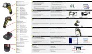
5<br />
4<br />
3<br />
1. RS-232 connector<br />
2. Power connector<br />
3. On/Off switch<br />
4. Scanner connector<br />
5. <strong>Mount</strong>ing knobs<br />
Figure 1-1<br />
<strong>Terminal</strong> Rear View<br />
RT<strong>5900</strong> SERIES <strong>Mobile</strong> <strong>Mount</strong> <strong>Radio</strong> <strong>Data</strong> <strong>Terminal</strong> 1-3<br />
2<br />
1
SECTION 1 " General Information<br />
On/Off Switch<br />
This is a push-push type switch located on the rear of the unit next to the<br />
power connector. Press the switch once to turn the unit ON. Press the<br />
switch a second time to turn the unit OFF. When the unit is turned ON, the<br />
backlight comes on and a message appears on the display.<br />
The Display<br />
The display shows current information such as your most recent scan or<br />
manual entry and certain information received from the host computer.<br />
User Interface menus and selections are also shown on the display whenever<br />
the operating system must be customized. A keyboard adjustable (see<br />
User Interface, Section 3 of this manual) backlight improves visibility of the<br />
display.<br />
1-4 RT<strong>5900</strong> SERIES <strong>Mobile</strong> <strong>Mount</strong> <strong>Radio</strong> <strong>Data</strong> <strong>Terminal</strong><br />
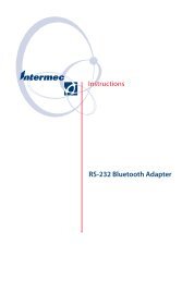
5<br />
6<br />
4<br />
1. Antenna<br />
2. Cursor (arrow) keys<br />
3. Numeric keys<br />
4. Miscellaneous keys<br />
5. Function keys<br />
6. Display<br />
Figure 1-2<br />
<strong>Terminal</strong> Front View<br />
1<br />
2<br />
3
Status Indicators<br />
SECTION 1 " General Information<br />
The display also shows a group of status indicators (icons). Their location<br />
on the display can be changed through the User Interface menus. These<br />
status indicators tell you:<br />
" cursor location by row and column number:<br />
01,02 = row 1, column 2<br />
" whether transmitting or receiving:<br />
transmit = arrow pointing away from radio<br />
receiving = arrow pointing toward radio<br />
" keyboard lockout:<br />
The Keyboard<br />
a large X = keyboard lockout ENABLED<br />
(host computer is preventing<br />
the keyboard from working)<br />
The keyboard has 58 keys that can produce up to 32 different functions.<br />
This is not as complicated as it sounds. For instance, there are 26 alphabet<br />
keys that combine with the SHIFT key to produce upper and lower case letters.<br />
Number Keys<br />
There are ten number (or “numeric”) keys arranged in a familiar ten-key<br />
format. Four cursor movement keys (right, left, up, down) are arranged in a<br />
diamond pattern next to the number keys.<br />
Function Keys<br />
Across the top of the keyboard are eight function keys (F-1 thru F-8). The<br />
function keys can be expanded by the use of the left shift and the right shift<br />
keys which are the two keys located below the cursor keys. These shift<br />
keys are color-coded to correspond with the functions that are printed to the<br />
left or right above each of the F-keys. Thus the left shift key expands the<br />
function keys to F-9 thru F-16, while the right shift key expands the functions<br />
to F-17 thru F-24.<br />
RT<strong>5900</strong> SERIES <strong>Mobile</strong> <strong>Mount</strong> <strong>Radio</strong> <strong>Data</strong> <strong>Terminal</strong> 1-5
SECTION 1 " General Information<br />
Miscellaneous Keys<br />
The key with the left-pointing arrow serves as a DELETE key, which eliminates<br />
one character to the left each time you press it.<br />
Use the SHIFT key to produce uppercase letters.<br />
The two keys above the SHIFT key have their functions printed above each<br />
key, and to the right of each key. The function to the right of each key is its<br />
unshifted value while the designation above each key is its shifted (use a<br />
SHIFT key) value.<br />
1-6 RT<strong>5900</strong> SERIES <strong>Mobile</strong> <strong>Mount</strong> <strong>Radio</strong> <strong>Data</strong> <strong>Terminal</strong>
Maintenance<br />
SECTION 1 " General Information<br />
Your terminal requires very little maintenance. Clean the terminal and the<br />
display periodically, and perform the daily checks listed below. If a failure<br />
message appears on the display, the <strong>Radio</strong> <strong>Data</strong> <strong>Terminal</strong> may need to be<br />
sent to an authorized service facility for repair or adjustment. Contact your<br />
authorized service representative for further instructions.<br />
Cleaning<br />
A recommended cleaner for the exterior of the <strong>Mobile</strong> <strong>Mount</strong> <strong>Radio</strong> <strong>Data</strong><br />
<strong>Terminal</strong> is MICRO-CLEAN II cleaner, made by Foresight International,<br />
Inc., 4887 F Street, Omaha, Nebraska 68127-0205 (phone:<br />
1-800-637-1344).<br />
Use a soft, lint-free cloth dampened with a quality glass cleaner to clean the<br />
display area.<br />
Daily Checks<br />
Each work day you should check to make sure that:<br />
" The antenna connector is secure.<br />
" All mounting knobs are tight.<br />
" The power cable is secure.<br />
" The scanner cable is secure.<br />
" The RS-232 communication cable (if so equipped) is secure.<br />
RT<strong>5900</strong> SERIES <strong>Mobile</strong> <strong>Mount</strong> <strong>Radio</strong> <strong>Data</strong> <strong>Terminal</strong> 1-7
SECTION 1 " General Information<br />
Factory Service<br />
When products must be shipped for repair:<br />
" Package in original shipping carton if possible.<br />
" Fill out a Product Service Information Card and include this card<br />
with the product.<br />
If the original shipping container is not available, appropriate packaging<br />
materials can be substituted. If in doubt, contact your authorized service<br />
representative for instructions.<br />
1-8 RT<strong>5900</strong> SERIES <strong>Mobile</strong> <strong>Mount</strong> <strong>Radio</strong> <strong>Data</strong> <strong>Terminal</strong>
Physical<br />
Table 1-1<br />
Specifications<br />
SECTION 1 " General Information<br />
Size: 2.4 inches X 8.9 inces active area (display)<br />
(6.0 cm. X 22.5 c. h x w)<br />
12.5 inches X 10.0 inches X 3.0 inches (enclosure)*<br />
(31.75 cm X 25.4 cm X 7.62 cm 1,w,d)<br />
*add 3.25 inches (8.25 cm) for antenna<br />
Weight: 13.75 pounds (6.24 kilograms) with bracket<br />
Keyboard: 58-key elastomer, tactile feel<br />
Environmental<br />
Operating Temperature: Standard: -4 to +122 °F (-20 to +50 °C)<br />
Low Temp: -22 to +122 °F (-30 to +50 °C)<br />
Storage Temperature: -22 to +158 °F (-30 to +70 °C)<br />
Humidity: 0-90 percent, non -condensing<br />
<strong>Radio</strong><br />
Spread method: direct sequence with multiple codes<br />
Frequency range: 902-928 MHz<br />
Power output: 1.0 watt<br />
Process gain: 17dBm<br />
Synchronization time: 250 µsec, maximum<br />
RF communication speed: 192 Kbps.<br />
Electrical<br />
Communication ports: 15-pin RS-232C 9-pin, 5-volt scanner interface<br />
Input voltage: supports 12-56 VDC systems<br />
Standards<br />
FCC: Meets FCC Class A limits<br />
EMI: MIL -STD -810D (designated to meet but not tested to NEMA-3)<br />
RT<strong>5900</strong> SERIES <strong>Mobile</strong> <strong>Mount</strong> <strong>Radio</strong> <strong>Data</strong> <strong>Terminal</strong> 1-9
SECTION 1 " General Information<br />
Specifications (continued)<br />
Power output: 2.0 watts, frequency modulated (FM)<br />
Frequency range: UHF Private Land <strong>Mobile</strong> <strong>Radio</strong> Service (crystal-controlled on<br />
assigned frequency)<br />
Receiver sensitivity: -90 dBm<br />
RF communication speed: 4800/9600 bps.<br />
1-10 RT<strong>5900</strong> SERIES <strong>Mobile</strong> <strong>Mount</strong> <strong>Radio</strong> <strong>Data</strong> <strong>Terminal</strong>
Section 2<br />
Installation Instructions<br />
" " " " " " " " " " " " " " " " " " " " " " " " " " " "<br />
Table 2-1<br />
Parts List<br />
kit NPN: 203-300-005<br />
Quantity Description Part #<br />
1 Fuse holder 315-062-001<br />
1 Fuse (15 amp, 250 volt) 315-064-001<br />
2 each <strong>Terminal</strong> ring (3/8”) 809-083-027<br />
1 External power cable 216-858-001<br />
2 each Bolt, 3/8” X 1-1/2” 800-099-001<br />
4 each Washer, 3/8” 803-099-001<br />
4 each Nut, 3/8” 802-099-001<br />
1 <strong>Mount</strong>ing bracket 699-781-001<br />
4 each Knob 805-460-002<br />
4 each Lock washer 803-027-000<br />
8 each Adjustable cable clamp 808-011-001<br />
8 each Sheet Metal Screw (#6 X 5/8”) 800-008-001<br />
RT<strong>5900</strong> SERIES <strong>Mobile</strong> <strong>Mount</strong> <strong>Radio</strong> <strong>Data</strong> <strong>Terminal</strong> 2-1
SECTION 2 " Installation Instructions<br />
Tools Required for Installation<br />
5 4<br />
2-2 RT<strong>5900</strong> SERIES <strong>Mobile</strong> <strong>Mount</strong> <strong>Radio</strong> <strong>Data</strong> <strong>Terminal</strong><br />
1. Fuse holder<br />
2. Fuse (15 amp, 250 volt)<br />
3. <strong>Terminal</strong> ring (3/8- inch)<br />
4. Cable clamp<br />
5. #6 sheet metal screw<br />
1<br />
3<br />
Figure 2-1<br />
Parts Identification<br />
1. Wire crimping and stripping tool.<br />
2. An electric drill, #26 drill bit.<br />
3. Common hand tools.<br />
2
Introduction<br />
SECTION 2 " Installation Instructions<br />
The <strong>Mobile</strong> <strong>Mount</strong> <strong>Radio</strong> <strong>Data</strong> <strong>Terminal</strong> can be mounted on motorized<br />
load-handling equipment such as a forklift. During this installation the<br />
power cable is wired directly to the vehicle battery or bank of batteries.<br />
This direct connection takes advantage of the filtering and regulation capabilities<br />
of storage batteries.<br />
The case and the power input of the terminal are electrically isolated from<br />
each other. This means it does not make any difference if the vehicle has a<br />
positive or negative ground electrical system. It is important to make sure<br />
that you connect all wiring exactly as instructed in this manual.<br />
A power supply-converter built into the <strong>Mobile</strong> <strong>Mount</strong> <strong>Radio</strong> <strong>Data</strong> <strong>Terminal</strong><br />
accepts a wide range (12 -56 volts d.c.) of input voltages (see Specifications).<br />
If the overall vehicle voltage exceeds 56 volts, you should tap into<br />
the bank of batteries at a point that is 56 volts or less.<br />
Since each situation or equipment type may pose unique requirements,<br />
mounting hardware selection and mechanical installation of the <strong>Mobile</strong><br />
<strong>Mount</strong> <strong>Radio</strong> <strong>Data</strong> <strong>Terminal</strong> shall be the responsibility of the installer. We<br />
recommend using 3/8-inch nuts and bolts, with flat and lock washers to<br />
install the mounting bracket.<br />
This kit contains nuts, bolts, washers, and two (3/8- inch) terminal rings for<br />
connecting the electrical cable directly to the vehicle battery. A waterproof<br />
in-line fuse holder must be installed between the positive battery terminal<br />
and the red wire in the power cable.<br />
RT<strong>5900</strong> SERIES <strong>Mobile</strong> <strong>Mount</strong> <strong>Radio</strong> <strong>Data</strong> <strong>Terminal</strong> 2-3
SECTION 2 " Installation Instructions<br />
Power Cable Routing<br />
Decide where you will mount the bracket for the <strong>Mobile</strong> <strong>Mount</strong> <strong>Radio</strong> <strong>Data</strong><br />
<strong>Terminal</strong>, then proceed with the instructions below.<br />
1. Completely install the power cable before connecting the unit.<br />
2. Begin installation by routing the cable from the general area where<br />
the terminal will be mounted. Work toward the battery.<br />
Take extra care to make sure:<br />
2-4 RT<strong>5900</strong> SERIES <strong>Mobile</strong> <strong>Mount</strong> <strong>Radio</strong> <strong>Data</strong> <strong>Terminal</strong><br />
" Cable routing will not endanger the operator.<br />
" Cable routing will not harm other equipment.<br />
" Cable routing does not invite damage to the cable.<br />
B CAUTION: Avoid having the cable pinched, stepped on, overheated, or snagged on passing<br />
equipment.<br />
3. Cut the power cable near the battery to eliminate the need for coiling<br />
excess cable.<br />
B CAUTION: Do not cut the cable too short to reach the battery terminals.<br />
4. Strip the gray power cable jacket back 12 -14 inches.<br />
Gray Power Cable<br />
216-675-001<br />
Strip the gray power cable jacket<br />
12-14 inches<br />
Black (or brown)<br />
Wire<br />
Figure 2-2<br />
Stripping the Power Cable Jacket<br />
Red Wire
Power Cable Assembly<br />
SECTION 2 " Installation Instructions<br />
The power cable must have an in-line fuse installed before making final<br />
connections to the vehicle battery. You must also crimp the 3/8 inch terminal<br />
rings to the wire ends.<br />
Assembling the In-line Fuse Holder<br />
The in-line fuse holder consists of a rubber boot, two crimp-type fuse clips,<br />
and a 15 amp fuse. Carefully follow these instructions to assemble the inline<br />
fuse holder.<br />
1. Locate the in-line fuse holder components.<br />
2. Cut the red wire in the gray power cable, midway between its end<br />
and the gray cable jacket. Save the 6-7 inch length of red wire.<br />
3. Strip approximately 1/4-inch of insulation from the red wire that extends<br />
from the power cable; also strip 1/4-inch of insulation from<br />
both ends of the 6 inch length of red wire saved in step #2.<br />
4. Slide the longer portion of the in-line fuse holder boot (yellow rubber)<br />
over the red wire that extends from the power cable.<br />
5. Slip a fuse clip onto this wire and crimp the clip onto the wire.<br />
6. Slip the remaining fuse clip onto one end of the 6 inch wire saved<br />
from step #2 and crimp securely.<br />
7. Slide this wire into the other half of the fuse holder boot. Insert the<br />
fuse into the fuse clips and snap the halves of the fuse holder boot<br />
together.<br />
RT<strong>5900</strong> SERIES <strong>Mobile</strong> <strong>Mount</strong> <strong>Radio</strong> <strong>Data</strong> <strong>Terminal</strong> 2-5
SECTION 2 " Installation Instructions<br />
2-6 RT<strong>5900</strong> SERIES <strong>Mobile</strong> <strong>Mount</strong> <strong>Radio</strong> <strong>Data</strong> <strong>Terminal</strong><br />
5<br />
6<br />
4<br />
1. Fuse clips<br />
2. Red wire (6 -7 inches)<br />
3. Fuse holder ”boot”<br />
4. Red wire<br />
5. Gray power cable<br />
6. Brown (or Black) wire<br />
Figure 2-3<br />
Assembling the In-Line Fuse Holder<br />
3<br />
1<br />
2
Terminating Wire Ends<br />
SECTION 2 " Installation Instructions<br />
Crimp 3/8-inch terminal rings to the stripped end of the brown wire and to<br />
the red wire from the fuse holder. See the battery drawing and instructions<br />
for recommended assembly to connect the cable to the vehicle battery.<br />
1. Strip approximately 1/4” of insulation from the brown (or black) wire<br />
from the power cable.<br />
2. Crimp the 3/8” terminal ring onto this wire.<br />
3. Fasten the brown (or black) wire to the negative battery terminal.<br />
4. Crimp a 3/8” terminal ring onto the red wire from the end of the inline<br />
fuse holder<br />
5. Fasten this wire to the positive battery terminal.<br />
Insert fuse into clips.<br />
Snap fuse holder<br />
together.<br />
-<br />
Figure 2-4<br />
Terminating Wire Ends<br />
RT<strong>5900</strong> SERIES <strong>Mobile</strong> <strong>Mount</strong> <strong>Radio</strong> <strong>Data</strong> <strong>Terminal</strong> 2-7<br />
+
SECTION 2 " Installation Instructions<br />
Side <strong>Mount</strong> Battery Connection<br />
2-8 RT<strong>5900</strong> SERIES <strong>Mobile</strong> <strong>Mount</strong> <strong>Radio</strong> <strong>Data</strong> <strong>Terminal</strong><br />
1<br />
2<br />
7<br />
1. Bolt<br />
2. Nut<br />
3. Vehicle battery<br />
4. Vehicle battery cable<br />
5. In-line fuse holder<br />
6. <strong>Terminal</strong> ring<br />
7. Washers<br />
Figure 2-5<br />
Side <strong>Mount</strong> Battery<br />
1. Remove both battery cable retaining screws from the vehicle battery.<br />
2. Screw a 3/8” nut as far as it will go onto a 3/8” x 1-1/2” bolt.<br />
3. Slip a 3/8” flat washer onto the bolt.<br />
4. Slide the positive (red wire) terminal ring of the 7524Norand power<br />
cable onto the bolt.<br />
5. Slip a second 3/8” flat washer onto the bolt.<br />
6. Slide the vehicle positive battery cable onto the bolt.<br />
7. Thread the bolt assembly into the positive battery terminal; tighten<br />
securely.<br />
8. Tighten the nut installed in step #2 against the washers and battery<br />
terminals.<br />
Repeat steps #2 thru #8 for the negative wire (black or brown) from the<br />
power cable, hooking up the wires to the negative battery terminal.<br />
5<br />
4<br />
6<br />
3
Power Cable Connection<br />
Top <strong>Mount</strong> Battery Connection<br />
1<br />
6<br />
5<br />
SECTION 2 " Installation Instructions<br />
1. 3/8” nut<br />
2. Vehicle battery<br />
3. Vehicle battery cable<br />
4. Fuse link<br />
5. 3/8” X 1-1/2” bolt<br />
6. 3/8” washers<br />
Figure 2-6<br />
Top <strong>Mount</strong> Battery<br />
Connect the positive (red wire) terminal ring from the power cable to the<br />
positive battery terminal, as shown, using a 3/8” x 1-1/2” bolt, a flat washer<br />
on each side of the terminal ring, and two 3/8” nuts. Connect the negative<br />
(black or brown wire) terminal ring from the power cable to the negative<br />
battery terminal, using a 3/8” x 1-1/2” bolt, a flat washer on each side of the<br />
terminal ring, and two 3/8” nuts.<br />
Secure the Power Cable<br />
Secure the power cable every 18 inches with adjustable cable clamps. Work<br />
from the battery, toward the mounting area for the mobile mount radio data<br />
terminal. Remove the paper backing from a clamp and stick the clamp in<br />
place while drilling a pilot hole with a #26 drill bit. Use #6 sheet metal<br />
screws to permanently hold clamps in place.<br />
RT<strong>5900</strong> SERIES <strong>Mobile</strong> <strong>Mount</strong> <strong>Radio</strong> <strong>Data</strong> <strong>Terminal</strong> 2-9<br />
4<br />
2<br />
3
SECTION 2 " Installation Instructions<br />
<strong>Mount</strong>ing the <strong>Terminal</strong><br />
The mounting kit consists of a pre-drilled mounting bracket, four mounting<br />
knobs, and four lock washers. Use at least two sets of 3/8” bolts, nuts, flat<br />
washers and lock washers to install the mounting bracket. Since installations<br />
can vary and may require different bolt lengths, that hardware is not<br />
furnished in this kit and must be purchased locally. <strong>Mount</strong>ing bolts should<br />
be evenly spaced.<br />
Install the mounting bracket and tighten all hardware securely. Support the<br />
<strong>Mobile</strong> <strong>Mount</strong> <strong>Radio</strong> <strong>Data</strong> <strong>Terminal</strong> so the standoffs line up with the desired<br />
holes in the mounting bracket. Note that the upper holes are arranged in an<br />
arc to adjust the viewing angle of the unit.<br />
Place a lock washer (provided in kit) onto each mounting knob, then screw<br />
knobs through the holes and into the standoffs. Tighten knobs securely to<br />
hold the terminal in place.<br />
2-10 RT<strong>5900</strong> SERIES <strong>Mobile</strong> <strong>Mount</strong> <strong>Radio</strong> <strong>Data</strong> <strong>Terminal</strong><br />
1. Bracket<br />
2. Lock washer<br />
3. Knob<br />
4. Standoffs<br />
Figure 2-7<br />
<strong>Mount</strong>ing the <strong>Terminal</strong><br />
4<br />
1<br />
2<br />
3
Connections to the <strong>Terminal</strong><br />
4<br />
3<br />
SECTION 2 " Installation Instructions<br />
1. 15-pin connector<br />
(communication)<br />
2. Power connector<br />
3. On/Off switch<br />
4. 9-pin connector<br />
(scanner)<br />
Figure 2-8<br />
Cable Connections<br />
Connect cables as shown in Figure 2-8. Simply align each cable connector<br />
to the appropriate connector on the terminal and push them together. In<br />
addition, you must turn the power cable connector clockwise to lock it in<br />
place.<br />
The 15-pin connector may be used for peripheral devices such as a printer<br />
or a scale. Not all installations use this connector.<br />
ON/OFF Button<br />
Push this button once to turn the <strong>Mobile</strong> <strong>Mount</strong> <strong>Radio</strong> <strong>Data</strong> <strong>Terminal</strong> on.<br />
Push the button a second time to shut the unit off.<br />
RT<strong>5900</strong> SERIES <strong>Mobile</strong> <strong>Mount</strong> <strong>Radio</strong> <strong>Data</strong> <strong>Terminal</strong> 2-11<br />
2<br />
1
SECTION 2 " Installation Instructions<br />
Desktop Installation Kit Instructions<br />
2-12 RT<strong>5900</strong> SERIES <strong>Mobile</strong> <strong>Mount</strong> <strong>Radio</strong> <strong>Data</strong> <strong>Terminal</strong><br />
Table 2-2<br />
Parts List<br />
kit NPN: 203-300-006<br />
Quantity Description Part #<br />
1 <strong>Mount</strong>ing bracket 699-781-001<br />
4 Knobs 805-460-002<br />
4 Lockwashers 803-027-000<br />
8 Adjustable clamps 808-011-001<br />
8 Self-tapping screws (pan head, #6<br />
x 5/8”)<br />
800-008-001<br />
1 External power cable 216-860-001<br />
1 AC power cord 321-054-001<br />
1 NC4000 power supply 851-013-002<br />
Kit Description<br />
This kit contains a power supply, power cables, and mechanical hardware to<br />
permit desktop (nonvehicular) operation of the <strong>Mobile</strong> <strong>Mount</strong> <strong>Radio</strong> <strong>Data</strong><br />
<strong>Terminal</strong>.<br />
The power cable furnished in this kit has the correct connector on one end to<br />
fit the terminal; the other end of the cable has a push-in/screw-collar connector<br />
to fit the NC4000 Power Supply.
Instructions<br />
<strong>Mount</strong>ing Bracket<br />
SECTION 2 " Installation Instructions<br />
Experiment with the terminal and the mounting bracket to determine the<br />
bracket arrangement that will provide you with the best viewing angle. Use<br />
two knobs and two lock washers on each side to attach the bracket to the<br />
terminal. Use 3/8-inch hardware if you will be attaching the mounting<br />
bracket to a desk, counter top, or shelving.<br />
NC4000 Power Supply<br />
Locate and identify the 10-foot external DC power cable (NPN:<br />
216-860-001) in this kit along with the AC power cord. One end of the DC<br />
power cable has a metal collar and plugs into the three-pin connector<br />
(shown) on the NC4000 Power Supply.<br />
Connect the DC Power Cable<br />
1. Align the pins and push the round connector into the power supply.<br />
2. Screw the collar into place. Do not overtighten.<br />
3. Route the cable toward the terminal.<br />
4. Align the cable connector to the power jack and push the connector<br />
firmly into the jack.<br />
5. Turn the collar on this connector clockwise to lock it in place.<br />
6. Use the cable clamps and screws in this kit to secure the cable, making<br />
a neat installation.<br />
Connect the AC Power Cable<br />
1. Plug the female end of this cable into the NC4000.<br />
2. Plug the male end of this cable into a standard, grounded, three-prong<br />
wall outlet.<br />
Do not use an adapter to defeat the electrical ground.<br />
The installation is complete.<br />
RT<strong>5900</strong> SERIES <strong>Mobile</strong> <strong>Mount</strong> <strong>Radio</strong> <strong>Data</strong> <strong>Terminal</strong> 2-13
SECTION 2 " Installation Instructions<br />
DC POWER CONNECTOR<br />
(USE CABLE #216-860 -001)<br />
2-14 RT<strong>5900</strong> SERIES <strong>Mobile</strong> <strong>Mount</strong> <strong>Radio</strong> <strong>Data</strong> <strong>Terminal</strong><br />
AC POWER CONNECTOR<br />
(CABLE TO WALL OUTLET)<br />
Figure 2-9<br />
The NC4000 Power Supply
Section 3<br />
User Interface Instructions<br />
" " " " " " " " " " " " " " " " " " " " " " " " " " " "<br />
Introduction<br />
The user interface for the <strong>Mobile</strong> <strong>Mount</strong> <strong>Radio</strong> <strong>Data</strong> <strong>Terminal</strong> consists of<br />
the keyboard, the display, and the operating system (program) that allows<br />
you to customize the unit operation.<br />
The first section of this manual has already described the keyboard and the<br />
display; this section of the manual tells you how to use the operating system<br />
itself.<br />
" NOTE: The application program (unique to your specific business or industry) is entirely<br />
separate from the operating system and the keystrokes may have slightly different<br />
meanings between the two types of programs.<br />
Since the operating system is presented to you as a series of menus on the<br />
display, the following pages are arranged in a similar fashion.<br />
Conventions<br />
Conventions are the rules to follow when going through the menus and<br />
making (or not making) various choices. These rules are important to understand<br />
and remember because they apply to most of the menus within the<br />
operating system. If a particular menu requires a unique response, this is<br />
noted in the text that goes with that menu.<br />
The darkened (e.g., darkened) word or phrase below represents the key(s)<br />
you must press, followed by an explanation of what that action accomplishes.<br />
RT<strong>5900</strong> SERIES <strong>Mobile</strong> <strong>Mount</strong> <strong>Radio</strong> <strong>Data</strong> <strong>Terminal</strong> 3-1
SECTION 3 " User Interface Instructions<br />
The Keyboard<br />
Accessing the Menu<br />
Press the LEFT SHIFT and then the MENU (SPACE) key to access the<br />
Main Menu.<br />
ENTER Key<br />
Press this key to go to the next whole (parent) menu. Multiple presses of<br />
this key cause the program to act as a loop, taking you back, eventually, to<br />
the starting point.<br />
1 (or 2, 3, 4, 5, etc.)<br />
Many menus have numbered choices. You must press the corresponding<br />
number to make a selection. If that menu remains on the display, the choice<br />
will be high-lighted (meaning that particular function or choice is turned<br />
ON) and you can then make additional selections from the same menu. You<br />
must press the ENTER key to confirm the settings and exit this type of<br />
menu.<br />
In some cases, when you press a number to make a selection, a different<br />
menu (submenu) displays. These allow you to modify the choice made in<br />
the parent menu. After the modification(s), you may (depending on the<br />
menu and function) be permitted to return to the parent menu to make additional<br />
selections.<br />
Other menus require a numerical input but do not necessarily have simple<br />
choices such as 1, 2, 3, 4, etc. Instead, you may have to enter a number<br />
from 0 -32, or 1 -255, or some other figure. These instances will be detailed<br />
in the text that applies to those menus or in the menu drawings.<br />
UP Arrow and DOWN Arrow<br />
Use these keys to adjust the length and volume of the audible (buzzer) functions,<br />
Keyclick and Error Tone. The arrow keys adjust other functions such<br />
as the contrast on the display and the screen size.<br />
Arrow keys can be made to function more efficiently, in many cases, by<br />
pressing the FUNC or ALT key, then pressing the desired arrow key.<br />
Entry Errors<br />
The message “Range is” displays and the numerical value of the range is<br />
shown. You must enter a value within that range.<br />
3-2 RT<strong>5900</strong> SERIES <strong>Mobile</strong> <strong>Mount</strong> <strong>Radio</strong> <strong>Data</strong> <strong>Terminal</strong>
Right Shift/Space<br />
SECTION 3 " User Interface Instructions<br />
Press the RIGHT SHIFT key and then the SPACE key to change the size<br />
of displayed text from large to small, or vice -versa.<br />
4<br />
F6 F7 F8<br />
S<br />
H<br />
I<br />
F<br />
T<br />
SHIFT key<br />
Use this key to shift the alpha<br />
keys between upper and lower case.<br />
MENU<br />
SPACE<br />
1. Arrow Keys<br />
2. Right Shift<br />
3. Left Shift<br />
4. Alpha Shift<br />
MENUS<br />
To access user menus,<br />
press the LEFT shift key,<br />
then the SPACE (menu) key.<br />
RT<strong>5900</strong> SERIES <strong>Mobile</strong> <strong>Mount</strong> <strong>Radio</strong> <strong>Data</strong> <strong>Terminal</strong> 3-3<br />
3<br />
1<br />
2
SECTION 3 " User Interface Instructions<br />
Main Menu<br />
Press the LEFT SHIFT and then the MENU (SPACE) key to call up the<br />
main menu. The main menu appears on the display. You can then enter a<br />
number (1 thru 7) to make a selection. Making a selection of 2, 3, 4, 5, or 7<br />
will cause that menu to display. If you select number 1, you must enter the<br />
password (CR52401) for that menu to become available to you.<br />
Selection 1, Set-Up Parms, and <strong>Radio</strong> Tests (first part of selection 4, Tests),<br />
are password-protected to guard against unwanted changes or loss of data.<br />
If the display asks for a password, you must enter a combination of seven<br />
(7) alpha (letters) or numeric (number) characters to access the protected<br />
menu.<br />
Exit Menus<br />
When you are done making changes or adjustments to your terminal, press<br />
number 6 (Exit Menus) to return to normal operation.<br />
If the main menu is not displayed, press the ENTER key several times until<br />
it does, then press number 6 when the main menu displays to return to normal<br />
operation.<br />
1)<br />
2)<br />
3)<br />
4)<br />
5)<br />
6)<br />
7)<br />
3-4 RT<strong>5900</strong> SERIES <strong>Mobile</strong> <strong>Mount</strong> <strong>Radio</strong> <strong>Data</strong> <strong>Terminal</strong><br />
MAIN MENU<br />
Set -up Parms<br />
LCD Parms<br />
Beeper Setup<br />
Tests<br />
Version Info<br />
Exit Menus<br />
More
Enter Password<br />
Set -up Parms<br />
1 2<br />
1) <strong>Radio</strong> #<br />
2) Barcode Parms<br />
3) Protocol Opts<br />
4) Display Opts<br />
5) <strong>Radio</strong> Comm<br />
6) Cold Start<br />
LCD Parms<br />
1) LCD Contrast<br />
2) Screen Size<br />
3) Screen Mode<br />
4) Annunciators<br />
5) Backlight<br />
6) Key Uppercase<br />
Keyboard Opts<br />
1) Type -Ahead<br />
SECTION 3 " User Interface Instructions<br />
3<br />
1)<br />
2)<br />
3)<br />
4)<br />
5)<br />
6)<br />
7)<br />
Beeper Setup<br />
1)<br />
2) Keyclick<br />
Error Tone<br />
Main Menu<br />
Set -up Parms<br />
LCD Parms<br />
Beeper Setup<br />
Tests<br />
Version Info<br />
Exit Menus<br />
More<br />
4<br />
Tests<br />
1) Peripherals<br />
2) Converters<br />
3) Memory View<br />
4) Packet Driver<br />
5) Numbers<br />
Main Menu 2<br />
(choice #7, ”More”)<br />
1)<br />
2)<br />
3)<br />
4)<br />
Main Menu 2<br />
Keyboard Opts<br />
Save Parms<br />
Cloning Opts<br />
Session Menu<br />
Enter Password<br />
Save Parms<br />
Working . . .<br />
Please Wait<br />
Version Info<br />
FWP59XXX<br />
5 7<br />
Version number<br />
Date dd mnth yy<br />
Cloning Opts<br />
1) Clone Prgms<br />
2) Clone Parms<br />
3) Receive Parms<br />
See below<br />
RT<strong>5900</strong> SERIES <strong>Mobile</strong> <strong>Mount</strong> <strong>Radio</strong> <strong>Data</strong> <strong>Terminal</strong> 3-5
SECTION 3 " User Interface Instructions<br />
Main Menu<br />
Set Parameters<br />
This menu is password protected to prevent unauthorized changes to the<br />
way the terminal operates, or to prevent loss of data. You can change the<br />
following parameters for the current (foreground) session only:<br />
" the number that designates this radio<br />
" barcode parameters<br />
" protocol options<br />
" display options<br />
See Session Menu to determine or change the current session.<br />
<strong>Radio</strong> #<br />
This submenu (selection #1 in the Set-Up Parms menu) displays the current<br />
terminal identification number. Changing the number restarts the terminal,<br />
which then reports the new number to the host computer.<br />
All previously made terminal setup choices remain intact when a restart is<br />
forced as a result of changing the terminal identification number.<br />
Advanced Setup options under the <strong>Radio</strong> # menu are used to define parameters<br />
for communicating to multiple host systems or to systems that support<br />
multiple data streams.<br />
Barcode Parms (goes directly to Scanner Type menu)<br />
This selection (choice #2 in the Set Parameters menu) allows you to designate<br />
if the terminal is connected to a scanner, and if so, to specify the type<br />
of scanner. You are then guided through additional menus to customize the<br />
way your terminal responds to various bar code types.<br />
3-6 RT<strong>5900</strong> SERIES <strong>Mobile</strong> <strong>Mount</strong> <strong>Radio</strong> <strong>Data</strong> <strong>Terminal</strong>
<strong>Radio</strong> #<br />
Enter Unit<br />
Number:<br />
xxx<br />
Press A for<br />
Advanced Setup<br />
Scanner Type<br />
1) No Scanner<br />
2) Wand<br />
3) Laser<br />
4) Wand Emulate<br />
Protocol Opts<br />
1) Host View Size<br />
2) <strong>Data</strong> Stream<br />
3) Extended Cmds<br />
4) 5250<br />
5) 3270<br />
6) VT220<br />
7) Native<br />
SECTION 3 " User Interface Instructions<br />
Set Up Parms<br />
1)<br />
2)<br />
3)<br />
4)<br />
5)<br />
6)<br />
1<br />
2<br />
3<br />
<strong>Radio</strong> #<br />
Barcode Parms<br />
Protocol Opts<br />
Display Opts<br />
<strong>Radio</strong> Comm<br />
Cold Start<br />
6<br />
5<br />
4<br />
Cold Start<br />
Enter ”Y”<br />
to Cold Start<br />
<strong>Terminal</strong>:<br />
NOT<br />
user<br />
accessible<br />
Display Opts<br />
1)<br />
2) Cursor Mode<br />
3) Remote Disp<br />
" NOTE: Parameter settings you make only apply to the current session. If more than one<br />
session is available to you, use the Session Menu (#4 in Main Menu 2) to verify or<br />
change the current session before making parameter settings.<br />
RT<strong>5900</strong> SERIES <strong>Mobile</strong> <strong>Mount</strong> <strong>Radio</strong> <strong>Data</strong> <strong>Terminal</strong> 3-7
SECTION 3 " User Interface Instructions<br />
Advanced Setup (<strong>Radio</strong> #)<br />
This sub menu can be used to define parameters for communicating in a<br />
multiple host environment. In the “Advanced Setup” menu (SST and OWL<br />
only), you designate the session to be modified in the following menus.<br />
Note that all of the menu functions shown may not actually be available to<br />
you: this depends upon whether or not multiple hosts exist, and whether or<br />
not different data streams are supported.<br />
The LAN ID range is 0 -254 with the RM60/70 radios, and is 0 -15 with<br />
RM80/90 radios. The <strong>Radio</strong> Configuration option allows you to configure<br />
RM60/70-equipped terminals for specific modes and frequencies.<br />
Host A<br />
The designator (“Host A”) will display “B or ”C”, etc., depending upon the<br />
selection made in the previous menu.<br />
With the first of these menus, you can designate the data stream for this session<br />
only. You must specify the data stream for each different session.<br />
The second of these menus allows you to specify the radio (“unit”) number<br />
to be used for this session only. This number is specific to this host and session<br />
type. If you create a second or third session, a different radio number<br />
can be entered for each session.<br />
The third menu displays the data stream previously selected for this particular<br />
session and the radio number designation. This menu allows you to designate<br />
the target host for this particular session.<br />
3-8 RT<strong>5900</strong> SERIES <strong>Mobile</strong> <strong>Mount</strong> <strong>Radio</strong> <strong>Data</strong> <strong>Terminal</strong>
SECTION 3 " User Interface Instructions<br />
" NOTE: Selections in these menus apply only to the current session. Use the Session Menu<br />
to verify or change the current session.<br />
Host A<br />
Enter Unit<br />
Number: xxx<br />
<strong>Radio</strong> #<br />
Enter Unit<br />
Number: xx<br />
Press A for<br />
Advanced Setup<br />
Advanced Setup<br />
LAN<br />
X<br />
(A)<br />
Advanced Setup<br />
<strong>Radio</strong> Config#<br />
Advanced Setup<br />
1) Host A<br />
2) Host B<br />
3) Host C<br />
Host A<br />
1) Native<br />
2) 3270<br />
3) 5250<br />
4) VT220<br />
ENTER<br />
XXX<br />
ENTER<br />
ENTER<br />
This number is<br />
specific to the host<br />
and session type<br />
for this designated<br />
session.<br />
ENTER<br />
‘ADVANCED SETUP’ AP-<br />
PLIES TO SST & OWL<br />
ONLY<br />
Enter a number, 0 thru 7<br />
RM60/70 <strong>Radio</strong> <strong>Terminal</strong> Configuration<br />
Value Resulting Settings<br />
0 Mode 1, 225Kbps<br />
1 Mode 1, 225 Kbps<br />
2 Mode 2, Channel 10, 90 Kbps<br />
3 Mode 2, Channel 15, 90 Kbps<br />
4 Mode 2, Channel 20, 90 Kbps<br />
5 Mode 2, Channel 25, 90 Kbps<br />
6 Mode 2, Channel 30, 90 Kpbs<br />
7 Mode 2, Channel 35, 90 Kbps<br />
8 Mode 2, Channel 40, 90 Kbps<br />
9 Mode 3, 450 Kbps<br />
Enter the name of the target host.<br />
Host A<br />
(host emulation)<br />
Unit XXX<br />
Enter Host Name:<br />
xxxx<br />
RT<strong>5900</strong> SERIES <strong>Mobile</strong> <strong>Mount</strong> <strong>Radio</strong> <strong>Data</strong> <strong>Terminal</strong> 3-9
SECTION 3 " User Interface Instructions<br />
Barcode Parms (continued)<br />
The Barcode Parms flowchart shows four screens (e.g., Scanner Type, Scan<br />
Options, Scan Options [1], Scan Options [2], plus their option menus). You<br />
must press the ENTER key to pass from Scanner Type to Scan options, and<br />
again to pass from one scan options menu to the next. After you have made<br />
all choices and options, press the ENTER key while in the Scan Options<br />
menu to return to the Set Parameters parent menu.<br />
Scanner Type<br />
Lets you designate the type of scanner that is connected to the terminal.<br />
With selection 1, “No Scanner,” you can verify or pre-set the various scanner<br />
and barcode options, with the intent of connecting a scanner at a later<br />
time. At that time, you must designate the scanner type so that the terminal<br />
recognizes and responds to the scanner. Enter a number, 1 thru 5, then press<br />
the ENTER key to go to the next menu.<br />
Scan Options<br />
Allows bar code industry standard options (Redundancy, Mod 10 Chk, Concatenate,<br />
etc.) to be enabled or disabled, and designates how the terminal<br />
handles scanner-derived data (BC Type Char, Auto Tab Scan, and Auto Enter<br />
Scan). Settings for the data handling options will be specified by the<br />
host programmer.<br />
Within this menu, Scan Timeout (choice #7), allows you to specify the scanner<br />
timeout period. You can select from 1 -200 seconds. For instance,<br />
shorten the timeout period when using a proximity scanner to reduce error<br />
scans; when using a long-range scanner it may be helpful to extend the<br />
timeout period to allow for more accurate scanner aiming.<br />
3-10 RT<strong>5900</strong> SERIES <strong>Mobile</strong> <strong>Mount</strong> <strong>Radio</strong> <strong>Data</strong> <strong>Terminal</strong>
Barcode Parms<br />
1)<br />
2)<br />
3)<br />
4)<br />
5)<br />
1<br />
Scanner Type<br />
No Scanner<br />
Wand<br />
Laser<br />
Wand Emulate<br />
Auto Detect<br />
2<br />
Scan Options<br />
1)<br />
2)<br />
3)<br />
4)<br />
5)<br />
6)<br />
7)<br />
1)<br />
2)<br />
3)<br />
4)<br />
5)<br />
Redundancy<br />
MOD 10 Chk<br />
Concatenate<br />
BC Type Char<br />
Stream Scan<br />
Scan All Flds<br />
Scan Timeout<br />
3<br />
Scan Options<br />
UPC<br />
EAN<br />
Code 39<br />
Code 128<br />
Codabar<br />
4<br />
Scan Options<br />
1)<br />
2)<br />
3)<br />
4)<br />
5)<br />
6)<br />
Plessey<br />
STR 2of5<br />
INT 2of5<br />
CI 2of5<br />
Code 11<br />
Code 93<br />
SECTION 3 " User Interface Instructions<br />
Specify scanner timeout<br />
period. Range is<br />
1 -200 seconds.<br />
Seconds<br />
XXX<br />
See Scan Options (1)<br />
See Length options<br />
See Scan Options (2)<br />
See Length options<br />
Set-up Parms menu<br />
Scan Timeout<br />
RT<strong>5900</strong> SERIES <strong>Mobile</strong> <strong>Mount</strong> <strong>Radio</strong> <strong>Data</strong> <strong>Terminal</strong> 3-11
SECTION 3 " User Interface Instructions<br />
Scan Options [1]<br />
Designates the bar codes to be recognized by the terminal. When you select<br />
a bar code type, an option menu (see Scan Options [1] ) displays to further<br />
define your choice. If you will not be selecting a bar code type within the<br />
Scan Options [1] menu, press the ENTER key to go directly to the Scan<br />
Options [2] menu.<br />
When all of the options for a particular bar code have been selected, you<br />
must press the ENTER key. The next menu allows you to set the minimum<br />
and maximum lengths (of the selected bar code) that will be recognized by<br />
the terminal. After designating those lengths, press the ENTER key to return<br />
to the Scan Options [1] menu, where you can make another selection.<br />
When all desired bar codes, their options, and their lengths have been set in<br />
the scanner options menus, press the ENTER key to move to the Scan Options<br />
[2] menu.<br />
Scan Options [2]<br />
Designates additional bar codes to be recognized by the terminal. When a<br />
bar code type is selected, an options menu displays to further define your<br />
choice. If you will not be selecting a bar code type within the Scan Options<br />
[2] menu, press the ENTER key to return to the Set Parameters menu.<br />
When you have selected all of the options for a particular bar code, you<br />
must press the ENTER key. The next menu allows you to set the minimum<br />
and maximum lengths of the selected bar code that will be recognized.<br />
Press the ENTER key to return to the Scan Options [2] menu, where you<br />
can make a second (or third, fourth, etc.) selection. When all desired bar<br />
codes, their options, and their lengths have been set in this menu, press the<br />
ENTER key to return to the Set Parameters menu.<br />
You can now make another selection from the Set Parameters menu (press a<br />
number, 1 thru 7), or press the ENTER key to return to the Main Menu.<br />
3-12 RT<strong>5900</strong> SERIES <strong>Mobile</strong> <strong>Mount</strong> <strong>Radio</strong> <strong>Data</strong> <strong>Terminal</strong>
UPC<br />
1) Enabled<br />
2) Add -on 2<br />
3) Add -on 5<br />
4 Sys 1 UPCE<br />
5) Sys 2 UPCE<br />
6) Expand E to A<br />
EAN<br />
1) Enabled<br />
2) Add -on 2<br />
3) Add -on 5<br />
4) Expand 8to13<br />
Code 39<br />
1) Enabled<br />
2) Chk Digit<br />
3) Extended<br />
4) Encoded<br />
5) Auto -Encoded<br />
6) Relax Std<br />
7) Full ASCII<br />
Plessey<br />
1) Enabled<br />
2) Mod 10 Chk<br />
3) Mod 1 Chk<br />
Str 2of5<br />
1) Enabled<br />
2) Disabled<br />
Int 2of5<br />
1) Enabled<br />
2) Chk Digit<br />
CI 2of5<br />
1) Enabled<br />
2) Disabled<br />
SECTION 3 " User Interface Instructions<br />
Relax Code 39<br />
1) Quiet Zone<br />
2) <strong>Data</strong> Decode<br />
3) Element Decode<br />
4) START Decode<br />
Code 128<br />
1) Enabled<br />
2) UCC/EAN<br />
Codabar<br />
1) Codabar<br />
2) ABC codabar<br />
Code 11<br />
1) Enabled<br />
2) Chk Digit1<br />
3) Chk Digit 2<br />
Code 93<br />
1) Enabled<br />
2) Disabled<br />
Scan<br />
Options<br />
[1]<br />
Scan<br />
Options<br />
[2]<br />
RT<strong>5900</strong> SERIES <strong>Mobile</strong> <strong>Mount</strong> <strong>Radio</strong> <strong>Data</strong> <strong>Terminal</strong> 3-13
SECTION 3 " User Interface Instructions<br />
Other Scan Options [1] & [2]<br />
After making your selection from the scan options menus, an options menu<br />
for the chosen bar code type displays. Press the corresponding number(s) to<br />
highlight your choice(s) and make the selection(s).<br />
Then, press the ENTER key to display the Lengths menu, where you can<br />
select minimum and maximum bar code lengths. The display returns to the<br />
Scan Options when you press the ENTER key.<br />
You can then make another selection within the Scan Options menu, repeating<br />
the selection processes described above for each additional menu<br />
choice.<br />
Lengths Options<br />
After making your selection from the Scan Options menus, the display progresses<br />
to the XXXXXXX Opts menu (“XXXXXXX” will be the name of<br />
the parent menu such as “UPC Opts”) where you can select bar code length<br />
options.<br />
The first length menu shows only one parameter (Enter Max Len: XX); the<br />
second length menu displays the original parameter plus the current (second)<br />
one. The Length menu expands, as shown, as you press the ENTER<br />
key.<br />
Numerical entries, if any, must be between 1 and 99. Illogical entries, such<br />
as setting the minimum greater than the maximum, are not allowed.<br />
3-14 RT<strong>5900</strong> SERIES <strong>Mobile</strong> <strong>Mount</strong> <strong>Radio</strong> <strong>Data</strong> <strong>Terminal</strong>
BARCODE LENGTH ME-<br />
NUS<br />
XXXXXXX<br />
Max Length:XX<br />
XXXXXXX<br />
Max Length:XX<br />
Min Length: XX<br />
XXXXXXX<br />
Max Length:XX<br />
Min Length: XX<br />
Fix Length 1: XX<br />
XXXXXXX<br />
Max Length:XX<br />
Min Length: XX<br />
Fix Length 1: XX<br />
Fix Length 2: XX<br />
XXXXXXX<br />
Max Length:XX<br />
Min Length: XX<br />
Fix Length 1: XX<br />
Fix Length 2: XX<br />
Fix Length 3: XX<br />
XXXXXXX<br />
Max Length:XX<br />
Min Length: XX<br />
Fix Length 1: XX<br />
Fix Length 2: XX<br />
Fix Length 3: XX<br />
Fix Length 4: XX<br />
SECTION 3 " User Interface Instructions<br />
Screens below allow you to drop<br />
up to 15 leading or trailing characters<br />
from the bar code. Typically<br />
used to remove check digits<br />
or non-significant zeros.<br />
XXXXXXX<br />
Drop Leading: XX<br />
XXXXXXX<br />
Drop Leading: XX<br />
Drop Trailing: XX<br />
RT<strong>5900</strong> SERIES <strong>Mobile</strong> <strong>Mount</strong> <strong>Radio</strong> <strong>Data</strong> <strong>Terminal</strong> 3-15
SECTION 3 " User Interface Instructions<br />
Protocol Options<br />
Host View Size<br />
The default value for display width is shown. This option tells the terminal<br />
that the host computer sends information in a different size or format.<br />
When the width line is highlighted, you can enter a number, 1 thru 80, to<br />
change the width of the display.<br />
<strong>Data</strong> Stream<br />
Specifies the terminal emulation used by the host computer to communicate<br />
to the terminal. Choices are: (1) Native, (2) 3270, (3) 5250, or (4) VT220.<br />
Extended (5250) CMDS<br />
These commands are used by the terminal for functions that are not normally<br />
available to the host computer. With this option enabled, the host computer<br />
can change these parameters on the terminal:<br />
" RS-232 communications (e.g., printer)<br />
" bar code options<br />
" display screen and font size<br />
VT220/3270/5250 Options<br />
" Keyboard Lock locks the keyboard when the PA-1, PA-2, or the<br />
CLEAR key is pressed.<br />
" Auto Tab Scan causes the display to automatically move to the next<br />
field after a good scan.<br />
" Beep On Error provides warning of an error while allowing work to<br />
progress (keyboard is normally locked when an error occurs).<br />
" Local Echo, when enabled, reduces data transaction time and speeds<br />
up transmissions.<br />
3-16 RT<strong>5900</strong> SERIES <strong>Mobile</strong> <strong>Mount</strong> <strong>Radio</strong> <strong>Data</strong> <strong>Terminal</strong>
Host View Size<br />
Width<br />
80<br />
Default shown<br />
Enter 1 -80 to<br />
change width<br />
<strong>Data</strong> Stream<br />
1) Native<br />
2) 3270<br />
3) 5250<br />
4) VT220<br />
Extended Cmds<br />
1)<br />
2) Enabled<br />
Disabled<br />
5250 Opts<br />
1) Beep On Error<br />
2) Auto Tab Scan<br />
SECTION 3 " User Interface Instructions<br />
Protocol Opts<br />
1)<br />
2)<br />
3)<br />
4)<br />
5)<br />
6)<br />
7)<br />
4<br />
1<br />
2<br />
3<br />
Host View Sze<br />
<strong>Data</strong> Stream<br />
Extended Cmds<br />
5250<br />
3270<br />
VT220<br />
Native<br />
7<br />
6<br />
5<br />
Native<br />
1) F1 is FUNCT 0<br />
Default is enabled.<br />
When enabled, pressing is<br />
equivalent to pressing Gold<br />
(“right shift”) 0, while pressing<br />
is equivalent to pressing<br />
Gold 1. When disabled, pressing<br />
is equivalent to pressing<br />
Gold 1, and is equivalent<br />
to Gold 2, etc.<br />
VT220 Options<br />
1) DEL to BS<br />
2) CR to CRLF<br />
3) Auto Entr Scn<br />
4) Auto Tab Scan<br />
5) Local Echo<br />
3270 Options<br />
1) Keybrd Unlock<br />
2) Auto Tab Scan<br />
3) Auto Entr Scn<br />
4) Emulate 3210<br />
RT<strong>5900</strong> SERIES <strong>Mobile</strong> <strong>Mount</strong> <strong>Radio</strong> <strong>Data</strong> <strong>Terminal</strong> 3-17
SECTION 3 " User Interface Instructions<br />
Display Options<br />
Cursor Mode<br />
Specify the cursor style (on the display) that you prefer. The display shows<br />
an icon of the selected cursor style. Select one of the following:<br />
1. Underline Blink<br />
2. Block Blink<br />
3. Underline<br />
4. Block Cursor<br />
3-18 RT<strong>5900</strong> SERIES <strong>Mobile</strong> <strong>Mount</strong> <strong>Radio</strong> <strong>Data</strong> <strong>Terminal</strong><br />
1)<br />
2)<br />
3)<br />
4)<br />
Cold Start (not shown)<br />
2<br />
Cursor Mode<br />
Underln Blink<br />
Block Blink<br />
Underline<br />
Block<br />
Display Opts<br />
1)<br />
2) Cursor Mode<br />
You can perform a cold start from this menu. Press the “Y” key to tell the<br />
computer that you understand the consequences and that it should perform<br />
the cold start. Press any other key, instead of the “Y,” to abort the cold start<br />
and exit the menu.<br />
<strong>Radio</strong> Comm<br />
This allows you to specify different communication parameters. Making<br />
one of the following selections causes the program to go to a sub-menu so<br />
that you can further define that communication function:<br />
" (Host) Protocol<br />
" Baud Rate
Protocol<br />
SECTION 3 " User Interface Instructions<br />
This allows you to choose the communication protocol that the terminal<br />
must use to communicate to the host computer.<br />
Choices are:<br />
" SST<br />
" SST Diag Mode<br />
Baud Rate<br />
In this submenu you will specify the communication speed (rate) at which<br />
the terminal talks to the host computer:<br />
Choices are:<br />
1. 4800<br />
2. 4800/9600<br />
3. 9600<br />
1)<br />
2)<br />
Protocol<br />
RTCSST<br />
SST Diag Mode<br />
Not used in SST<br />
<strong>Radio</strong> Comm<br />
1) Protocol<br />
2) Not used in SST<br />
Diagnostic mode disables<br />
data compression. It is<br />
used for engineering tests.<br />
RT<strong>5900</strong> SERIES <strong>Mobile</strong> <strong>Mount</strong> <strong>Radio</strong> <strong>Data</strong> <strong>Terminal</strong> 3-19
SECTION 3 " User Interface Instructions<br />
Main Menu<br />
LCD Parms<br />
You can adjust the liquid crystal display (LCD) by:<br />
" changing the contrast<br />
" changing the screen size<br />
" relocating the cursor (Screen Mode)<br />
Contrast<br />
Use the Up and Down arrow keys to adjust the contrast on the display.<br />
Select Size<br />
Use the Up and Down arrow keys to adjust the screen size.<br />
Screen Mode<br />
The purpose of the screen mode selection is to keep the cursor visible on<br />
your display. If text is hard to read or modify, select a different Screen<br />
Mode.<br />
“Center Cursor” (default choice) works best with programs that use the<br />
entire 80-column screen. In this mode, the cursor tends toward the center of<br />
the display. If the cursor travels very far beyond the center of the display,<br />
text is repositioned.<br />
“Corner Mode” and “Page Mode” options also work to keep the cursor on<br />
the display. They focus on different areas of the text (corner, or entire<br />
page), in an attempt to keep the cursor visible. Corner Mode works best for<br />
application programs that use the upper left corner of the display.<br />
“Page Mode” causes the screen to change to the next whole screen whenever<br />
the cursor reaches the sides or the upper or lower limits of the current<br />
display<br />
Key Uppercase<br />
Letters entered in lowercase show up on the display as uppercase when this<br />
option is selected.<br />
3-20 RT<strong>5900</strong> SERIES <strong>Mobile</strong> <strong>Mount</strong> <strong>Radio</strong> <strong>Data</strong> <strong>Terminal</strong>
8<br />
10<br />
12<br />
16<br />
21<br />
25<br />
LCD Contrast<br />
User cursor UP and<br />
DOWN keys to adjust<br />
Screen Size:<br />
40 60 80<br />
Off<br />
Off<br />
On<br />
Off<br />
0 -255<br />
Off<br />
Off<br />
Off<br />
Off<br />
Screen Mode<br />
Off<br />
Off<br />
Off<br />
Off<br />
Off<br />
Off<br />
1) Center Cursor<br />
2) Corner Mode<br />
3) Page Mode<br />
4) Lazy Mode<br />
”Lazy Mode” repositions<br />
text only as needed to<br />
keep cursor in view.<br />
SECTION 3 " User Interface Instructions<br />
1)<br />
2)<br />
3)<br />
4)<br />
5)<br />
6)<br />
7)<br />
1<br />
2<br />
3<br />
LCD Parms<br />
LCD Contrast<br />
Screen Size<br />
Screen Mode<br />
Annunciators<br />
Backlight<br />
Key Uppercase<br />
Scroll Window<br />
7<br />
6<br />
5<br />
4<br />
Scroll Window<br />
Key Uppercase<br />
When selected (highlighted),<br />
all lower case<br />
keyboard entries are<br />
displayed in upper<br />
case.<br />
BLight Intensity<br />
User cursor UP and<br />
DOWN keys to adjust<br />
Low<br />
Annunciators<br />
User cursor UP and<br />
DOWN keys to change<br />
annunciator location<br />
on the display.<br />
RT<strong>5900</strong> SERIES <strong>Mobile</strong> <strong>Mount</strong> <strong>Radio</strong> <strong>Data</strong> <strong>Terminal</strong> 3-21<br />
1)<br />
2)<br />
3)<br />
4)<br />
Tab Size<br />
Screen Size<br />
Define Width<br />
Define Height<br />
Choices 1 and 2 define amount of cursor<br />
movement. Choices 3 and 4 allow<br />
you to customize screen size.<br />
" NOTE: In the Screen Size (#2) menu above, ON indicates 40 columns by 12 lines is<br />
selected. Blank areas indicate “not availabe.”
SECTION 3 " User Interface Instructions<br />
Display Annunciators<br />
Annunciators show the radio terminal’s current status or operation in progress.<br />
The following lists some of the annunciators common to all emulations.<br />
+<br />
-<br />
Low Battery Annunciator: When the low battery annunciator<br />
appears, you may want to connect the battery pack to a charger as soon as<br />
possible. (This only applies to hand-held terminals.)<br />
Y<br />
Alpha Character Shift Mode: The terminal keyboard is in the<br />
alpha character shift mode—any alpha character keystrokes are entered as<br />
uppercase characters.<br />
A<br />
(Colored) Shift Mode: The terminal keyboard is in a colored shift<br />
mode—keystrokes enter the symbol or perform the function shown on the<br />
overlay just to the upper left of the key. The color of the key varies depending<br />
on the emulation and the terminal type.<br />
"<br />
(Colored) Shift Mode: The terminal keyboard is in a colored shift<br />
mode—keystrokes enter the symbol or perform the function shown on the<br />
overlay just to the upper right of the key. The color of the key varies depending<br />
on the emulation and the terminal type.<br />
X<br />
Input Inhibited: The keyboard has accepted enough information<br />
for the current input field. If the “key ahead” feature is on, the terminal<br />
stores the keystrokes made after “input inhibited” appears. The host may<br />
also inhibit (lockout) the keyboard upon certain errors or when sending<br />
additional information to the terminal.<br />
^ Insert Mode: Characters are inserted, not overwritten.<br />
3-22 RT<strong>5900</strong> SERIES <strong>Mobile</strong> <strong>Mount</strong> <strong>Radio</strong> <strong>Data</strong> <strong>Terminal</strong>
SECTION 3 " User Interface Instructions<br />
Again, these are just a few of the display annunciators that are common to<br />
all emulations. There are others, specific to individual emulations, that are<br />
not shown here.<br />
Annunciator bibliography (emulation/reference source/Norand Part Number)<br />
" VT220 emulation: VT220/ANSI <strong>Terminal</strong> Emulation Programmer’s<br />
Reference Guide. (NPN 977-047-037)<br />
" 5250 emulation: 5250 SNA and Asynchronous <strong>Terminal</strong> Emulation<br />
Programmer’s Reference Guide. (NPN 977-047-039)<br />
" 3270 emulation: 3270 <strong>Terminal</strong> Emulation Programmer’s Reference<br />
Guide. (NPN 977-047-040)<br />
" NATIVE emulation: Native Async <strong>Terminal</strong> Emulation Programmer’s<br />
Reference Guide. (NPN 977-047-038)<br />
RT<strong>5900</strong> SERIES <strong>Mobile</strong> <strong>Mount</strong> <strong>Radio</strong> <strong>Data</strong> <strong>Terminal</strong> 3-23
SECTION 3 " User Interface Instructions<br />
Main Menu<br />
Beeper Setup<br />
This menu allows you to adjust the volume and the length (duration) of the<br />
tone for the audible key click indicator or for the error tone. Volume is adjustable<br />
in steps, from 0 -32, while Length is adjustable in steps from 0 -10.<br />
You can select either (1) Key Click or (2) Error Tone from this menu.<br />
Key Click<br />
You can adjust (1) Volume or (2) Length by pressing the corresponding<br />
number. Then, use the Up or Down arrow key to make the desired adjustment.<br />
Error Tone<br />
You can adjust (1) Volume or (2) Length by pressing the corresponding<br />
number. Then, use the Up or Down arrow key to make adjustments.<br />
3-24 RT<strong>5900</strong> SERIES <strong>Mobile</strong> <strong>Mount</strong> <strong>Radio</strong> <strong>Data</strong> <strong>Terminal</strong>
KeyClick<br />
1) Volume<br />
2) Length<br />
3)<br />
1<br />
Volume<br />
User cursor UP and<br />
DOWN keys to adjust.<br />
Keyclick > 5<br />
(or Error Tone > 5)<br />
Range = 0-32<br />
Default = 5<br />
SECTION 3 " User Interface Instructions<br />
Beeper Setup<br />
1) KeyClick<br />
2) Error Tone<br />
2<br />
Length<br />
Error Tone<br />
1) Volume<br />
2) Length<br />
3)<br />
User cursor UP and<br />
DOWN keys to adjust.<br />
Keyclick > 3<br />
(or Error Tone > 3)<br />
Range = 0-10<br />
Default = 3<br />
RT<strong>5900</strong> SERIES <strong>Mobile</strong> <strong>Mount</strong> <strong>Radio</strong> <strong>Data</strong> <strong>Terminal</strong> 3-25
SECTION 3 " User Interface Instructions<br />
Main Menu<br />
Tests<br />
Tests menu has five choices that you select by entering the appropriate number:<br />
(1) Peripherals, (2) Converters, (3) Memory View (4) Packet Driver, or<br />
(5) Numbers.<br />
Peripherals (see Peripherals menu)<br />
You can test the following from within this menu:<br />
" <strong>Radio</strong><br />
" RS-232 loop<br />
" LCD display<br />
" Keyboard<br />
" Scanner<br />
Converters<br />
Tests the analog-to-digital ( A to D) and the digital-to-analog (D to A) converters.<br />
The RSSI (not available on all radios) Test offers a choice of<br />
graphic displays of the received radio signals.<br />
Memory View<br />
Software engineers use this option to see how much memory is free and<br />
how much is used. Press the F2 key to view the heap, or press the F3 key to<br />
view the far heap. Press the F1 key to exit Memory View.<br />
Packet Driver<br />
Packet Statistics (“Stats”) displays the number of packets and errors sent<br />
and received, and shows the number of packets that were dropped.<br />
Numbers<br />
The display fills with moving hex numbers to indicate that the processor is<br />
still running. Used to detect lockups during severe operating conditions.<br />
3-26 RT<strong>5900</strong> SERIES <strong>Mobile</strong> <strong>Mount</strong> <strong>Radio</strong> <strong>Data</strong> <strong>Terminal</strong>
Peripherals<br />
1) <strong>Radio</strong> Test<br />
2) RS232 Test<br />
3) Display Test<br />
4) Keyboard Test<br />
5) Scanner Test<br />
<strong>Radio</strong> Test requires<br />
a unique password.<br />
Converters<br />
1) A to D<br />
2) D to A<br />
3) RSSI Test<br />
RSSI stands for Received<br />
Signal Strength Indicator<br />
Memory View<br />
F1 - Exit<br />
F2 - Heap<br />
F3 - Far Heap<br />
Address: 0<br />
1)<br />
2)<br />
3)<br />
4)<br />
5)<br />
1<br />
2<br />
3<br />
SECTION 3 " User Interface Instructions<br />
Tests<br />
Peripherals<br />
Converters<br />
Memory View<br />
Packet Driver<br />
Numbers<br />
5<br />
4<br />
Numbers<br />
The entire display is<br />
filled with hex numbers<br />
that march across and<br />
scroll vertically. Character<br />
movement indicates<br />
the processor is<br />
still running.<br />
Used during environmental<br />
testing.<br />
Packet Driver<br />
1) Link Test<br />
2) Link Watch<br />
3) Packet Stats<br />
4) Histogram<br />
5)<br />
RT<strong>5900</strong> SERIES <strong>Mobile</strong> <strong>Mount</strong> <strong>Radio</strong> <strong>Data</strong> <strong>Terminal</strong> 3-27
SECTION 3 " User Interface Instructions<br />
Peripherals Menu<br />
<strong>Radio</strong> Tests<br />
The <strong>Radio</strong> test is used for calibration purposes and is password-protected by<br />
a unique seven-digit password before the menu will display. Technicians<br />
and engineers may use these tests to determine the performance of the radio<br />
transceiver at different communication speeds and modes of operation.<br />
RS Loop<br />
The RS-232 serial port test requires a special loopback connector which<br />
loops back TX to RX, DTR to DSR, and CTS to RTS. An alternating pattern<br />
is sent on each output line and checked for validity at the input line.<br />
The condition of each line pair is reported on the display as passing or failing<br />
the test.<br />
LCD Display<br />
When you select this test, you will be prompted to use the UP and DOWN<br />
arrow keys to vary the contrast. Relative contrast is indicated by a number.<br />
You must press the ENTER key a total of four times to exit the LCD Display<br />
test; pressing the ENTER key results in a predetermined test sequence.<br />
The fourth press of the ENTER key causes the display to return to the Peripherals<br />
menu.<br />
Keyboard<br />
This test produces a mockup of the keyboard on the display. Each key is<br />
represented by one or more lower case letter x’s; press the highlighted key<br />
to test it. A good test results in the x’s becoming upper case. The cursor<br />
then moves to the next key.<br />
Scanner<br />
Attach a scanner and scan bar codes. Codes are displayed and their length is<br />
identified.<br />
3-28 RT<strong>5900</strong> SERIES <strong>Mobile</strong> <strong>Mount</strong> <strong>Radio</strong> <strong>Data</strong> <strong>Terminal</strong>
Enter unique<br />
7 -digit password.<br />
<strong>Radio</strong> Tests<br />
1)<br />
2)<br />
3)<br />
4)<br />
Random Send<br />
Alt Send<br />
Receive<br />
Center Freq.<br />
Random Send<br />
BAUD RATE:<br />
4800<br />
Random Send<br />
RADIO TEST<br />
4800<br />
Any key<br />
to stop test<br />
ON<br />
RS -232 Test<br />
Attach RS232<br />
Loopback<br />
Connector.<br />
Press ENTER.<br />
RS -232 Test<br />
RTS -CTS:<br />
DTR -DSR:<br />
TX -RX:<br />
PASS<br />
PASS<br />
PASS<br />
Any Key to Stop<br />
SECTION 3 " User Interface Instructions<br />
This will be the name of whichever<br />
<strong>Radio</strong> Test is in progress.<br />
You must enter the baud rate<br />
(4800 or 9600) for each test.<br />
Use the F-1 key to set the ON<br />
and OFF duty cycle of the test.<br />
Tells if the test is ON or if it<br />
is OFF at this time.<br />
RT<strong>5900</strong> SERIES <strong>Mobile</strong> <strong>Mount</strong> <strong>Radio</strong> <strong>Data</strong> <strong>Terminal</strong> 3-29
SECTION 3 " User Interface Instructions<br />
Main Menu<br />
Version Info<br />
This choice from the main menu tells you the version (expressed in an alpha-numeric<br />
code) of the firmware stored within your radio data terminal.<br />
The date that firmware was released, and the identification number of the<br />
terminal are also displayed.<br />
3-30 RT<strong>5900</strong> SERIES <strong>Mobile</strong> <strong>Mount</strong> <strong>Radio</strong> <strong>Data</strong> <strong>Terminal</strong><br />
Version Info<br />
FWP59xxx<br />
Version: N.nn<br />
Date: nn/nn/nn<br />
Table 3-1<br />
Firmware Table<br />
Version <strong>Data</strong> Stream<br />
FWP59xC0 Native (only)<br />
FWP59xL0 5250 (only)<br />
FWP59xS0 3270 (only)<br />
FWP59xT0 VT220
Main Menu<br />
More<br />
Exit Menus<br />
SECTION 3 " User Interface Instructions<br />
This choice is provided in the Main Menu as a separate selection (#6) to<br />
ensure against accidental departure from the operating system. You must<br />
return to the Main Menu and select #6 to exit the operating system.<br />
Keyboard Opts<br />
Select (1) Type-Ahead if you want to make keystrokes faster than they can<br />
be displayed.<br />
Save Parms<br />
Select (2) Save Parms, then enter the seven-digit password (CR52401) if<br />
you want to preserve parameter settings. Make sure the parameters are set<br />
correctly before choosing Save Parms. Settings that have been saved in this<br />
manner are retained when you perform a Cold Start, and also remain effective<br />
even when the terminal is turned off and is later turned on.<br />
Use this option sparingly. Each time it is used, it occupies additional<br />
memory space because previously saved changes are not erased.<br />
" NOTE: The Cloning Option described below is NOT ENABLED on <strong>5900</strong> SERIES terminals.<br />
Cloning Opts<br />
This function allows you to “clone” (copy) either an application program or<br />
parameter settings from one terminal (the “source” terminal) to another (the<br />
“target” terminal). This requires a cloning cable and both terminals must be<br />
correctly set up for cloning.<br />
To clone an application program from one terminal to another:<br />
1. Connect the terminals using the cloning cable.<br />
2. Turn the source terminal ON, open the Cloning Opts menu, and select<br />
#1, “Clone Prgms.”<br />
3. Hold down any key and turn the target (receiving) terminal ON; the<br />
program from the source terminal will be downloaded into the target<br />
terminal.<br />
RT<strong>5900</strong> SERIES <strong>Mobile</strong> <strong>Mount</strong> <strong>Radio</strong> <strong>Data</strong> <strong>Terminal</strong> 3-31
SECTION 3 " User Interface Instructions<br />
To clone parameters from one terminal to another:<br />
1. Make sure the desired parameters are already set and saved in the<br />
source terminal.<br />
2. Connect terminals together via the cloning cable.<br />
3. With both terminals ON, access the Cloning Opts menu.<br />
4. On the source terminal, select menu item #2, “Clone Parms.”<br />
5. On the target terminal, select menu item #3, “Receive Parms.”<br />
Keyboard Opts<br />
1) Type -Ahead<br />
3-32 RT<strong>5900</strong> SERIES <strong>Mobile</strong> <strong>Mount</strong> <strong>Radio</strong> <strong>Data</strong> <strong>Terminal</strong><br />
Main Menu 2<br />
(choice #, “More”)<br />
1)<br />
2)<br />
3)<br />
4)<br />
Enter Password<br />
Save Parms<br />
Working . . .<br />
Please Wait<br />
Main Menu 2<br />
Keyboard Opts<br />
Save Parms<br />
Cloning Opts<br />
Session Menu<br />
Cloning Opts<br />
1) Clone Prgms<br />
2) Clone Parms<br />
3) Receive Parms<br />
Session Menu<br />
1) Switch<br />
2) Set Hot Key<br />
3) Copy Setup<br />
(Copy Setup is password<br />
protected)
Session Menu<br />
SECTION 3 " User Interface Instructions<br />
The Session Menu allows you to define different host communication sessions<br />
and to designate a “hot key” that allows switching quickly between<br />
different sessions. When you select Set Hot Key, the current hot key is displayed.<br />
Use the cursor up and down keys to view the available choices.<br />
When the desired key name is highlighted, press ENTER to make your<br />
selection.<br />
Select Session<br />
Use Cursor Up<br />
and Down Keys<br />
To Adjust<br />
Session x<br />
Host: xxxx<br />
xxx<br />
Session Menu<br />
1) Switch<br />
2) Set Hot Key<br />
3) Copy Setup<br />
Enter<br />
Password:<br />
> . . . . . . .<br />
“Copy Setup” (#3)<br />
copies parameters of the<br />
background session to<br />
the current session.<br />
1<br />
3<br />
(Copy Setup is password<br />
protected)<br />
2<br />
Set Hot Key<br />
Use Cursor Up<br />
and Down Keys<br />
To Adjust<br />
< xx ><br />
Use “Switch” to change the<br />
current session. The current<br />
(or intended) session must be<br />
identified (or designated) before<br />
setting Parameters.<br />
“Set Hot Key” is only used<br />
for terminals that support<br />
session switching.<br />
RT<strong>5900</strong> SERIES <strong>Mobile</strong> <strong>Mount</strong> <strong>Radio</strong> <strong>Data</strong> <strong>Terminal</strong> 3-33
SECTION 3 " User Interface Instructions<br />
3-34 RT<strong>5900</strong> SERIES <strong>Mobile</strong> <strong>Mount</strong> <strong>Radio</strong> <strong>Data</strong> <strong>Terminal</strong>