Human Hand Modeling from Surface Anatomy - University of ...
Human Hand Modeling from Surface Anatomy - University of ...
Human Hand Modeling from Surface Anatomy - University of ...

You also want an ePaper? Increase the reach of your titles
YUMPU automatically turns print PDFs into web optimized ePapers that Google loves.
<strong>Human</strong> <strong>Hand</strong> <strong>Modeling</strong> <strong>from</strong> <strong>Surface</strong> <strong>Anatomy</strong><br />
Taehyun Rhee ∗<br />
<strong>University</strong> <strong>of</strong> Southern California<br />
Ulrich Neumann †<br />
<strong>University</strong> <strong>of</strong> Southern California<br />
J.P. Lewis ‡<br />
Stanford <strong>University</strong><br />
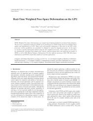
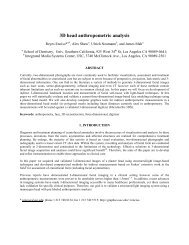
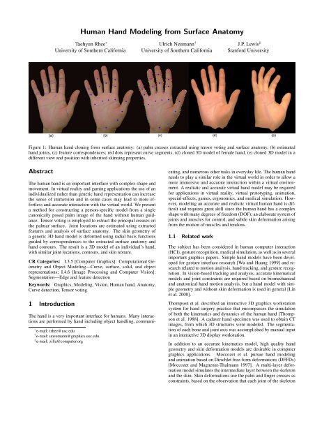
Figure 1: <strong>Human</strong> hand cloning <strong>from</strong> surface anatomy: (a) palm creases extracted using tensor voting and surface anatomy, (b) estimated<br />
hand joints, (c) feature correspondences; red dots represent curve segments, (d) cloned 3D model <strong>of</strong> female hand, (e) cloned 3D model in a<br />
different view and position with inherited skinning properties.<br />
Abstract<br />
The human hand is an important interface with complex shape and<br />
movement. In virtual reality and gaming applications the use <strong>of</strong> an<br />
individualized rather than generic hand representation can increase<br />
the sense <strong>of</strong> immersion and in some cases may lead to more effortless<br />
and accurate interaction with the virtual world. We present<br />
a method for constructing a person-specific model <strong>from</strong> a single<br />
canonically posed palm image <strong>of</strong> the hand without human guidance.<br />
Tensor voting is employed to extract the principal creases on<br />
the palmar surface. Joint locations are estimated using extracted<br />
features and analysis <strong>of</strong> surface anatomy. The skin geometry <strong>of</strong><br />
a generic 3D hand model is deformed using radial basis functions<br />
guided by correspondences to the extracted surface anatomy and<br />
hand contours. The result is a 3D model <strong>of</strong> an individual’s hand,<br />
with similar joint locations, contours, and skin texture.<br />
CR Categories: I.3.5 [Computer Graphics]: Computational Geometry<br />
and Object <strong>Modeling</strong>—Curve, surface, solid, and object<br />
representations; I.4.6 [Image Processing and Computer Vision]:<br />
Segmentation—Edge and feature detection<br />
Keywords: Graphics, <strong>Modeling</strong>, Vision, <strong>Human</strong> hand, <strong>Anatomy</strong>,<br />
Curve detection, Tensor voting<br />
1 Introduction<br />
The hand is a very important interface for humans. Many interactions<br />
are performed by hand including object handling, communi-<br />
∗ e-mail: trhee@usc.edu<br />
† e-mail: uneumann@graphics.usc.edu<br />
‡ e-mail: zilla@computer.org<br />
cating, and numerous other tasks in everyday life. The human hand<br />
needs to play a similar role in the virtual world in order to allow a<br />
more immersive and accurate interaction within a virtual environment.<br />
A realistic and accurate virtual hand model may be required<br />
for applications in virtual reality, virtual prototyping, animation,<br />
special-effects, games, ergonomics, and medical simulation. However,<br />
modeling an accurate and realistic virtual human hand is difficult<br />
and requires great skill since the human hand has a complex<br />
shape with many degrees <strong>of</strong> freedom (DOF); an elaborate system <strong>of</strong><br />
joints and muscles for control, and subtle skin deformation arising<br />
<strong>from</strong> the motion <strong>of</strong> muscles and tendons.<br />
1.1 Related work<br />
The subject has been considered in human computer interaction<br />
(HCI), gesture recognition, medical simulation, as well as in several<br />
important graphics papers. Simple hand models have been developed<br />
for gesture interface research [Wu and Huang 1999] and research<br />
related to motion analysis, hand tracking, and gesture recognition.<br />
In vision-based tracking and analysis, accurate kinematical<br />
models and joint constraints are required based on biomechanical<br />
and anatomical hand motion analysis, but a hand model with simple<br />
geometry and without skin deformation is used in general [Lin<br />
et al. 2000].<br />
Thompson et al. described an interactive 3D graphics workstation<br />
system for hand surgery practice that encompasses the simulation<br />
<strong>of</strong> both the kinematics and dynamics <strong>of</strong> the human hand [Thompson<br />
et al. 1988]. A cadaver hand specimen was used to obtain CT<br />
images, <strong>from</strong> which 3D structures were modeled. The segmentation<br />
<strong>of</strong> each bone and joint axis was accomplished by manual input<br />
in an interactive 3D display workstation.<br />
In addition to an accurate kinematics model, high quality hand<br />
geometry and skin deformation models are desirable in computer<br />
graphics applications. Moccozet et al. pursue hand modeling<br />
and animation based on Dirichlet free-form deformations (DFFDs)<br />
[Moccozet and Magnenat-Thalmann 1997]. A multi-layer deformation<br />
model simulates the intermediate layer between the skeleton<br />
and the skin. Skin deformations use the palm and finger creases as<br />
constraints, based on the observation that each joint <strong>of</strong> the skeleton
ACM SIGGRAPH Symposium on Interactive 3D Graphics and Games I3D 2006<br />
is associated with a hand crease on the surface. However, in their<br />
paper, the creases were determined and designed manually.<br />
Kry et al. use a finite element model (FEM) <strong>of</strong> the human hand<br />
to obtain models in an example-based approach. The models are<br />
then compressed using principal component analysis, and realtime<br />
deformation is demonstrated using GPU acceleration. [Kry et al.<br />
2002].<br />
Albrecht et al. developed a human hand model with its underlying<br />
anatomical structure: skin, muscles, and bones [Albrecht et al.<br />
2003]. <strong>Hand</strong> animation employs a hybrid muscle model. Pseudo<br />
muscles control the rotation <strong>of</strong> bones based on anatomical analysis<br />
and mechanics. Geometric muscles control the deformation <strong>of</strong> the<br />
skin using a mass-spring system. The hand skin geometry is based<br />
on a 3D scanner and the bone-joint structure is obtained <strong>from</strong> a<br />
public 3D skeleton model. Anatomical analysis and physical models<br />
achieve accurate finger movements and skin deformations.<br />
In [Kurihara and Miyata 2004] an example-based deformable human<br />
hand model is derived <strong>from</strong> medical images. Multiple CT<br />
scans <strong>of</strong> the hand are taken in several poses. A comparison <strong>of</strong> bone<br />
shapes and different poses allows the estimation <strong>of</strong> joint locations.<br />
<strong>Hand</strong> skin deformation is achieved using the weighted pose space<br />
deformation (PSD) method.<br />
Tsang et al. describe an anatomically accurate skeletal musculotendon<br />
model <strong>of</strong> human hand. The hand skeleton can be moved using<br />
muscle activations which derive forward and inverse dynamics simulation<br />
[Tsang et al. 2005].<br />
Determination <strong>of</strong> realistic hand poses for interacting with other objects<br />
is also a challenging research topic in computer graphics and<br />
robotics. Several papers suggest interesting solutions for this issue<br />
[Huang et al. 1995; Kim et al. 2000; ElKoura and Singh 2003;<br />
Pollard and Zordan 2005].<br />
It may be noted that the general approach <strong>of</strong> deforming a generic<br />
prior model to match individual shape data has been successfully<br />
applied to heads [Kähler et al. 2002] and the whole body [Allen<br />
et al. 2003; Seo et al. 2003], and that problem domain knowledge<br />
was usefully applied in each <strong>of</strong> these cases.<br />
1.2 Motivations<br />
Virtual reality, simulation, and entertainment applications <strong>of</strong>ten display<br />
a proxy <strong>of</strong> the operator’s hand in the virtual world. The virtual<br />
hand may be driven by camera tracking, a haptic interface, or a sensor/actuator<br />
globe, and serves to provide visual feedback on object<br />
interaction as well as enhancing realism. The operator is intended<br />
to regard this virtual hand as their hand for the purpose <strong>of</strong> interacting<br />
in the virtual world. Differences in shape and mechanics between<br />
the operators’ real and virtual hands may therefore cause inaccuracies<br />
in simulations and decrease the sense <strong>of</strong> immersiveness.<br />
Unfortunately, due to the difficulty, time, and cost <strong>of</strong> generating a<br />
person-specific hand model, immersive systems today generally use<br />
only a simple generic hand model.<br />
Our goal is to make a realistic person-specific 3D virtual hand<br />
model, including skin geometry, texture, and the underlying skeleton.<br />
Our process requires minimal human guidance and depends<br />
only on capturing a skin texture image whose viewing direction is<br />
perpendicular to the palm plane. By analysis <strong>of</strong> the skin texture<br />
<strong>of</strong> the hand, we extract surface anatomy information and estimate<br />
osseous structure underneath the skin.<br />
Our work is most similar to that in [Albrecht et al. 2003], which<br />
employs an image-based hand deformation method to generate individual<br />
hand models. Their method uses an image and scattered<br />
2<br />
interpolation to deform a generic hand model, but it requires manually<br />
defined correspondences between 3D feature points and the<br />
hand image. Furthermore, the limited numbers <strong>of</strong> feature correspondences<br />
are not enough to generate a completely accurate shape<br />
match between the source picture and the final 3D hand model. We<br />
improve upon their efforts in several ways described next.<br />
1.3 Overview and Contributions<br />
We present an automated method to make a specific human hand<br />
model <strong>from</strong> an image <strong>of</strong> the surface anatomy <strong>of</strong> a human hand. The<br />
method has two main parts.<br />
The first part is a surface anatomy feature-extraction method, based<br />
on tensor voting, to extract the main creases on the palmar skin<br />
and the hand geometry without human guidance. Joint structure is<br />
estimated <strong>from</strong> an anatomical analysis <strong>of</strong> the relationships between<br />
the surface anatomy and its osseous structure.<br />
The second part deforms a predefined generic 3D hand model using<br />
scattered data interpolation based on a radial basis functions<br />
(RBFs). A curve segment matching method performs automatic<br />
feature correspondences between the 3D hand model and the contours<br />
detected in the hand image. These matches capture the contour<br />
<strong>of</strong> the hand image as well as the geometry <strong>of</strong> joints, finger tips<br />
and finger valleys.<br />
As our contribution is the modeling <strong>of</strong> person-specific 3D hand geometry,<br />
issues such as animation <strong>of</strong> skin deformation, texture capture,<br />
and texture blending are beyond the scope <strong>of</strong> the paper, and<br />
we rely on existing techniques for these problems. Our generic<br />
model is manually generated using Maya, and the person-specific<br />
hand inherits the skin deformation system <strong>of</strong> the generic hand. Alternatively<br />
sophisticated automated techniques for animated skin<br />
deformation such as [Kurihara and Miyata 2004; Kry et al. 2002]<br />
could be adapted.<br />
We texture mapped the hand using planar projection and manually<br />
blended the palm and dorsal textures. However improved texture<br />
blending techniques such as [Burt and Adelson 1983; Zhou et al.<br />
2005] should be considered.<br />
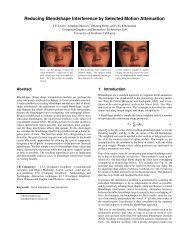
Figure 2: Process overview: Two main parts are grouped into<br />
four steps in the gray boxes. Supplementary parts which need additional<br />
tools or are beyond the scope <strong>of</strong> our work are indicated by the<br />
dotted boxes. Numbers beside each box indicate the required user<br />
interaction level; level 2 is fully automatic, level 1 requires no user<br />
interaction but needs some parameters (experimentally fixed in normal<br />
case; Canny edge thresholds, tensor voting σ, finger extraction<br />
thresholds), level 0 needs manual input.
ACM SIGGRAPH Symposium on Interactive 3D Graphics and Games I3D 2006<br />
As a result, the final hand model has the same joint structure, hand<br />
geometry, contour curves, and texture map as the original hand image.<br />
Our method requires only an image <strong>of</strong> a hand and requires no<br />
manual input. Figure 2 describes our methods and user interaction<br />
level in each step. The details are covered in the remainder <strong>of</strong> the<br />
paper.<br />
2 <strong>Hand</strong> anatomy<br />
The human hand has a complex anatomical structure consisting <strong>of</strong><br />
bones, muscles, tendons, skin, and the complex relationships between<br />
them [Brand and Hollister 1999; Kry et al. 2002]. Analysis<br />
<strong>of</strong> human hand anatomical structures is important in various fields,<br />
including ergonomics, HCI, hand surgery, as well as computer animation.<br />
The bones <strong>of</strong> the hand are grouped into three areas: digital, carpal,<br />
and wrist. The digital bones <strong>of</strong> four fingers consist <strong>of</strong> distal, middle,<br />
and proximal phalanges with distal interphalangeal (DIP), proximal<br />
interphalangeal (PIP), and metacarpal phalangeal (MCP) joints.<br />
The digital bones <strong>of</strong> the thumb consist <strong>of</strong> the distal and proximal<br />
phalange with the interphalangeal (IP) and carpometacarpal (CMC)<br />
joints. The carpal bones are a set <strong>of</strong> eight small bones, and the wrist<br />
bones are the radius and ulna [Figure 3(a)].<br />
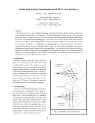
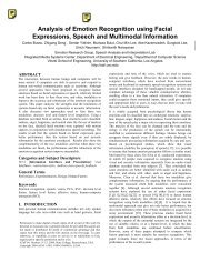
Figure 3: <strong>Human</strong> hand anatomy: (a) Bone <strong>Anatomy</strong> 1. Distal<br />
phalanx, 2. Middle phalanx, 3. Proximal phalanx, 4. Metacarpals,<br />
5. Ulna, 6. Radius, A. DIP joint, B. PIP joint, C. MCP joint, D.<br />
IP joint, E. CMC joint; (b) <strong>Surface</strong> <strong>Anatomy</strong> 1. Distal phalanx,<br />
2. Middle phalanx, 3. Proximal phalanx, 4. Distal palmar, A. DIP<br />
crease, B. PIP crease, C. Palmar digital crease, D. Distal palmar<br />
crease, E. Proximal palmar crease, F. Thenar crease, G. Distal wrist<br />
crease, F1-5. Thumb, Index, Middle, Ring, Little finger.<br />
In biomechanics, not only the anatomical features but also the mechanical<br />
joints <strong>of</strong> the hand are important. Several methods are<br />
suggested to define the mechanical joints. In [Brand and Hollister<br />
1999; Kurihara and Miyata 2004], the axis <strong>of</strong> rotation between two<br />
bones is defined as a line that does not move in relationship with<br />
either bone while the bones move around each other. On the other<br />
hand, the mechanical joint centers <strong>of</strong> the hand have been anatomically<br />
estimated as the center <strong>of</strong> curvature <strong>of</strong> the head <strong>of</strong> the bone<br />
proximal to the given joint [Buchholz et al. 1992; Youm et al. 1978].<br />
Figure 3(b) shows the basic surface anatomy <strong>of</strong> the human hand<br />
[Yu et al. 2004]. The three palmar skin regions are the palm, fingers,<br />
and thumb. The palm region has three main creases. The proximal<br />
palmar crease starts <strong>from</strong> the silhouette edge <strong>of</strong> the hand near the<br />
head <strong>of</strong> the metacarpal bone <strong>of</strong> the index finger and runs through<br />
the hollow <strong>of</strong> the palm. The distal palmar crease starts <strong>from</strong> the<br />
head <strong>of</strong> the metacarpal bone in the little finger and runs through<br />
the hollow, passing the head <strong>of</strong> the metacarpal bone <strong>of</strong> the ring and<br />
3<br />
middle finger. The thenar crease is located between the proximal<br />
palmar crease and distal wrist crease longitudinally.<br />
The fingers have three transverse digital creases, the DIP, PIP, and<br />
palmar digital crease. A DIP crease and palmar digital crease are<br />
located on the thumb. The distal palm area is located between the<br />
line, which starts <strong>from</strong> the radial end <strong>of</strong> the proximal palmar crease<br />
to the ulnar end <strong>of</strong> the distal palmar crease and the palmar digital<br />
creases. The MCP joints <strong>of</strong> fingers are located in the distal palm<br />
area.<br />
Since the crease on the palmar skin is produced by a skin flexion<br />
fold when the hand is closed, basic creases on the palmar skin have<br />
a strong relationship with the underlying bone structure, resulting<br />
in landmarks used in hand surgery [Brand and Hollister 1999; Yu<br />
et al. 2004]. Bugbee et al. demonstrated the relationship between<br />
creases <strong>of</strong> palmar skin and superimposed osseous anatomy using<br />
radiograph [Bugbee and Botte 1993]. Since most skin creases <strong>of</strong><br />
the palmar skin are consistent with underlying fascia and located<br />
near the center <strong>of</strong> the curvature <strong>of</strong> the head <strong>of</strong> the bone proximal<br />
<strong>of</strong> the given joint, we observe that the creases can be used as an<br />
estimation <strong>of</strong> mechanical joints when folding the human hand.<br />
The surface anatomy <strong>of</strong> the hand, as well as the bone structure, is<br />
unique for an individual human hand [Yu et al. 2004]. Due to their<br />
uniqueness, hand surface features have been proposed for biometric<br />
use. For example, a palm print has three principal lines (distal<br />
palmar, proximal palmar, and thenar creases) that are unique and<br />
unchanging biometrics suitable to identify a person [Shu and Zhang<br />
1998; Jain et al. 1999]. Also, palmistry uses these lines to indicate<br />
individual characteristics.<br />
3 Basic hand geometry extraction<br />
In this paper, we define basic hand geometry as the contour <strong>of</strong> the<br />
hand, finger tips, and finger “ valleys ” shown in Figure 4(b). Since<br />
we use skin texture as the base hand image, it is generally taken<br />
within good lighting conditions, simple dark background, fingersextended<br />
natural pose, and fixed camera location. The camera viewing<br />
direction is perpendicular to the palm plane and the image up<br />
vector is on the axis <strong>from</strong> wrist joint to middle finger tip. We assume<br />
an orthographic camera and explain our method based on the<br />
right hand due to the similarity and symmetry <strong>of</strong> the left and right<br />
hand.<br />
Generally, contour extraction is a similar problem as background<br />
extraction in computer vision. In our case, since we used a specified<br />
background, a simple Canny edge algorithm [Forsyth and Ponce<br />
2002] followed by a binary image thresholding is enough to extract<br />
a proper contour line [Figure 4(b)]. When we see the surface<br />
anatomy <strong>of</strong> each finger, their shapes are almost symmetrical and<br />
each finger tip is located on the intersection between the medial axis<br />
curve <strong>of</strong> each finger and the hand contour curve. Since our canonical<br />
photograph pose has the fingers oriented upward, we can easily<br />
locate the finger extremities by scanning the medial axis curves in<br />
the y-direction. When we sort the fingers with respect to x-axis, we<br />
can easily identify the finger tips for each finger. The finger valleys<br />
are located in between each finger. We trace a contour curve <strong>from</strong><br />
each finger tip and define each finger valley as the inflection point<br />
<strong>of</strong> that curve.<br />
4 <strong>Hand</strong> crease extraction<br />
The palmar skin has complex geometry with lots <strong>of</strong> discontinuous<br />
wrinkles. Among the wrinkles, just a few salient creases are meaningful<br />
in terms <strong>of</strong> surface anatomy. Although humans can easily
ACM SIGGRAPH Symposium on Interactive 3D Graphics and Games I3D 2006<br />
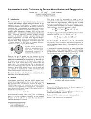
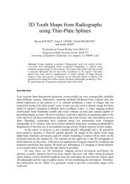
Figure 4: Palm creases extraction process: (a) Segmented hand image, (b) Basic hand geometry; contour <strong>of</strong> the hand, five finger tips, four<br />
finger valleys, and medial axis <strong>of</strong> each finger, (c) Sobel edge image, (d) First tensor voting result, (e) Second tensor voting result (final result)<br />
detect these creases, computers can hardly detect them without human<br />
visual perception. Tensor voting [Guy and Medioni 1996] is<br />
an efficient perceptual grouping framework to detect dense salient<br />
features in noisy input data. We use the tensor voting framework<br />
[Medioni et al. 2000; IRIS] to detect principal creases and extract<br />
continuous curves for each crease in the palmar skin image.<br />
4.1 Tensor voting overview<br />
Extracting main creases <strong>from</strong> the palmar skin is a similar problem<br />
to inferring salient curves <strong>from</strong> sparse and noisy data. Tensor voting<br />
can extract salient geometric features (e.g. point, curve, surface)<br />
in a sparse and noisy data set without human guidance. The tensor<br />
voting framework proposed in [Medioni et al. 2000] needs only one<br />
free parameter σ to define the scale <strong>of</strong> the vote, and handles multidimensional<br />
data as well as 2D data for various applications. Tensor<br />
voting can be grouped into two major stages: data encoding using<br />
tensors and linear tensor voting for tensor communication. The input<br />
tokens, a set <strong>of</strong> points or oriented points in a noisy environment,<br />
can be encoded into a set <strong>of</strong> geometric features which are salient,<br />
smooth and considerably continuous.<br />
In the case <strong>of</strong> 2D, each token can be encoded into a second order<br />
symmetric tensor which is equivalent to an ellipse whose major axis<br />
serves as the orientation and the length <strong>of</strong> that axis is the saliency.<br />
In Figure 5(a), an oriented point is represented by a thin oriented<br />
ellipse. In the voting stage, each token is accumulated into the second<br />
order symmetric tensor form by votes cast <strong>from</strong> its neighbors’<br />
predefined voting fields. The voting field <strong>of</strong> oriented tokens can be<br />
derived <strong>from</strong> the 2D stick tensor (degenerate ellipse with λ2 = 0)<br />
called the fundamental 2D stick kernel, and it decays the saliency <strong>of</strong><br />
the vote. In spherical coordinates, the decay <strong>of</strong> the 2D stick kernel<br />
is <strong>of</strong> the form:<br />
DF(γ, θ, σ) = e −( γ2 +cθ 2 )<br />
σ 2 (1)<br />
Where, γ is the arc length between voter and receiver, θ is the curvature<br />
between voter and receiver, σ is the scale <strong>of</strong> voting which<br />
defines the size <strong>of</strong> the neighborhood <strong>of</strong> each token, and c is a constant.<br />
In the Figure 5(b), the osculating circle connecting voter O<br />
and receiver P generates the smoothest circular path connecting O<br />
and P, and the length <strong>of</strong> normal vector P represents the saliency <strong>of</strong><br />
the vote. After voting, the second order symmetric tensor T can be<br />
decomposed into its eigenvectors e1, e2 with related eigenvalue λ1<br />
≥ λ2.<br />
<br />
λ1 0<br />
<br />
e1<br />
T = [e1,e2]<br />
0 λ2<br />
T<br />
e2 T<br />
<br />
= λ1e1e T 1 + λ2e2e T 2<br />
Equation 2 can be rearranged with Tc, which represents curve component,<br />
and Tp, which represents point component encoding junction<br />
information.<br />
(2)<br />
4<br />
T = (λ1 − λ2)e1e T 1 + λ2(e1e T 1 + e2e T 2 ) = Tc + Tp<br />
As a result <strong>of</strong> voting in 2D space, we have two dense vector maps<br />
which represent curve and junction features. The salient curves are<br />
located at the local extrema <strong>of</strong> map Tc, and they can be extracted<br />
using non-maxima suppression. Please refer to [Guy and Medioni<br />
1996; Medioni et al. 2000] for details.<br />
Figure 5: Tensor Voting: (a) tensor ellipse, (b) 2D stick kernel, (c)<br />
Tensor voting example: left image shows the sparse input tokens<br />
without orientation, middle image is the tokens oriented by tensor<br />
voting but still sparse, the right image is the resulting extracted<br />
dense curve.<br />
4.2 Wrinkle extraction using tensor voting<br />
In order to increase the performance <strong>of</strong> tensor voting, we segment<br />
the hand image. From the hand geometry extracted in section 3, we<br />
can roughly divide hand images into three regions; the palm, thumb,<br />
and four fingers. In the four fingers and thumb region, the medial<br />
axis for each fingers and thumb are calculated. For all pixels in<br />
the four fingers and thumb region, find the nearest medial axis line.<br />
The region which is related to the nearest line <strong>of</strong> the given pixel is<br />
assigned to the region for that pixel. Finally we achieve six image<br />
segments, like Figure 4(a). The image segments are converted into<br />
the set <strong>of</strong> edge points using the Sobel edge algorithm [Forsyth and<br />
Ponce 2002]. Although the Canny edge algorithm is generally used<br />
for edge detection, the Sobel edge algorithm shows better performance<br />
as an input <strong>of</strong> tensor voting in our experiment [Figure 4(c)].<br />
Since the only free variable σ is not sensitive, we experimentally<br />
define the voting scale σ as large as possible to reduce the influence<br />
<strong>of</strong> local features which can produce noise. The result <strong>of</strong> first tensor<br />
voting is in Figure 4(d). In order to eliminate small noises and<br />
achieve smoother curves, we perform a second tensor voting using<br />
the input <strong>of</strong> the first tensor voting results. In the second voting<br />
stage, the outline <strong>of</strong> the fingers which are generated by the first<br />
tensor voting is eliminated before voting, since the contour line is<br />
salient and can cause errors in the voting process. The final result<br />
(3)
ACM SIGGRAPH Symposium on Interactive 3D Graphics and Games I3D 2006<br />
<strong>of</strong> tensor voting is the set <strong>of</strong> salient wrinkle curves and each curve<br />
is smooth and mostly continuous [Figure 4(e)].<br />
4.3 Palm crease extraction<br />
Now we have images <strong>of</strong> continuous principal wrinkles <strong>of</strong> the palm<br />
and each <strong>of</strong> the fingers but they do not yet correspond to the important<br />
creases <strong>of</strong> surface anatomy. In the palm region, we have<br />
three anatomically meaningful creases, the distal palmar, proximal<br />
palmar, and thenar crease [Figure 3]. Since the wrinkle curves<br />
achieved <strong>from</strong> tensor voting are continuous and have longer length<br />
than other curves, we can extract these creases using a tree search<br />
algorithm that employs knowledge <strong>of</strong> hand geometry.<br />
Variables: R=region, r=start point, W=wrinkle, P=path,<br />
L=path length<br />
1 Define region R using basic hand geometry [Section 3];<br />
2 Scan R finding start points ri <strong>of</strong> wrinkle curve Wi;<br />
/* Where ri = {r1,...,rn},Wi = {W1,...,Wn},ri ∈ R*/;<br />
3 for all ri do<br />
4 while Traverse curve <strong>from</strong> ri to the end using DFS do<br />
5 if found the largest path Pi then<br />
6 Wi ←− Pi; Li ←− Length(Pi);<br />
7 if IsMaximum(Li) then<br />
8 Crease C ←− Wi;<br />
9 Repeat step 1 to 8 for each anatomical region R;<br />
Algorithm 1: Palm crease extraction algorithm<br />
First, we assign anatomical region R to find the starting point <strong>of</strong> the<br />
crease. For example, the root <strong>of</strong> the distal palmar crease can be located<br />
in region Rd(Rd ∈ R) in Figure 9(a) (Color Plate). The region<br />
Rd can be defined easily using hand geometry features such as finger<br />
valley 4 and the MCP joint <strong>of</strong> thumb. The MCP joint <strong>of</strong> thumb<br />
can be roughly estimated using the finger line <strong>of</strong> thumb and finger<br />
valley 1. The region for the root <strong>of</strong> the proximal palmar crease can<br />
be assigned by similar anatomical analysis. Since the start points<br />
<strong>of</strong> several wrinkle curves can be in the region R, we should find<br />
the main crease among these wrinkle curves. First, we extract every<br />
wrinkle curve and its arc length using depth first search (DFS),<br />
since our wrinkle curve has no loops. For every start point ri (ri ∈<br />
region R), traverse wrinkle curve using DFS and assign the largest<br />
path Pi as the wrinkle curve Wi having length Li. The wrinkle<br />
curve Wi which has the largest length among Li is assigned to the<br />
crease C within the area R. We summarize the method in Algorithm<br />
1. Green curves in the Figure 9(a) (Color Plate) are the extracted<br />
proximal palmar crease and the distal palmar crease.<br />
4.4 Finger crease extraction<br />
We propose a method to extract the crease <strong>of</strong> each finger <strong>from</strong> the<br />
given wrinkle images. First, label in turn each segmented image<br />
in section 4.2 as finger region Ri, (i for each finger). Then, assign<br />
finger line Fi using the least square line fit <strong>of</strong> the medial axis curve<br />
<strong>of</strong> each finger region Ri (calculated in section 3). For each finger,<br />
perform the following operations in Algorithm 2 to extract representative<br />
lines <strong>of</strong> finger creases. The result is in Figure 9(b) (Color<br />
Plate).<br />
5 <strong>Hand</strong> modeling<br />
We made a generic 3D hand model [Figure 6(c),(e)] which has skin<br />
geometry, joint skeleton, and skin deformation using Maya [Alias]<br />
5<br />
Variables: R: finger region, F: finger line, p: current position,<br />
W: wrinkle curves, O: orthogonal line(F, p), O’:<br />
Selected lines, C: Selected crease line, threshold1<br />
and threshold2 are defined after experiment.<br />
1 for each finger region Ri and line Fi do<br />
2 while Trace Fi <strong>from</strong> finger tips to wrist using pi do<br />
/* pi(1 ≤ i ≤ 5, pi ∈ Ri) is a current tracing position<br />
*/;<br />
3 if pi is an intersection point between<br />
Fi and Wik = {Wi1,...,Win} then<br />
4 Calculate a line Oik = {Oi1,...,Oin}, which is<br />
orthogonal to Fi and passes through the intersection<br />
point;<br />
5 for all pixels Xi ∈ creases <strong>of</strong> Ri do<br />
6 if |Xi − Oik| < threshold1 then<br />
vote(Oik);<br />
7 if vote(Oik) > threshold2 then<br />
O ′ ik ←− Oik, where O ′ ik = {O′ i1 ,...,O′ im };<br />
8 if O ′ ik is verified by the hand geometry such as finger<br />
region, tips, and valleys then<br />
Cik ←− O ′ ik , where Cik = {Ci1,...,CiN};<br />
Algorithm 2: Finger crease extraction algorithm<br />
and Poser [CuriousLab]. The skin geometry is exported <strong>from</strong> Poser<br />
and bound to the joint skeleton using Maya for skin deformation<br />
and convenient joint control. The joint skeleton has accurate biomechanical<br />
structure using 21 joints (including finger tips and wrist)<br />
[Figure 6(e)].<br />
Each joint has a different degree <strong>of</strong> freedom for better control. Although<br />
carpal and wrist bones consist <strong>of</strong> several bone segments,<br />
since the radio carpal joint plays the most important part <strong>of</strong> overall<br />
movement, we defined one three-DOF mechanical joint for the<br />
wrist joint. DIP and PIP joints <strong>of</strong> each finger and the IP and MCP<br />
joints <strong>of</strong> thumb have one DOF. MCP joints <strong>of</strong> each finger have two<br />
DOF for the simplicity <strong>of</strong> control and the CMC joint <strong>of</strong> the thumb<br />
has three DOF due to its complexity. For simple notation, we will<br />
call the generic 3D hand model a generic hand, the 2D hand features<br />
extracted <strong>from</strong> the picture a source hand, and the remodeled<br />
3D hand model a clone hand. The generic 3D hand model is reshaped<br />
as a clone hand that has the same mechanical joints, contour<br />
curve, and texture map as the unique human hand.<br />
5.1 Joint modeling<br />
From the careful analysis <strong>of</strong> hand surface anatomy (consisting <strong>of</strong><br />
the basic hand geometry and creases extracted in the previous section),<br />
we can estimate mechanical joint locations <strong>of</strong> the source<br />
hand. From the finger crease lines Cin and finger lines Fi obtained<br />
in section 4.4., we can find DIP and PIP joints <strong>of</strong> the four fingers<br />
and the IP and MCP joints <strong>of</strong> the thumb. Since the finger lines are<br />
the medial axis, the mechanical joints are located on the intersection<br />
points between the crease lines Cin and finger lines Fi. If two<br />
creases are extracted near a joint, we locate the joint at the lower<br />
crease with the analysis <strong>of</strong> surface anatomy.<br />
When we consider smooth skin deformation with crease constraints,<br />
MCP joints <strong>of</strong> the the four fingers should be located in<br />
the distal palm area [Figure 9(c) (Color Plate)]. From each finger<br />
line Fi we can calculate line segment Si, which is between the related<br />
digital crease and the line H, which is defined by start points
ACM SIGGRAPH Symposium on Interactive 3D Graphics and Games I3D 2006<br />
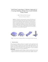
Figure 6: <strong>Hand</strong> clone results: (a) picture <strong>of</strong> source hand, (b) clone<br />
hand model with texture mapping, (c) skin geometry <strong>of</strong> generic<br />
hand model, (d) deformed skin geometry <strong>of</strong> clone hand, (e) joint<br />
skeleton <strong>of</strong> generic hand model (each circle is a joint location), (f)<br />
modified joint skeleton <strong>of</strong> clone hand<br />
<strong>of</strong> distal palmar crease Ha and the start point <strong>of</strong> proximal palmar<br />
crease Hb [Figure 9(c) (Color Plate)]. Within each segment Si, we<br />
can arrange MCP joints at approximately one-third <strong>of</strong> Si <strong>from</strong> the<br />
line H with the analysis <strong>of</strong> surface anatomy in section 2.<br />
The two highest curvature points, Wa and Wb <strong>of</strong> the ulnar and radial<br />
side <strong>of</strong> contour curve in wrist area, can represent the anatomical<br />
boundary between the wrist bones (ulna and radius) and carpal<br />
bones. These two points, Wa and Wb, are simply calculated by the<br />
highest curvature points <strong>of</strong> contour within the wrist region, which is<br />
below the MCP joint <strong>of</strong> the thumb. The wrist joint can be estimated<br />
by mid-position <strong>of</strong> Wa and Wb [Figure 9(c) (Color Plate)].<br />
We have extracted every mechanical joint except the thumb CMC<br />
joint with analysis <strong>of</strong> surface anatomy. However, since the CMC<br />
joint <strong>of</strong> the thumb has relatively complex movements compared<br />
with other joints, and 2D surface anatomy cannot give enough information,<br />
estimating the CMC joint is very difficult. We position<br />
the thumb CMC joint based on the following anatomical analysis.<br />
First, the metacarpal bone <strong>of</strong> the thumb is parallel to line M and<br />
starts <strong>from</strong> the MCP joint <strong>of</strong> thumb [Figure 9(c) (Color Plate)]. Line<br />
M can be calculated by least square line fitting on the middle part <strong>of</strong><br />
contour curve segment between the highest curvature point Wb and<br />
the MCP joint. The axis <strong>of</strong> the radius bone is parallel to the medial<br />
axis <strong>of</strong> wrist and passes point Wb. Since the anatomical CMC joint<br />
6<br />
is located on the end <strong>of</strong> the metacarpal bone, the mechanical CMC<br />
joint can be on the intersection point between the axis <strong>of</strong> the radius<br />
bone and metacarpal bone.<br />
From the extracted 2D joints, we can modify the joint skeleton <strong>of</strong><br />
the 3D generic hand. Since the origin and the y-axis <strong>of</strong> the generic<br />
hand model is determined by the wrist joint and the vector <strong>from</strong><br />
wrist joint to middle finger tip, respectively, a simple affine transformation<br />
matrix Ms can transfer the source hand coordinate to the<br />
generic hand coordinate. For accurate scaling, we measured hand<br />
length <strong>from</strong> the wrist to the middle finger tip when taking the hand<br />
picture. The generated joint skeleton model for clone hand is shown<br />
in Figure 6(f).<br />
5.2 Skin modeling<br />
In addition to the joints, the contour <strong>of</strong> the hand is a unique and<br />
important feature <strong>of</strong> a person’s hand. Curve segment matching can<br />
allow automatic feature correspondence between the source hand<br />
and generic hand. From the corresponding features we can warp<br />
entire geometry using scattered data interpolation based on the radial<br />
basis functions (RBFs).<br />
5.2.1 Curve segment matching<br />
From the joint modeling process in section 5.1, we can obtain a<br />
joint skeleton model with 21 corresponding features. The skin vertices<br />
related to the joint skeleton can be used as the corresponding<br />
feature between the generic and source hand. In addition to these<br />
21 features, contour <strong>of</strong> the hand provides good feature correspondences,<br />
since the source hand picture is also a skin texture image<br />
taken in the specific viewing direction and pose [Figure 6(a)].<br />
When we deform the hand skin, the mesh between creases should<br />
be continuous. The contour <strong>of</strong> the hand can be divided into 30<br />
curve segments Gi = {G1,...,G30} based on the hand creases and<br />
geometry <strong>from</strong> the analysis <strong>of</strong> hand surface anatomy [Figure 1(c)];<br />
each Gi consists <strong>of</strong> ordered 3D vertices Vij = {Vi1,...,Vin} along<br />
the curve segment Gi, where n is chosen to represent curve segment<br />
geometry sufficiently and Gi are carefully extracted when making a<br />
generic hand model using the related joint skeleton.<br />
Figure 7: Curve segment matching example: (a) Curve matching<br />
example <strong>of</strong> curve segment S2(s2,e2): s2 is on the intersection between<br />
contour and the palmar distal crease <strong>of</strong> little finger, and the<br />
e2 is on the intersection between contour and the PIP crease <strong>of</strong> little<br />
finger, (b) Curve segment 2 in generic hand model<br />
Every Gi is transformed to the source hand coordinate using the<br />
inverse matrix <strong>of</strong> Ms in section 5.1. The transformed curve segments<br />
are G ′ i = {G′ 1 ,...,G′ 30 } and each segment G′ i consists <strong>of</strong> transformed<br />
2D points V ′ ij . With curve segment matching based on the<br />
arc length, we can find corresponding feature <strong>of</strong> V ′ ij in the source<br />
hand image. Our algorithm can accumulate small errors within its<br />
traversing step but it shows acceptable results in our experiment.
ACM SIGGRAPH Symposium on Interactive 3D Graphics and Games I3D 2006<br />
The method is described in Algorithm 3 and an example <strong>of</strong> curve<br />
segment 2 is in Figure 7.<br />
Variables: G: curve segments <strong>of</strong> the generic hand, G’: transformed<br />
curve segments <strong>of</strong> the generic hand, S:<br />
curve segments <strong>of</strong> the source hand, V’: transformed<br />
vertices composing a curve segment G’<br />
1 Define curve segment Si(si,ei) = {S1,...,S30} <strong>from</strong> hand<br />
anatomy [Figure 1(c)];<br />
/* si: start point <strong>of</strong> segment, ei: end point <strong>of</strong> segment */;<br />
/* Each G ′ i correspond with segment Si using its anatomical<br />
location */;<br />
2 Calculate arc length <strong>of</strong> G ′ i and Si;<br />
3 Calculate scaling γ = length(Si)/ length(G ′ i );<br />
4 for all segment i do<br />
5 for all vertices j in segment i, V ′<br />
i, j = {V ′<br />
i,1 ,...,V ′<br />
i,n } do<br />
Calculate D j = |V ′<br />
i, j+1 −V′ i, j | /* n: number <strong>of</strong> vertices<br />
on the G ′ i */;<br />
6 Initialize s ′ j = pk = si; /* s ′ j : current start point, pk :<br />
pixels in the Si */;<br />
7 while traverse pk <strong>from</strong> si to ei do<br />
8 Calculate D ′ j = |pk − s ′ j |;<br />
9 if D ′ j ≥ γD j then<br />
10 Assign pk as the corresponding feature <strong>of</strong> Vi, j+1;<br />
11 s ′ j ←− pk;<br />
Algorithm 3: Curve segment matching algorithm<br />
5.2.2 Skin deformation<br />
With the set <strong>of</strong> point locations xi = {x1,...,xn} and their values fi =<br />
{ f1(x1),..., fn(xn)} we can find function R(x) which gives smooth<br />
interpolation <strong>of</strong> these data using radial basis functions (RBFs) [Carr<br />
et al. 2001].<br />
n<br />
R(x) = P(x) + ∑ λiφ(|x − xi|), x ∈ R<br />
i=1<br />
d<br />
In equation 4, P(x) is a low-degree polynomial, λi is a real valued<br />
weigh, φ is a basis function, and n is the number <strong>of</strong> control<br />
points. Our RBFs R(x) are defined by the corresponding feature<br />
points achieved in section 5.2.1, and its distance vector between<br />
the generic hand and source hand. The thin plate spline (TPS),<br />
φ(r) = r 2 logr is used as our basis function for smooth deformation<br />
<strong>of</strong> our skin mesh, since TPS interpolates specified points while<br />
minimizing an approximate curvature [Bookstein 1989].<br />
The vertices <strong>of</strong> the generic hand mesh are displaced by the RBFs<br />
resulting in a clone hand which has the same contour curve, hand<br />
geometry, and joint location as the source hand. The depth value <strong>of</strong><br />
hand geometry was not considered in RBFs deformation, since the<br />
features for depth could not be obtained <strong>from</strong> the 2D source hand<br />
image. Instead, the generic hand depth is proportionally scaled by<br />
the hand length measured in section 5.1.<br />
6 Results<br />
Our automated method generates a person-specific human hand<br />
model with similar joint structure and skin geometry to the source<br />
individual’s hand. The similarity between the original and cloned<br />
hand can be seen in Figure 6(a) and (b). While texturing and animated<br />
skin deformation are beyond the scope <strong>of</strong> this paper, some<br />
(4)<br />
7<br />
Figure 8: <strong>Hand</strong> clone result in various view points<br />
supplementary properties <strong>of</strong> our process help reduce the effort involved<br />
in these tasks:<br />
• The source hand image can be re-used as the skin texture map<br />
in the 3D clone hand. Due to the similarity <strong>of</strong> contour shape<br />
and scaling between the clone hand and the skin texture, the<br />
texture mapping can be executed using simple planar projection<br />
in the camera direction.<br />
• Also, because our generic hand model has a joint skeleton<br />
bound to skin geometry, it is easy to control the final model using<br />
this joint skeleton [Figure 6(f)]. If the generic hand model<br />
has animated skin deformation or other properties, the clone<br />
hand inherits those characteristics properly.<br />
These supplementary properties are demonstrated in Figure 8, and<br />
Figure 1(e) where the individualized model is textured by planar<br />
projection, and the skin deformation system <strong>from</strong> the underlying<br />
generic Maya hand model is used to deform the skin guided by<br />
rotations <strong>of</strong> the skeleton joints.<br />
We tested our method by creating five human hand models having<br />
different age, sex, and scale; a four year-old girl, a five year-old<br />
boy, a large male, an average female, and an average male. We took<br />
hand picture in specific conditions described in section 3 and used<br />
two generic hand models, a low resolution mesh (13372 triangles<br />
with 6715 vertices), and a high resolution mesh (32784 triangles<br />
with 16423 vertices). The results are shown in Figure 10 (Color<br />
Plate). The first row shows extracted joint information, the second<br />
row shows rendered clone model with texture maps, the third row<br />
shows the polygon mesh, and each column demonstrates cloning a<br />
particular source hand.<br />
Our method requires setting several thresholds to extract creases;<br />
Canny edge detection, tensor voting, and crease extraction. Once
ACM SIGGRAPH Symposium on Interactive 3D Graphics and Games I3D 2006<br />
set the default thresholds are sufficient during our test provided<br />
good lighting conditions (without significant shadows on surfaces)<br />
in the source image.<br />
7 Conclusions<br />
In this paper, we presented a method to make a person-specific<br />
hand model using the surface anatomy visible in a single photograph<br />
<strong>of</strong> that individual’s hand. We extracted basic hand geometry<br />
and creases using tensor voting for the surface anatomy features.<br />
The joint structure was inferred <strong>from</strong> the surface anatomy features.<br />
Finally, we deformed skin geometry using RBFs with automated<br />
feature correspondences based on the curve segment matching.<br />
As a result, we can create a virtual hand clone that has the same<br />
contour geometry, joint skeleton, and skin texture map as the source<br />
person. Since the algorithm has no human guidance (other than<br />
threshold adjustment in difficult cases) and the only information<br />
required is a palmar skin image, the method is easily applied.<br />
Since we only use a palm picture, we cannot measure hand thickness<br />
accurately, relying instead on an approximate depth proportional<br />
to hand length. This approximation may result in an erroneous<br />
depth <strong>of</strong> the joints within the mesh. Because the CMC joint<br />
<strong>of</strong> the thumb has very complex mechanisms in terms <strong>of</strong> biomechanics<br />
and anatomy, accurate CMC joint modeling <strong>from</strong> a 2D image<br />
cannot be guaranteed.<br />
Also, because our method relies on important creases on the palmar<br />
skin, we cannot apply our algorithms to an atypical human hand; for<br />
example, those with missing or vague important creases, or with<br />
corns, calluses, and any significant scar on the palmar surface.<br />
On the other hand, our overall approach does not prohibit the integration<br />
<strong>of</strong> additional information, such as additional texture photographs<br />
<strong>from</strong> other angles, and accurate depth data <strong>from</strong> a volumetric<br />
scanner.<br />
Acknowledgments<br />
We appreciate Pamela Fox, Zhenyao Mo, Genich Kawada, Changki<br />
Min, and especially Dr. Tiffany Grunwald in USC medical school<br />
for her advice on the anatomy <strong>of</strong> the human hand.<br />
References<br />
ALBRECHT, I., HABER, J., AND SEIDEL, H. P. 2003. Construction and animation<br />
<strong>of</strong> anatomically based human hand models. In Proceedings <strong>of</strong> the 2003 ACM SIG-<br />
GRAPH/Eurographics Symposium on Computer Animation (SCA-03), 98–109.<br />
ALIAS. Maya 6. http://www.alias.com.<br />
ALLEN, B., CURLESS, B., AND POPOVIĆ, Z. 2003. The space <strong>of</strong> human body<br />
shapes: reconstruction and parameterization <strong>from</strong> range scans. ACM Trans. Graph.<br />
22, 3, 587–594.<br />
BOOKSTEIN, F. L. 1989. Principal warps: Thin-plate splines and the decomposition<br />
<strong>of</strong> deformations. IEEE. Trans. Pattern Analysis and Machine Intelligence 11, 567–<br />
585.<br />
BRAND, P. W., AND HOLLISTER, A. M. 1999. Clinical mechanics <strong>of</strong> the hand: 3rd<br />
Ed. Mosby.<br />
BUCHHOLZ, B., ARMSTRONG, T., AND GOLDSTEIN, S. 1992. Anthropometric data<br />
for describing the kinematics <strong>of</strong> the human hand. Ergonomics 35, 3, 261–73.<br />
BUGBEE, W. D., AND BOTTE, M. J. 1993. <strong>Surface</strong> anatomy <strong>of</strong> the hand: The relationships<br />
between palmar skin creases and osseous anatomy. Clinical Orthopaedics<br />
and Related Research, 296, 122–126.<br />
BURT, P., AND ADELSON, E. 1983. A multiresolution spline with application to<br />
image mosaics. ACM Transaction on Graphics 2, 4 (Oct.).<br />
8<br />
CARR, J. C., BEATSON, R. K., CHERRIE, J. B., MITCHELL, T. J., FRIGHT, W. R.,<br />
MCCALLUM, B. C., AND EVANS, T. R. 2001. Reconstruction and representation<br />
<strong>of</strong> 3D objects with radial basis functions. In SIGGRAPH 2001, Computer Graphics<br />
Proceedings, ACM Press / ACM SIGGRAPH, 67–76.<br />
CURIOUSLAB. Poser 5. http://www.curiouslabs.com.<br />
ELKOURA, G., AND SINGH, K. 2003. <strong>Hand</strong>rix: animating the human hand. In<br />
SCA ’03: Proceedings <strong>of</strong> the 2003 ACM SIGGRAPH/Eurographics symposium on<br />
Computer animation, 110–119.<br />
FORSYTH, D., AND PONCE, J. 2002. Computer Vision A Modern Approach. Prentice<br />
Hall.<br />
GUY, G., AND MEDIONI, G. 1996. Inferring global perceptual contours <strong>from</strong> local<br />
features. International Journal <strong>of</strong> Computer Vision 20 (Dec. 06).<br />
HUANG, Z., BOULIC, R., AND THALMANN, D. 1995. A multi-sensor approach for<br />
grasping and 3-D interaction. In Computer Graphics International ’95.<br />
IRIS. Tensor voting framework. http://iris.usc.edu/∼tensorvt.<br />
JAIN, A. K., ROSS, A., AND PANKANTI, S. 1999. A prototype hand geometry-based<br />
verification system. In Proc. <strong>of</strong> 2nd Int’l Conference on Audio and Video-based<br />
Biometric Person Authentication(AVBPA), 166 – 171.<br />
KÄHLER, K., HABER, J., YAMAUCHI, H., AND SEIDEL, H.-P. 2002. Head shop:<br />
generating animated head models with anatomical structure. In SCA ’02: Proceedings<br />
<strong>of</strong> the 2002 ACM SIGGRAPH/Eurographics symposium on Computer animation,<br />
55–63.<br />
KIM, J., CORDIER, F., AND MAGNENAT-THALMANN, N. 2000. Neural networkbased<br />
violinist’s hand animation. In Computer Graphics International Proceedings,<br />
IEEE Computer Society, 37–41.<br />
KRY, P. G., JAMES, D. L., AND PAI, D. K. 2002. EigenSkin: Real time large<br />
deformation character skinning in hardware. In Proceedings <strong>of</strong> the 2002 ACM<br />
SIGGRAPH Symposium on Computer Animation (SCA-02), 153–160.<br />
KURIHARA, T., AND MIYATA, N. 2004. <strong>Modeling</strong> deformable human hands <strong>from</strong><br />
medical images. In Proceedings <strong>of</strong> the 2004 ACM SIGGRAPH Symposium on Computer<br />
Animation (SCA-04), 357–366.<br />
LIN, J., WU, Y., AND HUANG, T. S. 2000. <strong>Modeling</strong> the constraints <strong>of</strong> human hand<br />
motion. Workshop on <strong>Human</strong> Motion.<br />
MEDIONI, G., LEE, M., AND TANG, C. 2000. A Computational Framework for<br />
Segmentation and Grouping. Elsevier.<br />
MOCCOZET, L., AND MAGNENAT-THALMANN, N. 1997. Dirichlet free-form deformations<br />
and their application to hand simulation. In Computer Animation.<br />
POLLARD, N. S., AND ZORDAN, V. B. 2005. Physically based grasping control <strong>from</strong><br />
example. In SCA ’05: Proceedings <strong>of</strong> the 2005 ACM SIGGRAPH/Eurographics<br />
symposium on Computer animation, 311–318.<br />
SEO, H., CORDIER, F., AND MAGNENAT-THALMANN, N. 2003. Synthesizing animatable<br />
body models with parameterized shape modifications. In SCA ’03: Proceedings<br />
<strong>of</strong> the 2003 ACM SIGGRAPH/Eurographics symposium on Computer animation,<br />
120–125.<br />
SHU, W., AND ZHANG, D. 1998. Automated personal identification by palmprint.<br />
Optical Engineering 37, 8, 2359–2362.<br />
THOMPSON, D. E., JR., W. L. B., MYERS, L. M., GIURINTANO, D. J., AND III, J.<br />
A. B. 1988. A hand biomechanics workstation. Computer Graphics (SIGGRAPH<br />
’88 Proceedings) 22, 4 (Aug.), 335–343.<br />
TSANG, W., SINGH, K., AND FIUME, E. 2005. Helping hand: an anatomically<br />
accurate inverse dynamics solution for unconstrained hand motion. In SCA ’05:<br />
Proceedings <strong>of</strong> the 2005 ACM SIGGRAPH/Eurographics symposium on Computer<br />
animation, ACM Press, 319–328.<br />
WU, Y., AND HUANG, T. S. 1999. <strong>Human</strong> hand modeling, analysis, and animation<br />
in the context <strong>of</strong> HCI. International Conference on Image Processing.<br />
YOUM, Y., GILLESPIE, T. E., FLATT, A. E., AND SPRAQUE, B. L. 1978. Kinematic<br />
investigation <strong>of</strong> normal MCP joint. Journal <strong>of</strong> Biomechanics 11, 109–118.<br />
YU, H. L., CHASE, R. A., AND STRAUCH, B. 2004. Atlas <strong>of</strong> <strong>Hand</strong> <strong>Anatomy</strong> and<br />
Clinical Implications. Mosby.<br />
ZHOU, K., WANG, X., TONG, Y., DESBRUN, M., GUO, B., AND SHUM, H.-Y.<br />
2005. Texturemontage: Seamless texturing <strong>of</strong> arbitrary surfaces <strong>from</strong> multiple images.<br />
ACM Trans. Graph. (Proceedings <strong>of</strong> ACM SIGGRAPH 2005) 24, 3, 1148–<br />
1155.
ACM SIGGRAPH Symposium on Interactive 3D Graphics and Games I3D 2006<br />
Figure 9: Crease extraction and joint modeling: (a) Green curves are the extracted palm creases (b) Blue lines are the location <strong>of</strong> finger crease<br />
(c) Blue dots are the calculated joint locations<br />
Figure 10: <strong>Hand</strong> clones <strong>of</strong> five people: the first row is a set <strong>of</strong> source hand images and extracted joint information, the second row is a set <strong>of</strong><br />
rendered clone models with texture maps, and the third row is a set <strong>of</strong> polygon meshes <strong>of</strong> the clone models; (a) a four year-old girl <strong>of</strong> 12cm<br />
hand length (low resolution mesh), (b) a five year-old boy <strong>of</strong> 13cm hand length (low resolution mesh), (c) an average female <strong>of</strong> 16.5cm hand<br />
length (low resolution mesh), (d) an average male <strong>of</strong> 18.5cm hand length (high resolution mesh), (e) a large male <strong>of</strong> 21cm hand length (high<br />
resolution mesh).<br />
9