phase - Power Electronics
phase - Power Electronics
phase - Power Electronics

You also want an ePaper? Increase the reach of your titles
YUMPU automatically turns print PDFs into web optimized ePapers that Google loves.
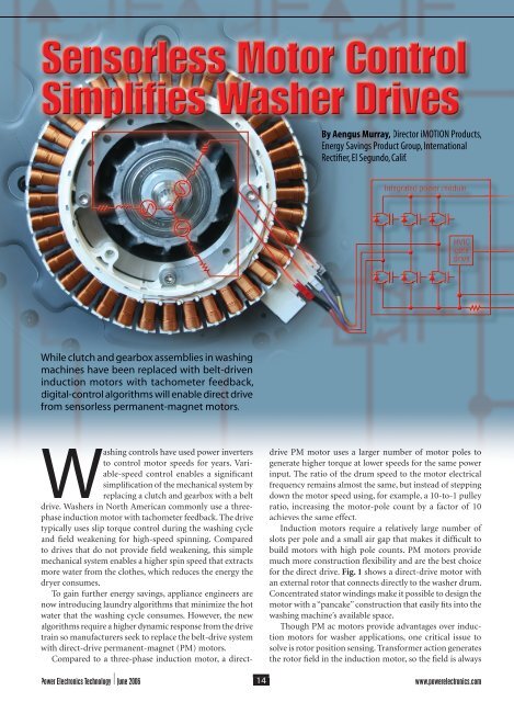
While clutch and gearbox assemblies in washing<br />
machines have been replaced with belt-driven<br />
induction motors with tachometer feedback,<br />
digital-control algorithms will enable direct drive<br />
from sensorless permanent-magnet motors.<br />
Washing controls have used power inverters<br />
to control motor speeds for years. Variable-speed<br />
control enables a signifi cant<br />
simplifi cation of the mechanical system by<br />
replacing a clutch and gearbox with a belt<br />
drive. Washers in North American commonly use a three<strong>phase</strong><br />
induction motor with tachometer feedback. The drive<br />
typically uses slip torque control during the washing cycle<br />
and fi eld weakening for high-speed spinning. Compared<br />
to drives that do not provide fi eld weakening, this simple<br />
mechanical system enables a higher spin speed that extracts<br />
more water from the clothes, which reduces the energy the<br />
dryer consumes.<br />
To gain further energy savings, appliance engineers are<br />
now introducing laundry algorithms that minimize the hot<br />
water that the washing cycle consumes. However, the new<br />
algorithms require a higher dynamic response from the drive<br />
train so manufacturers seek to replace the belt-drive system<br />
with direct-drive permanent-magnet (PM) motors.<br />
Compared to a three-<strong>phase</strong> induction motor, a direct-<br />
By Aengus Murray, Director iMOTION Products,<br />
Energy Savings Product Group, International<br />
Rectifi er, El Segundo, Calif.<br />
drive PM motor uses a larger number of motor poles to<br />
generate higher torque at lower speeds for the same power<br />
input. The ratio of the drum speed to the motor electrical<br />
frequency remains almost the same, but instead of stepping<br />
down the motor speed using, for example, a 10-to-1 pulley<br />
ratio, increasing the motor-pole count by a factor of 10<br />
achieves the same effect.<br />
Induction motors require a relatively large number of<br />
slots per pole and a small air gap that makes it diffi cult to<br />
build motors with high pole counts. PM motors provide<br />
much more construction fl exibility and are the best choice<br />
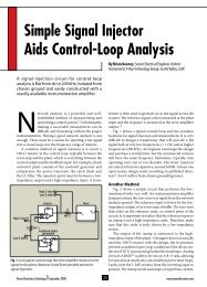
for the direct drive. Fig. 1 shows a direct-drive motor with<br />
an external rotor that connects directly to the washer drum.<br />
Concentrated stator windings make it possible to design the<br />
motor with a “pancake” construction that easily fi ts into the<br />
washing machine’s available space.<br />
Though PM ac motors provide advantages over induction<br />
motors for washer applications, one critical issue to<br />
solve is rotor position sensing. Transformer action generates<br />
the rotor fi eld in the induction motor, so the fi eld is always<br />
<strong>Power</strong> <strong>Electronics</strong> Technology June 2006 14<br />
www.powerelectronics.com
Fig. 1. The compact profi le of the stator windings (left) and rotor (right) permit a “pancake” form factor well suited for washing-machine<br />
applications.<br />
Field<br />
weakening<br />
Target<br />
velocity Velocity<br />
controller<br />
Rotor velocity ()<br />
Torque<br />
demand<br />
synchronous to the stator current. However, the motor-drive<br />
circuit must measure the rotor position in the PM machine<br />
to synchronize the stator current with the rotor fi eld. Given<br />
the rotor position, it is possible to drive the PM ac motor<br />
effi ciently because the drive circuit can align the stator current<br />
to the optimum angle relative to the rotor fi eld.<br />
In the direct-drive motor shown in Fig. 1, Hall Effect<br />
sensors detect the rotor-magnet position. However, designs<br />
that eliminate these sensors alleviate the reliability issues<br />
that result from mounting the sensor electronics assembly<br />
within the motor housing.<br />
One popular sensorless algorithm measures the rotorfl<br />
ux position based on the stator winding’s back EMF. This<br />
algorithm is suitable when driving the PM motor in six-step<br />
mode with rectangular winding currents. The algorithm<br />
is easy to implement but produces high torque ripple because<br />
of delays in current commutation due to the winding<br />
inductance.<br />
One of the major drawbacks of this scheme is that the<br />
torque ripple causes unacceptably high acoustic-noise levels<br />
I D *<br />
I D<br />
I Q *<br />
I Q<br />
I D<br />
controller<br />
I Q<br />
controller<br />
Rotating<br />
reference<br />
frame<br />
stator<br />
voltages<br />
V D<br />
V Q<br />
I D<br />
I Q<br />
Rotating<br />
reference frame<br />
stator currents<br />
e j<br />
Forward<br />
rotation<br />
in the direct-drive motor, as the rotor acts like a loud speaker.<br />
Another important problem with the back-EMF-sensing<br />
algorithm is that it does not allow high-speed fi eld weakening,<br />
which is required for high-speed spinning.<br />
Sensorless Control<br />
A sensorless control algorithm can use motor-windingcurrent<br />
measurements to indirectly determine the rotor-fl ux<br />
position. This algorithm allows for sinusoidal currents to<br />
drive the motor. These sinusoidal waveforms produce low<br />
torque ripple, which minimizes the acoustic noise. The<br />
control method also easily provides for fi eld-weakening<br />
operation for high-speed spinning.<br />
Typically, sensorless control algorithms determine the<br />
rotor-fl ux position based on the winding’s back EMF—an<br />
indirect measurement that derives from the motor circuit<br />
model. The advantage of this approach is that it is applicable<br />
when sinusoidal-current waveforms drive the motor, which<br />
produce smooth, glitch-free torque.<br />
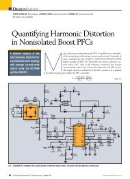
The control diagram in Fig. 2 describes the field-<br />
www.powerelectronics.com 15<br />
<strong>Power</strong> <strong>Electronics</strong> Technology June 2006<br />
V <br />
V <br />
Rotor angle ()<br />
e -j<br />
Reverse<br />
rotation<br />
I <br />
I <br />
2 - to - 3<br />
Clark<br />
Rotor-flux<br />
estimation<br />
algorithm<br />
3 - to - 2<br />
Clark -1<br />
Applied<br />
stator ac<br />
voltages<br />
V U<br />
V V<br />
V W<br />
I U<br />
I V<br />
I W<br />
Measured<br />
stator ac<br />
currents<br />
Permanent magnet<br />
synchronous motor<br />
Fig. 2. The permanent magnet synchronous motor (PMSM) fi eld-oriented-control algorithm transforms the stator’s three-<strong>phase</strong> ac currents<br />
into a rotating reference frame that tracks the rotor’s position.<br />
U<br />
V<br />
W
V <br />
I <br />
V <br />
I <br />
WASHER DRIVES<br />
R x cos( R ) + L S x I = (V – I x R S )dt<br />
R x sin( R ) + L S x I = (V – I x R S )dt<br />
Flux<br />
estimator<br />
R x sin( R )<br />
R x cos( R )<br />
oriented-control (FOC) algorithm for the permanent magnet<br />
synchronous motor (PMSM). A feature of this algorithm<br />
is that it transforms the three-<strong>phase</strong> ac currents in the stator<br />
windings into a rotating reference frame where they appear as<br />
two dc-current components representing the stator current’s<br />
torque and fl ux components.<br />
The reference transformations occur in two stages. The<br />
fi rst stage calculates the equivalent stator currents in a two<strong>phase</strong><br />
machine model. The second performs a vector rotation<br />
to calculate the stator currents’ effect in a reference frame<br />
synchronous with the rotor shaft.<br />
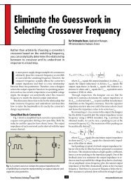
The two-<strong>phase</strong> stator-current model forms the basis for<br />
the rotor-fl ux-estimation algorithm, which is defi ned as:<br />
v R i L di α d<br />
v α = R S ×<br />
i α<br />
α + L S<br />
S +<br />
+ ( R R )<br />
dt dt<br />
θ ( ) θ<br />
R R θ ( R R ) θ ( − Ψ R ×<br />
× cos( R ) )<br />
)<br />
diβ<br />
d<br />
v = R × i + L × + − Ψ × sin( θ )<br />
β S β S R R<br />
dt<br />
e -j<br />
Estimated<br />
angle<br />
dt<br />
( ),<br />
Rotor<br />
velocity<br />
()<br />
Rotor<br />
angle<br />
()<br />
where R is the rotor fl ux.<br />
As shown in Fig. 3, the inputs are the stator voltages<br />
(v α and v β ) that the drive system provides and the statorcurrent<br />
measurements (i α and i β ). Calculations for the winding<br />
voltage’s back-EMF components use the stator-current<br />
measurements as input. Integration of the back-EMF components<br />
produces two rotor-fl ux components that are sine<br />
and cosine functions of the rotor angle.<br />
The second stage in the rotor-angle estimator is a <strong>phase</strong>locked<br />
loop that forces the sine and cosine of the angle<br />
estimate to track the sine and cosine rotor-fl ux functions,<br />
PI<br />
Phase-locked loop<br />
Fig. 3. Two-<strong>phase</strong> stator-current models form the basis of the rotor-fl uxestimation<br />
algorithm.<br />
AC<br />
input<br />
EMI<br />
filter<br />
Communication<br />
Isolation<br />
System<br />
I/O<br />
<strong>Power</strong><br />
supply<br />
1 s<br />
M<br />
C<br />
U<br />
8-bit<br />
300-Vdc bus<br />
Digital control IC<br />
RAM<br />
M<br />
C<br />
E<br />
16-bit<br />
PWM<br />
ADC<br />
respectively. This approach has the advantage of delivering<br />
both rotor-angle and velocity estimates, and is independent<br />
of the rotor-fl ux magnitude.<br />
The controller performs the current-control loop calculations<br />
within the rotating reference frame and compensates<br />
for the winding resistance, inductance and back-EMF magnitude.<br />
The input to the torque current loop comes from<br />
the outer velocity-control loop that compensates for the<br />
mechanical load’s dynamics. The fi eld-weakening controller<br />
sets the fl ux-current loop input to zero at low speeds to<br />
maximize the output torque.<br />
At the motor’s base speed, the back EMF due to the PM<br />
fl ux reaches the dc bus voltage. At this speed, drives without<br />
fi eld weakening would be unable to further increase the motor<br />
speed because, with the back EMF equal to the dc bus<br />
voltage, there is no excess voltage available with which to<br />
drive additional current.<br />
However, the fi eld-weakening controller can provide a<br />
negative input to buck a fraction of the PM fl ux that couples<br />
to the winding. This allows the fi eld-weakening controller to<br />
set motor speeds beyond the base speed. The advantage of<br />
the sensorless FOC implementation is that it delivers smooth<br />
torque with good dynamic control—without the use of any<br />
position sensors.<br />
Algorithm Implementation<br />
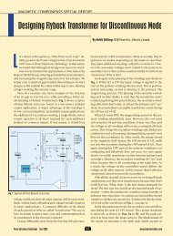
The hardware platform for the washing-machine controller<br />
consists of a digital control IC and an integrated power<br />
module, as appears in the application circuit in Fig. 4. An<br />
embedded 16-bit motion-control engine (MCE) implements<br />
the sensorless control algorithm that performs all of the<br />
control calculations using hardware macro blocks.<br />
There is an independent 8-bit microcontroller for the<br />
application software that communicates with the MCE<br />
using shared memory. The MCE connects directly to the<br />
motor-control peripherals that interface to the inverter<br />
power module that drives the motor.<br />
The PWM unit calculates the duty-cycle timing of the<br />
power transistors to control the voltage applied to each<br />
<strong>phase</strong> of the motor while the analog-to-digital converter<br />
(ADC) samples the motor currents fl owing in the dc-link<br />
shunt resistor.<br />
DC bus<br />
voltage<br />
Integrated power module<br />
Fig. 4. The main electronic components of the washing-machine controller are the digital control IC and the integrated<br />
power module.<br />
The high-voltage<br />
IC (HVIC),<br />
gate-drive circuit<br />
interfaces<br />
b e t ween t h e<br />
3.3-V logic-level<br />
outputs of the<br />
digital control<br />
IC and the power<br />
transistors.<br />
The HVIC also<br />
includes inverter-protection<br />
features such<br />
<strong>Power</strong> <strong>Electronics</strong> Technology June 2006 16<br />
www.powerelectronics.com<br />
HVIC<br />
gate<br />
drive<br />
PM<br />
motor
WASHER DRIVES<br />
as overcurrent<br />
shutdown that<br />
also use feedbackinformation<br />
from the<br />
dc-link shunt.<br />
The digital<br />
implementation<br />
of the FOC<br />
algorithm that<br />
appears in Fig.<br />
5 has the same<br />
basic structure<br />
as that in<br />
Fig. 2, with an<br />
outer velocity<br />
loop and two<br />
inner current<br />
loops for controlling<br />
the<br />
motor torque<br />
Target<br />
speed<br />
Closed-loop speed control Sensorless field-oriented control<br />
Ramp<br />
Velocity loop Limit<br />
Torque loop<br />
–<br />
PI<br />
IQ +<br />
–<br />
PI<br />
and fl ux. The other control functions include the rotor-angle<br />
estimation, fi eld weakening for high-speed operation and<br />
the <strong>phase</strong>-current reconstruction block. Practical imple-<br />
CKE-PET mentations ad need 5-06 additional 5/10/06 functions 1:03 PM such Page as those 1<br />
that the<br />
startup-sequencer and fault-detection blocks provide.<br />
+<br />
VD VQ ID REF<br />
Field<br />
weakening<br />
REF<br />
+<br />
= 0 below<br />
base speed<br />
Estimated speed<br />
Startup<br />
sequencer<br />
–<br />
Each control-loop compensator has a proportional-plusintegral<br />
(PI) block with a limiting function at its output. The<br />
output of the velocity loop, which is the reference input to<br />
the torque loop, is limited so that the controller does not<br />
drive too much current into the motor. The controller limits<br />
the current-loop outputs to a voltage range that the power<br />
inverter can deliver. An output from each limit block halts<br />
the integration upon reaching the limit, to prevent unwanted<br />
integrator windup while the controller is saturated.<br />
The vector-rotation block (e j ) transforms the currentloop<br />
outputs to ac quantities in the stator-reference frame.<br />
The two-<strong>phase</strong> stator-reference voltages directly feed the<br />
space-vector PWM block that controls the voltages to the<br />
motor since the modulation algorithm has an embedded<br />
two- to three-<strong>phase</strong> transformation.<br />
The most diffi cult part of the rotor-angle-estimator<br />
implementation is in the low-speed range. The fl ux-estimator<br />
algorithm’s integrators have a low frequency cutoff<br />
to avoid saturation due to dc offsets. At start up, the back<br />
EMF is zero and so the motor must start without position<br />
feedback.<br />
The fi rst stage of the startup algorithm parks the rotor<br />
in known position by driving dc currents into the stator<br />
windings. In the second stage, the rotor fl ux estimator is in<br />
open-loop mode, and the estimator’s angular velocity output<br />
signal increases at a constant rate. In this mode the torquereference<br />
current (I QREF ) is a constant value to deliver a torque<br />
that will accelerate the motor at the rate equal to the angular<br />
velocity output of the rotor-fl ux estimator.<br />
If the motor torque is greater than that which the system<br />
requires to match the estimator acceleration, the rotor will<br />
advance in <strong>phase</strong> and move out of optimum alignment.<br />
However, since the motor torque function is a cosine function<br />
of this alignment, the rotor angle advances until the<br />
motor torque exactly matches the target value.<br />
<strong>Power</strong> <strong>Electronics</strong> Technology June 2006 18<br />
www.powerelectronics.com<br />
Flux loop<br />
PI<br />
I Q<br />
I D<br />
Limit<br />
Limit<br />
V D<br />
Estimated angle<br />
Rotor-flux<br />
estimator<br />
e -j<br />
V Q<br />
I <br />
I <br />
e j<br />
3 - to - 2<br />
Clark -1<br />
Carrier frequency<br />
V Space<br />
6<br />
V vector<br />
PWM<br />
I U<br />
I V<br />
I W<br />
Fault<br />
detection<br />
Phasecurrent<br />
reconstruction<br />
Current<br />
sample<br />
timing<br />
Three<strong>phase</strong><br />
inverter<br />
gate-drive<br />
signals<br />
Fault<br />
DC bus<br />
current<br />
(measured<br />
by shunt<br />
resistor)<br />
Fig. 5. The digital implementation of the fi eld-oriented-control algorithm has one outer velocity-control loop and two inner<br />
current loops for torque and fl ux control.<br />
CKE manufactures<br />
a wide range of<br />
metal oxide varistors<br />
(MOVs) for your unique<br />
requirements. r<br />
From low<br />
voltage radial leadstyles<br />
to high energy packages,<br />
we build to OEM specs<br />
or provide direct<br />
replacements.<br />
r<br />
CKE<br />
Lucernemines, PA 15754<br />
(724) 479-3533 (724) 479-3537 FAX<br />
e-mail: info@cke.com www.cke.com
WASHER DRIVES<br />
At 5% of the rated velocity, by which point a measurable<br />
level of back EMF develops, the estimator switches into the<br />
closed-loop mode. The feedback loops are then controlled<br />
by the estimated angle and estimated speed signals from the<br />
rotor-fl ux estimator.<br />
Implementation Issues<br />
Designers must face several practical considerations when<br />
implementing the control algorithm in fi xed-point hardware.<br />
The most important decision is the selection of control-variable<br />
scaling, which must allow a good dynamic signal range<br />
while avoiding calculation overfl ow. The resolution of the<br />
digital-to-analog interface circuits could defi ne the controlvariable<br />
scaling, but this does not ensure numerical stability<br />
of the control-loop functions. Fixed control-variable scaling<br />
simplifi es the design of the control-loop functions with the<br />
minor additional complexity of the feedback-gain scaling.<br />
Since velocity is a user input, its scaling requires the<br />
highest resolution. To defi ne the velocity scaling for a 16bit<br />
platform, the maximum operating drive speed is set to<br />
equal +16383(~2 14 ), which allows 1 bit of headroom in case<br />
of overshoot.<br />
The velocity value that the rotor-angle estimator calculates<br />
is the change in rotor-angle count in every control-loop<br />
cycle. The scaling of this value depends on the loop sample<br />
rate, the number of motor poles and the maximum rotor-<br />
angle count. The feedback-gain scaling is then the ratio<br />
of 16384 to the angle-estimator output at the maximum<br />
operating speed.<br />
Similarly, the current-variable scaling is defi ned by setting<br />
the name-plate-rated motor current equal to +4095 (~2 12 )<br />
counts. This allows suffi cient headroom for the current<br />
controller to operate the motor in short-term overload. The<br />
gain of the current-feedback circuits depends on the current-sense<br />
resistor values, the buffer amplifi ers’ gains, and<br />
the ADC’s input range and resolution. The current-sense<br />
resistor is also useful for protection.<br />
The value selected should trip the power inverter before<br />
the motor current reaches its demagnetization limit. The<br />
buffer amplifi er’s gain defi nes the operating range of current-control<br />
loop since the ADC will saturate when the input<br />
signal is out of range. The resolution of the vector-rotation<br />
block, which requires all inputs to be in the 11-bit-plus sign<br />
range, sets the voltage scaling in the case of this hardware<br />
implementation.<br />
The actual voltage scaling is a function of the maximum<br />
voltage count and the dc-bus voltage. However, the dc-bus<br />
voltage can change with either input ac voltage or the load,<br />
and so a bus-voltage measurement contributes to the scaling<br />
calculation.<br />
Control Algorithm Tuning<br />
The fi nal stage in the control algorithm design is in the<br />
calculation of the feedback-gain parameters. The process<br />
usually involves an element of trial and error, but there are<br />
design tools that provide close-to-optimum values. Pole-zero<br />
placement is a well-known technique that works well with<br />
systems such as the current-control loop, whose parameters<br />
are given to easy measurement.<br />
The system model of the current controller in Fig. 6 illustrates<br />
the technique. Gain elements, which the selection of<br />
voltage and current scaling defi ne, model the PWM-inverter<br />
and current-feedback circuits. A continuous-time-domain<br />
<strong>Power</strong> <strong>Electronics</strong> Technology June 2006 20<br />
www.powerelectronics.com<br />
I* +<br />
–<br />
K L P<br />
Stage 1: = for pole-zero cancellation<br />
K R I<br />
<br />
A x B x KI Stage 2: C = to set closed-loop bandwidth ( ) C R<br />
Stage 3:<br />
(<br />
K P s + K I<br />
s<br />
T SAMPLE)<br />
2<br />
Proportional-plusintegral<br />
controller<br />
scaling factor for K I to calculate<br />
gain in the digital algorithm<br />
PWM inverter<br />
V (counts) V (volts) 1<br />
A<br />
R + sL<br />
I (counts) I (amps)<br />
B<br />
Motor winding<br />
(dynamic)<br />
Current feedback<br />
Fig. 6. Current-loop tuning using pole-zero cancellation is executed in<br />
three stages.
IRMCF3341- Reference design<br />
8051<br />
running MCE<br />
interface<br />
software<br />
Shared<br />
memory<br />
8051<br />
memory<br />
Motion<br />
control<br />
engine<br />
(MCE)<br />
PWM<br />
and<br />
ADC<br />
AC input<br />
Rectifier<br />
IRAM<br />
JTAG UART<br />
8051 tools<br />
MCE Tools<br />
WASHER DRIVES<br />
PM<br />
motor<br />
Fig. 7. Design tools for the washing-machine design platform include<br />
a spreadsheet for calculating controller constants based on motor<br />
parameters and system specifi cations. A second tool, MCEDesigner,<br />
transmits the constants to the embedded microcontroller.<br />
model simplifi es the fi gure, but a sampled-data model only<br />
requires some additional scaling of the integrator-gain<br />
parameter.<br />
As shown in Fig. 6, the PI-controller gains are calculated<br />
in three stages. First, to reduce the order of the loop, select the<br />
ratio of the PI compensator gains so that its zero cancels the<br />
pole in the motor-winding model. Next, select the integral<br />
gain so that the closed-loop bandwidth matches the target<br />
specifi cations. Finally, scale the integral-gain parameter by<br />
half of the sample period to calculate the gain in the digital<br />
implementation.<br />
The calculation of gain parameters for the current loop is<br />
straightforward, but the next section describes some of the<br />
tools for tuning the velocity loop when driving the type of<br />
complex load found in washing-machine applications.<br />
Simplifying Drive Commissioning<br />
The washing-machine design platform includes a digital<br />
IC with the control algorithm already embedded (Fig. 7).<br />
The MCE implements the algorithm in hardware based<br />
on parameters and variables that the shared-memory area<br />
stores. One of the available design tools is a spreadsheet that<br />
calculates the controller constants that match the motor<br />
parameters and system specifi cations.<br />
The second tool is MCEDesigner, which transmits the<br />
controller constants from a PC to an interface program<br />
running on the embedded 8051 microcontroller. The 8051<br />
copies the parameters to the block of shared memory before<br />
the MCE starts running the motor.<br />
Another important function of the 8051 interface software<br />
is to capture trace data from the MCE, which gives the<br />
user access to all the control-system variables. MCEDesigner<br />
also generates speed profi les that allow users to evaluate drive<br />
performance in the washer application. The combination<br />
of an embedded motor control algorithm and easy-to-use<br />
evaluation tools simplifi es the evaluation of direct-drive<br />
motors for washer applications. PETech<br />
For superior solutions:<br />
Aluminum electrolytic<br />
capacitors<br />
Low inductance<br />
High temperature range<br />
Very high ripple current capability<br />
Very long service life<br />
More information at www.epcos.com<br />
electronica Munich, Germany<br />
November 14 to 17, 2006<br />
Hall B5, Stand B5.506<br />
www.powerelectronics.com <strong>Power</strong> <strong>Electronics</strong> Technology<br />
just everywhere …