Hardware Manual v1.4 - Research Services
Hardware Manual v1.4 - Research Services
Hardware Manual v1.4 - Research Services

Create successful ePaper yourself
Turn your PDF publications into a flip-book with our unique Google optimized e-Paper software.
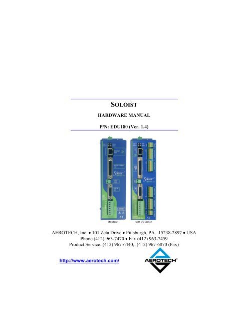
SOLOIST<br />
HARDWARE MANUAL<br />
P/N: EDU180 (Ver. 1.4)<br />
AEROTECH, Inc. 101 Zeta Drive Pittsburgh, PA. 15238-2897 USA<br />
Phone (412) 963-7470 Fax (412) 963-7459<br />
Product Service: (412) 967-6440; (412) 967-6870 (Fax)<br />
http://www.aerotech.com/
Product Registration<br />
To register your Soloist, use the product registration form that is available online at:<br />
http://www.aerotech.com/prodreg.cfm<br />
Technical Support<br />
For technical support, contact one of the following:<br />
United States (Headquarters):<br />
Phone: (412) 967-6440<br />
Fax: (412) 967-6870<br />
Email: service@aerotech.com<br />
United Kingdom:<br />
Phone: +44 (0)118 940 9420<br />
Fax: +44 (0)118 940 9428<br />
Email: service@aerotech.co.uk<br />
Germany:<br />
Phone: (49-911) 967937-0<br />
Fax: (49-911) 967937-21<br />
Email: service@aerotechgmbh.de<br />
Product names mentioned herein are used for identification purposes only and may be trademarks of their respective<br />
companies.<br />
Soloist is a trademark of Aerotech, Inc.<br />
The Soloist User’s <strong>Manual</strong> Revision History:<br />
Ver. 1.0 October 12, 2004<br />
Ver. 1.1 December 8, 2004<br />
Ver. 1.2 December 23, 2004<br />
Ver. 1.3 February 28, 2005<br />
Ver. 1.4 April 12, 2005<br />
© Aerotech, Inc., 2005
Soloist <strong>Hardware</strong> <strong>Manual</strong> Table of Contents<br />
TABLE OF CONTENTS<br />
CHAPTER 1: INTRODUCTION.............................................................................1-1<br />
1.1 Chapter Overview ...............................................................................1-1<br />
1.2 Feature Summary ................................................................................1-2<br />
1.2.1 Power Amplifier................................................................... 1-2<br />
1.2.2 Dual Encoder Feedback Channels ....................................... 1-2<br />
1.2.3 Inputs and Outputs ............................................................... 1-2<br />
1.2.4 -IO Option Feature Summary............................................... 1-2<br />
1.3 Soloist Connections.............................................................................1-3<br />
1.4 Soloist Power Features........................................................................1-4<br />
1.5 Soloist Voltage Configurations ...........................................................1-5<br />
1.6 Electrical Specifications......................................................................1-6<br />
1.7 Physical Dimensions ...........................................................................1-8<br />
1.8 Environmental Specifications..............................................................1-9<br />
CHAPTER 2: INSTALLATION AND CONFIGURATION .................................2-1<br />
2.1 Introduction.........................................................................................2-1<br />
2.2 Safety Procedures and Warnings.........................................................2-2<br />
2.3 Motor and AC Power Connections .....................................................2-3<br />
2.4 Wiring, Grounding, and Shielding Techniques ...................................2-4<br />
2.4.1 Minimizing EMI Interference .............................................. 2-4<br />
2.4.2 AUXPWR (Auxiliary Power) Option .................................. 2-5<br />
2.4.3 40/80 VDC Power Transformers ......................................... 2-5<br />
2.5 Typical AC Wiring with the -AUXPWR Option and an<br />
External Transformer ..........................................................................2-6<br />
2.5.1 Minimizing 50/60 HZ Line Interference.............................. 2-9<br />
2.5.2 I/O and Signal Wiring Requirements................................... 2-9<br />
2.6 Emergency Stop Sense Input (TB101)..............................................2-10<br />
2.6.1 Typical ESTOP Interface................................................... 2-11<br />
2.7 Motor Connections............................................................................2-12<br />
2.7.1 DC Brush Motor Connections in Torque Mode................. 2-12<br />
2.7.1.1 DC Brush Motor Phasing .................................... 2-12<br />
2.7.2 Brushless Motor Connections ............................................ 2-13<br />
2.7.2.1 Brushless Motor Phasing ..................................... 2-14<br />
2.7.2.2 Brushless Motor Hall Effect Feedback<br />
Connections ......................................................... 2-15<br />
2.7.2.3 Hall Effect Phasing.............................................. 2-16<br />
2.7.3 Stepper Motor Connections ............................................... 2-18<br />
2.7.3.1 Stepper Motor Phasing Process ........................... 2-18<br />
2.8 Encoder Feedback Connections ........................................................2-19<br />
2.8.1 Encoder Phasing ................................................................ 2-20<br />
2.9 End of Travel Limit Connections......................................................2-21<br />
2.9.1 End of Travel Limit Phasing.............................................. 2-21<br />
2.10 Communication Channel Settings .....................................................2-22<br />
2.11 Soloist Help Information...................................................................2-24<br />
CHAPTER 3: TECHNICAL DETAILS ..................................................................3-1<br />
3.1. Port 0 I/O and the Secondary Encoder Channel (J104).......................3-1<br />
www.aerotech.com iii
Table of Contents Soloist <strong>Hardware</strong> <strong>Manual</strong><br />
3.1.1. Secondary Encoder Channel (J104)..................................... 3-3<br />
3.1.2. Port 0 User Digital Outputs (J104) ...................................... 3-5<br />
3.1.3. Port 0 User Digital Inputs (J104) ......................................... 3-8<br />
3.1.4. User Analog Output 0 (J104)............................................. 3-11<br />
3.1.5. User Analog Input 0 (J104)................................................ 3-12<br />
3.2. Position Synchronized Output (PSO)................................................3-13<br />
3.3. Motor Feedback (J103) .....................................................................3-15<br />
3.3.1. MXU Option...................................................................... 3-17<br />
3.3.2. Brake / Relay Interface (J103, TB103) .............................. 3-18<br />
3.4. RS-232 Serial Port (TB103)..............................................................3-19<br />
3.5. USB Port (J101)*..............................................................................3-20<br />
CHAPTER 4: SOLOIST OPTIONS ....................................................................... 4-1<br />
4.1. Introduction.........................................................................................4-1<br />
4.2. -IO Option Board ................................................................................4-2<br />
4.2.1. Analog Input 1 (TB201)....................................................... 4-2<br />
4.2.2. Analog Output 1 (TB201).................................................... 4-3<br />
4.2.3. Port 1 and Port 2 Opto-Isolated Outputs (TB202,<br />
TB203)................................................................................. 4-4<br />
4.2.4. Port 1 and Port 2 Opto-Isolated Inputs (TB204,<br />
TB205)................................................................................. 4-6<br />
4.2.5. User Power (TB204, TB205)............................................... 4-9<br />
4.2.6. Brake / Relay (TB206)......................................................... 4-9<br />
4.2.6.1. Brake Configuration Jumpers .............................. 4-10<br />
CHAPTER 5: ACCESSORIES................................................................................ 5-1<br />
5.1. Standard Interconnection Cables.........................................................5-1<br />
5.2. Joystick Interface.................................................................................5-5<br />
5.3. Handwheel Interface............................................................................5-7<br />
CHAPTER 6: TROUBLESHOOTING................................................................... 6-1<br />
6.1. Problems, Causes, and Solutions.........................................................6-1<br />
6.2. Soloist Test Points...............................................................................6-3<br />
6.3. Fuse Replacement................................................................................6-4<br />
6.4. Soloist Board Assembly ......................................................................6-5<br />
6.5. Preventative Maintenance ...................................................................6-7<br />
6.5.1. Cleaning ............................................................................... 6-7<br />
APPENDIX A: GLOSSARY OF TERMS ................................................................A-1<br />
APPENDIX B: WARRANTY AND FIELD SERVICE...........................................B-1<br />
APPENDIX C: TECHNICAL CHANGES ...............................................................C-1<br />
INDEX<br />
C.1. Current Changes.................................................................................C-1<br />
C.2. Archive of Changes ............................................................................C-2<br />
<br />
iv www.aerotech.com
Soloist <strong>Hardware</strong> <strong>Manual</strong> List of Figures<br />
LIST OF FIGURES<br />
Figure 1-1 Soloist in TwoVersions .......................................................................1-1<br />
Figure 1-2 Soloist <strong>Hardware</strong>.................................................................................1-3<br />
Figure 1-3 Soloist Block Diagram ........................................................................1-4<br />
Figure 1-4 Soloist Physical Dimensions ...............................................................1-8<br />
Figure 2-1 -AUXPWR Option..............................................................................2-5<br />
Figure 2-2 40 Volt DC Bus from 115 and 230 VAC Source ................................2-6<br />
Figure 2-3 80 Volt DC Bus from 115 and 230 VAC Source ................................2-7<br />
Figure 2-4 160 Volt DC Bus from 115 and 230 VAC Source ..............................2-8<br />
Figure 2-5 Back-Propagation Line Filter Connection...........................................2-9<br />
Figure 2-6 ESTOP Sense Input (TB101)............................................................2-10<br />
Figure 2-7 Typical Emergency Stop Circuit .......................................................2-11<br />
Figure 2-8 DC Brush Motor (Torque Mode) Connections .................................2-12<br />
Figure 2-9 Brushless Motor Connections ...........................................................2-13<br />
Figure 2-10 Hall Effect Feedback Connections ....................................................2-15<br />
Figure 2-11 Hall Effect Feedback Inputs in the Soloist HMI Program.................2-15<br />
Figure 2-12 Motor Phasing...................................................................................2-17<br />
Figure 2-13 Stepper Motor Connections...............................................................2-18<br />
Figure 2-14 Encoder Feedback Connections ........................................................2-19<br />
Figure 2-15 Encoder Phasing Reference Diagram................................................2-20<br />
Figure 2-16 Encoder Feedback in the Soloist HMI ..............................................2-20<br />
Figure 2-17 Limit Inputs in the Soloist HMI Program..........................................2-21<br />
Figure 2-18 Limit Inputs in the Soloist HMI Program..........................................2-21<br />
Figure 3-1. PSO Interface (J104)...........................................................................3-3<br />
Figure 3-2. Primary / Secondary Encoder Channels (J103, J104) .........................3-4<br />
Figure 3-3. User Outputs (J104) ............................................................................3-6<br />
Figure 3-4. Outputs Connected as Current Sinking ...............................................3-7<br />
Figure 3-5. Outputs Connected as Current Sourcing .............................................3-7<br />
Figure 3-6. Connecting Current Sinking Inputs .....................................................3-9<br />
Figure 3-7. Connecting Current Sourcing Inputs ...................................................3-9<br />
Figure 3-8. Low Speed and High Speed User Inputs (J104)................................3-10<br />
Figure 3-9. Analog Output 0 (J104).....................................................................3-11<br />
Figure 3-10. Analog Input 0 (J104) .......................................................................3-12<br />
Figure 3-11. PSO Block Diagram..........................................................................3-14<br />
Figure 3-12. Data Capture/Data Update Modes.....................................................3-14<br />
Figure 3-13. Limit, Thermistor and Hall-Effect Inputs (J103)..............................3-16<br />
Figure 3-14. Optional -MXU Analog Encoder Interface (J103)............................3-17<br />
Figure 3-15. Brake Connector (TB103).................................................................3-18<br />
Figure 3-16. RS-232 Connector (TB103)..............................................................3-19<br />
Figure 4-1. –IO Option Board (690D1611 Rev. 0)................................................4-2<br />
Figure 4-2. Optional Analog Input Connector (TB201) ........................................4-2<br />
Figure 4-3. Analog Output Connector (TB201).....................................................4-3<br />
Figure 4-4. Connecting Outputs in Current Sinking Mode ....................................4-5<br />
Figure 4-5. Connecting Outputs in Current Sourcing Mode ..................................4-5<br />
Figure 4-6. Inputs Connected in Current Sourcing Mode......................................4-7<br />
Figure 4-7. Inputs Connected in Current Sinking Mode ........................................4-8<br />
www.aerotech.com v
List of Figures Soloist <strong>Hardware</strong> <strong>Manual</strong><br />
Figure 4-8. Brake Connected to TB206...............................................................4-11<br />
Figure 4-9. Brake Connected to J103 ..................................................................4-11<br />
Figure 4-10. Suppression for DC Brake Systems...................................................4-13<br />
Figure 5-1. Joystick Interface.................................................................................5-5<br />
Figure 5-2. Single Axis Joystick Interface to J104 of the Soloist ..........................5-6<br />
Figure 5-3. Single Axis Joystick Interconnect to J104 of the Soloist.....................5-6<br />
Figure 5-4. Handwheel Interconnection to J104 of the Soloist ..............................5-7<br />
Figure 5-5. Handwheel with Flying Leads (No Connector) ...................................5-8<br />
Figure 5-6. BBA32 Interface Used to Connect a Handwheel with Flying<br />
Leads (No Connector) .........................................................................5-9<br />
Figure 6-1. Soloist Board Assembly (690D1591 Rev. -).......................................6-5<br />
<br />
vi www.aerotech.com
Soloist <strong>Hardware</strong> <strong>Manual</strong> List of Tables<br />
LIST OF TABLES<br />
Table 1-1 Soloist Voltage Configurations................................................................1-5<br />
Table 1-2 Electrical Specifications...........................................................................1-6<br />
Table 2-1 Main AC Power Input and Motor Output (TB102)..................................2-3<br />
Table 2-2 -AUXPWR AC Input Option (when TB102 AC input < 85 VAC)..........2-3<br />
Table 2-3 Wire Part Numbers ..................................................................................2-4<br />
Table 2-4 ESTOP Input Voltage Jumper ...............................................................2-10<br />
Table 2-5. Electrical Noise Suppression Devices....................................................2-10<br />
Table 2-6 Soloist Switch Settings (S1)...................................................................2-23<br />
Table 3-1. Auxiliary I/O Connector Mating Connector (J104) .................................3-1<br />
Table 3-2. Auxiliary I/O Connector Pin out (J104)...................................................3-2<br />
Table 3-3. Secondary Encoder Connector Pin-out (J104).........................................3-3<br />
Table 3-4. Port 0 Digital Output Connector Pin-out (J104) ......................................3-5<br />
Table 3-5. Opto Outputs 0-3 Specifications ..............................................................3-5<br />
Table 3-6. Port 0 Digital Input Connector Pin out (J104) .........................................3-8<br />
Table 3-7. Analog Output Connector Pin-outs (J104).............................................3-11<br />
Table 3-8. Optional Analog Input Connector Pin-outs (J104).................................3-12<br />
Table 3-9. PSO Output Source................................................................................3-13<br />
Table 3-10. Motor Feedback Connector Mating Connector (J103) ..........................3-15<br />
Table 3-11. Motor Feedback Connector Pin out (J103)............................................3-16<br />
Table 3-12. Brake Power Input Pin-out on Connector TB103 ..................................3-18<br />
Table 3-13. Brake/Relay Output Pin-out on Connector J103....................................3-18<br />
Table 3-14. TB103 RS-232 Connector Pin-out.........................................................3-19<br />
Table 3-15. RS-232 Port Connector Mating Connector (TB103) .............................3-19<br />
Table 4-1. Soloist Options.........................................................................................4-1<br />
Table 4-2. Optional Analog Input Connector Pin-out (TB201) ...............................4-2<br />
Table 4-3. Analog Output Connector Pin-out (TB201).............................................4-3<br />
Table 4-4. Port 1 Opto-Isolated Output Connector Pin-out (TB202)........................4-4<br />
Table 4-5. Port 2 Opto-Isolated Output Connector Pin-out (TB203)........................4-4<br />
Table 4-6. Output Specifications (TB202, TB203)...................................................4-4<br />
Table 4-7. Port 1 Opto-Isolated Input Connector Pin-out (TB204) .........................4-6<br />
Table 4-8. Port 2 Opto-Isolated Input Connector Pin-out (TB205) .........................4-7<br />
Table 4-9. User Common Connector Pin out (TB204) .............................................4-9<br />
Table 4-10. +5 Volt Power Connector Pin out (TB205) .............................................4-9<br />
Table 4-11. –IOPSO Option Board Jumpers...............................................................4-9<br />
Table 4-12. Voltage and Current Specifications (TB206).........................................4-10<br />
Table 4-13. Brake / Relay Connector Pin-out (TB206).............................................4-10<br />
Table 4-14. Brake / Relay Connector Pin-out (J103) ................................................4-10<br />
Table 5-1. Standard Interconnection Cables .............................................................5-1<br />
Table 5-2. Combined Motor & Feedback Cables......................................................5-2<br />
Table 5-3. Individual Motor Cables ..........................................................................5-3<br />
Table 5-4. Individual Feedback Cables.....................................................................5-4<br />
Table 6-1. Amplifier Faults, Causes, and Solutions ..................................................6-2<br />
Table 6-2. Soloist Control Board Test Points............................................................6-3<br />
www.aerotech.com vii
List of Tables Soloist <strong>Hardware</strong> <strong>Manual</strong><br />
Table 6-3. -IO Option Board Test Points ..................................................................6-3<br />
Table 6-4. Soloist Fuse Information ..........................................................................6-4<br />
Table 6-5. -IO Board Fuse Information.....................................................................6-4<br />
Table 6-6. Soloist Jumper Selections ........................................................................6-6<br />
Table 6-7. Preventative Maintenance ........................................................................6-7<br />
Table C-1. Current Changes......................................................................................C-1<br />
<br />
viii www.aerotech.com
Soloist <strong>Hardware</strong> <strong>Manual</strong> Regulatory Information<br />
DECLARATION OF CONFORMITY<br />
Manufacturer’s Name and Address<br />
Aerotech, Inc.<br />
101 Zeta Drive<br />
Pittsburgh, PA 15238-2897<br />
Declares that the product:<br />
Product Name: Soloist<br />
Conforms to the following product specifications, with the exceptions listed below.<br />
Safety: EN 61010-1:1993 Safety Requirements<br />
and complies with EMC directive 89/336/EEC and 73/23/EEC low voltage directive.<br />
General notes concerning the test setup.<br />
Safety related requirements to ensure compliance:<br />
Soloist must be installed within an enclosure with construction compliant<br />
unlimited circuits.<br />
Pittsburgh, PA David F. Kincel_________________________<br />
September, 2004 Quality Assurance Manager<br />
General notes concerning the test setup.<br />
Safety related requirements to ensure compliance:<br />
Exceptions to EN 61010-1:<br />
Alex Weibel ___________________________<br />
Engineer Verifying Compliance<br />
Soloist must be installed within an enclosure with construction compliant for<br />
unlimited circuits.<br />
End user is responsible for meeting final protective ground requirements.<br />
AC power disconnect is AC power cord located on front panel of Soloist. End<br />
user is responsible for determining and providing supply disconnect for system.<br />
End user is responsible for preventing unexpected startup.<br />
Connection requirements are described in the technical documentation provided<br />
with the system. End user is responsible for making proper connections and<br />
meeting any required interlock requirements for application.<br />
www.aerotech.com ix
Regulatory Information Soloist <strong>Hardware</strong> <strong>Manual</strong><br />
Voltages greater than 60 Volts may be present inside Soloist after a discharge<br />
time of 5 seconds.<br />
End user must provide protection concerning power interruption / restoration if<br />
required.<br />
End user must provide earth fault current protection if required.<br />
" End user must provide protection against lightning and switching surges if<br />
required.<br />
Control and EStop requirements are determined and provided by the end user.<br />
" Wire and cabling provided with the Soloist meets Aerotech’s electrical and listed<br />
environmental requirements. End user must meet final requirements.<br />
Failure to follow the described procedures could result in serious injury and/or damage to<br />
the equipment.<br />
# # #<br />
x www.aerotech.com
Soloist <strong>Hardware</strong> <strong>Manual</strong> Introduction<br />
CHAPTER 1: INTRODUCTION<br />
In This Section:<br />
Chapter Overview...................................................... 1.1<br />
Feature Summary ....................................................... 1.2<br />
Soloist Connections .................................................. 1.3<br />
Soloist Power ............................................................ 1.4<br />
Voltage Configurations.............................................. 1.5<br />
Electrical Specifications ............................................ 1.6<br />
Physical Dimensions ................................................. 1.8<br />
Environmental Specifications .................................... 1.9<br />
1.1 Chapter Overview<br />
Use this chapter to become familiar with the features on your Soloist. This chapter<br />
includes electrical, mechanical, and environmental specifications.<br />
Figure 1-1 Both Versions of the Soloist<br />
www.aerotech.com 1-1
Introduction Soloist <strong>Hardware</strong> <strong>Manual</strong><br />
1.2 Feature Summary<br />
Review the following summary of the standard and optional features of the Soloist.<br />
1.2.1 Power Amplifier<br />
Configure for brush, brushless, and stepper motor operation<br />
Standard 100 VDC – 320 VDC, optional 10 VDC – 320 VDC bus operation<br />
Fully isolated power stage<br />
Full protection against the following failure modes:<br />
1. Control supply under voltage<br />
2. Continuous current overload<br />
3. Power stage bias supply under voltage<br />
4. Power stage output short circuit (phase to phase and phase to ground)<br />
5. DC bus over voltage<br />
6. IGBT (isolated gate bipolar transistor) device over temperature sense<br />
Keep alive and -AUXPWR option for emergency stop (estop) applications<br />
Inrush current limiting<br />
Internal or external shunt option<br />
1.2.2 Dual Encoder Feedback Channels<br />
Primary Channel: Line driver square wave or optional analog sine wave<br />
quadrature encoder primary position and velocity feedback<br />
Secondary Channel: Line driver square wave auxiliary quadrature encoder input<br />
1.2.3 Inputs and Outputs<br />
Four opto-isolated user outputs standard<br />
Six opto-isolated user inputs standard, two of which are high speed<br />
One differential analog input standard<br />
One analog output standard<br />
Dedicated 24 V E-stop sense input standard (5 V optional)<br />
Integral 24 V brake output interface<br />
5 VDC, 500 mA user output power for encoder and Hall effect signals<br />
1.2.4 -IO Option Feature Summary<br />
16 additional opto-isolated user outputs<br />
16 additional opto-isolated user inputs<br />
One additional differential analog input<br />
One additional analog output<br />
One additional Brake/Relay Output<br />
1-2 www.aerotech.com
Soloist <strong>Hardware</strong> <strong>Manual</strong> Introduction<br />
1.3 Soloist Connections<br />
The Soloist AC power, motor power, feedback, and communications connections are<br />
detailed in Figure 1-2.<br />
Figure 1-2 Soloist <strong>Hardware</strong><br />
www.aerotech.com 1-3
Introduction Soloist <strong>Hardware</strong> <strong>Manual</strong><br />
1.4 Soloist Power Features<br />
If you purchased the Soloist with the standard set of features, it includes the bus power<br />
supply that operates from 70-240 VAC (100 – 340 VDC). The power supply provides<br />
off-line operation without the need for an isolation transformer. A soft start circuit is<br />
included to prevent high inrush currents. These features are detailed in the following<br />
diagram. Note: Figure 1-3 includes power options.<br />
Figure 1-3 Soloist Block Diagram<br />
1-4 www.aerotech.com
Soloist <strong>Hardware</strong> <strong>Manual</strong> Introduction<br />
1.5 Soloist Voltage Configurations<br />
The Soloist is available in three models with continuous power, ranging from 1,100 to<br />
2,300 watts. The available voltage configurations and power options for these models are<br />
shown in Table 1-1.<br />
Table 1-1 Soloist Voltage Configurations<br />
Model Peak Output Current Continuous Output Current (peak)<br />
Soloist10 10A 5A<br />
Soloist20 20A 10A<br />
Soloist30-S 30A 15A<br />
-S<br />
Options<br />
Shunt resistor network, standard on Soloist30<br />
Auxiliary 115/230 VAC input to power logic circuitry; required for “keep alive”<br />
-AUXPWR or 10-40 VDC bus operation. 10-40 VDC operation requires external<br />
transformer to generate 7-28 VAC bus power input.<br />
-IO<br />
I/O option, adds 16 digital opto-inputs, 16 digital opto-outputs, 18-bit analog<br />
output and 16-bit analog input and a brake/relay output.<br />
Low bus voltage option for 40-100 VDC bus; doesn’t support keep-alive<br />
-LB functionality; not available with -AUXPWR option; 40-100 VDC bus operation<br />
requires external transformer to generate 28-70 VAC bus power input<br />
-MXU x512 (total) software encoder resolution multiplication (primary channel only)<br />
-S Shunt option (standard on Soloist30)<br />
www.aerotech.com 1-5
Introduction Soloist <strong>Hardware</strong> <strong>Manual</strong><br />
1.6 Electrical Specifications<br />
The electrical specifications for the Soloist are listed in Table 1-2.<br />
Table 1-2 Electrical Specifications<br />
Description Units Soloist10 Soloist20 Soloist30<br />
Input Volts<br />
Main Supply 70 - 240 VAC<br />
VAC<br />
-AUXPWR (1)<br />
Input Frequency Main Supply Hz 50-60<br />
Current (Max Peak)<br />
Max Continuous<br />
Input Power<br />
Main Supply<br />
Amps 42<br />
Main Supply Watts 1200 2400 2400<br />
Supply Input Volts VAC 70-240<br />
-AUXPWR Supply Input Frequency (1) Hz 50-60<br />
-AUXPWR Supply Maximum Input<br />
Power (1)<br />
-AUXPWR Supply Input Current<br />
Maximum (1)<br />
Watts 100<br />
A (RMS) .25<br />
Output Voltage (2) VDC 15-350<br />
Peak Output Current (2 sec) A (peak) 10 20 30<br />
Continuous Output Current A (peak) 5 10 15<br />
Peak Power Output (3) Watts 2300 4800 4800<br />
Continuous Power Output (3) Watts 1100 2300 2300<br />
Efficiency % 97<br />
Current Loop Bandwidth (4) kHz 5 kHz max<br />
PWM Switching Frequency kHz 20<br />
Minimum Load Inductance mH<br />
Maximum Optional Shunt Regulator<br />
Dissipation (-S opt.)<br />
0.8 @ 160 VDC bus<br />
(1 mH @320 VDC)<br />
Watts 40<br />
Maximum Heat Sink Temperature "C 75<br />
Heat Sink Size (typical) Volume 25.4 x 50.8 x 6.35 (1 x 2 x .25)<br />
Weight (standard) lb (kg) 3.6 (1.63)<br />
Notes:<br />
1. –AUXPWR is optional<br />
2. AC input voltage dependant. See 2.4.2.<br />
3. Includes AC line droop<br />
4. See the Digital Current Loop Parameters in the Soloist Help.<br />
1-6 www.aerotech.com
Soloist <strong>Hardware</strong> <strong>Manual</strong> Introduction<br />
Table 1-2 Electrical Specifications<br />
Feature Description<br />
Modes of Operation<br />
- Brush (torque mode)<br />
- Brushless<br />
- Stepper<br />
Hall A-Pin 10, Hall B-Pin 5, Hall C-Pin 11: Hall effect device<br />
inputs for commutation, 0 to 5 VDC, internal pull-up, 10K input.<br />
Commutation signals used with brushless motors to provide<br />
motor rotor position information to the controller. This allows<br />
Feedback Inputs the three motor phase’s currents to be varied (commutated) to<br />
rotate the motor in the desired direction at the desired speed.<br />
TTL level input.<br />
Sine/Sine-N-Pin 17, Pin 18, Cosine/Cosine-N-Pin 14, Pin 15:<br />
Encoder input 0 to 5VDC, internal pull-up, 10K input.<br />
5V-Pin 16: On board 5V power supply. 250 mA maximum<br />
Auxiliary Power output.<br />
Outputs<br />
5V-Pin 3: On board 5V power supply. 500 mA maximum output<br />
(for encoder).<br />
- Output short circuit - Peak over current<br />
- DC bus over voltage - RMS over current<br />
Protective Features - Over temperature<br />
- Control power supply under<br />
voltage<br />
- Power stage bias supply - Designed to<br />
under voltage<br />
EN61010/UL3101<br />
Isolation<br />
- Optical and transformer isolation between control and power<br />
stages.<br />
Indicator (power) - LED indicates drive power.<br />
Indicator (enabled) - LED indicates drive enabled.<br />
www.aerotech.com 1-7
Introduction Soloist <strong>Hardware</strong> <strong>Manual</strong><br />
233.0 [9.18]<br />
218.6 [8.61]<br />
9.8 [0.39]<br />
63.5 [2.50]<br />
31.8 [1.25]<br />
Mounting<br />
Hole<br />
Layout<br />
4.7 [0.19]<br />
(TYP.)<br />
1.7 Physical Dimensions<br />
The physical dimensions for the Soloist are shown in Figure 1-4. Separate Soloist’s from<br />
each other and provide 25 mm (1 inch) of free air space.<br />
15.9 [0.63]<br />
(TYP.)<br />
218.6 [8.61]<br />
233.0 [9.18]<br />
9.8 [0.39]<br />
65.7 [2.59]<br />
63.5 [2.50]<br />
31.8 [1.25]<br />
4.7 [0.19]<br />
(TYP.)<br />
15.9 [0.63]<br />
(TYP.)<br />
Ø4.7 [Ø0.19] (TYP.)<br />
Ø10.3 [Ø0.41] (TYP.)<br />
16.1 [0.64] 198.2 [7.81]<br />
Figure 1-4 Soloist Physical Dimensions<br />
Each unit should be surrounded by<br />
25mm (1 inch) of free air space.<br />
167.4 [6.59]<br />
178.2 [7.02]<br />
<br />
The Soloist case temperature may exceed 75 °C in some applications.<br />
<br />
1-8 www.aerotech.com<br />
6.4 [0.25]
Soloist <strong>Hardware</strong> <strong>Manual</strong> Introduction<br />
1.8 Environmental Specifications<br />
The environmental specifications for the Soloist are listed in the following table.<br />
Temperature: Ambient<br />
Operating: 5" - 50"C (41" - 122"F)<br />
Storage: -20 - 70"C (-4 - 158"F)<br />
Humidity: Maximum relative humidity is 80% for temperatures up<br />
to 31"C, decreasing linearly to 50% relative humidity at<br />
40"C. Non-condensing.<br />
Altitude: Up to 2000 meters<br />
Pollution: Pollution degree 2 (on-conductive pollution)<br />
Use: Indoor use only<br />
# # #<br />
www.aerotech.com 1-9
Introduction Soloist <strong>Hardware</strong> <strong>Manual</strong><br />
1-10 www.aerotech.com
Soloist <strong>Hardware</strong> <strong>Manual</strong> Installation and Configuration<br />
CHAPTER 2: INSTALLATION AND CONFIGURATION<br />
In This Section:<br />
Introduction ........................................................................ 2-1<br />
Safety Procedures and Warnings......................................... 2-2<br />
Motor and AC Power Connections ..................................... 2-3<br />
Wiring, Grounding, and Shielding Techniques................... 2-4<br />
Typical AC Wiring with the -AUXPWR Option ................ 2-6<br />
Emergency Stop Sense Input (TB101).............................. 2-10<br />
Motor Connections............................................................ 2-12<br />
Communication Channel Settings ..................................... 2-22<br />
Soloist Help Information................................................... 2-24<br />
2.1 Introduction<br />
This chapter describes hardware configurations, including switches, jumpers, connectors,<br />
and power connections used with a brush, brushless, or stepper motors. Wiring,<br />
grounding, shielding techniques, and motor phasing are also described.<br />
www.aerotech.com 2-1
Installation and Configuration Soloist <strong>Hardware</strong> <strong>Manual</strong><br />
WARNING<br />
WARNING<br />
WARNING<br />
DANGER<br />
DANGER<br />
2.2 Safety Procedures and Warnings<br />
The following statements define the Warning and Danger symbols that appear in this<br />
manual. If you fail to observe these precautions, serious personal injury or damage to the<br />
equipment results.<br />
<br />
If you use the equipment in a manner not specified by the manufacturer, the<br />
protection provided by the equipment is impaired. You must practice caution when<br />
following the given procedures. Deviation from given procedures results in damage<br />
to the equipment or machinery.<br />
<br />
<br />
To minimize the possibility of electrical shock and bodily injury if the motor begins<br />
to spin, you must ensure that the motor is decoupled from the mechanical system.<br />
<br />
<br />
<br />
Operator must be trained before operating equipment.<br />
<br />
<br />
To minimize the possibility of electrical shock and bodily injury to workers when any<br />
electrical circuit is in use, you must ensure that no one is exposed to the circuitry.<br />
<br />
<br />
To prevent bodily injury, make certain that all electrical power switches (all switches<br />
external to the amplifier) are in the off position prior to making any mechanical<br />
adjustments.<br />
<br />
2-2 www.aerotech.com
Soloist <strong>Hardware</strong> <strong>Manual</strong> Installation and Configuration<br />
2.3 Motor and AC Power Connections<br />
The three-phase motor terminal connections are made at connections A, B, and C. Motor<br />
Connections A, B, C and its Protective Ground must be made with #14 AWG wire<br />
rated @ 300 Volts. Motor frame and shield connects to (ground).<br />
Input voltage connection to the Soloist is made at the AC1 and AC2 terminals. Earth<br />
ground is connected to (ground). Connections AC1 and AC2 and its protective ground<br />
must be made with #14 AWG wire rated @ 300 Volts.<br />
Table 2-1 Main AC Power Input and Motor Output (TB102)<br />
Pin Description Wire Gauge<br />
AC1 240 Volt AC Maximum Input #14 AWG<br />
AC2 240 Volt AC Maximum Input #14 AWG<br />
GND Protective Ground (required for safety) #14 AWG<br />
GND Protective Ground to Motor (required for safety) #14 AWG<br />
A Phase A Motor Output #14 AWG<br />
B Phase B Motor Output #14 AWG<br />
C Phase C Motor Output #14 AWG<br />
External fuses or circuit breakers (15 Amps maximum, time delay type) are required for<br />
the AC1 and AC2 AC inputs for protection and must be located near the Soloist. For<br />
optimum protection, use 10 Amp protection devices (15 Amp devices are required in<br />
applications requiring maximum power).<br />
The AUXPWR input is an option, but, if present must be powered. For example, if the<br />
AC bus input voltage is less than 85 VAC at TB102 AC1, AC2, the optional -AUXPWR<br />
control power input must be present and powered for keep alive operation. This feature<br />
can also be used when an external emergency stop circuit is present, which removes bus<br />
power (as illustrated in Section 2.6.1 In either case, the -AUXPWR input provides keep<br />
alive or control power to the drive at all times.<br />
The AUXPWR input is located on the side of the unit, as shown in the previous<br />
illustration. The supply connections to the AC1 and AC2 -AUXPWR inputs and the<br />
protective ground must be at least #18 AWG wire rated @ 300 V (3 Amp external fusing<br />
is required for AC2. The AC1 is fused internally at 3 Amps).<br />
Table 2-2 -AUXPWR AC Input Option (when TB102 AC input < 85 VAC)<br />
Pin Description Wire Gauge<br />
AC1 85-240 VAC Control Power Input #18 AWG<br />
AC2 85-240 VAC Control Power Input #18 AWG<br />
GND Protective Ground (Required for Safety) #18 AWG<br />
www.aerotech.com 2-3
Installation and Configuration Soloist <strong>Hardware</strong> <strong>Manual</strong><br />
2.4 Wiring, Grounding, and Shielding Techniques<br />
To reduce electrical noise in the Soloist, follow the motor and input power<br />
wiring techniques explained in the following section.<br />
2.4.1 Minimizing EMI Interference<br />
" Use shielded cable to carry the motor current and tie the shield to earth ground.<br />
" Use a cable with sufficient insulation. This reduces the capacitive coupling<br />
between the leads that, in turn, reduces the current generated in the shield wire.<br />
" Provide strong earth ground connections to the amplifier and the motor. Offering<br />
electrical noise a low impedance path to earth ground not only reduces radiated<br />
emissions, but also improves system performance.<br />
" If possible, do not route motor cables near cables carrying logic signals. Use<br />
shielded cable to carry logic signals.<br />
" Ferrite beads can be used to reduce the effects of amplifier switching.<br />
Table 2-3 Wire Part Numbers<br />
Wire Gauge Aerotech PN. Third Party PN.<br />
#14 AWG EIZ01027 #2643002402 Elna-Fair-Rite Products<br />
#16 AWG EIZ01025 #2643250402 Elna-Fair-Rite Products<br />
#18 AWG EIZ01001 #2673000801 Elna-Fair-Rite Products<br />
2-4 www.aerotech.com
Soloist <strong>Hardware</strong> <strong>Manual</strong> Installation and Configuration<br />
2.4.2 AUXPWR (Auxiliary Power) Option<br />
The -AUXPWR option provides keep alive power for the Soloist to remain operational<br />
when motor power is removed (for example, when an external emergency stop circuit is<br />
required, as illustrated in Section 2.6.1 This option also allows the Soloist to operate at<br />
bus voltages less than 120 VDC (85 VAC).<br />
If the Soloist was purchased with the -AUXPWR option, a separate AC input has been<br />
included on the amplifier for the control power and must be powered. The internal power<br />
supply of the Soloist requires a minimum of 85 VAC input to properly operate. The<br />
following figure displays the required connection to the -AUXPWR option.<br />
The -AUXPWR connection is made to a three terminal connector (Aerotech Part<br />
#ECK213, provided). See Section 2.5 for AC wiring options.<br />
Keep Alive<br />
CONTROL<br />
A.C.<br />
BUS<br />
A.C<br />
85 VAC<br />
TO<br />
240 VAC<br />
240 VAC<br />
Max<br />
Figure 2-1 -AUXPWR Option<br />
2.4.3 40/80 VDC Power Transformers<br />
HI<br />
LO<br />
Ground<br />
HI<br />
LO<br />
Ground<br />
Twist<br />
AC2 may require external fuse or circuit breaker (3 Amps, time delay)<br />
Twist<br />
The TV0.3-56 power transformer is an optional accessory for the Soloist. The transformer<br />
allows the generation of 56 VAC from either a 115 VAC or 230 VAC source. When<br />
rectified by the Soloist, 56 VAC yields an 80 VDC power bus.<br />
The TV0.3-28 power transformer is an optional accessory available for the Soloist. The<br />
transformer changes a 115 VAC or 230 VAC source to 28 VAC. When rectified by the<br />
Soloist, 28 VAC yields a 40 VDC power bus.<br />
AC1<br />
AC2 -AUX PWR<br />
AC1<br />
AC2<br />
AC1, AC2 require external fuses or circuit breaker (15 Amps Max, time delay)<br />
www.aerotech.com 2-5<br />
TB102
Installation and Configuration Soloist <strong>Hardware</strong> <strong>Manual</strong><br />
Soloist<br />
AUXPWR OPTION<br />
MAIN<br />
SUPPLY<br />
OPTIONAL<br />
SUPPLY<br />
Soloist<br />
AUXPWR OPTION<br />
MAIN<br />
SUPPLY<br />
OPTIONAL<br />
SUPPLY<br />
AC1<br />
AC2<br />
AC1<br />
AC2<br />
AC1<br />
AC2<br />
AC1<br />
AC2<br />
4<br />
4<br />
2.5 Typical AC Wiring with the -AUXPWR Option and an<br />
External Transformer<br />
To generate a 40, 80 160 VDC Bus for the motor power, connect your Soloist to a<br />
115/230 VAC source. The following three figures illustrate the six combinations available<br />
for both AC input voltages and all three DC bus voltages when the -AUXPWR option is<br />
used.<br />
TRANSFORMER<br />
INTERNAL<br />
THERMAL<br />
SWITCH<br />
RED 28v<br />
GRN 0v<br />
YEL 28v<br />
BLK 0v<br />
TRANSFORMER<br />
INTERNAL<br />
THERMAL<br />
SWITCH<br />
RED 28v<br />
GRN 0v<br />
YEL 28v<br />
BLK 0v<br />
FRAME GROUND<br />
FRAME GROUND<br />
#18 WHT<br />
#18 WHT<br />
115v BLK<br />
100v ORN<br />
0v GRAY<br />
115v BRN<br />
100v GRN<br />
0v BLU<br />
#18 WHT<br />
#18 WHT<br />
115v BLK<br />
100v ORN<br />
0v GRAY<br />
115v BRN<br />
100v GRN<br />
0v BLU<br />
PRIMARY FUSE<br />
4A SLO-BLO<br />
splice<br />
2<br />
2<br />
PRIMARY FUSE<br />
3A SLO-BLO<br />
splice<br />
3<br />
3<br />
splice<br />
splice<br />
splice<br />
TV0.3-28 WIRING<br />
PRIMARY = 115VAC<br />
SECONDARY = 28VAC (40VDC BUS)<br />
TRANSFORMER P/N EAX01007<br />
TV0.3-28 WIRING<br />
PRIMARY = 230VAC<br />
SECONDARY = 28VAC (40VDC BUS)<br />
TRANSFORMER P/N EAX01007<br />
2-6 www.aerotech.com<br />
AC HI<br />
AC LO<br />
SAFTEY<br />
AC HI<br />
AC LO<br />
SAFTEY<br />
115VAC<br />
50/60 HZ<br />
INPUT<br />
230VAC<br />
50/60 HZ<br />
INPUT<br />
NOTES:<br />
Figure 2-2 40 Volt DC Bus from 115 and 230 VAC Source<br />
1. THE AUXPWR OPTION IS USED WHEN THE MAIN SUPPLY POWER IS BELOW<br />
100VAC. TYPICALLY 28-56VAC INPUT. THIS COREESPONDS TO A BUS<br />
VOLTAGE OF 40-80VDC.<br />
2. FOR 100VAC PRIMARY INPUT, PARALLEL THE 100VAC TAPS AND LEAVE<br />
THE 115VAC TAPS UNTERMINATED.<br />
3. FOR 200VAC PRIMARY INPUT, SERIES THE 100VAC TAPS AND LEAVE THE<br />
115VAC TAPS UNTERMINATED.<br />
4. WHEN USING AN ISOLATION TRANSFORMER, EARTH GROUNDING OF THE<br />
"AC2" INPUT TAP REDUCES ELECTRICAL AND AUDIBLE NOISE EMMISSIONS<br />
AND PROVIDES INCREASED SERVO PERFORMANCE.<br />
5. IT IS RECOMMENDED THAT THE OPTIONAL AND MAIN SUPPLIES ARE<br />
CONNECTED TO THE SAME SOURCE AS SHOWN. THIS WILL ENSURE PROPER<br />
SOFT START OPERATION.<br />
6. ADDITIONAL OR ALTERNATIVE FUSING MAY BE REQUIRED FOR OPTIMUM<br />
PROTECTION.<br />
Soloist<br />
AUXPWR INTERCONNECT<br />
(40VDC BUS / TV0.3-28)<br />
620B1346-1<br />
620B1346-101.DWG<br />
<br />
Figure 2-2 is shown only for reference. For the most recent .Dwg files, see your<br />
software CD ROM, which includes a .Dwg file viewer.
Soloist <strong>Hardware</strong> <strong>Manual</strong> Installation and Configuration<br />
Soloist<br />
AUXPWR OPTION<br />
MAIN<br />
SUPPLY<br />
OPTIONAL<br />
SUPPLY<br />
AC1<br />
AC2<br />
AC1<br />
AC2<br />
Soloist<br />
AUXPWR OPTION<br />
MAIN<br />
SUPPLY<br />
OPTIONAL<br />
SUPPLY<br />
AC1<br />
AC2<br />
AC1<br />
AC2<br />
4<br />
4<br />
TRANSFORMER<br />
INTERNAL<br />
THERMAL<br />
SWITCH<br />
RED 56v<br />
GRN 0v<br />
YEL 56v<br />
BLK 0v<br />
FRAME GROUND<br />
TRANSFORMER<br />
INTERNAL<br />
THERMAL<br />
SWITCH<br />
RED 56v<br />
GRN 0v<br />
YEL 56v<br />
BLK 0v<br />
FRAME GROUND<br />
#18 WHT<br />
#18 WHT<br />
115v BLK<br />
100v ORN<br />
0v GRAY<br />
115v BRN<br />
100v GRN<br />
0v BLU<br />
#18 WHT<br />
#18 WHT<br />
115v BLK<br />
100v ORN<br />
0v GRAY<br />
115v BRN<br />
100v GRN<br />
0v BLU<br />
PRIMARY FUSE<br />
4A SLO-BLO<br />
splice<br />
2<br />
2<br />
splice<br />
3<br />
splice<br />
Soloist<br />
AUXPWR INTERCONNECT<br />
(80VDC BUS / TV0.3-56)<br />
620B1346-2<br />
620B1346-201.DWG<br />
www.aerotech.com 2-7<br />
AC HI<br />
AC LO<br />
SAFTEY<br />
TV0.3-56 WIRING<br />
PRIMARY = 115VAC<br />
SECONDARY = 56VAC (80VDC BUS)<br />
TRANSFORMER P/N EAX01006<br />
PRIMARY FUSE<br />
3A SLO-BLO<br />
3<br />
splice<br />
splice<br />
AC HI<br />
AC LO<br />
SAFTEY<br />
TV0.3-56 WIRING<br />
PRIMARY = 230VAC<br />
SECONDARY = 56VAC (80VDC BUS)<br />
TRANSFORMER P/N EAX01006<br />
115VAC<br />
50/60 HZ<br />
INPUT<br />
230VAC<br />
50/60 HZ<br />
INPUT<br />
NOTES:<br />
Figure 2-3 80 Volt DC Bus from 115 and 230 VAC Source<br />
<br />
Figure 2-3 is shown only for reference. For the most recent .Dwg files, see your<br />
software CD ROM, which includes a .Dwg file viewer.<br />
<br />
1. THE AUXPWR OPTION IS USED WHEN THE MAIN SUPPLY POWER IS BELOW<br />
100VAC. TYPICALLY 28-56VAC INPUT. THIS COREESPONDS TO A BUS<br />
VOLTAGE OF 40-80VDC.<br />
2. FOR 100VAC PRIMARY INPUT, PARALLEL THE 100VAC TAPS AND LEAVE<br />
THE 115VAC TAPS UNTERMINATED.<br />
3. FOR 200VAC PRIMARY INPUT, SERIES THE 100VAC TAPS AND LEAVE THE<br />
115VAC TAPS UNTERMINATED.<br />
4. WHEN USING AN ISOLATION TRANSFORMER, EARTH GROUNDING OF "AC2"<br />
INPUT TAP REDUCES ELECTRICAL AND AUDIBLE NOISE EMMISSIONS AND<br />
PROVIDES INCREASED SERVO PERFORMANCE.<br />
5. IT IS RECOMMENDED THAT THE OPTIONAL AND MAIN SUPPLIES ARE<br />
TURNED ON AT THE SAME TIME TO ENSURE PROPER SOFT START<br />
OPERATION.<br />
6. ADDITIONAL OR ALTERNATIVE FUSING MAY BE REQUIRED FOR OPTIMUM<br />
PROTECTION.
Installation and Configuration Soloist <strong>Hardware</strong> <strong>Manual</strong><br />
Soloist<br />
AUXPWR OPTION<br />
MAIN<br />
SUPPLY<br />
OPTIONAL<br />
SUPPLY<br />
AC1<br />
AC2<br />
AC1<br />
AC2<br />
Soloist<br />
AUXPWR OPTION<br />
MAIN<br />
SUPPLY<br />
OPTIONAL<br />
SUPPLY<br />
AC1<br />
AC2<br />
AC1<br />
AC2<br />
4<br />
4<br />
TRANSFORMER<br />
INTERNAL<br />
THERMAL<br />
SWITCH<br />
RED 56v<br />
GRN 0v<br />
splice<br />
YEL 56v<br />
BLK 0v<br />
FRAME GROUND<br />
TRANSFORMER<br />
INTERNAL<br />
THERMAL<br />
SWITCH<br />
RED 56v<br />
GRN 0v<br />
splice<br />
YEL 56v<br />
BLK 0v<br />
FRAME GROUND<br />
#18 WHT<br />
#18 WHT<br />
115v BLK<br />
100v ORN<br />
0v GRAY<br />
115v BRN<br />
100v GRN<br />
0v BLU<br />
#18 WHT<br />
#18 WHT<br />
115v BLK<br />
100v ORN<br />
0v GRAY<br />
115v BRN<br />
100v GRN<br />
0v BLU<br />
PRIMARY FUSE<br />
4A SLO-BLO<br />
splice<br />
2<br />
2<br />
splice<br />
3<br />
3<br />
splice<br />
Soloist<br />
AUXPWR INTERCONNECT<br />
(160VDC BUS / TV0.3-56)<br />
620B1346-3<br />
620B1346-301.DWG<br />
2-8 www.aerotech.com<br />
AC HI<br />
AC LO<br />
SAFTEY<br />
TV0.3-56 WIRING<br />
PRIMARY = 115VAC<br />
SECONDARY = 115VAC (160VDC BUS)<br />
TRANSFORMER P/N EAX01006<br />
PRIMARY FUSE<br />
3A SLO-BLO<br />
splice<br />
splice<br />
AC HI<br />
AC LO<br />
SAFTEY<br />
TV0.3-56 WIRING<br />
PRIMARY = 230VAC<br />
SECONDARY = 115VAC (160VDC BUS)<br />
TRANSFORMER P/N EAX01006<br />
115VAC<br />
50/60 HZ<br />
INPUT<br />
230VAC<br />
50/60 HZ<br />
INPUT<br />
NOTES:<br />
Figure 2-4 160 Volt DC Bus from 115 and 230 VAC Source<br />
1. THE AUXPWR OPTION IS USED WHEN THE MAIN SUPPLY POWER IS BELOW<br />
100VAC. TYPICALLY 28-56VAC INPUT. THIS COREESPONDS TO A BUS<br />
VOLTAGE OF 40-80VDC. THE CONFIGURATION SHOWN IS FOR ISOLATED<br />
115VAC (160VDC BUS) OPERATION.<br />
2. FOR 100VAC PRIMARY INPUT, PARALLEL THE 100VAC TAPS AND LEAVE<br />
THE 115VAC TAPS UNTERMINATED.<br />
3. FOR 200VAC PRIMARY INPUT, SERIES THE 100VAC TAPS AND LEAVE THE<br />
115VAC TAPS UNTERMINATED.<br />
4. WHEN USING AN ISOLATION TRANSFORMER, EARTH GROUNDING OF "AC2"<br />
INPUT TAP REDUCES ELECTRICAL AND AUDIBLE NOISE EMMISSIONS AND<br />
PROVIDES INCREASED SERVO PERFORMANCE.<br />
5. IT IS RECOMMENDED THAT THE OPTIONAL AND MAIN SUPPLIES ARE<br />
CONNECTED TO THE SAME SOURCE AS SHOWN. THIS WILL ENSURE PROPER<br />
SOFT START OPERATION.<br />
6. ADDITIONAL OR ALTERNATIVE FUSING MAY BE REQUIRED FOR OPTIMUM<br />
PERFORMANCE.<br />
<br />
Figure 2-4 is shown only for reference. For the most recent .Dwg files, see your<br />
software CD ROM, which includes a .Dwg file viewer.
Soloist <strong>Hardware</strong> <strong>Manual</strong> Installation and Configuration<br />
2.5.1 Minimizing 50/60 HZ Line Interference<br />
If you are operating the Soloist from an off-line power source of 115 VAC or 230 VAC,<br />
there is a potential problem of EMI (electromagnetic interference) generated from the<br />
Soloist switching power stage propagating through the bridge rectifier and out through the<br />
AC1 and AC2 input AC line connections. Use a line filter to minimize back-propagation<br />
of noise into the AC lines. An example of a line filter and its proper connection to the<br />
Soloist is shown in Figure 2-5.<br />
Soloist<br />
C<br />
B<br />
A<br />
Ground<br />
Ground<br />
AC2<br />
AC1<br />
TB102<br />
Torque to<br />
5-7 in-lb<br />
Figure 2-5 Back-Propagation Line Filter Connection<br />
2.5.2 I/O and Signal Wiring Requirements<br />
Use #14 AWG, 300V Copper Wire rated for<br />
at least 80C<br />
Schaffner FN2070-10-<br />
06 includes common<br />
mode choke and ferrite<br />
115/230 VAC<br />
50/60Hz<br />
Protective<br />
Ground<br />
This configuration is especially important if the Soloist is operating at DC bus voltages of 100 VDC or 340 VDC<br />
(e.g., 115 VAC to 230 VAC input power).<br />
The I/O, communication, and encoder feedback connections are low power connections.<br />
Wire and connectors used for signal wiring must be rated for at least 30 V and have a<br />
current capacity of at least .25 Amp. Wires and connectors used for low voltage power<br />
connections such as +5V must have a current capacity of at least 1 Amp (encoder<br />
feedback +5V supply requires .6 Amps in some applications). In applications where there<br />
are significant wire distances, a larger wire size is required to reduce the voltage drops<br />
that occur along the wires. This increase is necessary to keep the voltage within tolerance<br />
at a remote point.<br />
When signal wiring is in close proximity to wiring operating at voltages above 60 Volts,<br />
the insulation rating of the signal wiring must be rated for the higher voltage. Use signal<br />
wiring with a voltage rating of at least 300 Volts when it is in proximity to AC power or<br />
motor power wiring.<br />
For additional information on connecting analog and digital I/O, see Chapter 3 and for<br />
additional information about optional I/O, see Chapter 4.<br />
www.aerotech.com 2-9
Installation and Configuration Soloist <strong>Hardware</strong> <strong>Manual</strong><br />
WARNING<br />
2.6 Emergency Stop Sense Input (TB101)<br />
If you purchased the -AUXPWR option, the opto-isolated input (PS2806-1 device)<br />
activates by an external fail-safe emergency stop circuit. It is not intended to be an<br />
emergency stop circuit in itself. It is scaled for a 24 volt input voltage, or a 5 volt input by<br />
changing JP6 as shown in the following table. Using a higher input voltage requires<br />
adding an external series resistor to limit the current.<br />
If the ESTOP bit is enabled in the FaultMaskGlobal axis parameter (see the Soloist Help),<br />
the ESTOP input must be driven to prevent the ESTOP fault condition.<br />
For typical ESTOP wiring, see the following schematic and interface drawing.<br />
Table 2-4 ESTOP Input Voltage Jumper<br />
Jumper # Setting Description<br />
1-2* 24 Volt DC Input<br />
JP6<br />
2-3 5 Volt DC Input<br />
* Factory default setting<br />
Figure 2-6 ESTOP Sense Input (TB101)<br />
<br />
Connecting the E-Stop input to a relay or other noise producing device/circuit,<br />
requires one or more noise suppression devices, such as those in Table 2-5, or other<br />
appropriate devices.<br />
<br />
Table 2-5. Electrical Noise Suppression Devices<br />
Noise Suppression Device Aerotech P.N. Third party P.N.<br />
RC (.1uf / 200 ohm) Network EIC240 Electrocube RG1782-8<br />
Varistor EID160 Littlefuse V250LA40A<br />
2-10 www.aerotech.com
Soloist <strong>Hardware</strong> <strong>Manual</strong> Installation and Configuration<br />
2.6.1 Typical ESTOP Interface<br />
By connecting an emergency stop circuit to the Soloist, you disable power to the motor by<br />
removing power to the power stage of the drive while maintaining power to the control<br />
section (Figure 2-7). This is accomplished by the use of an external relay (CR1. The<br />
ESTOP sense input (TB101) notifies you of the setting of the ESTOP fault. The<br />
controllers response to the ESTOP fault is determined by the Soloist FaultMask axis<br />
parameters. For additional information, see Soloist Help.<br />
The external relay must be sized to handle the peak inrush current of the Soloist. For<br />
additional information, see Table 1-3.<br />
Soloist<br />
AUXPWR OPTION<br />
MAIN<br />
SUPPLY<br />
TB101 "ESTOP" PORT<br />
1<br />
AUX<br />
PWR<br />
Soloist<br />
AUXPWR OPTION<br />
1<br />
MAIN<br />
SUPPLY<br />
TB101 "ESTOP" PORT<br />
AUX<br />
PWR<br />
2<br />
2<br />
AC2<br />
1<br />
2<br />
AC1<br />
AC2<br />
1<br />
CR1<br />
1 +24V<br />
AC2<br />
AC1<br />
1<br />
2<br />
AC1<br />
AC2<br />
3<br />
3<br />
control relay<br />
CR1 coil<br />
E-STOP<br />
COM<br />
USER<br />
SUPPLIED<br />
+24VDC<br />
SUPPLY<br />
Figure 2-7 Typical Emergency Stop Circuit<br />
Soloist<br />
AUXPWR INTERCONNECT<br />
(WITH E-STOP)<br />
620B1358-4<br />
www.aerotech.com 2-11<br />
1<br />
2<br />
3<br />
NOTES:<br />
AC HI<br />
AC LO<br />
SAFTEY<br />
115-230VAC<br />
50/60 HZ<br />
INPUT<br />
THE AUXPWR OPTION CAN BE USED WHEN THE MAIN SUPPLY (BUS POWER)<br />
MUST BE REMOVED DURING AN EMERGENCY STOP CONDITION, WHILE<br />
LOGIC (ENCODER) POWER MUST BE MAINTAINED.<br />
FOR THE E-STOP INPUT TO BE ACTIVE, SETUP THE APPROPRIATE<br />
FAULTMASK IN THE AXIS PARAMETERS FOR THE DESIRED ACTION WHEN AN<br />
E-STOP CONDITION IS ENVOKED.<br />
Soloist10 - 5A Slo-Blo<br />
Soloist20 - 10A Slo-Blo<br />
Soloist30 - 10A Slo-Blo<br />
<br />
Figure 2-47 is shown only for reference. For the most recent .Dwg files, see your<br />
software CD. A viewer is included.<br />
<br />
-
Installation and Configuration Soloist <strong>Hardware</strong> <strong>Manual</strong><br />
Clockwise<br />
2.7 Motor Connections<br />
The Soloist can be integrated into a system using three basic configurations: DC brush<br />
(torque mode), brushless, and stepper motors.<br />
2.7.1 DC Brush Motor Connections in Torque Mode<br />
When you connect a DC brush motor in torque mode, use the configuration shown in<br />
Figure 2-8. Note: No connection is made to the Soloist ØB terminal, as shown in Figure<br />
2-8.<br />
No Connection<br />
Green/White & Shield<br />
Red & Orange<br />
Yellow & Blue<br />
Motor<br />
Frame<br />
Typical motor cables used are the C13802 (BADC-MSO) or BADC-MSONT.<br />
For full cable drawings, refer to your software CD ROM.<br />
2-12 www.aerotech.com<br />
+<br />
DC Brush<br />
Motor<br />
Figure 2-8 DC Brush Motor (Torque Mode) Connections<br />
2.7.1.1 DC Brush Motor Phasing<br />
If you are using an Aerotech motor and cabling, no motor phasing is required.<br />
A DC brush motor is phased correctly when a positive motion command causes clockwise<br />
(CW) motor rotation (as viewed when looking at the motor from the front mounting<br />
flange. See previous illustration.). The PosScaleFactor parameter must be set to a positive<br />
value. Motor phasing is unrelated to the direction of motion commanded from within a<br />
user task. Instead, it is determined solely by which motor lead is connected to the ØA and<br />
ØC motor terminals. After correctly phasing the motor, you can reverse the motor<br />
direction when commanding a positive move from a user task by negating the sign of the<br />
PosScaleFactor parameter.<br />
To determine which motor lead is connected to the ØA and ØC motor terminals, connect<br />
a voltmeter to the motor leads of an un-powered motor. Rotate the motor CW by hand.<br />
Swap the voltmeter connections to the motor until the voltmeter indicates a positive<br />
voltage. The motor lead now connected to the positive lead of the voltmeter, is the +<br />
motor lead (as indicated in the previous figure) and must be connected to the ØA motor<br />
terminal. The other motor lead is connected to the ØC motor terminal.<br />
-
Soloist <strong>Hardware</strong> <strong>Manual</strong> Installation and Configuration<br />
2.7.2 Brushless Motor Connections<br />
When you connect a brushless motor that is an Aerotech motor with Aerotech cabling, no<br />
motor phasing process is required.<br />
<br />
If you are using an Aerotech brushless motor with the Soloist, see the system<br />
interconnection drawing in Figure 2-9 to determine the motor phase and Hall<br />
connections.<br />
<br />
If standard Aerotech brushless motors and cabling are not used, the motor must be<br />
correctly phased, as described in the following section.<br />
Green/White & Shield<br />
Black<br />
White<br />
Motor<br />
Frame<br />
Typical motor cables used are the C13802 (BADC-MSO) or BADC-MSONT.<br />
Red<br />
For full cable drawings, refer to your software CD ROM.<br />
Figure 2-9 Brushless Motor Connections<br />
AC<br />
Brushless<br />
Motor<br />
www.aerotech.com 2-13
Installation and Configuration Soloist <strong>Hardware</strong> <strong>Manual</strong><br />
Clockwise (CW)<br />
(Positive Direction)<br />
Motor Mounting<br />
Flange (Front View)<br />
+ MOVE (Clockwise)<br />
FORCER WIRES<br />
MAGNET<br />
TRACK<br />
FORCER<br />
Motor Shaft<br />
Forcer<br />
2.7.2.1 Brushless Motor Phasing<br />
When configuring the Soloist to run a non-Aerotech brushless motor, the motor leads (A,<br />
B, and C on TB102) must be correctly connected for proper operation.<br />
An AC brushless motor is correctly phased if a positive motion command causes CW<br />
motor rotation (as viewed when looking at the motor from the front mounting flange. See<br />
illustration.). The PosScaleFactor parameter must be set to a positive value. Motor<br />
phasing is unrelated to the direction of motion commanded from within a user task.<br />
Instead, it is determined solely by which motor lead is connected to the ØA, ØB, and ØC<br />
motor terminals. After correctly phasing the motor, you can reverse the motor direction<br />
when commanding a positive move from a user task by negating the sign of the<br />
PosScaleFactor parameter.<br />
<br />
Before running the Soloist\Programs\Samples\MsetDebug.Ab, configure the axis<br />
parameters. For configuration information, see Getting Started in Soloist Help.<br />
<br />
Motor phasing is determined by two methods. In the first method, the motor open loop is<br />
actively driven under program control. The Soloist\Programs\Samples\MsetDebug.Ab can<br />
be used for this purpose. The motor phasing is correct if the program causes the motor to<br />
move in a positive direction, as shown in Figure 2-15. To correct a reversed motor<br />
rotation, swap any two motor lead connections.<br />
The second method is a non-powered method. The motor is disconnected from the<br />
controller and connected in the test configuration (as shown in Figure 2-12); identifying<br />
4motor leads A, B and C and Hall signals. These sequences and the generated output<br />
motor phase voltages (motor output connections ØA, ØB, and ØC) are shown in Figure 2-<br />
12. Generate the voltages by moving the motor and forcer by hand in a positive (CW)<br />
direction.<br />
2-14 www.aerotech.com
Soloist <strong>Hardware</strong> <strong>Manual</strong> Installation and Configuration<br />
2.7.2.2 Brushless Motor Hall Effect Feedback Connections<br />
The Hall effect feedback signals on an AC brushless motor are correctly phased when the<br />
Hall states correspond to the states at each of the electrical angles as shown in Figure 2-<br />
12. A value of 0 for the given Hall input indicates zero voltage or logic low and a value of<br />
1 indicates five volts or logic high. You can view these logic levels in the Soloist HMI in<br />
the Axis I/O section of the Diagnostic panel of the screen, as shown in Figure 2-11.<br />
Soloist<br />
J103<br />
Primary<br />
Encoder<br />
Channel<br />
Hall A<br />
Hall B<br />
Hall C<br />
Encoder +5V<br />
Encoder Com.<br />
Chassis Frame<br />
Ground<br />
10<br />
5<br />
11<br />
3<br />
21<br />
1<br />
Hall-Effect<br />
Feedback<br />
Typical hall/limit/encoder cables are the BFC, BFCMX or BFCD cables.<br />
For full cable drawings, refer to your software CD ROM.<br />
Figure 2-10 Hall Effect Feedback Connections<br />
Figure 2-11 Hall Effect Feedback Inputs in the Soloist HMI Program<br />
CW Rotation<br />
(Positive Direction)<br />
Motor Mounting<br />
Flange (Front View)<br />
www.aerotech.com 2-15<br />
Motor Shaft<br />
+ MOVE (Clockwise)<br />
FORCER WIRES<br />
MAGNET<br />
TRACK<br />
FORCER<br />
Forcer
Installation and Configuration Soloist <strong>Hardware</strong> <strong>Manual</strong><br />
CW Rotation<br />
(Positive Direction)<br />
+ MOVE (Clockwise)<br />
FORCER WIRES Motor Mounting<br />
Flange (Front View)<br />
Forcer<br />
MAGNET<br />
TRACK<br />
FORCER<br />
DANGER<br />
Motor Shaft<br />
2.7.2.3 Hall Effect Phasing<br />
For an AC brushless motor with an unknown Hall sequence, one of two methods can be<br />
used to determine the proper motor connections to the Soloist.<br />
<br />
Before running the Soloist\Programs\Samples\MsetDebug.Ab, configure the axis<br />
parameters. For configuration information, see Getting Started in Soloist Help.<br />
<br />
In the first method, the motor is actively driven under program control. The<br />
Soloist\Programs\Samples\MsetDebug.Ab can be used for this purpose. You must swap<br />
the Hall signals until they generate the sequence as defined in Figure 2-12. After the Hall<br />
sequence is correct, the program correctly determines if a commutation offset is required.<br />
The value of the CfgMotOffsetAng axis parameter that is required to correctly phase the<br />
motor is indicated.<br />
The second method is a non-powered method, using a two-channel oscilloscope and three<br />
resistors (10 K ohm, 1/2 watt) wired in a Wye configuration. The motor is disconnected<br />
from the controller and connected in the test configuration, as shown in Figure 2-12. The<br />
motor leads A, B, and C and the Hall signals are identified.<br />
<br />
Before performing the test in Figure 2-12, you must completely disconnect the motor<br />
leads from the amplifier.<br />
<br />
<br />
<br />
To perform the following tests, you do not need to turn the amplifier on because<br />
Figure 2-12 provides the generated output voltage data of the amplifier as determined<br />
by the input Hall sequences.<br />
<br />
Connect the ends of the three resistors to three motor leads. Use one channel of the<br />
oscilloscope to monitor motor terminal A with a Wye neutral (that is, the point where all<br />
three resistors are connected together). Turn the shaft of the motor CW and record the<br />
generated voltage. This voltage represents the Phase A to neutral counter EMF (CEMF).<br />
With the second oscilloscope probe, determine the Hall switch that is in phase with this<br />
voltage. Similarly, Phases B and C must be aligned with the other two Hall switches. This<br />
identifies the motor and Hall lead that are in phase with each other. Any motor and Hall<br />
lead set can be designated as Phase A. The phasing between this set and the other two sets<br />
determines which set is designated as Phase B or C.<br />
Refer to Figure 2-12 and note the generated output voltages of the amplifier applied to the<br />
Hall A, B, and C connections at connector J103. For proper operation, the CEMF<br />
generated motor phase voltages must be aligned to the amplifier’s generated output<br />
voltage with the given Hall effect sequence shown in Figure 2-12.<br />
2-16 www.aerotech.com
Soloist <strong>Hardware</strong> <strong>Manual</strong> Installation and Configuration<br />
Hall A<br />
Hall B<br />
Hall C<br />
Motor<br />
Back EMF<br />
Test Setup Brushless<br />
Motor<br />
TP1<br />
TP2<br />
TP3<br />
TP4<br />
Power<br />
Supply<br />
TP5<br />
TP6<br />
TP7<br />
COM<br />
+5V<br />
0 6O 120 180 240 360<br />
1 2 3 4 5 6<br />
ØC ØB ØA ØC ØB<br />
J103 Hall Positions<br />
10 HA<br />
5 HB<br />
11 HC<br />
Clockwise Rotation or Plus Motion<br />
Soloist<br />
ØA<br />
ØB<br />
ØC<br />
BLK<br />
RED<br />
10K OHM<br />
TYP<br />
WHT<br />
WHT<br />
RED<br />
10K OHM<br />
TYP<br />
WHT<br />
ORN<br />
BLU<br />
A<br />
B<br />
C<br />
COM<br />
+5V<br />
HA<br />
HB<br />
HC<br />
Figure 2-12 Motor Phasing<br />
Notes:<br />
1. All voltage measurements are made with<br />
reference to TP4, Signal Common/Neutral.<br />
2. Clockwise rotation is viewed looking into<br />
the front of the motor shaft.<br />
www.aerotech.com 2-17<br />
+5V<br />
0V<br />
+20V<br />
0V<br />
-20V
Installation and Configuration Soloist <strong>Hardware</strong> <strong>Manual</strong><br />
2.7.3 Stepper Motor Connections<br />
When you connect a stepper motor that is an Aerotech motor with Aerotech cabling, no<br />
motor phasing process is required.<br />
Motor<br />
Frame<br />
Green/White & Shield<br />
2-18 www.aerotech.com<br />
Black<br />
Red<br />
White<br />
Note the connection of the two motor phases<br />
Stepper<br />
Motor<br />
For full cable drawings, refer to your software CD ROM.<br />
Figure 2-13 Stepper Motor Connections<br />
2.7.3.1 Stepper Motor Phasing Process<br />
A stepper motor is phased correctly when a positive motion command causes the motor to<br />
rotate in a CW direction, assuming a positive scaling factor, as determined by the<br />
PosScaleFactor parameter. To correct the phasing, reverse the connections to the A and<br />
B terminals on the Soloist. This is important because the inputs for the end of travel<br />
(EOT) limit are determined by motor rotation. After correctly phasing the motor, you can<br />
reverse the motor direction when commanding a positive move from a user task by<br />
changing the PosScaleFactor parameter to a negative value.
Soloist <strong>Hardware</strong> <strong>Manual</strong> Installation and Configuration<br />
2.8 Encoder Feedback Connections<br />
The same encoder feedback device is used for brush and brushless motor types. Each of<br />
the encoder channels in the Soloist accepts a differential line driver encoder. DC Brush<br />
and brushless motors may have a separate position and a velocity feedback device. Use an<br />
analog sine wave encoder with the Aerotech MXH multiplier box to multiply the encoder<br />
resolution and simultaneously convert it to a differential line driver encoder signal that<br />
can be accepted by the Soloist.<br />
<br />
To shield signals, you must physically isolated wiring from motor, AC power, and all<br />
other power wiring.<br />
<br />
Soloist<br />
J103<br />
Primary<br />
Encoder<br />
Channel<br />
J104<br />
Optional<br />
Secondary<br />
Encoder<br />
Channel<br />
Sin<br />
Sin-N<br />
Cos<br />
Cos-N<br />
Mkr<br />
Mkr-N<br />
Encoder +5V<br />
Encoder Com.<br />
Chassis Frame<br />
Ground<br />
SIN<br />
SIN-N<br />
COS<br />
COS-N<br />
MKR<br />
MKR-N<br />
+5V<br />
COM.<br />
Chassis Frame<br />
Ground<br />
17<br />
18<br />
14<br />
15<br />
7<br />
6<br />
3<br />
21<br />
1<br />
1<br />
2<br />
10<br />
11<br />
20<br />
19<br />
12<br />
21<br />
Case<br />
Primary Feedback<br />
Line Driver Encoder<br />
with hall feedback<br />
Or<br />
Analog Sine Wave<br />
Encoder With MXH<br />
Multiplier<br />
OPTIONAL Secondary Feedback<br />
OPTIONAL<br />
Secondary Feedback<br />
Line Driver<br />
Encoder<br />
Or<br />
Analog Sine Wave<br />
With MXH Multiplier<br />
Typical limit/encoder cables are the BFC, BFCMX or BFCD cables.<br />
For full cable drawings, refer to your software CD ROM.<br />
Figure 2-14 Encoder Feedback Connections<br />
www.aerotech.com 2-19
Installation and Configuration Soloist <strong>Hardware</strong> <strong>Manual</strong><br />
CW Rotation<br />
(Positive Direction)<br />
Motor Mounting<br />
Flange (Front View)<br />
Motor Shaft<br />
+ MOVE (Clockwise)<br />
FORCER WIRES<br />
MAGNET<br />
TRACK<br />
FORCER<br />
Forcer<br />
2.8.1 Encoder Phasing<br />
Tthe required encoder phasing for CW motor rotation or positive forcer movement<br />
through the stationary magnet track is illustrated in Figure 2-15. If the motor is not<br />
visible, or cannot be manually moved by hand, it can be actively driven open loop by<br />
running the Soloist\Programs\Samples\MsetDebug.Ab program. This program moves the<br />
motor in a positive direction, allowing the position of the encoder to be monitored in the<br />
Soloist HMI, as shown in Figure 2-16. The program causes the encoder to produce a more<br />
positive position. If it counts negative, swap the connections to the controllers SIN and<br />
the SIN-N encoder inputs or the sign of the CfgFbkVelMultiplier and<br />
CfgFbkPosMultiplier parameters. However, if this axis is configured for dual loop, two<br />
feedback devices, one for position and one for velocity feedback, invert the sign of the<br />
parameter that is associated with the incorrectly phased feedback device.<br />
COS<br />
COS-N<br />
SIN<br />
SIN-N<br />
MKR<br />
MKR-N<br />
+ MOVE (Clockwise)<br />
Figure 2-15 Encoder Phasing Reference Diagram<br />
Figure 2-16 Encoder Feedback in the Soloist HMI<br />
2-20 www.aerotech.com
Soloist <strong>Hardware</strong> <strong>Manual</strong> Installation and Configuration<br />
2.9 End of Travel Limit Connections<br />
EOT limits define the end of physical travel of the axis and are used for homing, which<br />
defines an absolute reference for the user coordinate system. EOT limits are clockwise<br />
rotary motion or positive linear motor motion. Positive or clockwise motion is stopped by<br />
the CW EOT limit input.<br />
J103<br />
Primary<br />
Encoder<br />
Channel<br />
Soloist<br />
Limit Com<br />
CW<br />
CCW<br />
Home<br />
16<br />
20<br />
12<br />
24<br />
22<br />
May be a<br />
separate switch<br />
Normally Closed (Typical)<br />
Or<br />
Normally Open (not shown)<br />
For full cable drawings, refer to your software CD ROM.<br />
Figure 2-17 Limit Inputs in the Soloist HMI Program<br />
Figure 2-18 Limit Inputs in the Soloist HMI Program<br />
2.9.1 End of Travel Limit Phasing<br />
If the EOT limits are reversed, swap the connections to the CW and CCW inputs at the<br />
Soloist J103 connector. View the EOT limit inputs in the Soloist HMI in the Diagnostic<br />
panel’s Axis I/O section, as shown in Figure 2-17.<br />
CW Rotation<br />
(Positive Direction)<br />
Motor Mounting<br />
Flange (Front View)<br />
www.aerotech.com 2-21<br />
Motor Shaft<br />
+ MOVE (Clockwise)<br />
FORCER WIRES<br />
MAGNET<br />
TRACK<br />
FORCER<br />
Forcer
Installation and Configuration Soloist <strong>Hardware</strong> <strong>Manual</strong><br />
DANGER<br />
2.10 Communication Channel Settings<br />
You must assign a unique device number (the drive number) to each Soloist in your<br />
system, which is determined by the communication connection to the Soloist HMI or<br />
library interface. If a USB communication connection is used, the drive number is<br />
assigned with the S1 switch located on the side of the Soloist. If the Ethernet<br />
communication connection is used, the drive number is assigned by setting the IP address.<br />
For additional information, see the Soloist Help.<br />
The Soloist network can support up to 1,024 Soloists. However, only 32 Soloists can be<br />
connected to a single PC using the USB interface because of the limitations of the S1<br />
switch.<br />
Using the Configuration Manager, assign a name to each Soloist on the network. The<br />
configuration parameters used the assigned name. If you do not specify a name, the<br />
configuration parameters the name Drive_#, where # reflects the number assigned by the<br />
communication connection.<br />
For additional information about connecting analog and digital I/O, see Chapter 3:<br />
Technical Details.<br />
<br />
Disconnect power to the Soloist main supply and optional -AUXPWR supply before<br />
changing the communication channel settings.<br />
<br />
2-22 www.aerotech.com
Soloist <strong>Hardware</strong> <strong>Manual</strong> Installation and Configuration<br />
Table 2-6 Soloist Switch Settings (S1)<br />
Soloist #<br />
Switches 9 - 5 **<br />
Switch Settings *<br />
4 3 2 1 0<br />
1st ON ON ON ON ON<br />
2nd ON ON ON ON -<br />
3rd ON ON ON - ON<br />
4th ON ON ON - -<br />
5th ON ON - ON ON<br />
6th ON ON - ON -<br />
7th ON ON - - ON<br />
8th ON ON - - -<br />
9th ON - ON ON ON<br />
10th ON - ON ON -<br />
11th ON - ON - ON<br />
12th ON - ON - -<br />
13th ON - - ON ON<br />
14th ON - - ON -<br />
15th ON - - - ON<br />
16th ON - - - -<br />
17th - ON ON ON ON<br />
18th - ON ON ON -<br />
19th - ON ON - ON<br />
20th - ON ON - -<br />
21st - ON - ON ON<br />
22nd - ON - ON -<br />
23rd - ON - - ON<br />
24th - ON - - -<br />
25th - - ON ON ON<br />
26th - - ON ON -<br />
27th - - ON - ON<br />
28th - - ON - -<br />
29th - - - ON ON<br />
30th - - - ON -<br />
31st - - - - ON<br />
32nd - - - - -<br />
* Off is indicated by “ - ”<br />
** The shaded cells (columns 9 through 5) should be left in their factory-preset positions (normally all on).<br />
www.aerotech.com 2-23
Installation and Configuration Soloist <strong>Hardware</strong> <strong>Manual</strong><br />
2.11 Soloist Help Information<br />
For additional information about the Soloist and PC configuration, hardware<br />
requirements, programming, utilities and system operation, and the Soloist HMI<br />
application, see the “Getting Started” topic in the Soloist Help.<br />
# # #<br />
2-24 www.aerotech.com
Soloist <strong>Hardware</strong> <strong>Manual</strong> Technical Details<br />
CHAPTER 3: TECHNICAL DETAILS<br />
In This Section:<br />
Port 0 I/O and the Secondary Encoder Channel (J104)....... 3-1<br />
Secondary Encoder Channel (J104).................................... 3-3<br />
Port 0 User Digital Outputs (J104) ..................................... 3-5<br />
Port 0 User Digital Inputs (J104) ........................................ 3-8<br />
User Analog Output 0 (J104)............................................ 3-11<br />
User Analog Input 0 (J104)............................................... 3-12<br />
Position Synchronized Output (PSO)................................ 3-13<br />
Motor Feedback (J103)..................................................... 3-15<br />
Brake / Relay Interface (J103, TB103) ............................. 3-18<br />
RS-232 Serial Port (TB103) ............................................ 3-19<br />
USB Port (J101)*.............................................................. 3-20<br />
* Planned Option, Consult Aerotech Inc. for availability<br />
3.1. Port 0 I/O and the Secondary Encoder Channel (J104)<br />
The J104 connector provides six user inputs and four outputs as well as a secondary line<br />
driver encoder interface. Additional I/O is provided by the -IO option board as described<br />
in Chapter 4. Three user inputs may be used as opto-isolated end of travel limit (EOT)<br />
inputs. See the following sub-sections on each type of I/O.<br />
Table 3-1. Auxiliary I/O Connector Mating Connector (J104)<br />
Aerotech Third Party Source<br />
Connector ECK01259 Kycon K86-AA-26P<br />
Back shell ECK00600 Cinch DA24658<br />
Screw Locks, Qty. 2 EIZ00294 TRW D-20419-16<br />
www.aerotech.com 3-1<br />
18<br />
26<br />
19<br />
10<br />
9<br />
1
Technical Details Soloist <strong>Hardware</strong> <strong>Manual</strong><br />
9<br />
18<br />
26<br />
19 1<br />
10<br />
A re-settable fuse protects the external power provided by the Soloist to the user. Should<br />
an over-current condition occur, the fusing device would open to protect against the<br />
overload. To reset the device, remove the overload condition.<br />
Table 3-2. Auxiliary I/O Connector Pin out (J104)<br />
Pin # Label Description In/Out/Bi.<br />
1 Auxiliary Sine + Secondary Encoder Channel Input<br />
2 Auxiliary Sine - Secondary Encoder Channel Input<br />
3 In 4 + (Port 0) Input 4 High Speed Opto. + (user interrupt) Input<br />
4 In 4 - (Port 0) Input 4 High Speed Opto. - (user interrupt) Input<br />
5 In 5 + (Port 0) Input 5 High Speed Opto. + (user interrupt) Input<br />
6 In 5 - (Port 0) Input 5 High Speed Opto. - (user interrupt) Input<br />
7 Out 0 (Port 0) Output 0 (Port 0) Output<br />
8 Out 1 (Port 0) Output 1 (Port 0) Output<br />
9 Out 2 (Port 0) Output 2 (Port 0) Output<br />
10 Auxiliary Cosine + Secondary Encoder Channel Input<br />
11 Auxiliary Cosine - Secondary Encoder Channel Input<br />
12 +5 Volt** +5 Volt (500mA. max.)** Output<br />
13 Analog 0 In+ Analog Input 0 + (Differential) Input<br />
14 Analog 0 In- Analog Input 0 - (Differential) Input<br />
15 Out Com Output 0-3 opto-isolator common connection -<br />
16 Out 3 (Port 0) Output 3 (Port 0) Output<br />
17 In 0 (Port 0) Input 0 / CCW EOT Input (Port 0) Input<br />
18 In 1 (Port 0) Input 1 / CW EOT Input (Port 0) Input<br />
19 Auxiliary Marker - Secondary Encoder Channel / PSO Output - * Bidir.<br />
20 Auxiliary Marker + Secondary Encoder Channel / PSO Output + * Bidir.<br />
21 Common Common (+5V Supply Return) -<br />
22 Analog 0 Out Analog Output 0 Output<br />
23 Common Common (+5V Supply Return) -<br />
24 In Com Input 0-3 opto-isolator common connection -<br />
25 In 2 (Port 0) Input 2 / Home EOT Input (Port 0) Input<br />
26 In 3 (Port 0) Input 3 (Port 0) Input<br />
* Planned Feature, Consult Aerotech Inc, for availability<br />
** Total user +5 V power is limited to 500 mA, by an internal re-settable fuse.<br />
Sixteen additional digital inputs and outputs are provided by Ports 1 and 2 on the on<br />
the -IO Option board, as described in Chapter 4.<br />
Note, that there are no input bits 6 - 7, or output bits 4 - 7 on J104, Port 0.<br />
3-2 www.aerotech.com
Soloist <strong>Hardware</strong> <strong>Manual</strong> Technical Details<br />
3.1.1. Secondary Encoder Channel (J104)<br />
This encoder channel may be used as an input for master/slave operation (handwheel) or<br />
for dual loop systems. This encoder must be a 5-volt RS-422 line driver encoder. It allows<br />
up to an 8 MHz encoder signal (31 nanosecond minimum edge separation), producing 32<br />
million counts per second, after times four (x4) quadrature decoding. See Figure 3-2 for<br />
typical input circuitry of the encoder signals. See section 3.1.1. for the mating connector<br />
part number. See Table 3-3 for the pin numbers on J104 related to the secondary encoder<br />
channel. See section 2.8.1. Encoder Phasing, for more information.<br />
The Auxiliary Marker output is also the PSO output, which has a .02 micro-sec. typical<br />
propagation delay. Pull up and pull down resistors are required on this output, when used<br />
as the PSO output. The EncoderDivider axis parameter should be set to 0, to configure<br />
the Auxiliary Marker as an output.<br />
Table 3-3. Secondary Encoder Connector Pin-out (J104)<br />
Pin # Label Description In/Out/Bi.<br />
1 Auxiliary Sine + Secondary Encoder Channel Input<br />
2 Auxiliary Sine - Secondary Encoder Channel Input<br />
10 Auxiliary Cosine + Secondary Encoder Channel Input<br />
11 Auxiliary Cosine - Secondary Encoder Channel Input<br />
12 +5 Volt +5 Volt (500mA. max.)* Output<br />
19 Auxiliary Marker - Secondary Encoder Channel / PSO Output - Bidir.<br />
20 Auxiliary Marker + Secondary Encoder Channel / PSO Output + Bidir.<br />
21 Common Common (+5V Supply Return) -<br />
23 Common Common (+5V Supply Return) -<br />
* Total user +5 V power is limited to 500 mA, by an internal re-settable fuse.<br />
Aux. Marker<br />
J104<br />
+5 VDC<br />
20<br />
19<br />
23<br />
Common<br />
User Provided Pull-Up and<br />
Pull-Down Resistors (10k Ohm)<br />
Opto - Isolator<br />
User<br />
Double-Ended<br />
Device<br />
+5 VDC User Provided Pull-Up Resistor<br />
(10k Ohm)<br />
J104<br />
NOTE: Signal at pin 20 will only<br />
20<br />
vary from 1-4 volts DC<br />
Aux. Marker<br />
19<br />
Pin 19, No Opto - Isolator<br />
Connection<br />
User Device<br />
Figure 3-1. PSO Interface (J104)<br />
Single-Ended<br />
9<br />
18<br />
26<br />
19 1<br />
10<br />
www.aerotech.com 3-3
Technical Details Soloist <strong>Hardware</strong> <strong>Manual</strong><br />
Figure 3-2. Primary / Secondary Encoder Channels (J103, J104)<br />
3-4 www.aerotech.com
Soloist <strong>Hardware</strong> <strong>Manual</strong> Technical Details<br />
3.1.2. Port 0 User Digital Outputs (J104)<br />
The digital outputs (see Figure 3-3) are software configurable by the DriveIOConfig axis<br />
parameter as sourcing or sinking and are driven by a PS2802-4 opto-isolator. See<br />
Table 3-4 for the pin numbers and Table 3-5 for the PS2802-4 device specifications. See<br />
Figure 3-4 and Figure 3-5 for user connections to the outputs in current sourcing and<br />
current sinking modes. All outputs can be connected as sourcing, or as all sinking, as<br />
defined by the DriveIOConfig axis parameter. See section 3.1.1. for the mating connector<br />
part number. Additional I/O is provided by the -IO option as described in Chapter 4.<br />
Sixteen additional digital inputs and outputs are provided by Ports 1 and 2 on the on<br />
the -IO Option board, as described in Chapter 4.<br />
Table 3-4. Port 0 Digital Output Connector Pin-out (J104)<br />
Pin # Label Description In/Out/Bi.<br />
7 Out 0 Output 0 Output<br />
8 Out 1 Output 1 Output<br />
9 Out 2 Output 2 Output<br />
15 Out Com Output 0-3 opto-isolator common connection -<br />
16 Out 3 Output 3 Output<br />
Table 3-5. Opto Outputs 0-3 Specifications<br />
Specification Value<br />
Maximum Output Current 80 milli-Amperes<br />
Maximum Frequency 1 kilo-Hertz<br />
Maximum Voltage 40 Volts DC<br />
Maximum Power Dissipation 90 milli-Watts per (output) channel<br />
Typical Rise Time 250 micro-Seconds<br />
Saturation Voltage .85 Volt @ 80mAmps, .7 Volt @ 1mAmps<br />
9<br />
18<br />
26<br />
19 1<br />
10<br />
www.aerotech.com 3-5
Technical Details Soloist <strong>Hardware</strong> <strong>Manual</strong><br />
Figure 3-3. User Outputs (J104)<br />
3-6 www.aerotech.com
Soloist <strong>Hardware</strong> <strong>Manual</strong> Technical Details<br />
Figure 3-4. Outputs Connected as Current Sinking<br />
Be sure to set the DriveIOConfig axis parameter, to configure the outputs as current<br />
sinking or current sourcing!<br />
All outputs on a port (0, 1 or 2), must be connected as all sourcing, or all sinking<br />
outputs.<br />
Figure 3-5. Outputs Connected as Current Sourcing<br />
www.aerotech.com 3-7
Technical Details Soloist <strong>Hardware</strong> <strong>Manual</strong><br />
9<br />
18<br />
26<br />
19 1<br />
10<br />
3.1.3. Port 0 User Digital Inputs (J104)<br />
The high-speed inputs 12 and 13 (Figure 3-8), are scaled for a 5 volt input voltage. Using<br />
a higher input voltage requires adding external series resistors to limit the current to 20<br />
milliamps. For example, for 24 volt operation add a 1,000 ohm, ¼ watt resistor in series<br />
with each opto input pin. See Table 3-6 for the pin numbers. The high-speed inputs<br />
(inputs 4 and 5) are isolated by an HCPL-0630 opto-isolator and have a typical delay of<br />
50 nanoseconds. The lower speed inputs, numbered 0-3 are isolated by a PS2806L-4<br />
opto-isolator. Inputs 0-2 may also be used as Home and CW, CCW end of travel limit<br />
inputs, respectively, by setting bit 22 of the DriveIOConfig axis parameter. Figure 3-6<br />
illustrates interfacing an active device or a switch to the inputs. In either case, an external<br />
power supply is required, to maintain the isolation provided by the opto-couplers. See<br />
Section 3.1.1. for the mating connector part number. Additional I/O is provided by the -<br />
IO option as described in Chapter 4.<br />
Sixteen additional digital inputs and outputs are provided by Ports 1 and 2 on the on<br />
the -IO Option board, as described in Chapter 4.<br />
Table 3-6. Port 0 Digital Input Connector Pin out (J104)<br />
Pin # Label Description In/Out/Bi.<br />
3 In 4 + Input 4 High Speed Opto. + (user interrupt) Input<br />
4 In 4 - Input 4 High Speed Opto. - (user interrupt) Input<br />
5 In 5 + Input 5 High Speed Opto. + (user interrupt) Input<br />
6 In 5 - Input 5 High Speed Opto. - (user interrupt) Input<br />
17 In 0 Input 0 / CCW EOT Input Input<br />
18 In 1 Input 1 / CW EOT Input Input<br />
24 In Com Input 0-3 opto-isolator common connection -<br />
25 In 2 Input 2 / Home EOT Input Input<br />
26 In 3 Input 3 Input<br />
Note: Port 0 digital Inputs 0 - 3, must all be used in either current sourcing or current<br />
sinking mode. No combination of these two modes is allowed.<br />
3-8 www.aerotech.com
Soloist <strong>Hardware</strong> <strong>Manual</strong> Technical Details<br />
Figure 3-6. Connecting Current Sinking Inputs<br />
Figure 3-7. Connecting Current Sourcing Inputs<br />
www.aerotech.com 3-9
Technical Details Soloist <strong>Hardware</strong> <strong>Manual</strong><br />
Figure 3-8. Low Speed and High Speed User Inputs (J104)<br />
3-10 www.aerotech.com
Soloist <strong>Hardware</strong> <strong>Manual</strong> Technical Details<br />
3.1.4. User Analog Output 0 (J104)<br />
Analog output 0 is driven by a 16-bit DAC8531 digital to analog converter and buffered<br />
by TL082 op-amps, producing a single-ended output voltage in the range of +/- 10 volts.<br />
This produces a resolution of 305 uVolts per bit of the D/A. The output current is limited<br />
to less than 50 mA. See Table 3-7 for the pin numbers. Note that the analog output is<br />
referenced to J104-21 or 23. See Section 3.1.1. for the mating connector part number. A<br />
second analog output is provided on the -IO option board.<br />
Table 3-7. Analog Output Connector Pin-outs (J104)<br />
Pin # Label Description In/Out/Bi.<br />
22 Analog 0 Out Analog Output 0 Output<br />
21 Common Common N.A.<br />
23 Common Common N.A.<br />
Figure 3-9. Analog Output 0 (J104)<br />
9<br />
18<br />
26<br />
19 1<br />
10<br />
www.aerotech.com 3-11
Technical Details Soloist <strong>Hardware</strong> <strong>Manual</strong><br />
9<br />
18<br />
26<br />
19 1<br />
10<br />
3.1.5. User Analog Input 0 (J104)<br />
Analog input 0 is differential, buffered by a TL082 op-amp and converted to digital by<br />
12-bit ADS7816 analog to digital converter allowing an input voltage in the range of +/-<br />
10 volts. Signals outside this range may damage the input. The 12-bit ADC produces a<br />
resolution of 4.88 mVolts per bit of the A/D. Refer to Figure 3-10. See Table 3-8 for the<br />
pin numbers. To interface to a single-ended (non-differential) voltage, ground the<br />
negative (-) input and connect your signal to the positive (+) input. See Section 3.1.1. for<br />
the mating connector part number. A second analog input is provided on the -IO option<br />
board.<br />
Table 3-8. Optional Analog Input Connector Pin-outs (J104)<br />
Pin # Label Description In/Out/Bi.<br />
13 Analog0 In + Positive Analog Input 0 Input<br />
14 Analog0 In - Negative Analog Input 0 Input<br />
21 Common Common N.A.<br />
23 Common Common N.A.<br />
Figure 3-10. Analog Input 0 (J104)<br />
3-12 www.aerotech.com
Soloist <strong>Hardware</strong> <strong>Manual</strong> Technical Details<br />
3.2. Position Synchronized Output (PSO)<br />
The Soloist includes a Position Synchronized Output (PSO) option. This feature may be<br />
programmed to generate an output synchronized to the axis position, based upon a userdefined<br />
trigger condition. The Soloist provides only single-axis tracking of one of the two<br />
encoder input channel. Encoder signals may come from the primary or secondary encoder<br />
channels. These input channels allow a 40 Mhz. input data rate (50 nsec. minimum edge<br />
separation), however, the maximum PSO tracking rate is 25 Mhz. A software command<br />
may also be used to generate an output pulse. The synchronized output pulse is solely<br />
generated within sophisticated and versatile high-speed hardware, providing excellent<br />
firing accuracy, and allowing minimal delays between the trigger condition and the<br />
output. PSO latency is 210 nanoseconds, including the propagation delay of the output<br />
device. The output pulse is a differential RS-422 signal available on the J104 connector<br />
(see Section 3.1.1. for more information). Additionally, the PSO options provide Data<br />
Capture capabilities, shown in Figure 3-11 and Figure 3-12. For programming<br />
information, refer to the Soloist HMI Help.<br />
Refer to Figure 3-11 and Figure 3-12 for a block diagram of the PSO capabilities.<br />
Table 3-9. PSO Output Source<br />
PSO Output Type Maximum Frequency Requires User Isolation<br />
RS-422 Marker output on the<br />
Secondary Encoder - J104<br />
10 MHz Yes<br />
The PSO hardware operates in machine counts. The PSO hardware typically generates a<br />
trigger from a position change. The comparison of the desired trigger position to feedback<br />
position occurs at a 25 Mhz. rate.<br />
The output pulse is also user programmable, and is generated by dedicated hardware<br />
logic. It may be a single, or multiple pulse per trigger event. A trigger event may generate<br />
a single pulse or a programmable number of pulses.<br />
www.aerotech.com 3-13
Technical Details Soloist <strong>Hardware</strong> <strong>Manual</strong><br />
Primary Encoder<br />
Secondary Encoder<br />
Switching<br />
Multiplex<br />
Switching<br />
Multiplex<br />
Marker<br />
Only<br />
Marker<br />
or<br />
Encoder<br />
Tracking<br />
Counter<br />
Tracking<br />
Enable<br />
Distance Trigger<br />
Software<br />
Trigger<br />
Pulse<br />
Generator<br />
Inside Window<br />
Pulse<br />
Output<br />
3-14 www.aerotech.com<br />
Window<br />
Count<br />
Trigger<br />
Reset<br />
+/- and<br />
Enter/Exit<br />
Detection<br />
Window<br />
Output<br />
Figure 3-11. PSO Block Diagram<br />
PSO Output<br />
Data<br />
Capture/Update<br />
Mode<br />
See other<br />
Block Diagram<br />
High Speed<br />
Input 12<br />
High Speed<br />
Input 13<br />
The window modes allow firing to occur, or be enabled, based upon axes being within a<br />
user-defined window. The +/- and Enter/Exit Detection block within the block diagram is<br />
used to prevent false triggering due to one bit dither on an axis, etc. Window modes may<br />
not be pre-scaled as indicated in the block diagram.<br />
Data Capture mode allows the encoder position to be captured at the PSO trigger<br />
locations. Data Update mode allows analog or digital outputs to be set by the same<br />
trigger. The capture and update modes are defined in Figure 3-12. For a full description<br />
of these modes, refer to the Soloist HMI help.<br />
Switching<br />
Multiplexors<br />
Trigger<br />
Window<br />
Capture<br />
From Pulse or<br />
Window<br />
PSO Output<br />
High Speed Input 12<br />
High Speed Input 13<br />
Primary Encoder, 32- Bit<br />
Secondary Encoder, 32- Bit<br />
Figure 3-12. Data Capture/Data Update Modes
Soloist <strong>Hardware</strong> <strong>Manual</strong> Technical Details<br />
3.3. Motor Feedback (J103)<br />
The 25-pin “D” style connector contains all of the necessary feedback inputs to complete<br />
a servo loop. This connector has inputs for a 3-channel encoder, three end-of-travel limit<br />
switches, thermistor over-temperature sense input and three Hall effect devices.<br />
The three line driver encoder signals consists of the following: sine (SIN), cosine (COS),<br />
and marker (MKR) as well as their complimentary signals: sine-n (SIN-N), cosine-n<br />
(COS-N), and marker-n (MKR-N). The encoder input is defined for a differential line<br />
driver encoder, in the range of 0 to +5 volts. It allows up to an 8 MHz encoder signal (31<br />
nsec minimum edge separation), producing 32 million counts per second, after<br />
multiplying by four (x 4) quadrature decoding. See Figure 3-2 for typical input circuitry<br />
of the encoder signals. The Soloist standardly accepts a line driver encoder, or with the –<br />
MXU option, an analog sine wave encoder (see Section 3.3.1). See Section 2.8.1.<br />
Encoder Phasing, for information on interfacing to non-Aerotech motors.<br />
Two of the three limit inputs are end-of-travel sensing (CW Limit and CCW Limit) while<br />
the third is an optional reference limit (Home Limit). Alternatively, opto-isolated user<br />
inputs 8-10 may be used as the end-of-travel limit inputs, see Section 3.1.3. The Hall<br />
effect switch inputs are recommended for AC brushless motor commutation but not<br />
absolutely required. The Hall effect and limit inputs accept 5-24 VDC logic signals. The<br />
Pin-outs for the connector are shown in Table 3-11.<br />
The thermistor input is used to detect an over temperature condition in the motor, by a<br />
positive temperature coefficient device. That is, as the temperature of the device<br />
increases, so does the resistance of the device. Under normal operating conditions, the<br />
resistance of the thermistor is low (i.e., 100 ohms). This will be seen as a low input signal.<br />
After the temperature causes the thermistor’s resistance to increase above 1K ohms, the<br />
signal will be seen as a logic high, triggering an over temperature fault by the controllers<br />
FaultMasks. See the Soloist HMI help for more information on configuring these<br />
FaultMasks.<br />
Table 3-10. Motor Feedback Connector Mating Connector (J103)<br />
Aerotech Third party Source<br />
Connector ECK00101 Cinch P/N DB25P<br />
Back shell ECK00656 Amphenol P/N 17-1726-2<br />
The Soloist is factory configured for either a square wave differential encoder<br />
(default), OR an analog encoder with the -MXU option).<br />
www.aerotech.com 3-15<br />
13<br />
25<br />
14<br />
1
Technical Details Soloist <strong>Hardware</strong> <strong>Manual</strong><br />
Table 3-11. Motor Feedback Connector Pin out (J103)<br />
Pin # Label Description In/Out/Bi.<br />
1 Frame Chassis Frame N/A<br />
2 Thermistor Motor over temperature Thermistor Input<br />
3 +5 Volt +5 Volt Power for Encoder * Output<br />
4 N.C. No Connection N/A<br />
5 HB Hall Effect Sensor B (Brushless Motors only) Input<br />
6 Mkr- Encoder Marker Reference Pulse - Input<br />
7 Mkr+ Encoder Marker Reference Pulse + Input<br />
8 Reserved Reserved N/A<br />
9 Reserved Reserved N/A<br />
10 HA Hall Effect Sensor A (Brushless Motors only) Input<br />
11 HC Hall Effect Sensor C (Brushless Motors only) Input<br />
12 CW/+ Limit Clockwise End of travel limit Input<br />
13 Brake - Optional Brake - Output N/A<br />
14 Cos+ Encoder Cosine + Input<br />
15 Cos- Encoder Cosine - Input<br />
16 +5 Volt +5 Volt Power for Limit Switches * Output<br />
17 Sin+ Encoder Sine + Input<br />
18 Sin- Encoder Sine - Input<br />
19 Reserved Reserved N/A<br />
20 Common Signal Common for Limit Switches N/A<br />
21 Common Signal Common for Encoder N/A<br />
22 Home Limit Home Switch Input Input<br />
23 Enc. Flt. Encoder Fault Input<br />
24 CCW/- Limit Counterclockwise End of travel limit Input<br />
25 Brake + Optional Brake + Output N/A<br />
* Total user +5 V power is limited to 500 mA, by an internal re-settable fuse.<br />
All external power provided by the Soloist to the user is protected by a re-settable fuse.<br />
Should an over-current condition occur, the fusing device would open to provide<br />
protection against the overload. To reset the device, remove the over-current condition.<br />
Figure 3-13. Limit, Thermistor and Hall-Effect Inputs (J103)<br />
3-16 www.aerotech.com
Soloist <strong>Hardware</strong> <strong>Manual</strong> Technical Details<br />
3.3.1. MXU Option<br />
The MXU encoder input option, is designed for a differential analog encoder in the range<br />
of 0.6 to 2 volts (Peak to Peak). The maximum input frequency is limited to 200 kHz. The<br />
–MXU option multiplies the resolution programmatically up to 512 times (total). The<br />
multiplication factor is defined by the CfgFbkEncMultFactorMXU axis parameter.<br />
The encoder input should be adjusted for optimum performance by the<br />
CfgFbkEncCosGain, CfgFbkEncCosOffset, CfgFbkEncPhase, CfgFbkEncSineGain,<br />
CfgFbkEncSineOffset, CfgFbkEncMultFactorMXU axis parameters. This can be done<br />
automatically using the “Encoder Feedback Configuration” utility. See the Soloist HMI<br />
help for more information.<br />
The –MXU option is not compatible with PSO firing capabilities because it does not<br />
generate a serial pulse stream as required by the PSO (Position Synchronized Output)<br />
option.<br />
A standard differential line driver encoder must be used if this option is not present, see<br />
Section 3.3. for more information. See the figure below for MXU typical input circuitry.<br />
The pin out is indicated in Table 3-11.<br />
SIN+, COS+, MKR+<br />
(Typical)<br />
SIN-, COS-, MKR-<br />
(Typical)<br />
J103<br />
J103<br />
R317<br />
1K<br />
R319<br />
1K<br />
R316<br />
1K<br />
A<br />
C31<br />
330PF<br />
C28<br />
.47<br />
R294<br />
10K<br />
C407<br />
330PF<br />
10K<br />
R295<br />
C30<br />
.1<br />
www.aerotech.com 3-17<br />
+<br />
C29<br />
A<br />
R285<br />
10K<br />
10UF 6.3V<br />
C406<br />
33PF<br />
C408<br />
33PF<br />
C409<br />
33PF<br />
Figure 3-14. Optional -MXU Analog Encoder Interface (J103)<br />
C405<br />
33PF<br />
R293<br />
10K<br />
6<br />
-<br />
M18-B<br />
7<br />
5<br />
+<br />
AD822<br />
13<br />
25<br />
14<br />
1
Technical Details Soloist <strong>Hardware</strong> <strong>Manual</strong><br />
13<br />
25<br />
14<br />
1<br />
3.3.2. Brake / Relay Interface (J103, TB103)<br />
The brake relay is typically used to power a failsafe electromagnetic brake on a vertical<br />
axis. This causes the brake to be engaged, holding the axis in position, unless it is<br />
powered. Note, that the axis may move slightly as the brake is enabled and disabled but<br />
will never drift or fall down. The design also allows the brake to be powered through the<br />
existing encoder feedback cable without the need for additional wiring, as indicated in<br />
Figure 3-15. Failsafe brakes used by Aerotech require a 24 VDC supply capable of<br />
supplying 1 ampere of current.<br />
This brake output may also be used as a general-purpose relay. For this reason, the<br />
normally closed, normally open and common contacts are available on the TB206<br />
connector of the -IO option.<br />
See the BrakeOnDriveDisable axis parameter for information on activating the brake<br />
output automatically, or the BRAKE command for manually toggling the output, both in<br />
the Soloist help.<br />
See Section 4.2.6. in Chapter 4, for more information on using the brake output.<br />
See Section 3.3. for the J103 mating connector part number.<br />
Table 3-12. Brake Power Input Pin-out on Connector TB103<br />
Pin # Label Description In/Out/Bi.<br />
5 Brake Power - Optional Brake Power Input Input<br />
6 Brake Power + Optional Brake Power Input Input<br />
Table 3-13. Brake/Relay Output Pin-out on Connector J103<br />
Pin # Label Description In/Out/Bi.<br />
13 Brake - Optional Brake Relay - Output Output<br />
25 Brake + Optional Brake Relay + Output Output<br />
Figure 3-15. Brake Connector (TB103)<br />
3-18 www.aerotech.com
Soloist <strong>Hardware</strong> <strong>Manual</strong> Technical Details<br />
3.4. RS-232 Serial Port (TB103)<br />
The RS-232C port is shown in Figure 3-16. Connecting the RS-232 port to a user’s PC<br />
requires only a standard 9-pin cable (not a null modem).<br />
Table 3-14. TB103 RS-232 Connector Pin-out<br />
Pin # Label Description In/Out/Bi.<br />
1 +5 Volt +5 Volt Power Output * Output<br />
2 RS-232 TXD RS-232 Transmit Output Output<br />
3 RS-232 RXD RS-232 Receive Input Input<br />
4 Common Signal Common N/A<br />
* Total user +5 V power is limited to 500 mA, by an internal re-settable fuse.<br />
Table 3-15. RS-232 Port Connector Mating Connector (TB103)<br />
Aerotech Third Party Source<br />
6 pin connector ECK01364 Phoenix FK-MC0.5/6-ST-2.5 #1881367<br />
Figure 3-16. RS-232 Connector (TB103)<br />
www.aerotech.com 3-19
Technical Details Soloist <strong>Hardware</strong> <strong>Manual</strong><br />
3.5. USB Port (J101)*<br />
The USB port has all of the same functionality as the Ethernet interface for Aerotech’s<br />
utilities. The Ethernet port however, does have some additional features for non-Aerotech<br />
devices.<br />
* Planned Feature, Consult Aerotech Inc. for availability.<br />
" " "<br />
3-20 www.aerotech.com
Soloist <strong>Hardware</strong> <strong>Manual</strong> Soloist Options<br />
CHAPTER 4: SOLOIST OPTIONS<br />
In This Section:<br />
Introduction ..........................................................................4-1<br />
-IO Option Board .................................................................4-2<br />
Analog Input 1 (TB201) .......................................................4-2<br />
Analog Output 1 (TB201).....................................................4-3<br />
Port 1 and Port 2 Opto-Isolated Outputs (TB202, TB203)...4-4<br />
Port 1 and Port 2 Opto-Isolated Inputs (TB204, TB205)......4-6<br />
User Power (TB204, TB205)................................................4-9<br />
Brake / Relay (TB206)..........................................................4-9<br />
4.1. Introduction<br />
The following options are available for the Soloist.<br />
Table 4-1. Soloist Options<br />
Option Capabilities<br />
–AUXPWR<br />
Separate control power input for the 20-80VDC bus as described in<br />
Chapter 2, section 2.4.2.<br />
–MXU<br />
Analog encoder x512 encoder resolution multiplier option, See Chapter<br />
3.<br />
–S Shunt option (standard on Soloist30)<br />
–IO<br />
–IO Option Board, add 16 digital opto-inputs, 16 digital opto-outputs,<br />
1 analog input, 1 analog output and a brake/relay output.<br />
–S Shunt regulator for regenerative energy dissipation.<br />
Low bus voltage option for 40-100 VDC bus; does not support keep-<br />
–LB<br />
alive functionality; not available with –AUXPWR option; 40-100 VDC<br />
bus operation requires external transformer to generate 28-70 VAC bus<br />
power input.<br />
JI Industrial Joystick.<br />
www.aerotech.com 4-1
Soloist Options Soloist <strong>Hardware</strong> <strong>Manual</strong><br />
4.2. -IO Option Board<br />
See the following sections for details on the connector Pin-out and technical information<br />
for the -IO options.<br />
Figure 4-1. –IO Option Board (690D1611 Rev. 0)<br />
4.2.1. Analog Input 1 (TB201)<br />
Analog input 1 is differential and buffered by a precision unity gain differential AD622<br />
instrumentation amplifier and converted to digital by a 12-bit ADS7816 analog to digital<br />
converter allowing an input voltage in the range of +/- 10 volts. This produces a<br />
resolution of 4.88 millivolts per bit of the A/D. Refer to Figure 4-2. To interface to a<br />
single-ended (non-differential) voltage, ground the negative (-) input and connect your<br />
signal to the positive (+) input. Analog input 0 is available at J104, see section 3.1.5. The<br />
analog input has a 10 Giga-ohm input impedance.<br />
Table 4-2. Optional Analog Input Connector Pin-out (TB201)<br />
Pin # Label Description In/Out/Bi.<br />
1 AGND Analog Common N/A<br />
2 AIN1+ Non-Inverting Analog Input 1 Input<br />
3 AIN1 - Inverting Analog Input 1 Input<br />
Figure 4-2. Optional Analog Input Connector (TB201)<br />
4-2 www.aerotech.com
Soloist <strong>Hardware</strong> <strong>Manual</strong> Soloist Options<br />
4.2.2. Analog Output 1 (TB201)<br />
Analog output 1 is driven by a 16-bit DAC8531 digital to analog converter and buffered<br />
by a TL084 op-amp, producing a single-ended output voltage in the range of +/- 10 volts.<br />
This produces a resolution of 305 uVolts per bit of the D/A. The output current is limited<br />
to less than 50 mA. Note that the analog outputs are referenced to TB201-1. Analog<br />
output 0 is present on J104, see Section 3.1.4. The analog outputs will be zero volts<br />
during reset.<br />
Table 4-3. Analog Output Connector Pin-out (TB201)<br />
Pin # Label Description In/Out/Bi.<br />
1 AGND Analog Common N.A.<br />
4 AOUT 1 Analog Output 1 Output<br />
The analog output common may be found at J103 pin 23 or TB201 pin 1.<br />
Figure 4-3. Analog Output Connector (TB201)<br />
www.aerotech.com 4-3
Soloist Options Soloist <strong>Hardware</strong> <strong>Manual</strong><br />
4.2.3. Port 1 and Port 2 Opto-Isolated Outputs (TB202, TB203)<br />
The digital outputs are software configurable by the DriveIOConfig axis parameter as<br />
sourcing or sinking. All outputs must all be connected as sourcing, or all as sinking. The<br />
outputs are driven by PS2802-4 opto-isolators that are rated for 40 volts maximum and up<br />
to 80 mA/channel, not to exceed 90 mW per channel. Figure 4-4 and Figure 4-5 illustrate<br />
how to connect to an output in current sinking and current sourcing modes, respectively.<br />
Four additional outputs are on J104.<br />
Note that the connection must always be made to both the OP and OM connections to<br />
prevent glitches on the outputs, as shown in Figure 4-4 and Figure 4-5.<br />
Table 4-4. Port 1 Opto-Isolated Output Connector Pin-out (TB202)<br />
Pin # Label Description In/Out/Bi<br />
1 OP Output Common Plus (for TB202) Input<br />
2 OM Output Common Minus (for TB202) Input<br />
3 Output 0 Output 0 (Optically-Isolated) Output<br />
4 Output 1 Output 1 (Optically-Isolated) Output<br />
5 Output 2 Output 2 (Optically-Isolated) Output<br />
6 Output 3 Output 3 (Optically-Isolated) Output<br />
7 Output 4 Output 4 (Optically-Isolated) Output<br />
8 Output 5 Output 5 (Optically-Isolated) Output<br />
9 Output 6 Output 6 (Optically-Isolated) Output<br />
10 Output 7 Output 7 (Optically-Isolated) Output<br />
Table 4-5. Port 2 Opto-Isolated Output Connector Pin-out (TB203)<br />
Pin # Label Description In/Out/Bi<br />
1 OP Output Common Plus (for TB203) Input<br />
2 OM Output Common Minus (for TB203) Input<br />
3 Output 0 Output 0 (Optically-Isolated) Output<br />
4 Output 1 Output 1 (Optically-Isolated) Output<br />
5 Output 2 Output 2 (Optically-Isolated) Output<br />
6 Output 3 Output 3 (Optically-Isolated) Output<br />
7 Output 4 Output 4 (Optically-Isolated) Output<br />
8 Output 5 Output 5 (Optically-Isolated) Output<br />
9 Output 6 Output 6 (Optically-Isolated) Output<br />
10 Output 7 Output 7 (Optically-Isolated) Output<br />
Table 4-6. Output Specifications (TB202, TB203)<br />
Specification Value<br />
Maximum Power Dissipation 90 mWatts / Channel<br />
Maximum Voltage 40 Volt Maximum<br />
Maximum Sink/Source Current 80 mAmps / Channel<br />
Output Saturation Voltage ~ 0.7 – 0.9 Volts<br />
Rise / Fall Time 250 usec (typical)<br />
Maximum Output Frequency 1 kHz<br />
4-4 www.aerotech.com
Soloist <strong>Hardware</strong> <strong>Manual</strong> Soloist Options<br />
Figure 4-4. Connecting Outputs in Current Sinking Mode<br />
Be sure to set the DriveIOConfig axis parameter, to configure the outputs as current<br />
sinking or current sourcing !<br />
All outputs on a single port (0, 1 or 2) must be connected as all sourcing, or as all<br />
sinking outputs.<br />
Figure 4-5. Connecting Outputs in Current Sourcing Mode<br />
www.aerotech.com 4-5
Soloist Options Soloist <strong>Hardware</strong> <strong>Manual</strong><br />
Suppression diodes must be installed on outputs that are used to drive relays or other<br />
inductive devices to protect the output devices from being damaged by the inductive<br />
spikes that occur when the device is turned off. Suppressor diodes can be installed on all<br />
outputs to provide greater protection. The 1N914 diode is recommended for this<br />
application. It is important that the diode be installed correctly (normally reversed<br />
biased). See Figure 4-4 for an example of a current sinking output with diode suppression<br />
and Figure 4-5 for an example of a current sourcing output with diode suppression.<br />
4.2.4. Port 1 and Port 2 Opto-Isolated Inputs (TB204, TB205)<br />
The digital inputs are configured for 5-24 volt logic. Using a higher input voltage,<br />
requires adding external series resistors to limit the current. The opto-isolator is a<br />
PS2806L-4 device. The inputs may be connected to current sourcing or current sinking<br />
devices, as shown in Figure 4-6 and Figure 4-7. Each 8-bit bank of inputs (TB204 and<br />
TB205) must be connected to either all current sourcing or all current sinking devices.<br />
Also, note in the tables below that inputs TB204 and TB205 have two different common<br />
inputs at Pin #1, respectively. See Section 3.1.3. for opto-isolated EOT limit inputs.<br />
Table 4-7. Port 1 Opto-Isolated Input Connector Pin-out (TB204)<br />
Pin # Label Description In/Out/Bi<br />
1 C Input Common for inputs 0 – 7 (TB204) Input<br />
2 Input 0 Input 0 (Optically-Isolated) – See pin 1 Input<br />
3 Input 1 Input 1 (Optically-Isolated) – See pin 1 Input<br />
4 Input 2 Input 2 (Optically-Isolated) – See pin 1 Input<br />
5 Input 3 Input 3 (Optically-Isolated) – See pin 1 Input<br />
6 Input 4 Input 4 (Optically-Isolated) – See pin 1 Input<br />
7 Input 5 Input 5 (Optically-Isolated) – See pin 1 Input<br />
8 Input 6 Input 6 (Optically-Isolated) – See pin 1 Input<br />
9 Input 7 Input 7 (Optically-Isolated) – See pin 1 Input<br />
10 GND Signal Common N.A.<br />
Inputs 0 - 7 on each Port (0, 1 and 2) must be used in all current sourcing or all<br />
current sinking mode. No combination of these two modes is allowed.<br />
4-6 www.aerotech.com
Soloist <strong>Hardware</strong> <strong>Manual</strong> Soloist Options<br />
Table 4-8. Port 2 Opto-Isolated Input Connector Pin-out (TB205)<br />
Pin # Label Description In/Out/Bi<br />
1 C Input Common for inputs 0-7 (TB205) Input<br />
2 Input 0 Input 0 (Optically-Isolated) – See pin 1 Input<br />
3 Input 1 Input 1 (Optically-Isolated) – See pin 1 Input<br />
4 Input 2 Input 2 (Optically-Isolated) – See pin 1 Input<br />
5 Input 3 Input 3 (Optically-Isolated) – See pin 1 Input<br />
6 Input 4 Input 4 (Optically-Isolated) – See pin 1 Input<br />
7 Input 5 Input 5 (Optically-Isolated) – See pin 1 Input<br />
8 Input 6 Input 6 (Optically-Isolated) – See pin 1 Input<br />
9 Input 7 Input 7 (Optically-Isolated) – See pin 1 Input<br />
10 +5V Internal +5 Volt Power Supply * N.A.<br />
* Total user +5V power is limited to 500mA by an internal re-settable fuse.<br />
Figure 4-6. Inputs Connected in Current Sourcing Mode<br />
www.aerotech.com 4-7
Soloist Options Soloist <strong>Hardware</strong> <strong>Manual</strong><br />
Figure 4-7. Inputs Connected in Current Sinking Mode<br />
4-8 www.aerotech.com
Soloist <strong>Hardware</strong> <strong>Manual</strong> Soloist Options<br />
4.2.5. User Power (TB204, TB205)<br />
Pin 10 of TB204 provides the common return for the user power from the Soloist’s<br />
internal power supply.<br />
Table 4-9. User Common Connector Pin out (TB204)<br />
Pin # Label Description In/Out/Bi<br />
10 GND User Common (for user +5 VDC power) N.A<br />
Pin 10 of TB205 provides +5 VDC power to the user from the Soloist’s internal power<br />
supply, which may be used to power external devices (3 Amps maximum).<br />
Table 4-10. +5 Volt Power Connector Pin out (TB205)<br />
Pin # Label Description In/Out/Bi<br />
10 +5V User +5 Volt Power * Output<br />
* Total user +5V power is limited to 500mA by an internal re-settable fuse.<br />
4.2.6. Brake / Relay (TB206)<br />
The relay output is typically used to automatically drive a fail-safe brake on a vertical<br />
axis, however, it may also be used as a general purpose relay. See the<br />
BrakeOnDriveDisable axis parameter for information on activating the brake output<br />
automatically, or the BRAKE command for manually toggling the output, both in the<br />
Soloist help. The brake/relay output is available at the J103 connector and TB206. In<br />
order to help the user to interface to the brake relay the remainder of this section will be<br />
presented as a step-by-step procedure.<br />
The N.C. terminal is the Normally Closed relay contact, the N.O. terminal is the normally<br />
open contact and the C terminal is the Common contact, switched between the other two<br />
terminals.<br />
Table 4-11. –IOPSO Option Board Jumpers<br />
Jumper # Setting Description<br />
1-2, 3-4*<br />
Switch Brake - Output at J103 Pin 13<br />
(Remove 1-3, 5-6 and 7-8)<br />
JP1 5-6, 7-8<br />
Switch Brake + Output at J103 Pin 25<br />
(Remove 1-3, 1-2 and 3-4)<br />
1-3<br />
Auxiliary relay Output Option at TB206<br />
(Remove 1-2, 3-4, 5-6 and 7-8)<br />
* factory default setting<br />
www.aerotech.com 4-9
Soloist Options Soloist <strong>Hardware</strong> <strong>Manual</strong><br />
4.2.6.1. Brake Configuration Jumpers<br />
The configuration of JP1, as shown in the table above allows either the Brake + or the<br />
Brake - output to be switched by the relay and connected at the J103 motor feedback<br />
connector, or for the brake to be connected at TB206. See Figure 4-8 in section 4.2.2. for<br />
more information.<br />
Step #1 Brake Relay Specifications<br />
The user must verify that the application will be within the specifications of the Brake<br />
Relay contacts. These specifications are provided below in Table 4-12.<br />
Table 4-12. Voltage and Current Specifications (TB206)<br />
Relay K1 Contact Ratings<br />
Maximum Switched Voltage 150 VDC, 125 VAC<br />
Maximum Switched Current 1A<br />
Maximum Carrying Current 1A<br />
Maximum Switched Power 30W (DC), 60 VA (AC)<br />
Note: The maximum power that may be switched is voltage dependent.<br />
Initial Contact Resistance 50 milliohms max. @ 10 mA, 6 VDC<br />
The user must not exceed the Maximum Current or Maximum Power specifications.<br />
Step #2 Select Brake Interface Connector<br />
The Normally Open Brake Relay Contacts are accessible through TB206 and the Motor<br />
Feedback connector (J103). The Brake Relay Normally Closed Contact is only accessible<br />
through TB206 (see Figure 4-8). The Motor Feedback connector (J103) allows the brake<br />
wires to be included in the motor feedback cable and eliminate the need for a separate<br />
brake cable. The Brake Relay connections to TB206 are listed in Table 4-13 and the<br />
Brake Relay connections to the Motor Feedback connector (J103) are listed in Table 4-<br />
14.<br />
Table 4-13. Brake / Relay Connector Pin-out (TB206)<br />
Pin # Label Description In/Out<br />
3 Relay-N.C. Brake Relay Output Normally Closed Contact Output<br />
4 Relay-Com. Brake Relay Output Common Contact Output<br />
5 Relay-N.O. Brake Relay Output Normally Open Contact (See JP1) Output<br />
Table 4-14. Brake / Relay Connector Pin-out (J103)<br />
Pin # Label Description In/Out/Bi.<br />
13 BRK- Brake- Relay Output Normally Open Contact (See JP1) Output<br />
25 BRK+ Brake+ Power connection (See JP1) Output<br />
Figure 4-8 is an example of a +24 VDC Brake connected to TB206. In this example, JP1<br />
must be set 1-3 and all other jumpers removed. Otherwise, the user must connect J103 pin<br />
13 to J103 pin 25. In this case, J103 would function as an interlock to prevent the Brake<br />
from releasing, if the Motor Feedback connector is not connected.<br />
4-10 www.aerotech.com
Soloist <strong>Hardware</strong> <strong>Manual</strong> Soloist Options<br />
Figure 4-8. Brake Connected to TB206<br />
Figure 4-9 is an example of a +24 VDC Brake connected to J103, the Motor Feedback<br />
connector. In this example the external +24 power source is connected to TB206. Also<br />
note that JP1 is set 1-2 and 3-4, with all others removed.<br />
Figure 4-9. Brake Connected to J103<br />
The user is responsible for providing fuse protection for the Brake circuit.<br />
www.aerotech.com 4-11
Soloist Options Soloist <strong>Hardware</strong> <strong>Manual</strong><br />
Step #3 Suppression and Snubber requirements<br />
Due to the inductive effects of the load (brake) suppression and/or snubber, components<br />
are needed to reduce arching and prevent damage to the Brake Relay contacts.<br />
Suppression can also reduce the electrical noise that is emitted when a circuit is turned<br />
off. Following are three suppression circuit examples.<br />
Example #1: Figure 4-8 is an example of a typical 24 VDC brake circuit. In that<br />
example, the suppression component is the Varistor connected across the brake. This<br />
method of suppression is used for systems operating at voltages up to 25 VDC and AC<br />
systems operating at voltages up to 18 VAC. If the voltage is greater than 25 VDC or 18<br />
VAC, one of the other methods should be used.<br />
Example #2: Figure 4-10 is a suppression circuit that can be used for both AC and DC<br />
systems. In this method, a resistor, capacitor and a varistor are combined and placed<br />
across the load (see Figure 4-10). In some cases, better results are obtained by installing<br />
the suppressor circuit across the contacts. The ratings and values for these components are<br />
described below.<br />
Resistor (R): is calculated by the following formula, Watt rating = ½ Watt.<br />
R(ohms) = Voltage / Load current<br />
If R is less than 24 ohms use 24 ohm resistor.<br />
If R is greater than 240 ohms use 240 ohm resistor.<br />
If the resistance of R is too low the relay contacts may weld together.<br />
If the resistance of R is too high the contacts may be damaged due to<br />
excessive arching.<br />
Capacitor (C): .1 uF, rated for AC, and a voltage rating of not less than 250 Volts. If the<br />
voltage rating of the capacitor is too low, the Varistor may not be able to<br />
protect it and it may fail.<br />
Varistor (V): Rated for the maximum voltage of the external supply being used.<br />
Typically, a varistor rated for a standard 120 VAC line should work.<br />
Verify that the capacitor voltage rating is greater than the clamping<br />
voltage of the varistor. If the voltage rating of the varistor is too low, it<br />
may conduct during normal operation and overheat. If the voltage rating<br />
of the varistor is too high, it may not protect the capacitor (C) against<br />
over-voltage conditions.<br />
4-12 www.aerotech.com
Soloist <strong>Hardware</strong> <strong>Manual</strong> Soloist Options<br />
Figure 4-10. Suppression for DC Brake Systems<br />
www.aerotech.com 4-13
Soloist Options Soloist <strong>Hardware</strong> <strong>Manual</strong><br />
" " "<br />
4-14 www.aerotech.com
Soloist <strong>Hardware</strong> <strong>Manual</strong> Accessories<br />
CHAPTER 5: ACCESSORIES<br />
In This Section:<br />
Standard Interconnection Cables ..............................5-1<br />
Joystick Interface......................................................5-5<br />
Handwheel Interface.................................................5-7<br />
5.1. Standard Interconnection Cables<br />
The following three tables show a summary of the standard cables used for interconnecting various items<br />
to the Soloist. The “-xx”, in the tables below, is used to specify the length in decimeters; “-yy” specifies<br />
the length in feet.<br />
To identify your cable or for a wiring drawing, see your Soloist software CD- ROM.<br />
Table 5-1. Standard Interconnection Cables<br />
Cable Part # Description<br />
C13803-xx DC Brush Motor Cable (DC MTR & FB-25DU FL-24MS-MAX107DM)<br />
C15291-xx Encoder Feedback Cable (BL FB-25DU-17MS 9DU-MAX120DM)<br />
C15805-xx Motor Cable (BL MTR FL 4MS)<br />
C1650X Encoder Feedback Cable (BL FB-25DU-25DU-MAX120DM)<br />
C1839X Encoder Feedback Cable (BL FB-25DU-25DU 9DU-MAX120DM)<br />
C18982<br />
Motor and Encoder Feedback Cable (BL MTR&FB-FL-25DU-25DU-107DM<br />
MAX)<br />
C19360-xx Motor Cable (BL MTR-FL-4DU-MAX450DM)<br />
C19791 Joystick Extension Cable with Flying Leads (JSXT-FLY-XX)<br />
C19792 Joystick Extension Cable with D Style Connectors (JSXT-26HD-XX)<br />
C19851 Hi-Flex Motor Cable (BL MTR-FL-4DU-HF-46DM)<br />
C20251-xx Stepper Motor Cable<br />
ECZ01231 BBA32 Interconnect Cable<br />
www.aerotech.com 5-1
Accessories Soloist <strong>Hardware</strong> <strong>Manual</strong><br />
Table 5-2. Combined Motor & Feedback Cables<br />
Soloist Part Number (s) Description Stage/Motor<br />
C18982-xx*<br />
BL MTR & FB-25DU FL-25DU-<br />
MAX107DM<br />
BFMCDNT-yy*<br />
Obsolete<br />
Motor Output<br />
Motor Feedback<br />
Motor Output<br />
Motor Feedback<br />
Motor Output<br />
Motor Feedback<br />
Used On:<br />
Any brushless motor stage having a single 25 pin “D” style<br />
connector for motor power, encoder, limits and halls.<br />
C13803-xx*<br />
Used On:<br />
ABL1000 series<br />
ALS130 & ALS135 series (Single connector version)<br />
ANT series, AVL125, & ADR175<br />
ASR1000, 1100, & 2000 series (with –25D option)<br />
DC MTR & FB-25DU FL-24MS-<br />
MAX107DM<br />
Any stage having a DC brush motor with a single 24 pin “MS”<br />
style connector for motor power, encoder, limits and brake.<br />
C20251-xx*<br />
Used On:<br />
SM MTR & FB-25DU FL-23B-<br />
MAX107DM<br />
Any stage having a stepper motor with a single 23 pin Burndy<br />
style connector for motor power, encoder, limits and brake.<br />
* The “-xx” indicates length measured in decimeters “-yy” indicates length measured in feet.<br />
Motor/Encoder<br />
/ Limits / Halls<br />
Motor/Encoder<br />
/ Limits / Brake<br />
Motor/Encoder<br />
/ Limits / Brake<br />
5-2 www.aerotech.com
Soloist <strong>Hardware</strong> <strong>Manual</strong> Accessories<br />
Table 5-3. Individual Motor Cables<br />
Soloist Part Number (s) Description Stage/Motor<br />
Motor Output<br />
Motor Output<br />
C15805-xx*<br />
PMCNT-yy*<br />
Used On:<br />
BL MTR-FL-4MS-MAX450DM<br />
Obsolete<br />
Any brushless motor stage having a 4 pin “MS”style<br />
connector for motor power.<br />
C19360-xx*<br />
BM/BMS motors (with -MS option)<br />
BMxxxE motors<br />
PMCHPDNT-yy*<br />
Used On:<br />
BL MTR-FL-4DU-MAX450DM<br />
Obsolete<br />
Any brushless motor stage having a 4 pin “D” style connector<br />
for motor power.<br />
BM/BMS motors (with -D25 option)<br />
ABL2000 & 8000 series<br />
ABR1000 Series<br />
ADR160 - 240 series<br />
ADRT series<br />
ALA1000 series<br />
ALS130, 135, 2200, 3600, 5000, 5000WB, 20000,<br />
& 25000 series<br />
ARA125 series<br />
ASR1000, 1100, & 2000 series (with –HPD option)<br />
ATS1100-H series<br />
LMA & LMAC series<br />
* The “-xx” indicates length measured in decimeters “-yy” indicates length measured in feet.<br />
Motor<br />
Motor<br />
www.aerotech.com 5-3
Accessories Soloist <strong>Hardware</strong> <strong>Manual</strong><br />
Table 5-4. Individual Feedback Cables<br />
Soloist Part Number (s) Description Stage/Motor<br />
Motor Feedback<br />
Motor Feedback<br />
Motor Feedback<br />
C16501-xx*<br />
C16505-xx*<br />
BFCMX-yy *<br />
BL FB-25DU-25DU-MAX120DM<br />
BL FB-25DU-25DU-MAX240DM<br />
Obsolete<br />
Used On:<br />
Any brushless motor stage having a 25 pin “D” style connector for<br />
encoder, limits, halls and brake.<br />
BM/BMS motors (with -D25 option)<br />
ABL2000 & 8000 series<br />
ABR1000 Series<br />
ADR160 - 240 series<br />
ADRT series<br />
ALA1000 series<br />
ALS130, 135, 2200, 3600, 5000, 5000WB, 20000, &<br />
25000 series<br />
ARA125 series<br />
ASR1000, 1100, & 2000 series (with –HPD option)<br />
ATS1100-H series<br />
LMA & LMAC series<br />
C18391-xx*<br />
C18393-xx*<br />
BFCD-yy*<br />
Used On:<br />
BL FB-25DU-25DU 9DU-MAX120DM<br />
BL FB-25DU-25DU 9DU-MAX240DM<br />
Obsolete<br />
Any Brushless motor stage having a 25 pin “D” style connector for<br />
encoder, halls, & brake and a 9 pin “D” connector for limits.<br />
C15291-xx*<br />
C15297-xx*<br />
BFC-yy*<br />
Used On:<br />
BM/BMS motors (with –D25 option)<br />
BL FB-25DU-17MS 9DU-MAX120DM<br />
BL FB-25DU-17MS 9DU-MAX240DM<br />
Obsolete<br />
Any stage having a BM/BMS motor with a 17 pin “MS” style<br />
connector for encoder, halls, & brake and a 9 pin “D” connector<br />
for limits.<br />
* The “-xx” indicates length measured in decimeters “-yy” indicates length measured in feet.<br />
Encoder/Limits<br />
/ Halls / Brake<br />
Encoder / Halls<br />
/ Brake<br />
Limits<br />
Encoder / Halls<br />
/ Brake<br />
Limits<br />
5-4 www.aerotech.com
Soloist <strong>Hardware</strong> <strong>Manual</strong> Accessories<br />
5.2. Joystick Interface<br />
The user may connect an Aerotech JI (not JBV, or JP4) joystick or their own joystick and switches to the<br />
Soloist (Refer to Figure 5-1). The joystick interlock input in the logic low state may be used to detect the<br />
presence of the joystick. The zero velocity null-point for each joystick is approximately 2.5 volts. A twoaxis<br />
joystick requires 2 analog inputs. Each Soloist has only one analog input, unless the -IO option board<br />
is present, so two Soloists may be used for a two-axis joystick.<br />
Subsequent drawings illustrate how to connect the joystick (both single and two-axis) to the Soloist in<br />
various ways, and the cables required to so do.<br />
If two separate Soloists are being used to read the joystick, only one Soloist should be used to provide 5<br />
Volt power to the potentiometers. The second Soloist should connect differentially to the second joystick<br />
potentiometer by connecting Analog Input- to common and Analog Input+ to the potentiometers wiper, as<br />
shown in the following figure.<br />
Second Soloist<br />
J104<br />
First Soloist<br />
J104<br />
Analog Input 0 +<br />
Analog Input 0 -<br />
Analog Input 0 +<br />
Analog Input 0 -<br />
+5 Volts<br />
Common<br />
Input Common<br />
Input 8<br />
Input 9<br />
Input 10<br />
13<br />
14<br />
13<br />
14<br />
12<br />
23<br />
24<br />
17<br />
18<br />
25<br />
JOY-X<br />
Common<br />
JOY-Y<br />
Common<br />
+5 Volts<br />
Common<br />
+5 Volts<br />
Button A<br />
Button B<br />
Joy Interlock<br />
Speed Select<br />
Figure 5-1. Joystick Interface<br />
B A C<br />
Axis Pair Select<br />
www.aerotech.com 5-5<br />
IN914<br />
Buttons<br />
(all N.O.)<br />
Exit Slew Mode<br />
A<br />
C<br />
B
Accessories Soloist <strong>Hardware</strong> <strong>Manual</strong><br />
A standard Aerotech JI joystick may be connected to J104 of the Soloist as a single axis joystick through<br />
the following cable, shown below (Figure 5-2 and Figure 5-3). Figure 5-2 indicates the required cable and<br />
Figure 5-3 indicates the interconnection of the joystick to the Soloist.<br />
The following drawings (Figure 5-2 and Figure 5-3) are shown for reference only and were complete<br />
and accurate as of this manual’s release. The most recent .Dwg files and a viewer may be found on<br />
your software CD ROM.<br />
TO<br />
Soloist<br />
J104<br />
+5V<br />
EXT_INCOM<br />
Input 9<br />
ANALOG_IN+<br />
COM<br />
ANALOG_IN-<br />
AGND<br />
Input 8<br />
Input 10<br />
26 HD MALE, #K86-AA-26P, (ECK01259)<br />
BACKSHELL, #17-1725-2, (ECK01022)<br />
SEE NOTE 3 FOR CONNECTOR VIEW<br />
ECX00570<br />
8 COND. #24<br />
LENGTH A.R. SEE NOTE 2.<br />
BLU<br />
BLK<br />
WHT<br />
GRN<br />
RED<br />
BRN<br />
A.R.<br />
2. CABLE LENGTH<br />
CAUTION, CABLE LENGTHS (XX) ARE IN DECIMETERS<br />
EXAMPLE: C19792-30 30 = 30 DECIMETERS (3 METERS) = 10FT.<br />
3. CONNECTOR VIEW FROM SOLDER SIDE.<br />
TO<br />
JOYSTICK<br />
+5V<br />
S2<br />
X POT<br />
COM<br />
S1<br />
INTERLOCK<br />
SHIELD<br />
15 LINE FEMALE "D"<br />
745493-2, ECK00783<br />
BACKSHELL, #17-1725-2, (ECK01022)<br />
JACKSOCKETS, #207719-3, (ECK00129)<br />
CONNECTOR SHIELDING<br />
WRAP 6" COPPER FOIL (EIA281)<br />
OVER GROMMET, SHIELD & DRAIN WIRE<br />
#5 GROMMET SUPPLIED<br />
W/BACKSHELL<br />
FOLD BACK FOIL SHIELD<br />
SUCH THAT THE SILVER<br />
PART IS OUTSIDE<br />
FOLD BACK & TWIST<br />
SHIELD DRAIN WIRE<br />
& WIRE TO PIN 12<br />
COVER<br />
IF REQUIRED.<br />
Soloist Joystick<br />
EXTENSION CABLE<br />
(JSXT-26HD-XX)<br />
630B1979-2<br />
630B1979-201.DWG<br />
5-6 www.aerotech.com<br />
C19792-XX<br />
Figure 5-2. Single Axis Joystick Interface to J104 of the Soloist<br />
Soloist<br />
JOYSTICK INTERFACE<br />
J104<br />
AUX<br />
I/O<br />
26HD<br />
FEMALE<br />
C19792-XX<br />
JOYSTICK EXT.<br />
CABLE<br />
1<br />
NOTES:<br />
1. USING C19792-XX CABLE WILL ONLY PROVIDE 1 AXIS OF SLEWING.<br />
2. THE JI JOYSTICK MUST BE USED WITH THE Soloist. JBV OR JP4 JOYSTICK<br />
VERSIONS ARE NOT COMPATIBLE.<br />
Soloist<br />
JOYSTICK INTERCONNECT<br />
(C19792-XX CABLE)<br />
620B1345-2<br />
620B1345-201.DWG<br />
JI<br />
INDUSTRIAL<br />
JOYSTICK<br />
Figure 5-3. Single Axis Joystick Interconnect to J104 of the Soloist<br />
2
Soloist <strong>Hardware</strong> <strong>Manual</strong> Accessories<br />
5.3. Handwheel Interface<br />
The user may connect a handwheel or any device producing differential quadrature signals for manual<br />
positioning of the axes. See the Soloist Help for information on the Gear command to enable the<br />
handwheel. The handwheel may be connected to J104 of the Soloist as shown in Figure 5-4, below.<br />
5V<br />
COM<br />
SIN<br />
SIN-N<br />
COS-N<br />
COS<br />
The following drawing (Figure 5-4) is shown for reference only and was complete and accurate as of<br />
this manual’s release. The most recent .Dwg files and a viewer may be found on your software CD<br />
ROM.<br />
TO<br />
Soloist<br />
J104<br />
12<br />
21<br />
1<br />
2<br />
11<br />
10<br />
10 FT. OR AR. LENGTH<br />
RED<br />
BLK<br />
BRN<br />
BLU<br />
WHT<br />
GRN<br />
ECX00570 CABLE<br />
8 COND. #24 SHIELDED<br />
26 PIN HD MALE, #K86-AA-26P (ECK01259)<br />
BACKSHELL, 17-1725-2 (ECK01022)<br />
SEE NOTE 3 FOR CONNECTOR VIEW<br />
2<br />
A.R.<br />
NC<br />
HANDWHEEL<br />
1<br />
2<br />
3<br />
4<br />
5<br />
6<br />
5V<br />
0V<br />
A<br />
A-N<br />
B<br />
B-N<br />
HWA32-26HD-XX<br />
SUMTAK<br />
LGF-043-100<br />
(ECZ00201)<br />
100 LINES/REV<br />
TERMINAL, #52949, AMP (EIK00234) TYP. 6 PLS.<br />
ADD BRADY WIRE MARKERS TO TERMINALS.<br />
1. INSTALL LABEL TO BACK OF HANDWHEEL<br />
MODEL:<br />
HWA32-26HD-XX<br />
630B1983-2 REV. -<br />
S/N: XXXXXX<br />
TYPE 4 - MIA424<br />
HWA32-26HD-XX<br />
XX = CABLE LENGTH IN DECIMETERS<br />
XXXXXX = WORK ORDER NUMBER<br />
2. CABLE LENGTH<br />
CAUTION, CABLE LENGTHS (XX) ARE IN DECIMETERS<br />
EXAMPLE: HWA32-26HD-30<br />
30 = 30 DECIMETERS (3 METERS) = 10FT.<br />
3. CONNECTOR VIEW FROM SOLDER SIDE.<br />
Soloist<br />
HANDWHEEL<br />
(HWA32-26HD-XX)<br />
630B1983-2<br />
630B1983-201.DWG<br />
Figure 5-4. Handwheel Interconnection to J104 of the Soloist<br />
A handwheel with flying leads (no connector) may also be connected to the Soloist through the Aerotech<br />
BBA32 to J104, per the next two drawings.<br />
The following drawings (Figure 5-5 and Figure 5-6) are shown for reference only and were complete<br />
and accurate as of this manual’s release. The most recent .dwg files and a viewer may be found on<br />
your software CD ROM.<br />
www.aerotech.com 5-7
5V<br />
COM<br />
SIN<br />
SIN-N<br />
Accessories Soloist <strong>Hardware</strong> <strong>Manual</strong><br />
TO<br />
Soloist<br />
J104<br />
VIA<br />
BBA32<br />
12<br />
21<br />
1<br />
2<br />
COS-N 11<br />
COS 10<br />
GND G<br />
RED<br />
BLK<br />
BRN<br />
BLU<br />
WHT<br />
GRN<br />
ECX00570 CABLE<br />
8 COND. #24 SHIELDED<br />
FERRULE, #3200014 (EIK01001) TYP. 7 PLS.<br />
ADD BRADY WIRE MARKERS TO WIRES.<br />
6in.<br />
10 FT. OR AR. LENGTH<br />
2<br />
A.R.<br />
NC<br />
1<br />
2<br />
3<br />
HANDWHEEL<br />
4 A-N<br />
5<br />
5V<br />
0V<br />
A<br />
B<br />
6 B-N<br />
HWA32-FLY-XX<br />
SUMTAK<br />
LGF-043-100<br />
(ECZ00201)<br />
100 LINES/REV<br />
TERMINAL, #52949, AMP (EIK00234) TYP. 6 PLS.<br />
ADD BRADY WIRE MARKERS TO TERMINALS.<br />
1. INSTALL LABEL TO BACK OF HANDWHEEL<br />
MODEL:<br />
HWA32-FLY-XX<br />
630B1983-1 REV. -<br />
S/N: XXXXXX<br />
TYPE 4 - MIA00424<br />
HWA32-FLY-XX<br />
XX = CABLE LENGTH IN DECIMETERS<br />
XXXXXX = WORK ORDER NUMBER<br />
2. CABLE LENGTH<br />
CAUTION, CABLE LENGTHS (XX) ARE IN DECIMETERS<br />
EXAMPLE: HWA32-FLY-30<br />
30 = 30 DECIMETERS (3 METERS) = 10FT.<br />
3. THIS HANDWHEEL IS INTENDED TO BE USED WITH THE<br />
BBA32 BREAK-OUT BLOCK. REFERENCE 620B1344-1.<br />
Figure 5-5. Handwheel with Flying Leads (No Connector)<br />
Soloist<br />
HANDWHEEL<br />
(HWA32-FLY-XX)<br />
630B1983-1<br />
630B1983-101.DWG<br />
5-8 www.aerotech.com
Soloist <strong>Hardware</strong> <strong>Manual</strong> Accessories<br />
Soloist<br />
BBA32 AUX I/O INTERFACE<br />
J104<br />
AUX<br />
I/O<br />
26HD<br />
FEMALE<br />
26 PIN HD<br />
M/F CABLE<br />
ECZ01231<br />
2.5FT.<br />
PHOENIX 26-PIN HD<br />
BREAKOUT MODULE<br />
ECZ01230<br />
SHOWN FOR REFERENCE<br />
1. AUX_SIN+ 10. AUX_COS+ 19. AUX_MRK-<br />
2. AUX_SIN- 11. AUX_COS- 20. AUX_MRK+<br />
3. OPTO1+ 12. +5V<br />
21. COM<br />
4. OPTO1- 13. ANALOG_IN+ 22. ANALOG1_OUT<br />
BBA32<br />
5. OPTO2+ 14. ANALOG_IN- 23. AGND<br />
AUX I/O<br />
INTERFACE<br />
6. OPTO2-<br />
7. EXT_OUT1<br />
8. EXT_OUT2<br />
15. EXT_OUTCOM<br />
16. EXT_OUT4<br />
17. EXT_IN1<br />
24. EXT_INCOM<br />
25. EXT_IN3<br />
26. EXT_IN4<br />
9. EXT_OUT3 18. EXT_IN2<br />
Soloist BBA32<br />
AUX I/O INTERCONNECT<br />
BBA32 620B1343-1<br />
620B1343-101.DWG<br />
www.aerotech.com 5-9<br />
NOTES:<br />
THE BBA32 CONSISTS OF THE FOLLOWING PARTS:<br />
1 - ECZ01230 (PHOENIX BREAK-OUT MODULE)<br />
1 - ECZ01231 (26 PIN HD M/F CABLE 2.5FT.)<br />
Figure 5-6. BBA32 Interface Used to Connect a Handwheel with Flying Leads (No<br />
Connector)
Accessories Soloist <strong>Hardware</strong> <strong>Manual</strong><br />
" " "<br />
5-10 www.aerotech.com
Soloist <strong>Hardware</strong> <strong>Manual</strong> Troubleshooting<br />
CHAPTER 6: TROUBLESHOOTING<br />
In This Section:<br />
Problems, Causes, and Solutions...............................6-1<br />
Soloist Test Points ....................................................6-3<br />
Fuse Replacement .....................................................6-4<br />
Soloist Board Assembly............................................6-5<br />
Preventative Maintenance .........................................6-7<br />
6.1. Problems, Causes, and Solutions<br />
This section covers symptoms, probable causes, and solutions related to Soloist operation.<br />
Table 6-1 lists the most common symptoms of irregular operation and the possible causes<br />
and solutions for these faults. More information can be found in the Soloist HMI help.<br />
Before performing the tests described in Table 6-1, be aware of lethal voltages inside<br />
the controller and at the input and output power connections. A qualified service<br />
technician or electrician should perform these tests.<br />
No user serviceable parts inside.<br />
Motor/Soloist chassis may exceed 50°C.<br />
Disconnect power to the Soloist main supply and optional supply before servicing.<br />
Hazardous voltages may be present at Mains inlet and motor connectors.<br />
Voltages must be mechanically secured before applying power.<br />
Motors must be mechanically secured before applying power.<br />
Risk of electric shock.<br />
Residual voltages inside the Soloist controller may exceed 60 Volts after AC power<br />
has been disconnected for 10 seconds.<br />
DANGER<br />
DANGER<br />
DANGER<br />
DANGER<br />
DANGER<br />
www.aerotech.com 6-1
Troubleshooting Soloist <strong>Hardware</strong> <strong>Manual</strong><br />
Table 6-1. Amplifier Faults, Causes, and Solutions<br />
Motor rotates<br />
uncontrollably<br />
Symptom Possible Cause and Solution<br />
Brushless motor will not<br />
rotate.<br />
Amplifier faults (“ENB”<br />
LED turns red) when motor<br />
decelerates.<br />
Amplifier Faults ("ENB"<br />
LED turns red).<br />
Encoder (sine and cosine) signals are improperly<br />
connected. See Section 2.8. for motor phasing<br />
information.<br />
Motor phases A, B, and C connected incorrectly relative<br />
to Hall A, Hall B, and Hall C inputs. See Section 2.8. for<br />
motor phasing information.<br />
Bus over-voltage detected (Soloist10/20). This condition<br />
indicates an excessive bus supply regeneration condition.<br />
The Soloist10/20 requires that a shunt regulator option<br />
be mounted in the unit.<br />
1. RMS current exceeded - run at lower current.<br />
2. Over temperature condition - Remove power and let<br />
the drive cool down, and/or provide better ventilation.<br />
3. Defective on board power supply - Return for repair.<br />
6-2 www.aerotech.com
Soloist <strong>Hardware</strong> <strong>Manual</strong> Troubleshooting<br />
6.2. Soloist Test Points<br />
The following test points are available internally to the Soloist, refer to Section 6.4. for<br />
their locations. All test points not shown are for Aerotech internal use only.<br />
Table 6-2. Soloist Control Board Test Points<br />
Test Point Description<br />
TP1 5 Volt supply<br />
TP2 -12 Volt supply<br />
TP3 +12 Volt supply<br />
TP4 Common<br />
TP5 3.3 Volt supply<br />
Table 6-3. -IO Option Board Test Points<br />
Test Point Description<br />
TP4 Common<br />
www.aerotech.com 6-3
Troubleshooting Soloist <strong>Hardware</strong> <strong>Manual</strong><br />
DANGER<br />
6.3. Fuse Replacement<br />
Table 6-4 lists the manufacturer and Aerotech’s part number for typical replacement<br />
fuses. Additional fuse information can be found on the system drawing supplied with the<br />
unit. See Section 6.4. for fuse location information.<br />
Table 6-4. Soloist Fuse Information<br />
Fuse Description Size<br />
Aerotech<br />
P.N.<br />
F1 Optional Shunt Fuse 2A S.B. (5 mm) EIF01019<br />
F2 Control Power Fuse .25A S.B. (5 mm) EIF1009<br />
F4<br />
Soloist10<br />
VAC Input at TB102-1<br />
Soloist20<br />
VAC Input at TB102-1<br />
Soloist30<br />
VAC Input at TB102-1<br />
Manufacturer’s<br />
P.N.<br />
LittleFuse<br />
215002<br />
LittleFuse<br />
230.250S<br />
5A S.B (5 mm.) EIF00179 Wickman<br />
1951500<br />
10A S.B (5 mm.) EIF01006<br />
10A S.B (5 mm.) EIF01006<br />
LittleFuse<br />
218010<br />
LittleFuse<br />
218010<br />
Always disconnect the mains power connection before opening the Soloist chassis.<br />
Table 6-5. -IO Board Fuse Information<br />
Fuse Description Size<br />
Aerotech<br />
P.N.<br />
F1 +5 VDC User Power 3A, resettable EIF01001<br />
Manufacturer’s<br />
P.N.<br />
RAYCHEM<br />
RGE300<br />
6-4 www.aerotech.com
Soloist <strong>Hardware</strong> <strong>Manual</strong> Troubleshooting<br />
6.4. Soloist Board Assembly<br />
Figure 6-1 highlights the important components located on the control board. The Soloist<br />
has a few jumper selectable items, none of which normally need to be changed by the<br />
user, since all of the important configurable items are software selectable. Table 6-6 lists<br />
the jumpers and the default configurations for the Soloist board.<br />
S1 defines the Soloist communication channel number and is the only user configured<br />
switch/jumper on the control board (see Table 2-3).<br />
Figure 6-1. Soloist Board Assembly (690D1591 Rev. -)<br />
www.aerotech.com 6-5
Troubleshooting Soloist <strong>Hardware</strong> <strong>Manual</strong><br />
Table 6-6. Soloist Jumper Selections<br />
Jumpers Positions Function<br />
JP3<br />
JP5<br />
JP6<br />
* Factory Default<br />
1-2 * No Shunt Option Present (Standard, Soloist10, 20)<br />
2-3 Shunt Option Present (Optional, except Soloist30)<br />
1-2 * Watch dog enabled (Standard)<br />
2-3 Watch dog disabled<br />
1-2 * 24 Volt Emergency Stop (Standard)<br />
2-3 5 Volt Emergency Stop (-ESTOP05 option)<br />
All jumpers are factory-configured and should not be changed by the user.<br />
See Table 6-4 for fuse replacement information.<br />
6-6 www.aerotech.com
Soloist <strong>Hardware</strong> <strong>Manual</strong> Troubleshooting<br />
6.5. Preventative Maintenance<br />
The Soloist and external wiring should be inspected monthly. Inspections may be required<br />
at more frequent intervals, depending on the environment and use of the system.<br />
Table 6-7 lists the recommended checks that should be made during these inspections.<br />
The Soloist (all Aerotech equipment) is not to be used in a manner not specified by<br />
Aerotech, Inc.<br />
Table 6-7. Preventative Maintenance<br />
Check Action to be Taken<br />
Visually Check chassis for loose or<br />
damaged parts / hardware.<br />
Note: Internal inspection is not required.<br />
Parts should be repaired as required. If internal<br />
damage is suspected, these parts should be<br />
checked and repairs made if necessary.<br />
Inspect cooling vents. Remove any accumulated material from vents.<br />
Check for fluids or electrically<br />
conductive material exposure.<br />
Visually inspect all cables and<br />
connections.<br />
6.5.1. Cleaning<br />
Any fluids or electrically conductive material<br />
must not be permitted to enter the Soloist.<br />
Note: Disconnect power to avoid shock hazard.<br />
Tighten or re-secure any loose connections.<br />
Replace worn or frayed cables. Replace broken<br />
connectors.<br />
The Soloist chassis can be wiped with a clean, dry, soft cloth. The cloth may be slightly<br />
moistened if required with water or isopropyl alcohol to aid in cleaning if necessary. In<br />
this case, be careful not to allow moisture to enter the Soloist or onto exposed<br />
connectors/components. Fluids and sprays are not recommended because of the chance<br />
for internal contamination, which may result in electrical shorts and/or corrosion. The<br />
electrical power must be disconnected from the Soloist while cleaning. Do not allow<br />
cleaning substances or other fluids to enter the Soloist or to get on to any of the<br />
connectors. Cleaning labels should be avoided to prevent erasing label information.<br />
Disconnect power to the Soloist main supply and optional supply before cleaning.<br />
DANGER<br />
www.aerotech.com 6-7
Troubleshooting Soloist <strong>Hardware</strong> <strong>Manual</strong><br />
" " "<br />
6-8 www.aerotech.com
Soloist <strong>Hardware</strong> <strong>Manual</strong> Glossary of Terms<br />
APPENDIX A: GLOSSARY OF TERMS<br />
In This Section:<br />
Glossary .....................................................A-1<br />
Abbe Error The positioning error resulting from angular motion and<br />
an offset between the measuring device and the point of<br />
interest.<br />
Abbe Offset The value of the offset between the measuring device<br />
and the point of interest.<br />
Absolute Move A move referenced to a known point or datum.<br />
Absolute Programming A positioning coordinate reference where all positions<br />
are specified relative to a reference or “home” position.<br />
AC Brushless Servo A servomotor with stationary windings in the stator<br />
assembly and permanent magnet rotor. AC brushless<br />
generally refers to a sinusoidally wound motor (such as<br />
BM series) to be commutated via sinusoidal current<br />
waveform (see DC brushless servo).<br />
Acceleration The change in velocity as a function of time.<br />
Accuracy An absolute measurement defining the difference<br />
between actual and commanded position.<br />
Accuracy Grade In reference to an encoder grating, accuracy grade is the<br />
tolerance of the placement of the graduations on the<br />
encoder scale.<br />
ASCII American Standard Code for Information Interchange.<br />
This code assigns a number to each numeral and letter of<br />
the alphabet. Information can then be transmitted<br />
between machines as a series of binary numbers.<br />
Axial Runout Positioning error of the rotary stage in the vertical<br />
direction when the tabletop is oriented in the horizontal<br />
plane. Axial runout is defined as the total indicator<br />
reading on a spherical ball positioned 50 mm above the<br />
tabletop and centered on the axis of rotation.<br />
Axis of Rotation A center line about which rotation occurs.<br />
Back emf, Kemf The voltage generated when a permanent magnet motor<br />
is rotated. This voltage is proportional to motor speed<br />
and is present whether or not the motor windings are<br />
energized.<br />
Backlash A component of bidirectional repeatability, it is the nonresponsiveness<br />
of the system load to reversal of input<br />
command.<br />
www.aerotech.com A-1
Glossary of Terms Soloist <strong>Hardware</strong> <strong>Manual</strong><br />
Ball Screw A precision device for translating rotary motion into<br />
linear motion. A lead screw is a low-cost lower<br />
performance device performing the same function. Unit<br />
consists of an externally threaded screw and an internally<br />
threaded ball nut.<br />
Ball Screw Lead The linear distance a carriage will travel for one<br />
revolution of the ball screw (lead screw).<br />
Bandwidth A measurement, expressed in frequency (hertz), of the<br />
range which an amplifier or motor can respond to an<br />
input command from DC to -3dB on a frequency sweep.<br />
Baud Rate The number of bits transmitted per second on a serial<br />
communication channel such as RS-232 or modem.<br />
BCD Binary Coded Decimal - A number system using four<br />
bits to represent 0-F (15).<br />
Bearing A support mechanism allowing relative motion between<br />
two surfaces loaded against each other. This can be a<br />
rotary ball bearing, linear slide bearing, or air bearing<br />
(zero friction).<br />
Bidirectional<br />
Repeatability<br />
See Repeatability.<br />
CAM Profile A technique used to perform nonlinear motion that is<br />
electronically similar to the motion achieved with<br />
mechanical cams.<br />
Cantilevered Load A load not symmetrically mounted on a stage.<br />
Closed Loop A broad term relating to any system where the output is<br />
measured and compared to the input. Output is adjusted<br />
to reach the desired condition.<br />
CNC Computer Numerical Control. A computer-based motion<br />
control device programmable in numerical word address<br />
format.<br />
Coefficient of Friction Defined as the ratio of the force required to move a given<br />
load to the magnitude of that load.<br />
Cogging Nonuniform angular/linear velocity. Cogging appears as<br />
a jerkiness, especially at low speeds, and is due to<br />
magnetic poles attracting to steel laminations.<br />
Commutation The action of steering currents to the proper motor<br />
phases to produce optimum motor torque/force. In brushtype<br />
motors, commutation is done electromechanically<br />
via the brushes and commutator. A brushless motor is<br />
electronically commutated using a position feedback<br />
device such as an encoder or Hall effect devices.<br />
Stepping motors are electronically commutated without<br />
feedback in an open-loop fashion.<br />
A-2 www.aerotech.com
Soloist <strong>Hardware</strong> <strong>Manual</strong> Glossary of Terms<br />
Commutation, 6-Step Also referred to as trapezoidal commutation. The process<br />
of switching motor phase current based on three Hall<br />
effect signals spaced 120 electrical degrees beginning 30<br />
degrees into the electrical cycle. This method is the<br />
easiest for commutation of brushless motors.<br />
Commutation,<br />
Modified 6-Step<br />
Also referred to as modified sine commutation. The<br />
process of switching motor phase current based on three<br />
Hall effect signals spaced 120 electrical degrees<br />
beginning at 0 electrical degrees. This method is slightly<br />
more difficult to implement than standard 6-step, but<br />
more closely approximates the motor’s back emf. The<br />
result is smoother control and less ripple. Aerotech’s BA<br />
series self-commutate using this method.<br />
Commutation, Sinusoidal The process of switching motor phase current based on<br />
motor position information, usually from an encoder. In<br />
this method, the three phase currents are switched in very<br />
small increments that closely resemble the motor’s back<br />
emf. Sinusoidal commutation requires digital signal<br />
processing to convert position information into threephase<br />
current values and, consequently, is most<br />
expensive to implement. The result, however, is the best<br />
possible control. All Aerotech controllers, as well as the<br />
BAS series amplifiers, commutate using this method.<br />
Coordinated Motion Multi-axis motion where the position of each axis is<br />
dependent on the other axis, such that the path and<br />
velocity of a move can be accurately controlled. Drawing<br />
a circle requires coordinated motion.<br />
Critical Speed A term used in the specification of a lead screw or ball<br />
screw indicating the maximum rotation speed before<br />
resonance occurs. This speed limit is a function of the<br />
screw diameter, distance between support bearings, and<br />
bearing rigidity.<br />
Current Command Motor driver or amplifier configuration where the input<br />
signal is commanding motor current directly, which<br />
translates to motor torque/force at the motor output.<br />
Brushless motors can be commutated directly from a<br />
controller that can output current phase A and B<br />
commands.<br />
Current, Peak An allowable current to run a motor above its rated load,<br />
usually during starting conditions. Peak current listed on<br />
a data sheet is usually the highest current safely allowed<br />
to the motor.<br />
Current, rms Root Mean Square. Average of effective currents over an<br />
amount of time. This current is calculated based on the<br />
load and duty cycle of the application.<br />
www.aerotech.com A-3
Glossary of Terms Soloist <strong>Hardware</strong> <strong>Manual</strong><br />
Cycle When motion is repeated (move and dwell) such as<br />
repetitive back-and-forth motion.<br />
DC Brushless Servo A servomotor with stationary windings in the stator<br />
assembly and permanent magnet rotor. (See AC<br />
Brushless Servo)<br />
Deceleration The change in velocity as a function of time.<br />
Duty Cycle For a repetitive cycle, the ratio of “on” time to total cycle<br />
time used to determine a motor’s rms current and<br />
torque/force.<br />
Dwell Time Time in a cycle at which no motion occurs. Used in the<br />
calculation of rms power.<br />
Efficiency Ratio of input power vs. output power.<br />
Electronic Gearing Technique used to electrically simulate mechanical<br />
gearing. Causes one closed loop axis to be slaved to<br />
another open or closed loop axis with a variable ratio.<br />
Encoder Marker Once-per-revolution signal provided by some<br />
incremental encoders to accurately specify a reference<br />
point within that revolution. Also known as Zero<br />
Reference Signal or Index Pulse.<br />
Encoder Resolution Measure of the smallest positional change which can be<br />
detected by the encoder. A 1000-line encoder with a<br />
quadrature output will produce 4000 counts per<br />
revolution.<br />
Encoder, Incremental Position encoding device in which the output is a series<br />
of pulses relative to the amount of movement.<br />
Feedback Signal that provides process or loop information such as<br />
speed, torque, and position back to the controller to<br />
produce a “closed loop” system.<br />
Flatness (of travel) Measure of the vertical deviation of a stage as it travels<br />
in a horizontal plane.<br />
Force, Continuous The value of force that a particular motor can produce in<br />
a continuous stall or running (as calculated by the rms<br />
values) condition.<br />
Force, Peak The maximum value of force that a particular motor can<br />
produce. When sizing for a specific application, the peak<br />
force is usually that required during acceleration and<br />
deceleration of the move profile. The peak force is used<br />
in conjunction with the continuous force and duty cycle<br />
to calculate the rms force required by the application.<br />
Friction The resistance to motion between two surfaces in contact<br />
with each other.<br />
A-4 www.aerotech.com
Soloist <strong>Hardware</strong> <strong>Manual</strong> Glossary of Terms<br />
G.P.I.B. A standard protocol, analogous to RS-232, for<br />
transmitting digital information. The G.P.I.B. interface<br />
(IEEE-488) transmits data in parallel instead of serial<br />
format. (See IEEE-488)<br />
Gain Comparison or ratio of the output signal and the input<br />
signal. In general, the higher the system gain, the higher<br />
the response.<br />
Grating Period Actual distance between graduations on an encoder.<br />
Hall Effect Sensors Feedback device (HED) used in a brushless servo system<br />
to provide information for the amplifier to electronically<br />
commutate the motor.<br />
HED Hall Effect Device. (See Hall Effect Sensors)<br />
HMI Human Machine Interface. Used as a means of getting<br />
operator data into the system. (See MMI)<br />
Home Reference position for all absolute positioning<br />
movements. Usually defined by a home limit switch<br />
and/or encoder marker.<br />
Home Switch A sensor used to determine an accurate starting position<br />
for the home cycle.<br />
Hysteresis A component of bidirectional repeatability. Hysteresis is<br />
the deviation between actual and commanded position<br />
and is created by the elastic forces in the drive systems.<br />
I/O Input / Output. The reception and transmission of<br />
information between control devices using discrete<br />
connection points.<br />
IEEE-488 A set of codes and formats to be used by devices<br />
connected via a parallel bus system. This standard also<br />
defines communication protocols that are necessary for<br />
message exchanges, and further defines common<br />
commands and characteristics. (See G.P.I.B.)<br />
Incremental Move A move referenced from its starting point (relative<br />
move).<br />
Inertia The physical property of an object to resist changes in<br />
velocity when acted upon by an outside force. Inertia is<br />
dependent upon the mass and shape of an object.<br />
Lead Error The deviation of a lead screw or ball screw from its<br />
nominal pitch.<br />
Lead Screw A device for translating rotary motion into linear motion.<br />
Unit consists of an externally threaded screw and an<br />
internally threaded carriage (nut). (See Ball Screw)<br />
www.aerotech.com A-5
Glossary of Terms Soloist <strong>Hardware</strong> <strong>Manual</strong><br />
Life The minimum rated lifetime of a stage at maximum<br />
payload while maintaining positioning specifications.<br />
Limit Switch A sensor used to determine the end of travel on a linear<br />
motion assembly.<br />
Limits Sensors called limits that alert the control electronics that<br />
the physical end of travel is being approached and<br />
motion should stop.<br />
Linear Motor A motor consisting of 2 parts, typically a moving coil<br />
and stationary magnet track. When driven with a<br />
standard servo amplifier, it creates a thrust force along<br />
the longitudinal axis of the magnet track.<br />
Load Carrying Capability The maximum recommended payload that does not<br />
degrade the listed specifications for a mechanical stage.<br />
Master-Slave Type of coordinated motion control where the master<br />
axis position is used to generate one or more slave axis<br />
position commands.<br />
MMI Man Machine Interface used as a means of getting<br />
operator data into the system. (See HMI)<br />
Motion Profile A method of describing a process in terms of velocity,<br />
time, and position.<br />
Motor Brush The conductive element in a DC brush-type motor used<br />
to transfer current to the internal windings.<br />
Motor, Brushless Type of direct current motor that utilizes electronic<br />
commutation rather than brushes to transfer current.<br />
Motor, Stepping Specialized motor that allows discrete positioning<br />
without feedback. Used for noncritical, low power<br />
applications, since positional information is easily lost if<br />
acceleration or velocity limits are exceeded.<br />
NC Numerical Control. Automated equipment or process<br />
used for contouring or positioning. (See CNC)<br />
NEMA National Electrical Manufacturer’s Association. Sets<br />
standards for motors and other industrial electrical<br />
equipment.<br />
Non-Volatile Memory Memory in a system that maintains information when<br />
power is removed.<br />
Open Collector A signal output that is performed with a transistor. Open<br />
collector output acts like a switch closure with one end<br />
of the switch at circuit common potential and the other<br />
end of the switch accessible.<br />
Open Loop Control circuit that has an input signal only, and thus<br />
cannot make any corrections based on external<br />
influences.<br />
A-6 www.aerotech.com
Soloist <strong>Hardware</strong> <strong>Manual</strong> Glossary of Terms<br />
Operator Interface Device that allows the operator to communicate with a<br />
machine. A keyboard or thumbwheel is used to enter<br />
instructions into a machine. (See HMI or MMI)<br />
Optical Encoder A linear or angular position feedback device using light<br />
fringes to develop position information.<br />
Opto-isolated System or circuit that transmits signal with no direct<br />
electrical connections, using photoelectric coupling<br />
between elements.<br />
Orthogonality The condition of a surface or axis which is perpendicular<br />
(offset 90 degrees) to a second surface or axis.<br />
Orthogonality specification refers to the error from 90<br />
degrees from which two surfaces of axes are aligned.<br />
Overshoot In a servo system, referred to the amount of velocity<br />
and/or position overrun from the input command.<br />
Overshoot is a result of many factors including<br />
mechanical structure, tuning gains, servo controller<br />
capability, and inertial mismatch.<br />
PID A group of gain terms in classical control theory<br />
(Proportional Integral Derivative) used in compensation<br />
of a closed-loop system. The terms are optimally<br />
adjusted to have the output response equal the input<br />
command. Aerotech controllers utilize the more<br />
sophisticated PID FVFA loop which incorporates<br />
additional terms for greater system performance.<br />
Pitch (of travel) Angular motion of a carriage around an axis<br />
perpendicular to the motion direction and perpendicular<br />
to the yaw axis.<br />
Pitch Error Positioning error resulting from a pitching motion.<br />
PLC Programmable Logic Controller. A programmable device<br />
that utilizes “ladder logic” to control a number of input<br />
and output discrete devices.<br />
PWM Pulse Width Modulation. Switch-mode technique used in<br />
amplifiers and drivers to control motor current. The<br />
output voltage is constant and switched at the bus value<br />
(160 VDC with a 115 VAC input line).<br />
Quadrature Refers to the property of position transducers that allows<br />
them to detect direction of motion using the phase<br />
relationship of two signal channels. A 1000-line encoder<br />
will yield 4000 counts via quadrature.<br />
Radial Runout Positioning error of the rotary stage in the horizontal<br />
direction when the tabletop is oriented in the horizontal<br />
plane. Radial runout is defined as the total indicator<br />
reading on a spherical ball positioned 50 mm above the<br />
tabletop and centered on the axis of rotation.<br />
Ramp Time Time it takes to accelerate from one velocity to another.<br />
www.aerotech.com A-7
Glossary of Terms Soloist <strong>Hardware</strong> <strong>Manual</strong><br />
Range The maximum allowable travel of a positioning stage.<br />
RDC Resolver to Digital Converter. Electronic component that<br />
converts the analog signals from a resolver (transmitter<br />
type) into a digital word representing angular position.<br />
Repeatability The maximum deviation from the mean (each side) when<br />
repeatedly approaching a position. Unidirectional<br />
repeatability refers to the value established by moving<br />
toward a position in the same direction. Bidirectional<br />
repeatability refers to the value established by moving<br />
toward a position in the same or opposite direction.<br />
Resolution The smallest change in distance that a device can<br />
measure.<br />
Retroreflector An optical element with the property that an input light<br />
beam is reflected and returns along the same angle as the<br />
input beam. Used with laser interferometers.<br />
Roll (of travel) Angular motion of a carriage around an axis parallel to<br />
the motion direction and perpendicular to the yaw axis.<br />
Roll Error Positioning error resulting from a roll motion.<br />
Rotor The rotating part of a magnetic structure. In a motor, the<br />
rotor is connected to the motor shaft.<br />
RS-232C Industry standard for sending signals utilizing a singleended<br />
driver/receiver circuit. As such, the maximum<br />
distance is limited based on the baud rate setting but is<br />
typically 50-100 feet. This standard defines pin<br />
assignments, handshaking, and signal levels for receiving<br />
and sending devices.<br />
RS-274 Industry standard programming language. Also referred<br />
to as G-code machine programming. A command set<br />
specific for the machine tool industry that defines<br />
geometric moves.<br />
RS-422 Industry communication standard for sending signals<br />
over distances up to 4000 feet. Standard line driver<br />
encoder interfaces utilize RS-422 because of the noise<br />
immunity.<br />
Runout The deviation from the desired form of a surface during<br />
full rotation (360 degrees) about an axis. Runout is<br />
measured as total indicated reading (TIR). For a rotary<br />
stage, axis runout refers to the deviation of the axis of<br />
rotation from the theoretical axis of rotation.<br />
Servo System Refers to a closed loop control system where a command<br />
is issued for a change in position and the change is then<br />
verified via a feedback system.<br />
A-8 www.aerotech.com
Soloist <strong>Hardware</strong> <strong>Manual</strong> Glossary of Terms<br />
Settling Time Time required for a motion system to cease motion once<br />
the command for motion has ended.<br />
Shaft Radial Load Maximum radial load that can be applied to the end of<br />
the motor shaft at maximum motor speed.<br />
Shaft Runout Deviation from straight line travel.<br />
Slotless Describes the type of laminations used in a motor that<br />
eliminates cogging torque due to magnetic attraction of<br />
the rotor to the stator slots.<br />
Stator Non-rotating part of a magnetic structure. In a motor, the<br />
stator usually contains the mounting surface, bearings,<br />
and non-rotating windings.<br />
Stiction Friction encountered when accelerating an object from a<br />
stationary position. Static friction is always greater than<br />
moving friction, and limits the smallest possible<br />
increment of movement.<br />
Straightness of Travel Measure of the side-to-side deviation of a stage as it<br />
travels in a horizontal plane.<br />
Torque Rotary equivalent to force. Equal to the product of the<br />
force perpendicular to the radius of motion and distance<br />
from the center of rotation to the point where the force is<br />
applied.<br />
Torque, Continuous Torque needed to drive a load over a continuous time.<br />
Torque, Peak Maximum amount of torque a motor can deliver when<br />
the highest allowable peak currents are applied.<br />
Torque, rms Root Mean Square is a mathematical method to<br />
determine a steadfast or average torque for a motor.<br />
Torque, Stall The maximum torque without burning out the motor.<br />
Total Indicated Reading<br />
(TIR)<br />
The full indicator reading observed when a dial indicator<br />
is in contact with the part surface during one full<br />
revolution of the part about its axis of rotation.<br />
Tuning In a servo system, the process of optimizing loop gains<br />
(usually PID terms) to achieve the desired response from<br />
a stage or mechanism from an input command.<br />
Unidirectional<br />
Repeatability<br />
See Repeatability<br />
Velocity Command Motor driver or amplifier configuration where the input<br />
signal is commanding motor velocity. Motors with<br />
analog tachometers are normally driven by this driver<br />
configuration.<br />
www.aerotech.com A-9
Glossary of Terms Soloist <strong>Hardware</strong> <strong>Manual</strong><br />
Wobble An irregular, non-repeatable rocking or staggering<br />
motion of the table top of a rotary stage. Wobble is<br />
defined as an angular error between the actual axis of<br />
rotation and the theoretical axis of rotation.<br />
Yaw (of travel) Rotation about the vertical axis, perpendicular to the axis<br />
of travel. Angular movement (error) that affects<br />
straightness and positioning accuracy.<br />
Yaw Error Positioning error resulting from a yaw motion.<br />
" " "<br />
A-10 www.aerotech.com
Soloist <strong>Hardware</strong> <strong>Manual</strong> Warranty and Field Service<br />
APPENDIX B: WARRANTY AND FIELD SERVICE<br />
In This Section:<br />
Laser Products ..........................................................B-1<br />
Return Procedure ......................................................B-1<br />
Returned Product Warranty Determination...............B-2<br />
Returned Product Non-warranty Determination .......B-2<br />
Rush Service .............................................................B-2<br />
On-site Warranty Repair ...........................................B-2<br />
On-site Non-warranty Repair....................................B-2<br />
Aerotech, Inc. warrants its products to be free from defects caused by faulty materials or<br />
poor workmanship for a minimum period of one year from date of shipment from<br />
Aerotech. Aerotech's liability is limited to replacing, repairing or issuing credit, at its<br />
option, for any products that are returned by the original purchaser during the warranty<br />
period. Aerotech makes no warranty that its products are fit for the use or purpose to<br />
which they may be put by the buyer, where or not such use or purpose has been disclosed<br />
to Aerotech in specifications or drawings previously or subsequently provided, or whether<br />
or not Aerotech's products are specifically designed and/or manufactured for buyer's use<br />
or purpose. Aerotech's liability or any claim for loss or damage arising out of the sale,<br />
resale or use of any of its products shall in no event exceed the selling price of the unit.<br />
Aerotech, Inc. warrants its laser products to the original purchaser for a minimum period<br />
of one year from date of shipment. This warranty covers defects in workmanship and<br />
material and is voided for all laser power supplies, plasma tubes and laser systems subject<br />
to electrical or physical abuse, tampering (such as opening the housing or removal of the<br />
serial tag) or improper operation as determined by Aerotech. This warranty is also voided<br />
for failure to comply with Aerotech's return procedures.<br />
Claims for shipment damage (evident or concealed) must be filed with the carrier by the<br />
buyer. Aerotech must be notified within (30) days of shipment of incorrect materials. No<br />
product may be returned, whether in warranty or out of warranty, without first obtaining<br />
approval from Aerotech. No credit will be given nor repairs made for products returned<br />
without such approval. Any returned product(s) must be accompanied by a return<br />
authorization number. The return authorization number may be obtained by calling an<br />
Aerotech service center. Products must be returned, prepaid, to an Aerotech service<br />
center (no C.O.D. or Collect Freight accepted). The status of any product returned later<br />
than (30) days after the issuance of a return authorization number will be subject to<br />
review.<br />
After Aerotech's examination, warranty or out-of-warranty status will be determined. If<br />
upon Aerotech's examination a warranted defect exists, then the product(s) will be<br />
repaired at no charge and shipped, prepaid, back to the buyer. If the buyer desires an air<br />
freight return, the product(s) will be shipped collect. Warranty repairs do not extend the<br />
original warranty period.<br />
Laser Products<br />
Return Procedure<br />
Returned Product<br />
Warranty Determination<br />
www.aerotech.com B-1
Warranty and Field Service Soloist <strong>Hardware</strong> <strong>Manual</strong><br />
Returned Product Nonwarranty<br />
Determination<br />
Rush Service<br />
On-site Warranty Repair<br />
On-site Non-warranty<br />
Repair<br />
Company Address<br />
After Aerotech's examination, the buyer shall be notified of the repair cost. At such time,<br />
the buyer must issue a valid purchase order to cover the cost of the repair and freight, or<br />
authorize the product(s) to be shipped back as is, at the buyer's expense. Failure to obtain<br />
a purchase order number or approval within (30) days of notification will result in the<br />
product(s) being returned as is, at the buyer's expense. Repair work is warranted for (90)<br />
days from date of shipment. Replacement components are warranted for one year from<br />
date of shipment.<br />
At times, the buyer may desire to expedite a repair. Regardless of warranty or out-ofwarranty<br />
status, the buyer must issue a valid purchase order to cover the added rush<br />
service cost. Rush service is subject to Aerotech's approval.<br />
If an Aerotech product cannot be made functional by telephone assistance or by sending<br />
and having the customer install replacement parts, and cannot be returned to the Aerotech<br />
service center for repair, and if Aerotech determines the problem could be warrantyrelated,<br />
then the following policy applies:<br />
Aerotech will provide an on-site field service representative in a reasonable amount of<br />
time, provided that the customer issues a valid purchase order to Aerotech covering all<br />
transportation and subsistence costs. For warranty field repairs, the customer will not be<br />
charged for the cost of labor and material. If service is rendered at times other than<br />
normal work periods, then special service rates apply.<br />
If during the on-site repair it is determined the problem is not warranty related, then the<br />
terms and conditions stated in the following "On-Site Non-Warranty Repair" section<br />
apply.<br />
If any Aerotech product cannot be made functional by telephone assistance or purchased<br />
replacement parts, and cannot be returned to the Aerotech service center for repair, then<br />
the following field service policy applies:<br />
Aerotech will provide an on-site field service representative in a reasonable amount of<br />
time, provided that the customer issues a valid purchase order to Aerotech covering all<br />
transportation and subsistence costs and the prevailing labor cost, including travel time,<br />
necessary to complete the repair.<br />
Aerotech, Inc. Phone: (412) 963-7470<br />
101 Zeta Drive Fax: (412) 963-7459<br />
Pittsburgh, PA 15238-2897<br />
USA<br />
" " "<br />
B-2 www.aerotech.com
Soloist <strong>Hardware</strong> <strong>Manual</strong> Technical Changes<br />
APPENDIX C: TECHNICAL CHANGES<br />
In This Section:<br />
Current Changes...................................................................... C-1<br />
Archive of Changes................................................................. C-2<br />
C.1. Current Changes<br />
Table C-1. Current Changes<br />
Version Section(s) Affected General Information<br />
1.4<br />
1.6.<br />
2.6.<br />
2.10<br />
3.1.1<br />
3.1.3.<br />
3.2.<br />
4.2.4<br />
6.3<br />
Corrected Input and Output power Specifications in<br />
Table 1-2, in Section 1.6.<br />
Added E-STOP noise suppression requirement note<br />
and Table 2-5.<br />
Added note to remove power before changing<br />
communication channel settings.<br />
Clarified PSO output text in paragraph 2 and updated<br />
Figure 3-1 to show interface to a single-ended device.<br />
Corrected high-speed input voltage spec. from 5-24 to<br />
5 volts only. Updated Figure 3-6, 3-7 to show 2 inputs<br />
connected.<br />
Removed errant “Window array” reference in Figure<br />
3-11.<br />
Fixed schematic/picture in Figure 4-6 and corrected<br />
text to indicate “… these inputs are scaled for 5-24<br />
volt logic”. (High-speed inputs in Sec. 3.1.3 are 5 volt<br />
only.)<br />
Corrected fuse F4 for the Soloist30 to LittleFuse P.N.<br />
from 2184010 to 218010<br />
www.aerotech.com C-1
Technical Changes Soloist <strong>Hardware</strong> <strong>Manual</strong><br />
C.2. Archive of Changes<br />
Version Section(s) Affected General Information<br />
1.0 All New First release of the manual.<br />
1.1 -- Formatting changes, non-technical.<br />
1.2 Chap. 3, 4<br />
1.3 3.3.2, 4.2.6<br />
Digital I/O renumbered from 0-n, to Port 0, 0-7, Port<br />
1, 0-7 and Port 2, 0-7. Chap. 4 Picture updated.<br />
Relay always present, not just with -IO opt. and reworded<br />
entire section, normally open, was<br />
incorrectly indicated as, normally closed<br />
" " "<br />
C-2 www.aerotech.com
Soloist <strong>Hardware</strong> <strong>Manual</strong> Index<br />
INDEX<br />
< 85 VAC AC Bus Input Power, 2-3<br />
40/80 VDC Power Transformer, 2-5<br />
#<br />
A<br />
AC Power Connections, 2-3<br />
AC1 (-AUXPWR), 2-3<br />
AC1 Input Terminal, 2-3, 2-9<br />
AC2 (-AUXPWR), 2-3<br />
AC2 Input Terminal, 2-3, 2-9<br />
Amplifier Faults, 6-2<br />
Analog Inputs (TB302), 4-2<br />
Analog Output Connector Pinouts, 3-11, 4-3<br />
Auxiliary I/O<br />
Connector Pinouts, 3-2<br />
Secondary Encoder, 3-3<br />
User Digital Inputs, 3-8<br />
User Digital Outputs, 3-5<br />
Auxiliary Power Option, 2-5<br />
-AUXPWR, 1-5, 2-3, 2-5, 4-1<br />
AC1, 2-3<br />
AC2, 2-3<br />
Ground, 2-3<br />
Back-Propagation Line Filter Connection, 2-9<br />
Brake / Relay (TB301) Current Specifications, 4-10<br />
Brake / Relay (TB301) Voltage Specifications, 4-10<br />
Brake / Relay Connector Pinouts, 4-10<br />
Brake Configuration Jumpers, 4-10<br />
Brushless Motor Configuration, 2-13<br />
Bus Power Supply, 1-4<br />
B<br />
C<br />
Cable Interconnections, 5-1<br />
Cleaning, 6-7<br />
Connector Pinouts<br />
Auxiliary I/O, 3-2<br />
Secondary Encoder, 3-3<br />
User Digital Inputs, 3-8<br />
User Digital Outputs, 3-5<br />
J103, 3-16<br />
J104, 3-2<br />
Secondary Encoder, 3-3<br />
User Digital Inputs, 3-8<br />
User Digital Outputs, 3-5<br />
J206, 3-19<br />
Motor Feedback, 3-16<br />
RS-232/RS-422, 3-19<br />
Continuous Output Current, 1-5<br />
Control Board, 6-5<br />
Assembly, 6-5<br />
Jumpers, 6-5, 6-6<br />
www.aerotech.com i<br />
D<br />
DC Brush Motor Configuration, 2-12<br />
Determining Proper Connections to the NDrive<br />
Test, 2-16<br />
Dimensions, 1-8<br />
Drive Package, 1-4<br />
E<br />
Electircal Noise Reduction, 2-4<br />
Electrical Specifications, 1-6<br />
Emergency Stop Sense Input (TB101), 2-10<br />
EMI Interference, 2-4<br />
Environmental Specifications<br />
Altitude, 1-9<br />
Humidity, 1-9<br />
Pollution, 1-9<br />
Temperature, 1-9<br />
Operating, 1-9<br />
Storage, 1-9<br />
Use (Indoor), 1-9<br />
ESTOP (TB101), 2-10<br />
Feature Summary, 1-2<br />
Feedback Connections, 2-12, 2-15, 2-19, 2-21<br />
Field Service Policy, B-1<br />
Fuse Replacement, 6-4<br />
F<br />
G<br />
Grounding Techniques, 2-4<br />
Handwheel Interface, 5-7<br />
<strong>Hardware</strong> Function, 1-3<br />
<strong>Hardware</strong> Overview, 1-3<br />
High Inrush Currents, 1-4<br />
H<br />
I/O Wiring Requirements, 2-9<br />
Input Power<br />
AC1, AC2, 2-9<br />
I
Index Soloist <strong>Hardware</strong> <strong>Manual</strong><br />
AC1, AC2, 2-3<br />
Main Supply, 2-3<br />
Motor Frame Connections, 2-3<br />
Shield Connection, 2-3<br />
Three-Phase Power Input, 2-3<br />
Input Power Wiring Techniques, 2-4<br />
Installation, 2-1<br />
Integrated Configurations, 2-12, 2-15, 2-19, 2-21<br />
-IOPSO, 4-5<br />
-IOPSO Option<br />
Jumpers, 2-10, 4-9<br />
-IOPSO Option Board, 4-2<br />
Analog Inputs (TB302), 4-2<br />
Analog Outputs, 4-3<br />
Opto-Isolated Inputs (TB305), 4-6<br />
Opto-Isolated Outputs (TB304), 4-4<br />
J<br />
J103, 3-15<br />
Connector Pinouts, 3-16<br />
J104<br />
Connector Pinouts, 3-2<br />
Secondary Encoder, 3-3<br />
User Digital Inputs, 3-8<br />
User Digital Outputs, 3-5<br />
J206<br />
Connector Pinouts, 3-19<br />
J207, 4-10<br />
JI Option, 4-1<br />
Joystick Interface, 5-5<br />
Jumpers<br />
-IOPSO, 2-10, 4-9<br />
Laser Output Opto-Isolator Specifications, 3-13<br />
Limit and Hall Effect Inputs, 3-16<br />
Line Filter Connection, 2-9<br />
Line Interference, 2-9<br />
Logic High, 2-14<br />
Logic Low, 2-14<br />
L<br />
M<br />
Models, 1-5<br />
Motor and Feedback Connection Basic<br />
Configurations, 2-12<br />
Brushless, 2-12<br />
DC Brush, 2-12<br />
Stepper, 2-12<br />
Motor and Feedback Connections, 2-12, 2-15, 2-19,<br />
2-21<br />
Motor Connections, 2-3, 2-12, 2-15, 2-19, 2-21<br />
Motor Feedback<br />
Connector Pinouts, 3-16<br />
Motor Feedback, 3-15<br />
Connector, 4-10<br />
Motor Feedback Connector Location, 1-3<br />
Motor Frame Connection, 2-3<br />
Motor Output Terminals<br />
A, B, and C, 2-3<br />
Motor Phasing, 2-18<br />
ii www.aerotech.com<br />
N<br />
NCDrive <strong>Hardware</strong>, 1-3<br />
NDrive Connection Test, 2-16<br />
Noise<br />
Back-propagation, 2-9<br />
O<br />
Optional AC Power Supply Input, 2-3<br />
Optional Analog Input Connector Pinouts, 3-12, 4-2<br />
Options<br />
-AUXPWR (Auxiliary Power), 4-1<br />
Options, 1-5, 4-1<br />
-AUXPWR (Auxiliary Power), 1-5<br />
-JI (Industrial Joystick), 4-1<br />
-S (Shunt), 1-5, 4-1<br />
Opto-Isolated Input Connector<br />
Pinouts, 4-6, 4-7<br />
Opto-Isolated Inputs (TB305), 4-6<br />
Opto-Isolated Output Connector<br />
Current Sinking Mode, 4-5<br />
Current Sourcing Mode, 4-5<br />
Pinouts, 4-4<br />
Specifications, 4-4<br />
Opto-Isolated Outputs (TB304), 4-4<br />
Output Current, Peak, 1-5<br />
Phase/Hall Sequence, 2-16<br />
Pinouts<br />
Analog Output Connector, 3-11, 4-3<br />
Brake / Relay Connector, 4-10<br />
Optional Analog Input Connector, 3-12, 4-2<br />
Opto-Isolated Input Connector, 4-6, 4-7<br />
Opto-Isolated Output Connector, 4-4<br />
User Power Connector, 4-9<br />
Power, 1-5<br />
Power Connections, 2-3<br />
Preventative Maintenance, 6-7<br />
Product Overview, 1-1<br />
P<br />
R<br />
Relay K1 Contact Ratings, 4-10<br />
Revision History, C-1<br />
RS-232/RS-422<br />
Connector Pinouts, 3-19
Soloist <strong>Hardware</strong> <strong>Manual</strong> Index<br />
-S, 1-5<br />
-S Option, 4-1<br />
Safety Procedures, 2-2<br />
Shield Connection, 2-3<br />
Shielding Techniques, 2-4<br />
Signal Wiring Requirements, 2-9<br />
Soft Start Circuit, 1-4<br />
Specifications<br />
Opto-Isolated Output Connector, 4-4<br />
Standard Encoder Input, 3-15<br />
Standard Interconnection Cables, 5-1<br />
Standard Package, 1-4<br />
Stepper Motor Configuration, 2-18<br />
TB101, 2-10<br />
TB102, 2-3<br />
TB301, 4-3<br />
TB301 (Brake / Relay) Current Specifications, 4-10<br />
TB301 (Brake / Relay) Voltage Specifications, 4-10<br />
TB304, 4-4<br />
S<br />
T<br />
<br />
TB4, 4-2<br />
TB7, 4-6<br />
Test Points, 6-3<br />
Three-Phase Motor Terminal Connections, 2-3<br />
Three-Phase Power Input (optional), 2-3<br />
Troubleshooting, 6-1<br />
TV0.3-28 power transformer (optional), 2-5<br />
TV0.3-56 power transformer (optional), 2-5<br />
Typical AC Wiring<br />
-AUXPWR Option, 2-6<br />
Typical ESTOP Citcuit, 2-11<br />
Typical ESTOP Interface, 2-11<br />
www.aerotech.com iii<br />
U<br />
Unknown Phase/Hall Sequence, 2-16<br />
User Power Connector Pinouts, 4-9<br />
Warnings, 2-2<br />
Warranty Policy, B-1<br />
Wiring Techniques, 2-4<br />
W
Index Soloist <strong>Hardware</strong> <strong>Manual</strong><br />
iv www.aerotech.com
R<br />
AEROTECH<br />
Soloist User’s <strong>Manual</strong><br />
P/N EDU180, April 2005<br />
READER’S COMMENTS<br />
Please answer the questions below and add any suggestions for improving this document. Is the<br />
information:<br />
Yes No<br />
Adequate to the subject? ____ ____<br />
Well organized? ____ ____<br />
Clearly presented? ____ ____<br />
Well illustrated? ____ ____<br />
Would you like to see more illustrations? ____ ____<br />
Would you like to see more text? ____ ____<br />
How do you use this document in your job? Does it meet your needs?<br />
What improvements, if any, would you like to see? Please be specific or cite examples.<br />
_____________________________________________________________________<br />
_____________________________________________________________________<br />
_____________________________________________________________________<br />
_____________________________________________________________________<br />
_____________________________________________________________________<br />
_____________________________________________________________________<br />
Your name ________________<br />
Your title ________________<br />
Company name ________________<br />
Address ________________<br />
________________<br />
Remove this page from the document and fax or mail your comments to the technical writing<br />
department of Aerotech.<br />
AEROTECH, INC.<br />
Technical Writing Department<br />
101 Zeta Drive<br />
Pittsburgh, PA. 15238-2897 U.S.A.<br />
Fax number (412) 967-6870
Motion Control - Positioning Systems, Components - Aerotech<br />
Products<br />
Catalogs and Brochures<br />
UK | Francais | Deutsch | Dutch<br />
News In Europe<br />
Featured Products and News<br />
Actuators<br />
Air Bearings<br />
Amplifiers<br />
Drive Racks<br />
Gantry Systems<br />
Goniometers<br />
Lift Stages<br />
Linear Motors<br />
Linear Stages<br />
<strong>Manual</strong> Positioners<br />
Motion Controllers<br />
Optical Mounts<br />
Fiberoptics<br />
Positioners<br />
Rotary Motors<br />
Rotary Stages<br />
Spindles<br />
Accessories<br />
Engineering<br />
Reference<br />
Engineered<br />
Systems<br />
Glossary<br />
VascuLathe– High Performance Stent Cutting System<br />
VascuLathe is a single machine platform for the production of neurovascular,<br />
cardiovascular, and peripheral stents. Get our new, free brochure and find out how the<br />
VascuLathe can increase your stentmanufacturing<br />
throughput up to 5 times.<br />
ASR1200 Rotary Stage<br />
The ASR1200 series is an extension of the successful ASR1100 series direct-drive rotary<br />
stage. The ASR1200 includes the integral pneumatically operated collet chuck for automated<br />
material handling that is found on the<br />
ASR1100, but the ASR1200 also includes a<br />
sealed water jacket for wet cutting processes.<br />
The ASR1200 series utilizes Aerotech's directdrive<br />
brushless motor technology to maximize<br />
positioning performance in 24/7 production environments.<br />
Soloist Single Axis Servo Controller<br />
Aerotech’s Soloist is a single-axis servo controller that combines a power supply, amplifier,<br />
and position controller in a single package. The Soloist can control up to four tasks<br />
simultaneously, as well as handle variables<br />
and manage I/O, for demanding production<br />
applications. It has high-speed position latch<br />
inputs and advanced data logging capabilities<br />
that make it ideal for laboratory, test, and<br />
industrial applications.<br />
NServo: Easy machine retrofits, preserve your capital investment<br />
NServo provides an economical method to retrofit any existing system that uses analog<br />
servo amplifiers to the performance and flexibility of the Automation 3200 platform. NServo is<br />
a digital 2- or 4-axis, 20 kHz sample time<br />
servo (position and velocity) controller.<br />
NServo complements the Automation 3200<br />
system's network digital drives (Ndrive®,<br />
NLdrive, NCdrive, and Npaq®), allowing<br />
industry standard analog amplifiers to interface to Aerotech's digital drive network.<br />
ARA1000 Rotary Stage<br />
The ARA1000 rotary actuator was designed for applications requiring articulation for large<br />
http://www.aerotech.com/ (1 of 2) [4/12/2005 6:06:36 PM]<br />
New Resource<br />
Guide of Motion<br />
and Positioning<br />
Control<br />
Components and Systems<br />
Automation<br />
Solutions for<br />
Semiconductor<br />
and Flat-Panel<br />
Display<br />
Manufacturing<br />
Click to view brochure<br />
[ Deutsche Version ]<br />
Automation<br />
Solutions for<br />
Electronic<br />
Manufacturing,<br />
Test and<br />
Inspection, and Data Storage<br />
Click to view brochure<br />
[ Deutsche Version ]<br />
Automation<br />
Solutions for the<br />
Automotive,<br />
Machine Tool,<br />
Assembly, and<br />
Packaging Industries<br />
Click to view brochure<br />
[ Deutsche Version ]<br />
Automation 3200:<br />
The Intelligent 32-<br />
Axis Motion,<br />
Vision, PLC,<br />
Robotics, & I/O Platform<br />
About Aerotech News/Tradeshows Literature Request Sales Support Customer Service Contact Us Site Index
Motion Control - Positioning Systems, Components - Aerotech<br />
payloads. It eliminates the mechanical<br />
instability of high load inertia, multi-axis<br />
systems through a proprietary design that<br />
significantly increases stage stiffness.<br />
Engineered System<br />
Aerotech has over 30 years of experience manufacturing turnkey and complete motion<br />
subsystems for some of the largest companies in the world. Our engineers and technicians<br />
have developed an array of systems for<br />
applications ranging from semiconductor,<br />
medical, laboratory, photonics and fiberoptics,<br />
laser machining, automotive, packaging, pick<br />
and place, and more. We are well-versed in<br />
vacuum and clean room techniques.<br />
ATS125 Linear Stage<br />
The ATS125 is Aerotech's smallest hard cover, side-sealed stage design. The brushless<br />
integral motor option further reduces the overall footprint of the stage enabling its deployment<br />
in space-constrained applications. The<br />
ATS125 provides low cost with high<br />
performance, providing travels up to 600 mm<br />
and speeds up to 600 mm/s.<br />
Engineering Reference<br />
Aerotech provides answers to common questions encountered when implementing motion<br />
control and positioning solutions, including: resolution, accuracy, and repeatability; linear<br />
stage terminology; rotary stage terminology;<br />
metrology, testing, and certification;<br />
cantilevered loading; loading versus lifetime;<br />
computing maximum data rate; motor sizing;<br />
and much more.<br />
http://www.aerotech.com/ (2 of 2) [4/12/2005 6:06:36 PM]<br />
Catalog<br />
Click to view brochure<br />
Automation<br />
Solutions for Laser<br />
Processing,<br />
Medical Device<br />
Manufacturing, and Life<br />
Sciences<br />
Click to view brochure<br />
[ Deutsche Version ]<br />
Automation<br />
Solutions for the<br />
Fiberoptics<br />
Industry<br />
Click to view catalog<br />
Linear Motors<br />
Application Guide<br />
Click to view<br />
guide<br />
VascuLathe–<br />
High Performance<br />
Stent Cutting<br />
System<br />
Click to view brochure<br />
Optical Mounts<br />
and Gimbals<br />
brochure.<br />
Click to view<br />
brochure