validation of caa prediction of noise radi- ated from turbofan intakes
validation of caa prediction of noise radi- ated from turbofan intakes
validation of caa prediction of noise radi- ated from turbofan intakes

Create successful ePaper yourself
Turn your PDF publications into a flip-book with our unique Google optimized e-Paper software.
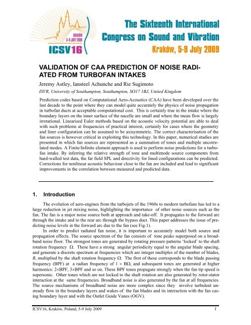
VALIDATION OF CAA PREDICTION OF NOISE RADI-<br />
ATED FROM TURBOFAN INTAKES<br />
Jeremy Astley, Iansteel Achunche and Rie Sugimoto<br />
ISVR, University <strong>of</strong> Southampton, Southampton, SO17 1BJ, United Kingdom<br />
Prediction codes based on Computational Aero-Acoustics (CAA) have been developed over the<br />
last decade to the point where they can model quite accurately the physics <strong>of</strong> <strong>noise</strong> propagation<br />
in turb<strong>of</strong>an ducts at acceptable computational cost. This is certainly true in the intake where the<br />
boundary layers on the inner surface <strong>of</strong> the nacelle are small and where the mean flow is largely<br />
irrotational. Linearised Euler methods based on the acoustic velocity potential are able to deal<br />
with such problems at frequencies <strong>of</strong> practical interest, certainly for cases where the geometry<br />
and liner configuration can be assumed to be axisymmetric. The correct characterisation <strong>of</strong> the<br />
fan sources is however critical in exploiting this technology. In this paper, numerical studies are<br />
presented in which fan sources are represented as a summation <strong>of</strong> tones and multiple uncorrel<strong>ated</strong><br />
modes. A Finite/Infinite element approach is used to perform <strong>noise</strong> <strong>prediction</strong>s for a turb<strong>of</strong>an<br />
intake. By inferring the relative strength <strong>of</strong> tone and multimode source components <strong>from</strong><br />
hard-walled test data, the far field SPL and directivity for lined configurations can be predicted.<br />
Corrections for nonlinear acoustic behaviour close to the fan are included and lead to significant<br />
improvements in the correlation between measured and predicted data.<br />
1. Introduction<br />
The evolution <strong>of</strong> aero-engines <strong>from</strong> the turbojets <strong>of</strong> the 1960s to modern turb<strong>of</strong>ans has led to a<br />
large reduction in jet mixing <strong>noise</strong>, highlighting the importance <strong>of</strong> other <strong>noise</strong> sources such as the<br />
fan. The fan is a major <strong>noise</strong> source both at approach and take-<strong>of</strong>f. It propagates to the forward arc<br />
through the intake and to the rear arc through the bypass duct. This paper addresses the issue <strong>of</strong> predicting<br />
<strong>noise</strong> levels in the forward arc due to the fan (see Fig.1).<br />
In order to predict <strong>radi</strong><strong>ated</strong> fan <strong>noise</strong>, it is important to accurately model both source and<br />
propagation effects. The source spectrum <strong>of</strong> the fan consists <strong>of</strong> tone peaks superposed on a broadband<br />
<strong>noise</strong> floor. The strongest tones are gener<strong>ated</strong> by rotating pressure patterns ‘locked’ to the shaft<br />
rotation frequency Ω. These have a strong angular periodicity equal to the angular blade spacing,<br />
and generate a discrete spectrum at frequencies which are integer multiples <strong>of</strong> the number <strong>of</strong> blades,<br />
B, multiplied by the shaft rotation frequency Ω. The first <strong>of</strong> these corresponds to the blade passing<br />
frequency (BPF) at a <strong>radi</strong>an frequency <strong>of</strong> 1 × BΩ, and subsequent tones are gener<strong>ated</strong> at higher<br />
harmonics: 2×BPF, 3×BPF and so on. These BPF tones propagate strongly when the fan tip speed is<br />
supersonic. Other tones which are not locked to the shaft rotation are also gener<strong>ated</strong> by rotor-stator<br />
interaction at the same frequencies. Broadband <strong>noise</strong> is also gener<strong>ated</strong> by the fan at all frequencies.<br />
The source mechanisms <strong>of</strong> broadband <strong>noise</strong> are more complex since they involve turbulent unsteady<br />
flow in the boundary layers and wakes <strong>of</strong> the fan blades and its interaction with the fan casing<br />
boundary layer and with the Outlet Guide Vanes (OGV).<br />
ICSV16, Kraków, Poland, 5-9 July 2009 1
16 th International Congress on Sound and Vibration, Kraków, Poland, 5–9 July 2009<br />
As fan <strong>noise</strong> propagates through the intake, it is attenu<strong>ated</strong> by acoustic liners in the nacelle<br />
and scattered by the intake geometry, by liner discontinuities and by the non-uniform mean flow.<br />
Scattering effects are most pronounced in the tones. Numerical <strong>prediction</strong>s <strong>of</strong> the far-field Sound<br />
Pressure Level (SPL) field shapes for a given source distribution are computationally challenging.<br />
The acoustic wavelengths are generally an order <strong>of</strong> magnitude smaller than the geometric scales,<br />
and methods are needed which exhibit low dispersion and low dissipation. Conventional low order<br />
CFD is unsuitable on both counts. Methods that have been applied to this problem include; Boundary<br />
Element (BE) methods 1 , Finite and Infinite Element (FE/IE) models 2 and Computational<br />
Aeroacoustics (CAA) methods based on the solution <strong>of</strong> the full or Linearised Euler Equations<br />
(LEE). BE and FE/IE models solve a convected wave equation in the frequency domain. They are<br />
applicable only when the mean flow is irrotational. More general CAA methods which are applied<br />
to the LEE do not suffer <strong>from</strong> this limitation. They are applied most effectively in the time-domain<br />
but this brings additional challenges such as controlling non-physical shear instablities and modelling<br />
the impedance <strong>of</strong> acoustic liners in the time-domain. The assumption <strong>of</strong> irrotational flow is<br />
however not a major limitation in the intake given that the mean flow originates in a region <strong>of</strong> uniform<br />
flow upstream <strong>of</strong> the nacelle and that the boundary layers on the inner surfaces <strong>of</strong> the nacelle<br />
are relatively small on a wavelength scale. FE/IE methods are therefore an attractive option for<br />
intake <strong>prediction</strong>s and are widely used for this purpose. In the case <strong>of</strong> axisymmetric problems (such<br />
as those presented in this paper) FE/IE <strong>prediction</strong>s <strong>of</strong> intake <strong>noise</strong> can be computed for an acceptable<br />
frequency range and for a complete set <strong>of</strong> sources in times which are acceptable for industrial<br />
application (minutes or hours rather than days or weeks <strong>of</strong> serial rather than parallel computation).<br />
One major limitation both <strong>of</strong> Helmholtz FE/IE methods and <strong>of</strong> more general CAA methods based<br />
on LEE is that they are unable to deal with non-linear propagation effects which can be significant<br />
close to the fan when the blade tip speed is supersonic. In the current article these will be dealt separately<br />
using a different technique.<br />
In this paper, <strong>prediction</strong>s are made by using ACTRAN/TM 3 , a commercial code developed<br />
by Free Field Technologies SA. ACTRAN/TM uses a Finite/Infinite Element approach 5,2 . In the<br />
current application, it is executed within a shell programme ANPRORAD, developed at ISVR<br />
within a collaborative partnership with IHI Corporation. Tone <strong>prediction</strong>s are presented at BPF for<br />
realistic hard-walled and lined <strong>intakes</strong>, and compared to data <strong>from</strong> a fan test rig. Broadband <strong>noise</strong><br />
<strong>prediction</strong>s have also been made, but these results are not presented here.<br />
The BPF tone source levels used in the <strong>prediction</strong> are calibr<strong>ated</strong> by using in-duct mode detection<br />
measurements. At supersonic fan tip speeds a non-linear propagation code ‘Frequency Domain<br />
Numerical Solution’ (FDNS) developed by McAlpine and Fisher 4 is used as a correction to the linear<br />
ANPRORAD/ACTRAN <strong>prediction</strong>s.<br />
2<br />
Forward arc <strong>noise</strong><br />
Intake liner<br />
Non-linear decay <strong>of</strong><br />
rotor-locked tones<br />
Fan<br />
Scattering by liners, internal geometry<br />
and non uniform mean flow<br />
OGV<br />
Figure 1. Propagation <strong>of</strong> fan <strong>noise</strong> through the intake and <strong>radi</strong>ation into the far-field.
16 th International Congress on Sound and Vibration, Kraków, Poland, 5–9 July 2009<br />
Baffle<br />
Duct intake<br />
Spinner<br />
2. The Prediction Scheme<br />
ANPRORAD is a shell program that generates and executes a sequence <strong>of</strong> ACTRAN/TM<br />
computations for an axisymmetric turb<strong>of</strong>an intake with subsonic mean flow. ANPRORAD reads<br />
key geometric data, mean flow data and frequency data and generates a sequence <strong>of</strong> finite element<br />
(FE) meshes for the intake and a surrounding near field region, each with an appropriate resolution<br />
for a given frequency range <strong>of</strong> interest. Fan source data is defined on the fan plane in terms <strong>of</strong> prescribed<br />
set <strong>of</strong> incident modal intensities for hard-walled annular duct modes and anechoic conditions<br />
are assumed for <strong>noise</strong> propagating back into the fan. Prior to the acoustic computation, the<br />
compressible Euler equations are solved within ANPRORAD to define the mean flow in the intake<br />
and in the surrounding region. A coarse version <strong>of</strong> the acoustic mesh is used and the results are interpol<strong>ated</strong><br />
onto the acoustic mesh for a sequence <strong>of</strong> ACTRAN/TM acoustic analyses at prescribed<br />
frequency intervals. A coarse low-frequency ANPRORAD FE mesh is shown in Fig. 2 for the rig<br />
geometry shown in Fig. 3. The ACTRAN model contains a conical baffle which is tre<strong>ated</strong> as an<br />
extended nacelle lip. The FE mesh itself is extended to the back <strong>of</strong> what would be the nacelle in a<br />
flight configuration, to model the anechoic nature <strong>of</strong> the chamber into which the test rig protrudes.<br />
The inner domain shown in Fig. 2 is discretised by quadratic elements giving fourth order accuracy<br />
in the usual sense. The outer region is modelled by a single layer <strong>of</strong> high order infinite elements<br />
which are compatibly matched to the FE mesh at the FE/IE interface. The acoustic pressure within<br />
each infinite element is modelled by an n th order multipole expansion. The order <strong>of</strong> the multipole<br />
expansion used for the results presented here is typically 15. The treatment <strong>of</strong> acoustic liners<br />
within ACTRAN/TM is based on a slip condition at the wall and continuity <strong>of</strong> pressure and particle<br />
displacement over an infinitely thin vortex sheet above the impedance surface. This is modelled by<br />
Eversman’s implementation <strong>of</strong> the Myers 6 boundary condition. In the far-field, acoustic pressure<br />
amplitude is computed on an arc with its centre point on the duct axis. This defines a field shape<br />
for the sound pressure level (SPL) which can be compared with measured SPL data.<br />
3. Experimental Set-up<br />
FE/IE interface<br />
Fan plane<br />
Figure 2. An example <strong>of</strong> a low-frequency ANPRORAD FE mesh for a fan rig intake incorporating the baffle<br />
as an extension <strong>of</strong> the nacelle intake geometry.<br />
Noise measurements were taken on the 1/3-scale model fan rig, shown in Fig. 3. The rig was<br />
mounted so that the intake <strong>radi</strong><strong>ated</strong> into an Anechoic Test Cell . The configuration tested had a cylindrical<br />
intake barrel, and a 24-bladed fan. The general set up is shown in Fig. 3. A ring <strong>of</strong> pressure<br />
transducers is loc<strong>ated</strong> at the entrance the lined intake barrel. Two intake configurations are<br />
considered: a hard-walled intake barrel with a hard-walled fan case, and a lined intake barrel with a<br />
lined fan case. Far field SPL measurements were taken at an array <strong>of</strong> far-field microphones loc<strong>ated</strong><br />
at the rig centreline height, between 0 and 120 degrees relative to the intake axis with a 5 degrees<br />
spacing.<br />
3
16 th International Congress on Sound and Vibration, Kraków, Poland, 5–9 July 2009<br />
4<br />
TCS<br />
Baffle<br />
Figure 3. Intake <strong>of</strong> 1/3 scale model fan rig with acoustic baffle and Turbulence Control Screen (TCS).<br />
4. Mode Detection Data<br />
Transducers ring Intake barrel<br />
Transition casing<br />
Fan case<br />
Cylindrical section<br />
The measured data obtained <strong>from</strong> the pressure transducers mounted in the mode detection ring<br />
are converted to wall sound pressure levels <strong>of</strong> the circumferential duct modes using the method dedescribed<br />
by Rademaker et al. 7 .<br />
5. Tone Predictions at the Blade Passing Frequency (BPF)<br />
Spinner<br />
Predictions at BPF were performed for the fan rig described above. Predictions <strong>of</strong> the far-field<br />
sound pressure level (SPL) were made for hard-walled and lined configurations at a number <strong>of</strong> fan<br />
speeds. The source is assumed to consist <strong>of</strong> a multimodal base and a single BPF tone at higher fan<br />
speeds. The distribution <strong>of</strong> acoustic power in the multimode source is modelled by assuming equal<br />
power per mode for all cut-on modes. When the fan tip speed is supersonic, an additional rotorlocked<br />
component is included which corresponds to the first <strong>radi</strong>al BPF tone for which (in this<br />
case) m = 24. All <strong>of</strong> the cut-on modes which are included in the mutimodal content, as well as the<br />
'm = 24' mode, are assumed to be uncorrel<strong>ated</strong>. At subsonic tip speeds (50% to 70% fan speed), the<br />
‘m = 24’ mode is cut-<strong>of</strong>f and the source model then consists only <strong>of</strong> the multimodal, equal power,<br />
component. Above 80% fan speed however, the ‘m = 24’ mode is cut-on and the fan source contains<br />
both contributions. In all cases and at all frequencies, far-field directivities are computed for<br />
each <strong>of</strong> the modes present at the fan plane, and these are summed in the far field as contributions<br />
<strong>from</strong> uncorrel<strong>ated</strong> sources. The sound pressure level is then calcul<strong>ated</strong> as;<br />
p 1<br />
SPL = 20. log10<br />
. , (1)<br />
2 pref<br />
where p 2 is the root mean square pressure and Pref is a reference pressure, 2.10 -5 Pa.<br />
Measured data are taken for the case <strong>of</strong> a hard (i.e. no liners) and a lined intake. The hardwalled<br />
case is used to calibrate the source model. Fig. 4 shows mode detection data for a hardwalled<br />
intake taken <strong>from</strong> the ring <strong>of</strong> transducers close to the outlet flare (see Fig. 3). The measured<br />
SPL on the wall is sampled at a frequency which corresponds, at each fan operating speed, to an<br />
'Engine Order' (EO) <strong>of</strong> 24, corresponding to BPF for a 24 bladed fan. At each fan speed the measured<br />
data is decomposed into components corresponding to each circumferential mode number m.<br />
Fan
16 th International Congress on Sound and Vibration, Kraków, Poland, 5–9 July 2009<br />
The results are shown as a contour plot for SPL versus circumferential order and fan speed. For fan<br />
speeds less than about 80% , the modal SPL is distributed fairly evenly over an expanding range <strong>of</strong><br />
azimuthal orders corresponding to the modes which are cut on at that condition. However, for fan<br />
speeds greater than 80% , the ‘m = 24’ mode can be seen to be strongly cut-on (in the upper 1/3 <strong>of</strong><br />
the figure). Fig. 5 shows a typical <strong>prediction</strong> at 80% fan speed <strong>of</strong> the overall far-field field shape<br />
plotted against angle <strong>from</strong> the forward axis <strong>of</strong> the engine. Contributions <strong>from</strong> the 'equal energy' portion<br />
<strong>of</strong> the source and <strong>from</strong> the m=24 tone are plotted separately and combined. Absolute levels <strong>of</strong><br />
both contributions are obtained <strong>from</strong> the calibration procedure described in the following section.<br />
Figure 4. Mode detection plot at 1 BPF showing the variation <strong>of</strong> sound pressure level with circumferential<br />
mode number and fan speed.<br />
Far-field SPL / dB<br />
10 dB<br />
Rotor-alone (m=24) contribution<br />
Multimodal contribution<br />
Total <strong>prediction</strong><br />
0 20 40 60 80 100 120<br />
Angle <strong>from</strong> intake axis / degrees<br />
Figure 5. Typical <strong>prediction</strong> <strong>of</strong> the overall far-field SPL field shape at 80% fan speed for a hard-walled intake.<br />
5.1 Calibrating Predictions to obtain Absolute Levels<br />
In order to compare the <strong>prediction</strong>s with measured data, the predicted levels for the multimodal<br />
content and the ‘m = 24’ content are calibr<strong>ated</strong> individually <strong>from</strong> mode detection measurements.<br />
The calibration is performed by computing an SPL <strong>prediction</strong> for each propagating mode at a grid<br />
point on the FE mesh which coincides with the location <strong>of</strong> the mode detection ring on the rig.<br />
5
16 th International Congress on Sound and Vibration, Kraków, Poland, 5–9 July 2009<br />
In the case where only a multimodal contribution is present, at 50% <strong>of</strong> maximum fan speed for<br />
example, the far-field SPL <strong>prediction</strong>s are calibr<strong>ated</strong> by using the difference between the predicted<br />
value <strong>of</strong> SPL at the grid point and the measured value <strong>of</strong> SPL at the same point. The measured<br />
value is obtained by adding the contributions <strong>from</strong> all the circumferential modes incoherently (see<br />
Fig. 6(a)).<br />
When tones are present, above 80% <strong>of</strong> the maximum fan speed, the far-field SPL <strong>prediction</strong><br />
is calibr<strong>ated</strong> by using the difference between the predicted wall SPL and the in-duct SPL measurement<br />
for the ‘m = 24’ mode as shown in Fig. 6(b). However, due to the high sound energy level in<br />
the rotor-locked ‘m = 24’ mode and the limited dynamic range (18 dB) <strong>of</strong> the mode detection ring,<br />
the measured multimodal content <strong>of</strong> the source at these speeds is unreliable and hence could not be<br />
used to calibrate the <strong>prediction</strong>s. An approximate approach was used to obtain absolute levels by<br />
adjusting the predicted far-field SPL directivity curves to match the measurements between 0 to 20<br />
degrees, where the multimodal content dominates over the ‘m = 24’ mode.<br />
6<br />
In-duct SPL / dB<br />
50% fan speed<br />
10 dB<br />
-80 -60 -40 -20 0 20 40 60 80<br />
Circumferential mode number, m<br />
Measurements<br />
In-duct SPL / dB<br />
80% fan speed<br />
-80 -60 -40 -20 0 20 40 60 80<br />
Circumferential mode number, m<br />
(a) (b)<br />
Figure 6 Mode detection plots at 50% and 80% fan speeds at BPF.<br />
10 dB<br />
Measurements<br />
5.2 Comparing BPF tone Predictions with Measurements<br />
The BPF tone <strong>prediction</strong>s at 50%, 60%, 70%, 80% and 90% fan speeds are shown in Fig. 7(a)<br />
to 7(e). Results are shown for the hard-walled and lined cases. The source strength obtained <strong>from</strong><br />
hard-walled data, is used for both <strong>prediction</strong>s. These comparisons generally show good agreement<br />
between measured and predicted data for fan speeds up to 80%. However at 90% fan speed (Fig.<br />
7(e)), ANPRORAD over-predicts the overall attenuation due to the liner. This results <strong>from</strong> an over<strong>prediction</strong><br />
by ANPRORAD <strong>of</strong> the attenuation <strong>of</strong> the ‘m = 24’ mode. It is quite possible that a similar<br />
over-predicted has occurred for the ‘m = 24’ mode at 80% fan speed, but in this case the overall<br />
directivity is domin<strong>ated</strong> by the multimode component and any over-<strong>prediction</strong> <strong>of</strong> the tone attenuation<br />
is lost below the 'floor' set by the multimode source. At 90% fan speed, however, the ‘m = 24’<br />
mode is less attenu<strong>ated</strong> and dominates in the measurements over the multimodal contribution at<br />
some angles in the measured data (Fig. 7(e)). An over-<strong>prediction</strong> <strong>of</strong> the attenuation <strong>of</strong> the ‘m = 24’<br />
mode therefore shows as a discrepancy with the measured data.<br />
5.3 The Effect <strong>of</strong> Non-linear Propagation and the presence <strong>of</strong> a Boundary Layer on<br />
the Attenuation <strong>of</strong> EO modes<br />
A non-linear Frequency Domain Numerical Solution (FDNS) model for EO tones, has been developed<br />
by McAlpine and Fisher 4 . This can be used to estimate the non-linear propagation <strong>of</strong> the rotor-alone<br />
pressure field in hard-walled and lined intake ducts. The basis <strong>of</strong> the FDNS approach is<br />
to model the rotor-alone pressure approximately by a one-dimensional irregular sawtooth pressure<br />
waveform and to include non-linear effects in this simple model. In this paper, decay rates for the<br />
1 st and 2 nd <strong>radi</strong>al modes <strong>of</strong> the rotor-locked ‘m=24’ tones have been obtained by using FDNS .
16 th International Congress on Sound and Vibration, Kraków, Poland, 5–9 July 2009<br />
While strictly speaking, FDNS assumes that only the first <strong>radi</strong>al order is present, decay rates for<br />
the 1 st and 2 nd <strong>radi</strong>al modes have been used in the current instance to obtain the FDNS estimate for<br />
the liner attenuation <strong>of</strong> the ‘m=24’ mode. It is assumed that the 1 st and 2 nd <strong>radi</strong>al modes have equal<br />
acoustic power. Fig. 8 shows the original over-<strong>prediction</strong> <strong>of</strong> liner attenuation, and that obtained<br />
when FDNS is used to adjust for non-linear effects. This significantly improves the general level <strong>of</strong><br />
agreement between the measured and predicted data. The difference in field shapes is not completely<br />
removed however, which may be due to the fact that the interaction between the first and<br />
second <strong>radi</strong>al modes is not modelled in either the linear ANPRORAD/ACTRAN solution nor the<br />
non-linear FDNS solution.<br />
Far-field SPL / dB<br />
5.4 Author names and affiliations<br />
Far-field SPL / dB<br />
10 dB<br />
Measured: Hardwall<br />
Predicted: Hardwall<br />
Measured: Lined<br />
Predicted: Lined<br />
0 20 40 60 80 100 120<br />
Angle <strong>from</strong> intake axis / degrees<br />
10 dB<br />
(a) 1 BPF, 50% fan speed<br />
Measured: Hard-walled<br />
Predicted: Hard-walled<br />
Measured: Lined<br />
Predicted: Lined<br />
0 20 40 60 80 100 120<br />
Angle <strong>from</strong> intake axis / degrees<br />
Far-field SPL / dB<br />
10 dB<br />
Far-field SPL / dB<br />
Far-field SPL / dB<br />
10 dB<br />
Measured: Hard-walled<br />
Predicted: Hard-walled<br />
Measured: Lined<br />
Predicted: Lined<br />
0 20 40 60 80 100 120<br />
Angle <strong>from</strong> intake axis / degrees<br />
10 dB<br />
Measured: Hard-walled<br />
Predicted: Hard-walled<br />
Measured: Lined<br />
Predicted: Lined<br />
0 20 40 60 80 100 120<br />
Angle <strong>from</strong> intake axis / degrees<br />
(b) 1 BPF, 60% fan speed<br />
Measured: Hard-walled<br />
Predicted: Hard-walled<br />
Measured: Lined<br />
Predicted: Lined<br />
0 20 40 60 80 100 120<br />
Angle <strong>from</strong> intake axis / degrees<br />
(c) 1 BPF, 70% fan speed (d) 1 BPF, 80% fan speed<br />
(e) 1 BPF, 90% fan speed<br />
Figure 7. Comparisons <strong>of</strong> measured and predicted far-field sound pressure levels for hard-walled and lined<br />
configurations.<br />
7
16 th International Congress on Sound and Vibration, Kraków, Poland, 5–9 July 2009<br />
6. Conclusions<br />
The authors draw the following conclusions <strong>from</strong> this study.<br />
• That accurate absolute <strong>prediction</strong>s <strong>of</strong> far field SPL and field shapes due to BPF tones are possible<br />
for realistic intake geometries and flows in the absence <strong>of</strong> liners provided that the source<br />
modal content is correctly specified.<br />
• That the <strong>prediction</strong> <strong>of</strong> attenu<strong>ated</strong> tone field shapes for lined <strong>intakes</strong> requires accurate impedance<br />
data and the inclusion at supersonic fan tip speeds <strong>of</strong> adjustments to account for non-linear<br />
propagation close to the fan.<br />
7. Acknowledgements<br />
This work is supported by Rolls-Royce plc and undertaken within the Rolls-Royce University<br />
Technology Centre in Gas Turbine Noise at the University <strong>of</strong> Southampton (UoS). The second author<br />
is supported also by the Engineering and Physical Sciences Research Council (EPSRC) within<br />
the Engineering Doctorate programme at the UoS. The authors are indebted to Dr. Alan McAlpine<br />
who provided modal decay rates for use in the FDNS calculation.<br />
REFERENCES<br />
1 S. Lidoine, H.T.S. Batard and A. Delnevo. “Acoustic <strong>radi</strong>ation modelling <strong>of</strong> aeroengine Intake,<br />
comparison between analytical and numerical methods,” AIAA paper 2001-2140, 2001.<br />
2 W. Eversman, “Mapped infinite wave envelope elements for acoustic <strong>radi</strong>ation in a uniformly<br />
moving medium”, J. Sound Vib., Vol. 224, 1999, pp. 665 – 87.<br />
3 ACTRAN 2006 User’s Manual, Free Field Technologies, Louvain-la-Neuve, Belgium, 2006.<br />
4 A. McAlpine and M.J. Fisher. On the <strong>prediction</strong> <strong>of</strong> “buzz-saw” <strong>noise</strong> in acoustically lined aeroengine<br />
inlet ducts. J. Sound Vib., 265(1):175-200, 2003.<br />
5<br />
R. J. Astley, G. J. Macaulay, J-P Coyette and L. Cremers. "Three-dimensional wave-envelope<br />
elements <strong>of</strong> variable order for acoustic <strong>radi</strong>ation and scattering. Part I. Formulation in the frequency<br />
domain". JASA, Vol 103(1) 1998, pp 49-63.<br />
6<br />
Myers, K.K., “On the acoustic boundary condition in the presence <strong>of</strong> flow,” J. Sound Vib., Vol.<br />
71, 1980, pp. 429 – 434.<br />
7<br />
E.R. Rademaker, P. Sijtsma, B.J. Tester. “Mode detection with an optimised array in model turb<strong>of</strong>an<br />
engine intake at varying shaft speeds”, AIAA paper 2001-2181, NLR-TP-2001-132, 2001.<br />
8<br />
Far-field SPL / dB<br />
10 dB<br />
Measured: Hard-walled<br />
Measured: Lined<br />
Predicted: Hard-walled<br />
Predicted: Lined<br />
Predicted: Lined, N.L. effects + 4% B.L.<br />
0 20 40 60 80 100 120<br />
Angle <strong>from</strong> intake axis / degrees<br />
Figure 8. Comparisons <strong>of</strong> measured and predicted far-field sound pressure levels for hard-walled and lined<br />
configurations showing the effect <strong>of</strong> a boundary layer and non-linear propagation on the attenuation <strong>of</strong> EO<br />
modes at 1BPF at 90% fan speed.
16 th International Congress on Sound and Vibration, Kraków, Poland, 5–9 July 2009<br />
9