
Create successful ePaper yourself
Turn your PDF publications into a flip-book with our unique Google optimized e-Paper software.
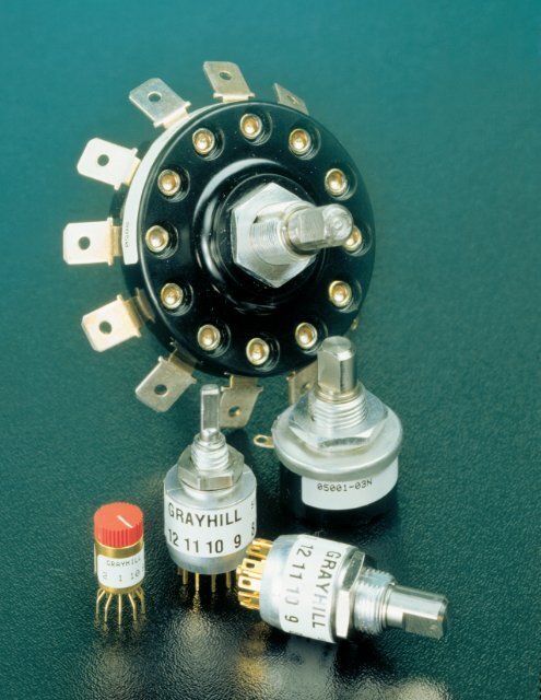
<strong>Rotary</strong> <strong>Rotary</strong> <strong>Switches</strong><br />
<strong>Switches</strong><br />
Grayhill, Grayhill, Inc. Inc. • • 561 561 Hillgrove Hillgrove Avenue Avenue • • LaGrange, LaGrange, Illinois Illinois 60525-5997 60525-5997 • • USA USA • • Phone: Phone: 708-354-1040 708-354-1040 • • Fax: Fax: 708-354-2820 708-354-2820 • • www.grayhill.com<br />
www.grayhill.com
Single Deck <strong>Rotary</strong> <strong>Switches</strong><br />
Contents: Single Deck <strong>Rotary</strong> <strong>Switches</strong><br />
SINGLE DECK<br />
ROTARY SWITCHES<br />
• Minimal Space Behind Panel<br />
.3" up to 1"+ In Diameter<br />
More Economical Choice Than<br />
Multi Deck <strong>Rotary</strong> <strong>Switches</strong><br />
High Quality, Enclosed <strong>Switches</strong><br />
Including Military Types<br />
Low Current, Wiping Contacts<br />
Grayhill, Inc. • 561 Hillgrove Avenue • LaGrange, Illinois 60525-5997 • USA • Phone: 708-354-1040 • Fax: 708-354-2820 • www.grayhill.com<br />
Page<br />
0.3" Diameter, 200 mA ...................................... Series 75 .........................2<br />
0.5" Diameter, 200 mA, .698" Behind Panel .... Series 50 & 51 .................4<br />
0.5" Diameter, 200 mA, .355" Behind Panel .... Series 56 ...................... 11<br />
2.0" Diameter, 15 Amp ...................................... Series 19 ...................... 15<br />
1.0" Diameter, 1 Amp, .470" Behind Panel ...... Series 5000 .................. 16<br />
1.0" Diameter, 1Amp, .580" Behind Panel ....... Series 24....................... 17<br />
<strong>Rotary</strong><br />
1<br />
<strong>Rotary</strong> <strong>Switches</strong>
<strong>Rotary</strong> <strong>Switches</strong><br />
SERIES 75<br />
0.3" Diameter, 200 mA<br />
FEATURES<br />
Small Size<br />
Flush, Shafted, or Knobbed Shaft<br />
DIMENSIONS In inches (and millimeters)<br />
Screwdriver Actuated<br />
.125 ± .005<br />
(3,18 ± 0,13)<br />
Shaft Actuated<br />
Integral Knob Actuated<br />
<strong>Rotary</strong><br />
2<br />
.298 ± .010<br />
(7,57 ± 0,25)<br />
DIA.<br />
3 4 5 6 7 8 9<br />
0 1 2<br />
SCREWDRIVER SLOT<br />
.032 ± .010<br />
(0,81 ± 0,25) DEEP<br />
.298 ± .010<br />
(7,57 ± 0,25)<br />
DIA.<br />
.298 ± .010<br />
(7,57 ± 0,25)<br />
DIA.<br />
Single Deck <strong>Rotary</strong> <strong>Switches</strong><br />
.020 ± .005<br />
(0,51 ± 0,13)<br />
108°<br />
.094 ± .015<br />
(2,39 ± 0,38)<br />
.203 ± .003<br />
(5,16 ± 0,08)<br />
ACROSS FLATS<br />
OF BUSHING<br />
C<br />
L OF<br />
POSITION 1<br />
.115 ± .010<br />
(2,92 ± 0,25)<br />
C<br />
L OF<br />
POSITION 1<br />
.489 ± .020<br />
(12,42 ± 0,51)<br />
.032 (0,81)<br />
REF.<br />
2 1 10 9<br />
All dimensions not shown and<br />
front views same as style BP.<br />
.109 ± .010<br />
(2,77 ± 0,25)<br />
SHOULDER<br />
DIAMETER<br />
Ø .031 ± .002<br />
(0,79 ± 0,05)<br />
TERMINAL<br />
Style AP DIAMETER<br />
Style AF<br />
Ø .015 ± .002<br />
All dimensions not shown and<br />
(0,38 ± 0,05)<br />
front views same as style AP.<br />
.375 ± .015<br />
(9,53 ± 0,38)<br />
.250<br />
± .015<br />
(6,35<br />
± 0,38)<br />
Ø .125 + .001/ - .002<br />
(3,18 + 0,03/ - 0,51)<br />
Style BP<br />
Style BF<br />
Style CP<br />
TERMINAL<br />
DIAMETER<br />
Ø .015 ± .002<br />
(0,38 ± 0,05)<br />
Style CF<br />
All dimensions not shown and<br />
front views same as style CP.<br />
Grayhill part number and date code marked on label.<br />
Customer part number marked on request.<br />
.500 ± .020<br />
(12,7 ± 0,51)<br />
.550 ± .020<br />
(13,97 ± 0,51)<br />
.539 ± .020<br />
(13,69 ± 0,51)<br />
Rear view shown<br />
on next page.<br />
Rear view shown<br />
on next page.<br />
Rear view shown<br />
on next page.<br />
Rear view shown<br />
on next page.<br />
Grayhill, Inc. • 561 Hillgrove Avenue • LaGrange, Illinois 60525-5997 • USA • Phone: 708-354-1040 • Fax: 708-354-2820 • www.grayhill.com<br />
.250<br />
± .015<br />
(6,35<br />
± 0,38)<br />
.489 ± .020<br />
(12,42 ± 0,51) .109 ± .010<br />
(2,77 ± 0,25)<br />
.032 (0,81)<br />
REF.<br />
2 1 10 9<br />
SHOULDER<br />
DIAMETER<br />
Ø .031 ± .002<br />
(0,76 ± 0,05)<br />
.032 (0,81)<br />
REF.<br />
1/4-32 UNF-2A<br />
THREAD<br />
2 1 10 9<br />
2 1 10 9<br />
2 1 10 9<br />
.539 ± .020<br />
(13,69 ± 0,51)<br />
TERMINAL<br />
DIAMETER<br />
Ø .015 ± .002<br />
(0,38 ± 0,05)<br />
2 1 10 9<br />
.109 ± .010<br />
(2,77 ± 0,25)<br />
.109 ± .010<br />
(2,77 ± 0,25)<br />
.109 ± .010<br />
(2,77 ± 0,25)<br />
SHOULDER<br />
DIAMETER<br />
Ø .031 ± .002<br />
(0,76 ± 0,05)<br />
.109 ± .010<br />
(2,77 ± 0,25)
CIRCUIT DIAGRAMS AND REAR VIEWS<br />
36° ANGLE<br />
OF THROW<br />
Switch is viewed<br />
from actuator end<br />
and shown in<br />
Position 1.<br />
Single Deck <strong>Rotary</strong> <strong>Switches</strong><br />
Style P<br />
COMMON LOCATION<br />
FOR A SINGLE POLE<br />
Style F<br />
Circle of terminal centers is<br />
SWITCH<br />
Circle of terminal centers is<br />
Ø .187 ± .010 (4,75 ± 0,25).<br />
.298 ± .010<br />
(7,57 ± 0,25)<br />
COMMON LOCATION<br />
FOR A TWO POLE<br />
SWITCH LOCATED ON<br />
.064 ± .010 (1,63 ± 0,25)<br />
DIA. CIRCLE OF CENTERS<br />
Ø .300 ± .010 (7,62 ± 0,25).<br />
Screwdriver Actuated<br />
36° ± 3°<br />
TYP.<br />
Integral Knob Actuated<br />
36° ± 3°<br />
TYP. Shaft Actuated<br />
Dot on actuator is next to contacting position of pole 1. Line on knob points to contacting position of pole 1. Shaft flat opposite point of contact of pole 1.<br />
6<br />
7<br />
8<br />
9<br />
10<br />
6<br />
7<br />
8<br />
9<br />
10<br />
6<br />
7<br />
5<br />
1 5<br />
1<br />
5<br />
1 5<br />
1<br />
5<br />
1 5<br />
1<br />
4<br />
3<br />
2 4<br />
3<br />
2<br />
4<br />
3<br />
2 4<br />
3<br />
2<br />
4<br />
3<br />
2 4<br />
3<br />
2<br />
ONE POLE TWO POLE ONE POLE TWO POLE ONE POLE TWO POLE<br />
SPECIFICATIONS<br />
Electrical Ratings<br />
Chart shown for non-shorting (break before<br />
make) contacts, resistive load.<br />
CURRENT<br />
(MILLIAMPS)<br />
300<br />
200<br />
100<br />
A<br />
B<br />
0<br />
0 5 10 15<br />
CYCLES x 1,000<br />
CURVE A: 220 Vac<br />
CURVE B: 115 Vac or 30 Vdc<br />
One cycle is 360° rotation and a return through<br />
all switch positions to the starting position. The<br />
data for the curve was measured at sea level,<br />
25°C and 68% relative humidity with the<br />
following limiting criteria:<br />
Contact Resistance: 50 milliohms maximum<br />
(15 milliohms initially).<br />
Insulation Resistance: 10,000 Mohms<br />
minimum between mutually insulated parts.<br />
CHOICES AND LIMITATIONS<br />
Grayhill, Inc. • 561 Hillgrove Avenue • LaGrange, Illinois 60525-5997 • USA • Phone: 708-354-1040 • Fax: 708-354-2820 • www.grayhill.com<br />
8<br />
9<br />
10<br />
6<br />
7<br />
8<br />
9<br />
10<br />
Voltage Breakdown: 500 Vac between mutually<br />
insulated parts.<br />
Life Expectancy: 10,000 cycles at 200 milliamps.<br />
One cycle is 360° rotation and a return through all<br />
switch positions to the starting position.<br />
Low Level Rating: Make and break a 50 mV, 1<br />
milliamp, resistive load for 10,000 cycles with a<br />
maximum contact resistance of 50 milliohms.<br />
Contact Grayhill for information if the life limiting<br />
criteria is more critical than those listed, if the<br />
required cycles of operation are greater than<br />
those listed, if a larger make and break current is<br />
required than the one listed for the desired number<br />
of cycles, or if elevated temperatures or reduced<br />
pressures are part of the operating environment.<br />
Materials and Finishes<br />
Switch Base: Diallyl per MIL-M-14<br />
Detent Cover and Detent Rotor in Styles AP,<br />
AF, BP, and BF: Phenolic per MIL-M-14<br />
Bushing: Brass, tin zinc plating<br />
6<br />
7<br />
8<br />
9<br />
10<br />
6<br />
7<br />
8<br />
9<br />
10<br />
Stop Pin: Stainless steel, passivated<br />
Detent Balls: Steel, nickel-plated<br />
Detent and Contact Springs: Tinned music<br />
wire<br />
Rotor Contact: Silver cad-oxide, gold-plated<br />
Terminals and Common: Brass, gold plate<br />
.00002" minimum thickness over silver plate<br />
.0003" minimum.<br />
Shaft in Style BF or BP: Zinc<br />
Integral Knob and Detent Rotor in Style CF or<br />
CP: Red Thermoplastic<br />
Mounting Hardware for Style BF or BP: One<br />
mounting nut .062" thick by .312" across flats<br />
and one external tooth lockwasher supplied<br />
with each switch. Mounting nut is brass, zinc<br />
plated and lockwasher is spring steel.<br />
Additional Characteristics<br />
Contact Type: Non-shorting, wiping contacts<br />
Terminals: <strong>Switches</strong> are provided with the full<br />
circle of terminals regardless of the number of<br />
active positions.<br />
Stop Strength: 8 ounce-inches minimum<br />
Style and Designation Number of Decks<br />
Ø 0.187 (4,75) Ø 0.300 (7,62) Angle Poles Non- Number of<br />
Circle of Term. Circle of Term. Of Throw Stops Terminal Per Deck Shorting Shorting Positions/Pole<br />
AP = Screwdriver AF = Screwdriver<br />
Actuated Actuated 36° Fixed Printed 1 Not 1 2 thru 10<br />
BP = Shaft Operated BF = Shaft Operated 2 Available 1 2 thru 5<br />
CP = Integral Knob CF = Integral Knob<br />
ORDERING INFORMATION<br />
Series<br />
Style: Letters from Choices and Limitations Chart<br />
Angle of Throw: 36° only<br />
75AP36–01–1–10N–C<br />
Stop Arrangement: The suffix C or F must be added to a<br />
one pole per deck switch to indicate continuous rotation (C) or fixed stop<br />
(F) between position 1 and position 10.<br />
Type of Contacts: N=Non-shorting only<br />
Positions per Pole: requires 02 positions as a minimum to<br />
maximum allowable dependent on the poles per deck<br />
Poles per Deck: 1 or 2 poles available<br />
Number of Decks: 1 deck only<br />
Available from your local Grayhill Distributor.<br />
For prices and discounts, contact a local Sales<br />
Office, an authorized local Distributor, or Grayhill.<br />
<strong>Rotary</strong><br />
3<br />
<strong>Rotary</strong> <strong>Switches</strong>
<strong>Rotary</strong> <strong>Switches</strong><br />
SERIES 50 SERIES 51<br />
0.5" Diameter, 200mA,<br />
.698" Behind Panel<br />
FEATURES<br />
Optional Complete Seal for<br />
PC Board Assembly and Cleaning<br />
Small 1/2" Diameter<br />
Choice of 22.5°, 30°, 36°, 45°, 60°<br />
and 90° Angles of Throw<br />
Up to 4 Poles on 1 Deck<br />
Up to 16 Positions Per Switch<br />
PC or Solder Lug Termination<br />
Positive Shaft Grounding for<br />
EMI/RFI Shielding<br />
DIMENSIONS In inches (and millimeters)<br />
PC Mount Style<br />
DIMENSION<br />
D<br />
Single Deck <strong>Rotary</strong> <strong>Switches</strong><br />
.203 ± .003<br />
(5,16 ± 0,08)<br />
ACROSS<br />
FLATS<br />
A<br />
POS. 1<br />
OPTIONAL<br />
PANEL SEAL<br />
GASKET<br />
.093 ± .005<br />
(2,36 ± 0,13)<br />
Angle of Angle Angle of Angle<br />
Throw A Throw A<br />
22.5° 101.25° 45° 112.5°<br />
30° 105° 60° 120°<br />
36° 108° 90° 135°<br />
Solder Lug Style<br />
<strong>Rotary</strong><br />
4<br />
Grayhill part number and date code<br />
marked on label. Customer part<br />
number marked on request. Military<br />
part number marked when required.<br />
.375±.015<br />
(9,53±0,38)<br />
.250±.015<br />
(6,35±0,38)<br />
.250±.015<br />
(6,35±0,38)<br />
Ø.125 + .001 - .002<br />
(3,18 + 0,03 - 0,05)<br />
Front view same as<br />
PC Mount style.<br />
.375±.015<br />
(9,53±0,38)<br />
.250±.015<br />
(6,35±0,38)<br />
Ø.125 +.001- .002<br />
(3,18 + 0,03 -0,05)<br />
GRAYHILL<br />
.250±.015<br />
(6,35±0,38)<br />
.125 ± .015<br />
(3,18 ± 0,38)<br />
9<br />
10<br />
1<br />
2<br />
1/4-28 UNF-2A<br />
THREAD<br />
.020 ± .003<br />
(0,51 ± 0,08)<br />
.062 ± .003<br />
(1,57 ± 0,08)<br />
.020 ± .004<br />
(0,51 ± 0,10)<br />
.171 ± .015<br />
(4,34 ± 0,38)<br />
.171 ± .015<br />
(4,34 ± 0,38)<br />
.125 (3,18)<br />
REF.<br />
TERMINALS ARE<br />
.016 ± .003 (0,41 ± 0,08) SQ.<br />
COMMON Ø .025 ± .002<br />
(0,64 ± 0,06) AND EXTEND<br />
TO SAME PLANE AS<br />
POSITION TERMINALS<br />
TERMINAL SEALANT<br />
IN STYLE T<br />
Ø .025 ± .002<br />
(0,64 ± 0,05)<br />
Grayhill, Inc. • 561 Hillgrove Avenue • LaGrange, Illinois 60525-5997 • USA • Phone: 708-354-1040 • Fax: 708-354-2820 • www.grayhill.com<br />
GRAYHILL<br />
.658±.015<br />
(16,71±0,38)<br />
.234±.015<br />
(5,94±0,38)<br />
.153±.015<br />
(3,89±0,38)<br />
TERMINAL<br />
SEALANT<br />
IN STYLE "T"<br />
10 9<br />
1<br />
2<br />
1/4-28 UNF-2A<br />
THREAD<br />
PC TERMINAL DETAIL<br />
All angles of throw, except 22.5°<br />
DIMENSION "B"<br />
.125±.015<br />
(3,18±0,38)<br />
TERMINAL<br />
SEALANT<br />
IN STYLE "T"<br />
Dimension Series 50 Series 51 Dimension Style T All Others All 22.5°<br />
D<br />
.500 ± .015<br />
(12,70 ± 0,38)<br />
.562 ± .015<br />
(14,27 ± 0,38)<br />
B<br />
.576 ± .015<br />
(14,63 ± 0,38)<br />
.537 ± .015<br />
(13,64 ± 0,38)<br />
.537 ± .015<br />
(13,64 ± 0,38)<br />
SOLDER LUG TERMINAL DETAIL<br />
All angles of throw, except 22.5°<br />
.064 ± .005<br />
(1,63 ± 0,13)<br />
.032 ± .004<br />
(0,81 ± 0,10)<br />
.064 ± .005<br />
(1,63 ± 0,13)<br />
.021 ± .004<br />
(0,53 ± 0,10)<br />
Side View<br />
All others as shown at left<br />
PC COMMON DETAIL<br />
All angles of throw, except 22.5°<br />
.020 ± .004<br />
(0,51 ± 0,10)<br />
.062 ± .004<br />
(1,57 ± 0,10)<br />
SOLDER LUG TERMINAL DETAIL 22.5°<br />
.016 ± .004<br />
(0,41 ± 0,10)<br />
.046 ± .004<br />
(1,17 ± 0,10)
CIRCUIT DIAGRAMS AND REAR VIEWS: Solder Lug and PC Mount<br />
11.25˚<br />
POS. 1<br />
22.5˚<br />
POS. 1<br />
POLE 1<br />
Rear View<br />
SOLDER LUG<br />
COMMON TERMINAL<br />
(1 POLE)<br />
.382 ± .015 (9,70 ± 0,13)<br />
DIAMETER CIRCLE OF<br />
TERMINAL CENTERS<br />
15˚<br />
POS. 1<br />
30˚<br />
DIM. A ±<br />
.005 (0,13)<br />
THREE POLES<br />
Dimension A, diameter circle of common centers,<br />
is .175 (4,45) for Solder Lug and .232 (5,89) for PC.<br />
18˚<br />
POS. 1<br />
36˚<br />
22.5˚<br />
POS. 1<br />
POS. 1<br />
.320 ± .015 (8,13 ± 0,38)<br />
DIAMETER CIRCLE OF<br />
TERMINAL CENTERS<br />
30˚<br />
45˚<br />
45˚<br />
POS. 1<br />
.156 ± .015<br />
(3,96 ± 0,13)<br />
LOCATION<br />
OF COMMONS<br />
2 POLES<br />
11.25˚<br />
POS. 1<br />
22.5˚<br />
PC MOUNT<br />
COMMON TERMINAL (1 POLE)<br />
.382 ± .005 (9,70 ± 0,13)<br />
DIAMETER CIRCLE OF<br />
TERMINAL CENTERS<br />
COMMON TERMINAL (1 POLE)<br />
.156 ± .005 (3,96 ± 0,13)<br />
.500 ± .015<br />
(12,7 ± 0,13)<br />
DIA. CIRCLE<br />
OF CENTERS<br />
Single Deck <strong>Rotary</strong> <strong>Switches</strong><br />
13<br />
11<br />
10<br />
9<br />
8<br />
7<br />
12<br />
C2<br />
.156 ± .015<br />
(3,96 ± 0,13)<br />
C1<br />
LOCATION<br />
OF COMMONS<br />
2 POLES<br />
COMMON TERMINAL<br />
(1 POLE)<br />
6<br />
5 4<br />
LOCATION OF COMMONS<br />
2 POLES<br />
.320 ± .015 (8,13 ± 0,38) DIAMETER<br />
CIRCLE OF TERMINAL CENTERS<br />
.125 ± .015<br />
(3,18 ± 0,38)<br />
LOCATION OF COMMONS<br />
2 POLES<br />
COMMON TERMINAL (1 POLE)<br />
.320 ± .015 (8,13 ± 0,38) DIAMETER<br />
CIRCLE OF TERMINAL CENTERS<br />
.125 ± .015<br />
(3,18 ± 0,38)<br />
LOCATION OF COMMONS<br />
2 POLES<br />
COMMON TERMINAL (1 POLE)<br />
.320 ± .015 (8,13 ± 0,38) DIAMETER<br />
CIRCLE OF TERMINAL CENTERS<br />
60˚<br />
90˚<br />
POS. 1<br />
POLE 1<br />
.125 ± .015<br />
(3,18 ± 0,38)<br />
COMMON TERMINAL (1 POLE)<br />
LOCATION OF COMMONS<br />
2 POLES<br />
LOCATION OF COMMONS<br />
2 POLES<br />
.125 ± .015<br />
(3,18 ± 0,38)<br />
FOUR POLES<br />
.175 ± .005<br />
(4,45 ± 0,13)<br />
DIAMETER<br />
CIRCLE OF<br />
COMMON<br />
CENTERS<br />
Circuit as Viewed From Shaft End<br />
ONE POLE<br />
ONE POLE<br />
THREE POLES<br />
ONE POLE<br />
ONE POLE<br />
ONE POLE<br />
ONE POLE<br />
TWO POLES<br />
TWO POLES<br />
FOUR POLES<br />
TWO POLES<br />
3 2<br />
TWO POLES<br />
2<br />
TWO POLES<br />
TWO POLES<br />
Grayhill, Inc. • 561 Hillgrove Avenue • LaGrange, Illinois 60525-5997 • USA • Phone: 708-354-1040 • Fax: 708-354-2820 • www.grayhill.com<br />
7<br />
6<br />
8<br />
5<br />
9 10<br />
4<br />
3<br />
14<br />
15<br />
16<br />
1<br />
2<br />
3<br />
11<br />
12<br />
1<br />
2<br />
9 10<br />
8 11<br />
7<br />
C3 12<br />
6<br />
C2<br />
C1 1<br />
5<br />
4 3<br />
2<br />
6<br />
5<br />
5<br />
4<br />
4<br />
3<br />
7<br />
4<br />
8<br />
3<br />
6 7<br />
3<br />
5<br />
2<br />
2<br />
3 4<br />
2<br />
9<br />
10<br />
1<br />
2<br />
1<br />
6<br />
1<br />
8<br />
1<br />
13<br />
11<br />
10<br />
9<br />
12<br />
8<br />
7<br />
6<br />
5<br />
7<br />
6<br />
8<br />
5<br />
9 10<br />
11<br />
C2 12<br />
C1 1<br />
2<br />
4 3<br />
9 10<br />
8 11<br />
7 C3<br />
C4 12<br />
6<br />
C2<br />
C1 1<br />
5<br />
4 3<br />
2<br />
6<br />
5<br />
5<br />
4<br />
4<br />
3<br />
7<br />
4<br />
C1<br />
8<br />
3<br />
C2<br />
6 7<br />
C1<br />
C1<br />
5<br />
C2<br />
C2<br />
3 4<br />
2<br />
C1<br />
4<br />
C2<br />
14<br />
15<br />
16<br />
1<br />
2<br />
3<br />
9<br />
10<br />
1<br />
2<br />
1<br />
8<br />
1<br />
6<br />
1<br />
22.5° Angle<br />
of Throw<br />
30° Angle<br />
of Throw<br />
36° Angle<br />
of Throw<br />
45° Angle<br />
of Throw<br />
60° Angle<br />
of Throw<br />
90° Angle<br />
of Throw<br />
<strong>Rotary</strong><br />
5<br />
<strong>Rotary</strong> <strong>Switches</strong>
<strong>Rotary</strong> <strong>Switches</strong><br />
SPECIFICATIONS<br />
Military Qualification<br />
The dimensions for qualified switches are the<br />
same as those indicated in the drawings of<br />
standard switches. <strong>Switches</strong> with standard<br />
variations, such as shaft and bushing length,<br />
which do not affect switch performance, can<br />
be marked as qualified product. Contact<br />
Grayhill for complete information on variations.<br />
36°, 45°, 60°, 90° (Series 50): The C and M<br />
style switches are qualified to MIL-S-3786/20.<br />
They include the following:<br />
Solder lug or PC terminals<br />
With or without panel seal<br />
Series 50 qualified switches may be ordered<br />
by the ‘M’ number or by the Grayhill part<br />
number.<br />
30° (Series 51): The C and M style switches<br />
are qualified to MIL-S-3786/35. They include<br />
the following:<br />
Solder lug or PC terminals<br />
With or without panel seal<br />
Series 51 qualified switches may be ordered<br />
by the ‘M’ number or by the Grayhill part<br />
number.<br />
SPECIFICATIONS: Other<br />
Additional Characteristics<br />
Contact Type and Forces: Shorting or nonshorting<br />
wiping contacts with over 80 grams of<br />
contact force.<br />
Shaft Flat Orientation: Flat opposite contacting<br />
position of pole number one (see circuit<br />
diagrams).<br />
Terminals: <strong>Switches</strong> have the full circle of<br />
terminals, regardless of number of active<br />
position.<br />
Stop Strength: 7.5 pound-inches minimum<br />
Rotational Torque: 8–24 ounce-inches,<br />
depending on the number of poles.<br />
PROCESS SEALED–Style T<br />
Switch can be mounted on PC board with other<br />
components and subjected to wave soldering<br />
and conventional board cleaning techniques.<br />
No secondary wiring or soldering is necessary.<br />
Bushing is o-ring sealed; epoxy potting seals<br />
the terminals and the rear of the switch. Designed<br />
for PC assembly, this sealing technique<br />
can also be applied to solder lug terminal<br />
switches. A bushing to panel seal can also be<br />
added to the process sealed versions. Military<br />
qualified versions are available, see ordering<br />
information.<br />
<strong>Rotary</strong><br />
6<br />
Single Deck <strong>Rotary</strong> <strong>Switches</strong><br />
Electrical Ratings<br />
Life Expectancy: With the limiting criteria stated<br />
here, the Series 50 and 51 with non-shorting<br />
contacts will switch the following loads at<br />
atmospheric and reduced pressures for 25,000<br />
cycles of operations. One cycle is 360° rotation<br />
clockwise and 360° return.<br />
At 85°C, atmospheric pressure<br />
200 mA, 28 Vdc resistive<br />
150 mA, 115 Vac resistive<br />
30 mA, 28 Vdc inductive<br />
100 mA, 28 Vdc lamp load<br />
75 mA, 220 Vac lamp load<br />
At 25°C, reduced pressure (70,000 feet)<br />
200 mA, 28 Vdc resistive<br />
150 mA, 115 Vac resistive<br />
75 mA, 220 Vac resistive<br />
Materials and Finishes<br />
Switch Base: Thermoset<br />
Detent Rotor: Nylon<br />
Shaft, Stop Blades, Stop Arm, Thrust washer,<br />
and Retaining Ring: Stainless steel<br />
Detent Balls: Steel, nickel-plated<br />
Bushing: Zinc, tin-zinc plated<br />
Detent and Contact Springs: Stainless steel<br />
Common Ring: Brass, gold-plated over silver<br />
plate.<br />
Terminals: Brass, gold-plated over silver plate<br />
and nickel plate<br />
Rotor Contact: Precious metal alloy, goldplated<br />
1/4" SHAFT: Style K<br />
.219<br />
±.004<br />
CIRCLE SHOWING<br />
DIMENSIONS OF<br />
HOLE TO BE CUT<br />
IN PANEL.<br />
0.208<br />
Contact Resistance: 20 milliohms maximum,<br />
(10 milliohms initially).<br />
Insulation Resistance: 1,000 Mohms<br />
minimum between mutually insulated parts.<br />
Voltage Breakdown: 600 Vac minimum<br />
between mutually insulated parts at standard<br />
atmospheric pressure.<br />
Life Expectancy: Listed for the voltage source<br />
and make and break current levels. Contact<br />
Grayhill for more information if any of the<br />
following is true: the life limiting criteria are<br />
more critical than those listed; longer operation<br />
is required; a larger make and break current is<br />
required; the operating environment includes<br />
elevated temperatures or reduced pressures.<br />
Contact Carry Rating: Switch will carry 6<br />
amperes continuously with a maximum<br />
contact temperature rise of 20°C.<br />
Panel Seal: Silicone rubber<br />
Shaft Seal: Fluorosilicone<br />
Mounting Nuts: Brass, tin-zinc plated<br />
Mounting Hardware: One mounting nut .089"<br />
thick by .375" across flats and one internal<br />
tooth lockwasher are supplied with the switch.<br />
Maximum Mounting Torque: 15in-lbs<br />
Ø0.254 Ø0.280<br />
Grayhill, Inc. • 561 Hillgrove Avenue • LaGrange, Illinois 60525-5997 • USA • Phone: 708-354-1040 • Fax: 708-354-2820 • www.grayhill.com<br />
.340<br />
±.005<br />
POS. 1<br />
.250<br />
±.015<br />
.250+.002<br />
-.001<br />
.250<br />
±.015<br />
.375<br />
±.015<br />
1/8"Shaft "E" Style "K" Style<br />
POS. 1<br />
3/8-32 UNEF-2A<br />
THREAD<br />
Ø0.380<br />
0.240 0.350<br />
POS. 1
SUGGESTED ADJUSTABLE STOP<br />
SUBSTITUTION GUIDE<br />
Fixed Adj. Stop Fixed Adj. Stop<br />
Stop Style Stop Style<br />
Style Equivalent Style Equivalent<br />
50A 50D 51A 51D<br />
50C 50CD 51C 51CD<br />
50CP 50CDP 51CP 51CDP<br />
50M 50CD* 51M 51CD*<br />
50MP 50CDP* 51MP 51CDP*<br />
50P 50DP 51P 51DP<br />
50S 50D* 51S 51D*<br />
50SP 50DP* 51SP 51DP*<br />
*Form fit and function equivalents, but not watertight sealed to<br />
the panel.<br />
SHAFT AND PANEL SEAL: Styles S and M<br />
SCREWDRIVER SLOTTED SHAFT: Style B<br />
.032±.005<br />
(0,81±0,13)<br />
METRIC SHAFT AND BUSHING: Style E<br />
6,0±0,08<br />
3,15<br />
±0,12<br />
"A"<br />
"A"<br />
SEAL<br />
.125±.015<br />
(3,18±0,38)<br />
.050±.005<br />
(1,27±0,13)<br />
9,53<br />
±0,38<br />
6,35<br />
±0,38)<br />
ADJUSTABLE STOPS: Style D<br />
Adjustable stops permit the user to set and<br />
reset the number of positions per poles. Shown<br />
in the diagram, a plastic washer can be removed<br />
to reveal slots at the base of the bushing. Stop<br />
blades can be inserted into the appropriate slots<br />
to limit switch rotation. Positions per pole<br />
configuration can thus be changed to meet the<br />
needs of the application. Dimensions are the<br />
same as the fixed stop version, when plastic<br />
washer is in place. Most desirable for prototype<br />
work. Readily available from local distributor.<br />
7,0<br />
±0,51<br />
4,0<br />
±0,03 M7 x 0,75<br />
Single Deck <strong>Rotary</strong> <strong>Switches</strong><br />
Shaft and panel seal switches<br />
are watertight to the panel. They<br />
are not totally process sealed<br />
like the Style “T”. Panel is sealed<br />
by a gasket at the base of the<br />
bushing. Shaft is sealed by an<br />
O-ring inside the bushing. After<br />
mounting, seals do not alter<br />
switch dimensions. See Style<br />
“S” (standard switches) and<br />
Style “M” (military switches) in<br />
the Choices and Limitations<br />
chart.<br />
Form, fit and function equivalent<br />
to standard shaft switches.<br />
The dimensions shown have<br />
evolved as the most popular for<br />
this type of switch. See Style “B”<br />
in the Choices and Limitations<br />
chart. Previous users may have<br />
ordered these switches by a<br />
non-descriptive part number<br />
containing a “Y”. Contact<br />
Grayhill, if in doubt about a<br />
cross-reference.<br />
Metric standard dimensions for<br />
the shaft and bushing are shown<br />
in the drawing. Other dimensions<br />
approximately the same as<br />
shown in dimensional drawing.<br />
Contact Grayhill for exact<br />
dimensions. See Style “E” in<br />
the Choices and Limitations<br />
chart.<br />
Plastic<br />
Washer Stop<br />
Blades<br />
Grayhill, Inc. • 561 Hillgrove Avenue • LaGrange, Illinois 60525-5997 • USA • Phone: 708-354-1040 • Fax: 708-354-2820 • www.grayhill.com<br />
Stop<br />
Blade<br />
Slots<br />
ACCESSORY: Non-Turn Washers<br />
.400<br />
± .005<br />
DIA.<br />
(10,16<br />
± 0,13)<br />
.250 ± .003<br />
(6,35 ± 0,08)<br />
.060 ± .001<br />
(1,52 ± 0,25)<br />
In Inches (and millimeters)<br />
90° ± 1°<br />
Dimensions are in millimeters<br />
.025<br />
± .001<br />
(0,64<br />
± 0,03)<br />
.015<br />
(0,38)<br />
RADIUS<br />
MAX.<br />
.125<br />
± .005<br />
(3,16<br />
± 0,13)<br />
Part No. 50J1066<br />
Cut round hole for the bushing and for the<br />
non-turn tab. Washer fits the double D<br />
bushing flats. Washer is sold only when<br />
accompanied by an order for a like number<br />
of switches. Washer is 302 stainless steel.<br />
11,13<br />
± 0,13<br />
DIA.<br />
5,08<br />
± 0,05<br />
C L<br />
1,57 ± 0,08<br />
90˚ ± 1˚<br />
0,64<br />
± 0,05<br />
.015<br />
(0,38)<br />
RADIUS<br />
MAX.<br />
2,36<br />
± 0,13<br />
Part No. 71J1103<br />
Designed to fit the double flatted bushing<br />
of the metric dimensioned bushing, this<br />
non-turn washer permits a round hole for<br />
the bushing and the tab while still preventing<br />
switch rotation. Washer is only sold<br />
when accompanied by a like number of<br />
switches. Washer is 302 stainless steel.<br />
0.375<br />
0.125<br />
0.187<br />
0.032<br />
Part No. 50J5140-4<br />
Designed to fit the single flatted bushing of<br />
the "K" style switches, this non-turn washer<br />
prevents switch rotation when using a full<br />
round hole in the panel. Washer is only sold<br />
when accompanied by a like number of<br />
switches. Washer is 302 stainless steel.<br />
<strong>Rotary</strong><br />
7<br />
<strong>Rotary</strong> <strong>Switches</strong>
<strong>Rotary</strong> <strong>Switches</strong><br />
Single Deck <strong>Rotary</strong> <strong>Switches</strong><br />
CHOICES AND LIMITATIONS: Series 50<br />
A = Standard, 1/8" Shaft<br />
B = Screwdriver Slot Shaft<br />
C = Military, Without Panel Seal<br />
D = Adjustable Stop (Adj. Stop)<br />
Standard Style<br />
Angle Number Number of Shorting or<br />
Style Choices 1 of of Positions Non-Shorting<br />
Series Std., 1/8" Shaft 1/4" Shaft Metric, 4mm Shaft Terminals Throw Poles Per Pole Contacts<br />
50<br />
Military Style<br />
A<br />
AT<br />
B<br />
BS<br />
BST<br />
BT<br />
D<br />
S<br />
ST<br />
BP<br />
BPT<br />
BSP<br />
BSPT<br />
DP<br />
P<br />
PT<br />
SP<br />
SPT<br />
K<br />
KS<br />
KST<br />
KT<br />
KB<br />
KBS<br />
KBST<br />
KT<br />
KP<br />
KPT<br />
KSP<br />
KSPT<br />
KBP<br />
KBSP<br />
KBSPT<br />
KBT<br />
E = Metric, 4mm Shaft<br />
K = 1/4" Shaft<br />
M = Military<br />
E<br />
ES<br />
EST<br />
ET<br />
EB<br />
EBS<br />
EBST<br />
EBT<br />
EP<br />
EPT<br />
ESP<br />
ESPT<br />
EBP<br />
EBSP<br />
KBSPT<br />
EBT<br />
Solder<br />
Lug<br />
PC Mount<br />
Grayhill, Inc. • 561 Hillgrove Avenue • LaGrange, Illinois 60525-5997 • USA • Phone: 708-354-1040 • Fax: 708-354-2820 • www.grayhill.com<br />
36°<br />
45°<br />
60°<br />
90°<br />
36°<br />
45°<br />
60°<br />
90°<br />
P = PC Mount Terminals<br />
S = Shaft/Panel Seal (S/P Seal)<br />
T = Process Sealed<br />
1 02 thru 10 N or S<br />
2 02 thru 05 N or S<br />
1 02 thru 08 N<br />
2 02 thru 04 N<br />
1 02 thru 06 N<br />
2 02 or 03 N<br />
1 02 thru 04 N<br />
2 02 N<br />
1 02 thru 10 N or S<br />
2 02 thru 05 N or S<br />
1 02 thru 08 N<br />
2 02 thru 04 N<br />
1 02 thru 06 N<br />
2 02 or 03 N<br />
1 02 thru 04 N<br />
2 02 N<br />
Angle Number Number of Shorting or<br />
Style Choices of of Positions Non-Shorting<br />
Series Std., 1/8" Shaft 1/4" Shaft Metric, 4mm Shaft Terminals Throw Poles Per Pole Contacts<br />
50<br />
<strong>Rotary</strong><br />
8<br />
C<br />
CB<br />
CBT<br />
CD<br />
CT<br />
M<br />
MB<br />
MBT<br />
MT<br />
CBP<br />
CBPT<br />
CDP<br />
CP<br />
CPT<br />
MBP<br />
MBPT<br />
MP<br />
MPT<br />
KM<br />
KMB<br />
KMBT<br />
KMT<br />
KMBP<br />
KMBPT<br />
KMP<br />
KMPT<br />
EM<br />
EMB<br />
EMBT<br />
EMT<br />
EMBP<br />
EMBPT<br />
EMP<br />
EMPT<br />
Solder<br />
Lug<br />
PC Mount<br />
36°<br />
45°<br />
60°<br />
90°<br />
36°<br />
45°<br />
60°<br />
90°<br />
1 02 thru 10 N or S<br />
2 02 thru 05 N or S<br />
1 02 thru 08 N<br />
2 02 thru 04 N<br />
1 02 thru 06 N<br />
2 02 or 03 N<br />
1 02 thru 04 N<br />
2 02 N<br />
1 02 thru 10 N or S<br />
2 02 thru 05 N or S<br />
1 02 thru 08 N<br />
2 02 thru 04 N<br />
1 02 thru 06 N<br />
2 02 or 03 N<br />
1 02 thru 04 N<br />
2 02 N
CHOICES AND LIMITATIONS: Series 51<br />
A = Standard, 1/8" Shaft<br />
B = Screwdriver Slot Shaft<br />
C = Military, Without Panel Seal<br />
D = Adjustable Stop (Adj. Stop)<br />
Standard Style<br />
E = Metric, 4mm Shaft<br />
K = 1/4" Shaft<br />
M = Military<br />
Single Deck <strong>Rotary</strong> <strong>Switches</strong><br />
P = PC Mount Terminals<br />
S = Shaft/Panel Seal (S/P Seal)<br />
T = Process Sealed<br />
Angle Number Number of Shorting or<br />
Style Choices 1 of of Positions Non-Shorting<br />
Series Std., 1/8" Shaft 1/4" Shaft Metric, 4mm Shaft 1 Terminals Throw Poles Per Pole Contacts<br />
51<br />
Military Style<br />
Angle Number Number of Shorting or<br />
Style Choices of of Positions Non-Shorting<br />
Series Std., 1/8" Shaft 1/4" Shaft Metric, 4mm Shaft Terminals Throw Poles Per Pole Contacts<br />
51<br />
A AT<br />
B BT<br />
S ST<br />
BS BST<br />
A<br />
AT<br />
B<br />
BS<br />
BST<br />
BT<br />
D<br />
S<br />
ST<br />
P PT<br />
BP BPT<br />
SP SPT<br />
BSP BSPT<br />
BP<br />
BPT<br />
BSP<br />
BSPT<br />
DP<br />
P<br />
PT<br />
SP<br />
SPT<br />
C<br />
CB<br />
CBT<br />
CD<br />
CT<br />
M<br />
MB<br />
MBT<br />
MT<br />
CBP<br />
CBPT<br />
CDP<br />
CP<br />
CPT<br />
MBP<br />
MBPT<br />
MP<br />
MPT<br />
SEE BELOW SEE BELOW<br />
K<br />
KS<br />
KST<br />
KT<br />
KM<br />
KMB<br />
KMBT<br />
KMT<br />
KMBP<br />
KMBPT<br />
KMP<br />
KMPT<br />
E<br />
ES<br />
EST<br />
ET<br />
SEE BELOW SEE BELOW<br />
KP<br />
KPT<br />
KSP<br />
KSPT<br />
EP<br />
EPT<br />
ESP<br />
ESPT<br />
EM<br />
EMB<br />
EMBT<br />
EMT<br />
EMBP<br />
EMBPT<br />
EMP<br />
EMPT<br />
1 Contact Grayhill if 1/4" or metric shaft required with a 22.5° angle of throw.<br />
Grayhill, Inc. • 561 Hillgrove Avenue • LaGrange, Illinois 60525-5997 • USA • Phone: 708-354-1040 • Fax: 708-354-2820 • www.grayhill.com<br />
Solder<br />
Lug<br />
Solder<br />
Lug<br />
PC Mount<br />
PC Mount<br />
Solder<br />
Lug<br />
PC Mount<br />
22.5°<br />
30°<br />
22.5°<br />
30°<br />
30°<br />
30°<br />
1 02 thru 16 N or S<br />
2 02 thru 08 N or S<br />
1 02 thru 12 N or S<br />
2 02 thru 06 N or S<br />
3 02 thru 04 N or S<br />
4 02 or 03 N or S<br />
1 02 thru 16 N or S<br />
2 02 thru 08 N or S<br />
1 02 thru 12 N or S<br />
2 02 thru 06 N or S<br />
3 02 thru 04 N or S<br />
4 02 or 03 N or S<br />
1 02 thru 12 N or S<br />
2 02 thru 06 N or S<br />
3 02 thru 04 N or S<br />
4 02 or 03 N or S<br />
1 02 thru 12 N or S<br />
2 02 thru 06 N or S<br />
3 02 thru 04 N or S<br />
4 02 or 03 N or S<br />
<strong>Rotary</strong><br />
9<br />
<strong>Rotary</strong> <strong>Switches</strong>
<strong>Rotary</strong> <strong>Switches</strong><br />
ADDITIONAL FEATURES<br />
Economy keylock switch, isolated position,<br />
spring return, and coded switches are available<br />
in similar series. See Keylock and Special<br />
Function <strong>Rotary</strong> Switch sections.<br />
Available from your local Grayhill Distributor.<br />
For prices and discounts, contact a local Sales<br />
Office, an authorized local Distributor, or Grayhill.<br />
Single Deck <strong>Rotary</strong> <strong>Switches</strong><br />
ORDERING INFORMATION: Series 50<br />
50AT36–01–1–10N–F<br />
ORDERING INFORMATION: Series 51<br />
51SPT30–01–1–12S–F<br />
Series: Series 50 (36°, 45°, 60°, or 90°)<br />
Style*: Letters from Choices Chart<br />
Angle of Throw: 36, 45, 60, or 90<br />
Stop Arrangement: Needed only with 1 pole switches with<br />
maximum positions. Leave blank for continuous rotation;<br />
add F for fixed stop.<br />
Type of Contacts: N = Non-shorting, S = Shorting<br />
Positions Per Pole: 02 as a minimum to the maximum allowable<br />
for the angle of throw and the number of poles per the Choices Chart.<br />
Use Letters AJ in this location if adjustable stop switch is ordered.<br />
Poles per Deck: See chart<br />
Number of Decks: 01 only<br />
* All rotary switches that are required to have military designated markings and testing adhering to MIL-3786 are to be ordered by specifying<br />
the military part number identified on the appropriate slash sheet.<br />
Series: Series 51 (30°; 22.5°)<br />
Style*: Letters from Choices Chart<br />
Angle of Throw: Use 22 (for 22.5°), 30<br />
Stop Arrangement: Needed only with 1 pole switches with<br />
maximum positions. Leave blank for continuous rotation;<br />
add F for fixed stop.<br />
Type of Contacts: N = Non-shorting, S = Shorting<br />
Positions Per Pole: 02 as a minimum to the maximum allowable<br />
for the angle of throw and the number of poles per the Choices Chart.<br />
Use Letters AJ in this location if adjustable stop switch is ordered.<br />
Poles per Deck: See chart<br />
Number of Decks: 01 only<br />
* All rotary switches that are required to have military designated markings and testing adhering to MIL-3786 are to be ordered by specifying<br />
the military part number identified on the appropriate slash sheet.<br />
<strong>Rotary</strong><br />
10<br />
Grayhill, Inc. • 561 Hillgrove Avenue • LaGrange, Illinois 60525-5997 • USA • Phone: 708-354-1040 • Fax: 708-354-2820 • www.grayhill.com
SERIES 56<br />
0.5" Diameter, 200mA,<br />
.355" Behind Panel<br />
FEATURES<br />
Requires Minimum Distance Behind<br />
the Panel<br />
Adjustable Stop Types Provide<br />
Prototypes Immediately<br />
Industrial Quality, Economically<br />
Priced<br />
RoHS Compliant<br />
DIMENSIONS In inches (and millimeters)<br />
PC Mount Style<br />
.500<br />
Ø<br />
± .015<br />
(12,70<br />
± 0,25)<br />
Solder Lug Style<br />
.500<br />
Ø<br />
± .015<br />
(12,70<br />
± 0,38)<br />
.094 ± .010<br />
(2,39 ± 0,25)<br />
ANGLE OF ANGLE<br />
THROW A<br />
30° 105°<br />
36° 108°<br />
ANGLE OF ANGLE<br />
THROW A<br />
30° 105°<br />
36° 108°<br />
.203 ± .003<br />
(5,16 ± 0,08)<br />
ACROSS<br />
BUSHING<br />
FLATS<br />
A<br />
.094 ± .010<br />
(2,39 ± 0,25)<br />
.203 ± .003<br />
(5,16 ± 0,08)<br />
ACROSS<br />
BUSHING<br />
FLATS<br />
A<br />
POS. 1<br />
POS. 1<br />
.375 ± .015<br />
(9,53 ± 0,38)<br />
.250 ± .015<br />
(6,35 ± 0,38)<br />
.375 ± .015<br />
(9,53 ± 0,38)<br />
.250 ± .015<br />
(6,35 ± 0,38)<br />
Ø .125 ± .002<br />
(3,18 ± 0,06)<br />
Ø .125 ± .002<br />
(3,18 ± 0,06)<br />
.250 ± .015<br />
(6,35 ± 0,38)<br />
.250 ± .015<br />
(6,35 ± 0,38)<br />
Single Deck <strong>Rotary</strong> <strong>Switches</strong><br />
FOR REAR<br />
VIEWS, SEE<br />
FOLLOWING<br />
PAGE.<br />
FOR REAR<br />
VIEWS, SEE<br />
FOLLOWING<br />
PAGE.<br />
SOLDER LUG COMMON<br />
Grayhill, Inc. • 561 Hillgrove Avenue • LaGrange, Illinois 60525-5997 • USA • Phone: 708-354-1040 • Fax: 708-354-2820 • www.grayhill.com<br />
GRAYHILL<br />
2 1 10 9<br />
.377<br />
± .020<br />
(9,58<br />
± 0,51)<br />
GRAYHILL<br />
2 1 10 9<br />
1/4-28 UNEF-2A<br />
THREAD<br />
Grayhill part number and date code marked on label.<br />
Customer part number marked on request.<br />
1/4-28 UNF-2A<br />
THREAD<br />
Grayhill part number and date code marked on label.<br />
Customer part number marked on request.<br />
.110<br />
± .015<br />
(2,79<br />
± 0,38)<br />
.480 ± .020<br />
(12,19 ± 0,51)<br />
.125 ± .015<br />
(3,18 ± 0,38)<br />
.110 ± .015<br />
(2,79 ± 0,38)<br />
.110 ± .015<br />
(2,79 ± 0,38)<br />
PC TERMINAL DETAIL<br />
.016 ± .004 SQ.<br />
(0,4 ± 0,10)<br />
PC COMMON<br />
Ø .025 ± .002<br />
(0,64 ± 0,05)<br />
SOLDER LUG TERMINAL DETAIL<br />
.063 ± .005<br />
(1,60 ± 0,13)<br />
.020 ± .004<br />
(0,51 ± 0,10)<br />
.125 ± .015<br />
(3,18 ± 0,38)<br />
.016 ± .004<br />
(0,4 ± 0,10)<br />
.046 ± .004<br />
(1,2 ± 0,10)<br />
.016 ± .004<br />
(0,41 ± 0,10)<br />
.046 ± .004<br />
(1,17 ± 0,10)<br />
Ø .062 ± .002<br />
(1,58 ± 0,51)<br />
<strong>Rotary</strong><br />
11<br />
<strong>Rotary</strong> <strong>Switches</strong>
<strong>Rotary</strong> <strong>Switches</strong><br />
Single Deck <strong>Rotary</strong> <strong>Switches</strong><br />
CIRCUIT DIAGRAMS AND REAR VIEWS: PC Mountable AND Solder Lug Terminals<br />
15°<br />
POS. 1<br />
30° TYP.<br />
18°<br />
POS. 1<br />
36° TYP.<br />
COMMON LOCATION<br />
FOR 1 POLE SWITCH<br />
Rear View Circuit as Viewed From Shaft End<br />
.366 ± .015<br />
(9,30 ± 0,38)<br />
DIA. CIRCLE<br />
OF CENTERS<br />
COMMON LOCATION<br />
FOR 1 POLE SWITCH<br />
.190 ± .015 (4,83 ± 0,38)<br />
DIA. CIRCLE OF CENTERS<br />
(PC MOUNT AND<br />
SOLDER LUG)<br />
COMMON LOCATION<br />
FOR 2 POLE SWITCH<br />
.340 ± .015<br />
(8,64 ± 0,38) DIA.<br />
CIRCLE OF CENTERS<br />
DIMENSION A<br />
DIA. CIRCLE OF CENTERS<br />
COMMON LOCATION<br />
FOR 2 POLE SWITCH<br />
SPECIFICATIONS<br />
Electrical Ratings<br />
Chart shown for non-shorting (break before make)<br />
contacts, resistive load.<br />
CURRENT - MILLIAMPS<br />
300<br />
200<br />
100<br />
0<br />
0 10 20 30<br />
CYCLES x 1000<br />
115 Vac 0r 30 Vdc<br />
One cycle is 360° rotation clockwise and 360°<br />
return. The data for the curve was measured at<br />
sea level, 25°C and 68% relative humidity with<br />
the life limiting criteria which follows.<br />
Contact Resistance: 100 milliohms maximum,<br />
(15 milliohms initially).<br />
Insulation Resistance: 10,000 Mohms<br />
minimum between mutually insulated parts<br />
(50,000 Mohms initially).<br />
Voltage Breakdown: 600 Vac minimum<br />
between mutually insulated parts at standard<br />
atmospheric pressure.<br />
Life Expectancy: As determined from the loadlife<br />
curve for the current to be switched. Contact<br />
GRAYHILL for more information if any of the<br />
following is true: the life limiting criteria are more<br />
<strong>Rotary</strong><br />
12<br />
15°<br />
POS. 1<br />
30° TYP.<br />
PC Mount Solder Lug<br />
Dimension Terminals Terminals<br />
A .184 ± .015 .126 ± .015<br />
(4,67 ± 0,38) (3,20 ± 0,38)<br />
.366 ± .015<br />
(9,30 ± 0,38)<br />
DIA. CIRCLE<br />
OF CENTERS<br />
.190 ± .015 (4,83 ± 0,38)<br />
DIA. CIRCLE OF CENTERS<br />
(PC MOUNT AND<br />
SOLDER LUG)<br />
critical than those listed; longer operation is<br />
required; a larger make and break current is<br />
required; the operating environment includes<br />
elevated temperatures or reduced pressures.<br />
Contact Carry Rating: Switch will carry 6<br />
amperes continuously with a maximum<br />
contact temperature rise of 20°C.<br />
Additional Characteristics<br />
Contact Type and Forces: Shorting or nonshorting<br />
wiping contacts with over 25 grams of<br />
contact force.<br />
Shaft Flat Orientation: Flat opposite contacting<br />
position of pole number one (see circuit diagrams).<br />
Terminals: <strong>Switches</strong> have the full circle of<br />
terminals, regardless of number of active positions.<br />
Stop Strength: 7.5 lb-in. minimum<br />
Rotational Torque: 3.5 to 9 oz-in. (21-53 mNm),<br />
depending on the number of poles.<br />
Bushing Mounting: Required for switches with<br />
stops, and recommended for switches without<br />
stops.<br />
Meets MIL-S-3786 for:<br />
High and medium shock; Vibration (10 to 2,000<br />
Hz); Thermal shock (-65° to 85 ° C); Salt spray;<br />
Explosion; Stop strength (7.5 in-lbs. minimum<br />
(.85 N-m); Terminal strength; Sealed styles<br />
withstand water pressure of 15 PSI minimum<br />
(103 KPa) without leakage.<br />
TWO POLES<br />
ONE POLE<br />
6<br />
1<br />
5<br />
2<br />
4 3<br />
ONE POLE<br />
FOUR POLES<br />
TWO POLES<br />
30° Angle<br />
of Throw<br />
36° Angle<br />
of Throw<br />
Grayhill, Inc. • 561 Hillgrove Avenue • LaGrange, Illinois 60525-5997 • USA • Phone: 708-354-1040 • Fax: 708-354-2820 • www.grayhill.com<br />
7<br />
6<br />
6<br />
5<br />
8<br />
5<br />
7<br />
4<br />
9 10<br />
11<br />
C2 12<br />
C1 1<br />
2<br />
4 3<br />
8<br />
3<br />
9<br />
10<br />
1<br />
2<br />
7<br />
8<br />
9 10<br />
11<br />
12<br />
9 10<br />
8 11<br />
7 C3<br />
C4 12<br />
6<br />
C2<br />
C1 1<br />
5<br />
4 3<br />
2<br />
6<br />
5<br />
7<br />
4<br />
C1<br />
8<br />
3<br />
C2<br />
9<br />
10<br />
1<br />
2<br />
Materials and Finishes<br />
Housing: Zinc die cast, tin zinc plated<br />
Mounting Nut: Brass, tin zinc plated<br />
Lockwasher: Spring steel, zinc plated<br />
Panel Seal: Silicone rubber<br />
Shaft and Stop Arm: Zinc die cast<br />
Retaining Ring: 302 Stainless steel, passivated<br />
Shaft Seal: Silicone rubber<br />
Stop Pins: 303 Stainless steel, passivated<br />
Detent Rotor: Molded thermoplastic<br />
Detent Spring: Tinned music wire<br />
Detent Balls: Steel, nickel-plated<br />
Contact Spring: Stainless steel, passivated<br />
Rotor Contact: Brass, silver over nickel plate<br />
Common Ring: Brass, gold over silver over<br />
nickel plate<br />
Terminals: Brass, gold over silver over nickel<br />
plate<br />
Switch Base: Molded thermoset plastic<br />
Mounting Hardware: One mounting nut .089"<br />
thick by .375" across flats and one internal tooth<br />
lockwasher are supplied with the switch.
SHAFT AND PANEL SEAL: Style S<br />
SCREWDRIVER SLOTTED SHAFT: Option<br />
.032 ± .005<br />
(0,81 ± 0,13)<br />
ADJUSTABLE STOP SWITCHES<br />
REMOVABLE<br />
STICKER FOR<br />
ADJUSTMENT<br />
OF STOPS<br />
SEAL<br />
Two stop pins and an adhesive backed sticker<br />
or seal washer are provided. Sticker is<br />
temporarily removed to locate stop pins as<br />
A<br />
ADJUSTABLE<br />
STOP PINS<br />
.125 ± .015<br />
(3,18 ± 0,38)<br />
.050 ± .005<br />
(1,27 ± 0,13)<br />
SUGGESTED ADJUSTABLE STOP SUBSTITUTION GUIDE<br />
ADJUSTABLE<br />
STOP PINS<br />
REMOVABLE<br />
SEAL WASHER<br />
FOR ADJUSTMENT<br />
OF STOPS<br />
Fixed Stop Adjustable Stop Fixed Stop Adjustable Stop<br />
Style Style Equivalent Style Style Equivalent<br />
56A 56D 56B 56BD<br />
56S 56SD 56BS 56BSD<br />
56P 56DP 56BP 56BDP<br />
56SP 56SDP 56BSP 56BSDP<br />
Single Deck <strong>Rotary</strong> <strong>Switches</strong><br />
Panel is sealed by a flat rubber<br />
seal washer at the base of bushing.<br />
Shaft is sealed by an Oring<br />
inside the bushing. After<br />
the switch is mounted, seals do<br />
not alter the dimensions of the<br />
unsealed style.<br />
Series 56 rotary switches are<br />
available with a screwdriver<br />
slotted shaft with dimensions<br />
as shown. Available in the<br />
styles, angles of throw and pole/<br />
positions combinations shown<br />
in the choice and limitations<br />
chart.<br />
desired to limit the shaft rotation. All dimensions<br />
are identical to the fixed stop switch counterpart.<br />
ACCESSORY: Non-Turn Washer<br />
.250 ± .003<br />
(6,35 ± 0,08)<br />
.060 ± .001<br />
(1,52 ± 0,25)<br />
In Inches (and millimeters)<br />
Part No. 50J1066<br />
Cut round hole for the bushing and for the<br />
non-turn tab. Washer fits the double D<br />
bushing flats. Washer is sold only when<br />
accompanied by an order for a like number<br />
of switches. Washer is 302 stainless steel.<br />
Grayhill, Inc. • 561 Hillgrove Avenue • LaGrange, Illinois 60525-5997 • USA • Phone: 708-354-1040 • Fax: 708-354-2820 • www.grayhill.com<br />
.400<br />
± .005<br />
DIA.<br />
(10,16<br />
± 0,13)<br />
90° ± 1°<br />
Shaft and<br />
Panel Seal<br />
Screwdriver<br />
Slotted Shaft<br />
Adjustable<br />
Stop<br />
.025<br />
± .001<br />
(0,64<br />
± 0,03)<br />
.015<br />
(0,38)<br />
RADIUS<br />
MAX.<br />
.125<br />
± .005<br />
(3,16<br />
± 0,13)<br />
<strong>Rotary</strong><br />
13<br />
<strong>Rotary</strong> <strong>Switches</strong>
<strong>Rotary</strong> <strong>Switches</strong><br />
Single Deck <strong>Rotary</strong> <strong>Switches</strong><br />
CHOICES AND LIMITATIONS: Series 56<br />
A = Standard, 1/8" Shaft<br />
B = Screwdriver Slot Shaft<br />
D = Adjustable Stop (Adj. Stop)<br />
Style<br />
Designation<br />
Solder Lug<br />
Terminals<br />
PC Mount<br />
Terminals<br />
FEATURES<br />
Shaft/Panel<br />
Seal<br />
Adjustable<br />
Stops 1<br />
Screwdriver<br />
Slotted Shaft<br />
Equivalent<br />
A X B<br />
S X X BS<br />
P X BP<br />
SP X X BSP<br />
D X X BD<br />
SD X X X BSD<br />
DP X X BDP<br />
SDP X X X BSDP<br />
1 Adjustable stop versions allow selection of 2 positions to the maximum number of positions per pole.<br />
STANDARD OPTIONS<br />
Available from your local Grayhill Distributor<br />
For prices and discounts, contact a local Sales<br />
Office, an authorized local Distributor, or Grayhill.<br />
Not available thru Distributors when Intermixing<br />
of shorting and non-shorting contacts. Contact<br />
Grayhill.<br />
<strong>Rotary</strong><br />
14<br />
P = PC Mount Terminals<br />
S = Shaft/Panel Seal (S/P Seal)<br />
ORDERING INFORMATION<br />
56A36–01–1–10N–F<br />
Angle Number Number Of Shorting Or<br />
Of Of Positions Non-Shorting<br />
Throw Poles Per Pole Contacts<br />
Grayhill, Inc. • 561 Hillgrove Avenue • LaGrange, Illinois 60525-5997 • USA • Phone: 708-354-1040 • Fax: 708-354-2820 • www.grayhill.com<br />
30°<br />
36°<br />
Series<br />
Style: Letters from Choices Chart<br />
Angle of Throw: 30 or 36°<br />
1 02 thru 12 N or S<br />
2 02 thru 06 N or S<br />
4 02 or 03 N or S<br />
1 02 thru 10 N or S<br />
2 02 thru 05 N or S<br />
Stop Arrangement: The suffix C or F must be added to a one pole<br />
per deck switch with the maximum number of positions to indicate<br />
continuous rotation (C) or fixed stops (F) between position 1 and<br />
the last position.<br />
Type of Contacts: N = Non-shorting, S = Shorting<br />
Positions Per Pole: 02 as a minimum to the maximum<br />
allowable for the angle of throw and number of poles per the<br />
Choices Chart. Use the letters AJ in this location if adjustable<br />
stop switch is to be ordered.<br />
Poles per Deck: Limited by angle of throw. See chart<br />
Number of Decks: 01 only
SERIES 19<br />
2" Diameter, 15 Amp<br />
FEATURES<br />
UL Recognized<br />
Rugged Construction<br />
Choice of Termination<br />
DIMENSIONS In inches (and millimeters)<br />
Solder Lug Terminals ‘Faston’ Terminals<br />
BUSHING KEYWAY<br />
.066 ± .003 WIDE<br />
(1,68 ± 0,08)<br />
.036 ± .005 DEEP<br />
(0,91 ± 0,13)<br />
.344 ± .010<br />
(8,74 ± 0,25)<br />
.250 ± .005<br />
(6,35 ± 0,13) DIA.<br />
.500 ± .020<br />
(12,7 ± 0,51)<br />
.375 ± .020<br />
(9,53 ± 0,51)<br />
.950<br />
± .060<br />
(24,13<br />
± 1,52)<br />
HEX MTG NUT<br />
9/16 ± .010 (14,29 ± 0,25)<br />
ACROSS FLATS<br />
3/32 ± .010 (2,38 ± 0,25)<br />
THICK<br />
3/8-32 UNEF-2A THREAD<br />
.88<br />
(22,4)<br />
1.687<br />
± .030<br />
(42,85<br />
± 0,76)<br />
DIA.<br />
Grayhill part number and date code marked on label. Customer part number marked on request.<br />
SPECIFICATIONS<br />
Electrical Rating<br />
Rated: UL Recognition: File Number E35289<br />
15 Amps, 120 Vac, non-inductive load.<br />
One Amp, 120 Vdc, non-inductive load.<br />
Additional Grayhill Rating: 7.5 Amps, 220 Vac,<br />
non-inductive load.<br />
This rating is based on the following criteria:<br />
Overload—50 operations at 125% rated ac load<br />
and 150% rated DC load.<br />
Endurance—6000 operations at rated load with<br />
900 Vac dielectric strength before and after test.<br />
Temperature Rise—Not to exceed 30°C when<br />
carrying rated ac load after endurance test.<br />
Contacts will carry 20 Amps at 115 volts AC with<br />
30°C maximum temperature rise.<br />
Contact Resistance: (Measured at 2 Vdc and<br />
approximately 100 mA) for new switch<br />
approximately 10 milliohms.<br />
Insulation Resistance: Approximately 100,000<br />
Mohms. Between mutually insulated parts.<br />
Voltage Breakdown: Approximately 2500 Vac<br />
between mutually insulated parts.<br />
Materials and Finishes<br />
Rotor Contact: Silver alloy<br />
Stator Contact: Silver alloy<br />
Shaft: 303 Stainless steel<br />
Stop Rivet: Steel, tin/zinc-plated<br />
Mounting Bushing: Brass, tin/zinc-plated<br />
Base and Drive Hub: Heat resistant, electrical<br />
grade phenolic.<br />
Mounting Nut: Brass, tin/zinc-plated or stainless<br />
steel.<br />
2.00<br />
(50,8)<br />
SOLDER TERMINALS<br />
WIRE HOLE .125 (3,18)<br />
.219 ± .005<br />
(5,56 ± 0,15)<br />
Single Deck <strong>Rotary</strong> <strong>Switches</strong><br />
All dimensions not shown<br />
are the same as the<br />
Solder Lug Terminals.<br />
Grayhill, Inc. • 561 Hillgrove Avenue • LaGrange, Illinois 60525-5997 • USA • Phone: 708-354-1040 • Fax: 708-354-2820 • www.grayhill.com<br />
.88<br />
(22,4)<br />
1.687<br />
± .030<br />
(42,85<br />
± 0,76)<br />
DIA.<br />
2.28<br />
(57,91)<br />
DIA.<br />
FOR AMP .250 SERIES<br />
OR EQUIVALENT<br />
WIRE HOLE .080" (2,03)<br />
Detent Mechanism: Brass, silver-plated<br />
“Faston” Terminal: Brass, silver-plated<br />
Solder Terminal: Brass, silver-plated<br />
Mounting Hardware: One mounting nut 9 /16"<br />
across flats, 3 /32" thick and one non-turn washer<br />
(see detail) are supplied with each switch.<br />
Additional Characteristics<br />
Single Pole, Single Deck: 2 to 11 positions<br />
plus common 30° Indexing.<br />
Contacts: Non-shorting type<br />
Stops: A rivet provides the fixed stop on all<br />
switches. Minimum number of positions is 2,<br />
and maximum is 11. Terminal 12, the common,<br />
is isolated from rotation.<br />
Rotational Torque: 30 to 75 ounce-inches on<br />
a new switch. Approximately 22 ounce-inches<br />
after 25,000 cycles of operation.<br />
Contact Force: Approximately 12 ounces<br />
Shaft Flat Orientation: Opposite point of contact<br />
(see circuit diagram).<br />
ACCESSORIES<br />
Screw Terminal Adapter<br />
Spring loaded, plug-in adapters for ‘Faston’<br />
Terminals provide excellent mechanical fit and<br />
electrical contact. Adapter material is brass<br />
tin-plated. The terminal adapters are available<br />
with a 6-32 thread (-1) or 8-32 thread<br />
(-2). A 1/4" panhead screw is provided as<br />
part of the adapter.<br />
Circuit Diagram viewed from<br />
shaft end with switch in position #1<br />
6<br />
7<br />
5<br />
8<br />
4<br />
Non-Turn Washer Detail<br />
.625 ± .010<br />
(15,88 ± 0,25)<br />
DIA.<br />
9<br />
3<br />
.500 ± .005<br />
(12,7 ± 1,27)<br />
.060 ± .010<br />
(1,52 ± 0,25)<br />
.187 ± .003<br />
(4,75 ± 0,08)<br />
10<br />
11<br />
12 (COMMON)<br />
OF BUSHING<br />
1<br />
KEYWAY<br />
2<br />
Part No. SC906-1 .........6-32 Thread<br />
Part No. SC906-2 .........8-32 Thread<br />
.025 ± .002<br />
(0,64 ± 0,05)<br />
.093 + .015/ – .000<br />
(2,36 + 0,38/ – 0,00)<br />
Non-Turn Washer<br />
Brass, tin/zinc-plated washer, detailed above<br />
may be purchased as a separate item.<br />
Part No. 19C1014.<br />
ORDERING INFORMATION<br />
Part Numbers: Designate as follows, using the<br />
2 digits after the dash to indicate the number of<br />
positions.<br />
For Faston Terminal:<br />
Use 19101-02UL through 19101-11UL<br />
For Solder Terminal:<br />
Use 19001-02UL through 19001-11UL<br />
Specials: Not available through Distributors.<br />
For special shafts, bushings, etc. contact Grayhill.<br />
Available from your local Grayhill<br />
Distributor. For prices and discounts, contact<br />
a local Sales Office, an authorized local<br />
Distributor or Grayhill.<br />
<strong>Rotary</strong><br />
15<br />
<strong>Rotary</strong> <strong>Switches</strong>
<strong>Rotary</strong> <strong>Switches</strong><br />
SERIES 5000<br />
1" Diameter, 1 Amp, .<br />
470" Behind Panel<br />
FEATURES<br />
High Quality at a Low Price<br />
High Contact Force Provides Stable<br />
Electrical and Mechanical Operation<br />
Proven Reliability in Thousands of<br />
Applications<br />
DIMENSIONS In inches (and millimeters)<br />
.250 + .001/ – .002<br />
(6,35 + 0,03/ – 0,05) DIA.<br />
SPECIFICATIONS<br />
Electrical Rating<br />
Rated: To make and break the following loads:<br />
1 amp at 115 Vac resistive; 0.5 amp at 220 Vac<br />
resistive; 1/4 amp, 115 Vac inductive; 1/50 amp,<br />
115 Vdc inductive, 1/10 amp, 6 to 28 Vdc inductive;<br />
1/10 amp, 115 Vdc resistive; 1 amp, 6 to 28 Vdc<br />
resistive; to carry 10 amps continuously.<br />
Contact Resistance: 10 milliohms initial. After<br />
25,000 cycles of operation 20 milliohms<br />
maximum.<br />
Insulation Resistance: 50,000 Mohms<br />
minimum initially<br />
Voltage Breakdown: 1,000 Vac (500 Vac, or<br />
better after most environmental tests).<br />
Life Expectancy: 100,000 mechanical cycles<br />
of operation normally.<br />
NOTE: Actual life is determined by a number of<br />
factors, including electrical loading, rate of<br />
rotation, and environment, as well as maximum<br />
contact resistance, minimum insulation<br />
resistance, and minimum voltage breakdown<br />
required at the end of life.<br />
Materials and Finishes<br />
Switch Base: Melamine per MIL-M-14 (ASTM-<br />
D-5948)<br />
Cover, Stop Washers, Bushing: Brass, tin/<br />
zinc-plated<br />
Mounting Nut: Brass, tin/zinc-plated or stainless<br />
steel<br />
<strong>Rotary</strong><br />
16<br />
.823 ± .015<br />
(20,9 ± 0,38)<br />
.312 ± .020<br />
(7,93 ± 0,51)<br />
BUSHING KEYWAY<br />
.066 ± .002 (1,68 ± 0,05) WIDE<br />
.036 ± .005 (0,91 ± 0,13) DEEP<br />
FROM THE .375 (9,53) DIAMETER<br />
Single Deck <strong>Rotary</strong> <strong>Switches</strong><br />
3/8-32UNEF-2A<br />
THREAD<br />
.490 ± .020<br />
(12,45 ± 0,51)<br />
.250 ± .020<br />
(6,35 ± 0.51)<br />
.250 ± .020<br />
(6,35 ± 0.51)<br />
TERMINAL 9 IN LINE<br />
WITH KEYWAY<br />
1.015 ± .015<br />
(25,78 ± 0,38)<br />
DIA.<br />
COMMON<br />
36° ± 5°<br />
.219 ± .005<br />
(5,56 ± 0,13)<br />
.564 ± .020<br />
(14,33 ± 0,51)<br />
.823 ± .020<br />
(20,90 ± 0,51)<br />
DIA.<br />
Grayhill part number and date code marked on label. Customer part number marked on request.<br />
Retaining Rings, Stop Arms, and Thrust<br />
Washers: Stainless steel<br />
Shaft: Stainless steel<br />
Terminals (except common): Brass, tin plated<br />
Rotor Contact: Phosphor bronze, silver-plated<br />
.0003" minimum<br />
Stator (Base) Contact: Brass, silver-plated<br />
.0003" minimum<br />
Common Plate: Brass, silver-plated .0003"<br />
minimum<br />
Rotor Mounting Plate: Nylon fabric-based<br />
laminated Phenolic per MIL-T-1 5047.<br />
Additional Characteristics<br />
Stop Strength: 12 in-lbs<br />
Rotational Torque: 12 in-ozs.<br />
Contacts: Shorting or non-shorting wiping<br />
contacts with over 500 grams contact force.<br />
Shaft Flat Orientation: Opposite point of<br />
contact (See circuit diagram.)<br />
Environmental: These switches have passed<br />
the following environmental testing: Altitude<br />
and temperature; 100 hour salt spray; Vibration<br />
10 to 500 cps; Shock 30-G; Humidity; Fungus.<br />
Detent: A formed spring operating against a<br />
formed wave washer.<br />
Circuit Diagram<br />
(Switch is viewed from shaft end.)<br />
Note: Common Terminal is<br />
located above Base Terminal 10.<br />
Grayhill, Inc. • 561 Hillgrove Avenue • LaGrange, Illinois 60525-5997 • USA • Phone: 708-354-1040 • Fax: 708-354-2820 • www.grayhill.com<br />
5<br />
6<br />
4<br />
7 8<br />
3<br />
2<br />
ONE POLE<br />
STANDARD OPTIONS<br />
Special Terminals<br />
Not available through distributors.<br />
9<br />
C<br />
10<br />
1<br />
1<br />
C<br />
L OF<br />
BUSHING<br />
KEYWAY<br />
ORDERING INFORMATION<br />
The Series 5000 switches are single deck, one<br />
pole switches of two to 10 positions. Ten position<br />
switches have continuous rotation. Ten position<br />
fixed stop switches are available by special<br />
order.<br />
The part number is 05001-XX with the number<br />
of positions required (02,03, etc.) listed in place<br />
of the XX. Complete part number by adding N<br />
for non-shorting contacts or S for shorting<br />
contacts.<br />
Available from your local Grayhill Distributor.<br />
For prices and discounts, contact a local Sales<br />
Office, an authorized local Distributor or Grayhill.
SERIES 24<br />
1" Diameter, 1 Amp,<br />
.580" Behind Panel<br />
DIMENSIONS In inches (and millimeters)<br />
Solder Lug PC Mountable<br />
.312 ± .020<br />
(7,93 ± 0,51)<br />
.250 ± .020<br />
(6,35 ± 0,51)<br />
.250 + .001/ – .002<br />
(6,35 + 0,03/ – 0,05)<br />
DIA.<br />
BUSHING KEYWAY<br />
.066 ± .002 (1,68 ± 0,05) WIDE<br />
.036 ± .005 (0,91 ± 0,13) DEEP<br />
FROM THE .375 (9,53) DIAMETER<br />
COMMON<br />
36° ± 5°<br />
3/8-32UNEF-2A<br />
THREAD<br />
.564 ± .020<br />
(14,33 ± 0,51)<br />
.219 ± .005<br />
(5,56 ± 0,13)<br />
.937 ± .020<br />
(23,80 ± 0,51)<br />
DIA.<br />
SPECIFICATIONS<br />
Electrical Rating<br />
Rated: To make and break the following loads:<br />
1 amp at 115 Vac, resistive; 0.5 amp at 220<br />
Vac resistive; 1/4 amp, 115 Vac inductive; 1/50<br />
amp, 115 Vdc inductive; 1/10 amp, 6 to 28 Vdc<br />
inductive; 1/10 amp, 115 Vdc resistive; 1 amp,<br />
6 to 28 Vdc resistive; to carry 10 amps continuously.<br />
Contact Resistance: 10 milliohms initial. After<br />
25,000 cycles of operation 20 milliohms<br />
maximum.<br />
Insulation Resistance: 50,000 Mohms<br />
minimum initially<br />
Voltage Breakdown: 1,000 Vac, (500 Vac, or<br />
better after most environmental tests).<br />
Life Expectancy: 100,000 mechanical cycles<br />
of operation normally. NOTE: Actual life is<br />
determined by a number of factors, including<br />
electrical loading, rate of rotation, and environment,<br />
as well as maximum contact resistance,<br />
minimum insulation resistance, and minimum<br />
voltage breakdown required at the end of life.<br />
Materials and Finishes<br />
Switch Base: Melamine per (MIL-M-14)<br />
ASTM-D-5948<br />
Cover, Stop Washers, Bushing: Brass, tin/<br />
zinc-plated<br />
Contacts: Both shorting and non-shorting<br />
wiping contacts have over 300 grams<br />
contact force.<br />
.250 ± .020<br />
(6,35 ± 0,51)<br />
.578 ± .030<br />
(14,68 ± 0,76)<br />
TERMINAL 9 IN LINE<br />
WITH KEYWAY<br />
FEATURES<br />
Positive Detent Provides Operator<br />
Feedback<br />
Stainless Steel or Plastic Shaft<br />
Option<br />
Unsurpassed Performance in<br />
Numerous Applications<br />
1.015 ± .015<br />
(25,78 ± 0,38)<br />
DIA.<br />
.531 ± .020<br />
(13,49 ± 0,51)<br />
Single Deck <strong>Rotary</strong> <strong>Switches</strong><br />
Typical Terminal Detail (PC<br />
Mount)<br />
.187 ± .005<br />
(4,75 ± 0,13)<br />
.050 ± .002<br />
(1,27 ± 0,05)<br />
.096 ± .003<br />
(2,44 ± 0,08)<br />
.109 ± .015<br />
(2,77 ± 0,38)<br />
BASE TERMINAL<br />
.020 ± .002<br />
(0,51 ± 0,05)<br />
COMMON TERMINAL<br />
.016 ± .002<br />
(0,41 ± 0,05)<br />
APPROX.<br />
.750 (19,05) DIA. OVER<br />
TERMINAL ENDS AT<br />
INSERTION END<br />
Grayhill part number and date code marked on label. Customer part number marked on request.<br />
Retaining Rings, Stop Arms, and Thrust<br />
Washers: Stainless steel<br />
Detent Balls: Steel, nickel-plated<br />
Shafts: Stainless steel, or plastic<br />
Detent: Opposing spring and ball in a hill and<br />
valley raceway.<br />
Detent Springs: Tinned music wire<br />
Terminals (except common): Brass, tin plated.<br />
Rotor Contact: Steel shaft version—phosphor<br />
bronze, silver-plated .0003" minimum. Plastic<br />
shaft version—silver alloy.<br />
Stator (Base) Contact: Brass, silver-plated<br />
.0003" minimum<br />
Common Plate, including Solder Lug or PC<br />
Tab: Brass, silver-plated .0003" minimum<br />
Rotor Mounting Plate: Nylon fabric-based<br />
laminated phenolic per MIL-T-15047<br />
Mounting Nut: Brass, tin/zinc-plated or<br />
stainless steel.<br />
Additional Characteristics<br />
Stop Strength: 12 in-lbs<br />
Rotational Torque: 12 in-ozs<br />
Shaft Flat Orientation: Opposite point of contact<br />
(See circuit diagram.)<br />
Environmental: These switches have passed<br />
the following environmental testing: Altitude<br />
and temperature, 100 hour salt spray; Vibration<br />
10 to 500 cps; Shock 30-G; Humidity; Fungus.<br />
PC Mount: PC <strong>Switches</strong> are furnished with 10<br />
base terminals for mounting purposes.<br />
Circuit Diagram<br />
Solder Lug and PC Mount<br />
(Switch is viewed from shaft end.)<br />
Note: Common Terminal is<br />
located above Base Terminal 10.<br />
ONE POLE<br />
Terminal Location (PC Mount)<br />
Grayhill, Inc. • 561 Hillgrove Avenue • LaGrange, Illinois 60525-5997 • USA • Phone: 708-354-1040 • Fax: 708-354-2820 • www.grayhill.com<br />
.525<br />
(13,34)<br />
TYP.<br />
36° TYP.<br />
REF.<br />
5<br />
6<br />
4<br />
7 8<br />
3<br />
2<br />
9<br />
C<br />
10<br />
1<br />
1<br />
.363 (9,22)<br />
TYP.<br />
.294 (7,47)<br />
TYP.<br />
.347 (8,81)<br />
TYP.<br />
.213<br />
(5,41)<br />
TYP.<br />
.113 (2,87)<br />
TYP.<br />
STANDARD OPTIONS<br />
Special Terminals<br />
RFI Grounding<br />
Not available through distributors.<br />
C<br />
L OF<br />
BUSHING<br />
KEYWAY<br />
ORDERING INFORMATION<br />
<strong>Switches</strong> are single deck, one pole switches of<br />
2 to 10 positions. They have plastic or steel<br />
shaft, with solder lug or PC terminals, with either<br />
shorting or non-shorting contacts (plastic shaft<br />
PC mount in non-shorting only). Ten position<br />
switches have continuous rotation; fixed stop<br />
switch with a metal shaft is available by special<br />
order. Base part numbers are as follows:<br />
Lug style, steel shaft: 24001-X*<br />
Lug style, plastic shaft: 24B36-01-1-X*<br />
PC style, steel shaft: 24878-X*<br />
PC style, plastic shaft: 24P36-01-1-X*<br />
The X is replaced with the number of positions<br />
required (02, 03, etc.) Complete the part number<br />
by adding N for non-shorting contacts or S<br />
for shorting contacts.<br />
Available from your local Grayhill Distributor.<br />
For prices and discounts, contact a local Sales<br />
Office, an authorized local Distributor or Grayhill.<br />
<strong>Rotary</strong><br />
17<br />
<strong>Rotary</strong> <strong>Switches</strong>