Inflatable Re-entry Demonstrator Technology (IRDT) - ESA
Inflatable Re-entry Demonstrator Technology (IRDT) - ESA
Inflatable Re-entry Demonstrator Technology (IRDT) - ESA

You also want an ePaper? Increase the reach of your titles
YUMPU automatically turns print PDFs into web optimized ePapers that Google loves.
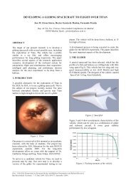
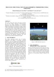
<strong>Inflatable</strong> <strong>Re</strong>-<strong>entry</strong> <strong>Demonstrator</strong> <strong>Technology</strong> (<strong>IRDT</strong>)<br />
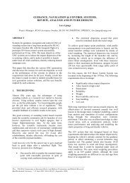
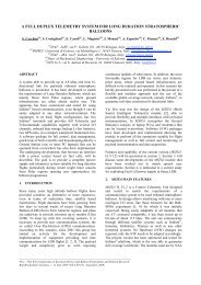
Artist’s impression of <strong>IRDT</strong> entering Earth’s atmosphere with<br />
flexible heat shield deployed (Image: <strong>ESA</strong>)<br />
<strong>IRDT</strong> is an <strong>ESA</strong> technology demonstrator project<br />
for a new concept, which enables re-<strong>entry</strong> from<br />
orbit and landing without the need of a heavy heat<br />
shield and parachute system. The 140 kg<br />
demonstrator vehicle system consists of a small<br />
ablative nose from which a cone-shaped flexible<br />
heat shield is inflated to provide braking and<br />
thermal protection during re-<strong>entry</strong>.<br />
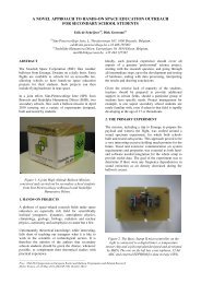
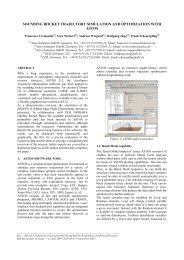
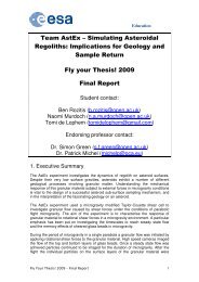
Cut out artist’s impression of <strong>IRDT</strong> with flexible heat shield and<br />
inflatable extension deployed (Image: <strong>ESA</strong>)<br />
When the flexible heat shield is deployed, it<br />
increases the capsule diameter from 80 cm to 2.3 m.<br />
This flexible shield consists of an internal network of<br />
rubber hoses pressurised with nitrogen, covered by<br />
an insulating layer (Multi-Layer Insulation) protected<br />
by a silica-based fabric impregnated with an ablative<br />
material. As its temperature increases, this ablative<br />
material decomposes, absorbing heat and thereby<br />
limiting the heat input to the capsule’s interior. The<br />
thickness of the material, i.e. number of layers, is<br />
designed to cope with the expected atmospheric<strong>entry</strong><br />
heat loadings with some margin.<br />
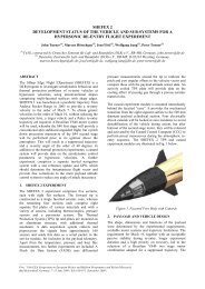
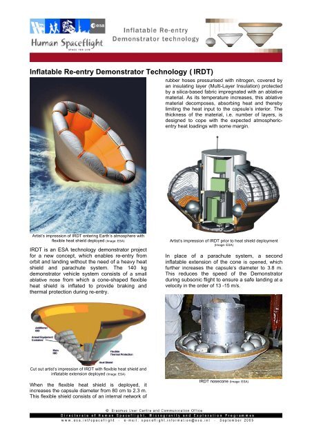
Artist’s impression of <strong>IRDT</strong> prior to heat shield deployment<br />
(Image: <strong>ESA</strong>)<br />
In place of a parachute system, a second<br />
inflatable extension of the cone is opened, which<br />
further increases the capsule’s diameter to 3.8 m.<br />
This reduces the speed of the <strong>Demonstrator</strong><br />
during subsonic flight to ensure a safe landing at a<br />
velocity in the order of 13 -15 m/s.<br />
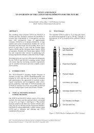
<strong>IRDT</strong> nosecone (Image: <strong>ESA</strong>)
Artist’s impression of <strong>IRDT</strong> scenario involving the Automated Transfer Vehicle (Image: <strong>ESA</strong>)<br />
The inflation process is triggered by the sequential<br />
firing of a series of pyro-valves, which progressively<br />
empties a set of 13 nitrogen bottles into the<br />
envelopes, at different stages of the mission. To<br />
ensure adequate stability during all phases of re<strong>entry</strong><br />
and provide proper deceleration, a spherecone<br />
shape, with a nose radius of 0.61 m and a cone<br />
half angle of 45º has been selected.<br />
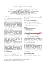
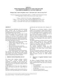
Soyuz Fregat upper stage <strong>entry</strong> configuration with <strong>IRDT</strong><br />
flexible heatshield deployed (Image: <strong>ESA</strong>)<br />
The inflatable heat shield has a number of<br />
advantages over existing designs. Not only can it<br />
be folded into a very small package, but it is<br />
lightweight and cost-effective. Once verified, this<br />
new technology can be used for re-<strong>entry</strong><br />
scenarios such as payload recovery from low<br />
Earth orbit, atmospheric research and as a means<br />
to return launcher upper stages for the planetary<br />
landers used for science missions.<br />
To facilitate post-landing recovery, a beacon similar<br />
to that on the Soyuz capsule was installed. A<br />
dedicated sensor package will monitor and record<br />
the flight parameters including two three-axis<br />
accelerometers, three gyroscopes, 23 temperature<br />
sensors in different internal locations and 81 CIMTs<br />
(Crystal Indicators of Maximum Temperature), within<br />
the ablative front shield at depths of 3, 6 and 9 mm.<br />
The crystals can be analysed post landing in order to<br />
determine the maximum temperature on re-<strong>entry</strong>.<br />
Such crystals can measure temperatures up to<br />
2000ºC.<br />
The <strong>IRDT</strong> is only dealing with atmospheric re-<strong>entry</strong><br />
and landing operations. For its launch into space and<br />
injection into a re-<strong>entry</strong> trajectory, it depends on a<br />
carrier vehicle such as a rocket.<br />
One spin-off of this technology that was partially<br />
funded through <strong>ESA</strong>’s <strong>Technology</strong> Transfer<br />
Programme was a way to escape burning<br />
buildings. This idea was shown at the Paris Air<br />
Show in 2005.
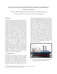
Mission Profile<br />
For the test flight of the <strong>Inflatable</strong> <strong>Re</strong>-<strong>entry</strong> and<br />
Descent <strong>Technology</strong> (<strong>IRDT</strong>) in Autumn 2005, the<br />
<strong>IRDT</strong> will be launched into a sub-orbital ballistic<br />
re-<strong>entry</strong> trajectory by a Volna rocket, which is fired<br />
from a Russian naval submarine positioned in the<br />
Barents Sea in the area of Severomorsk, Russia.<br />
Launch profile of <strong>IRDT</strong> and Volna launcher (Image: <strong>ESA</strong>)<br />
The launch is scheduled to take place at 23:30<br />
Central European Time. Following lift-off the<br />
Volna launch vehicle will go through different<br />
stages of separation. Once the first stage<br />
propulsion system has finished firing this stage<br />
will separate from rest of the launch vehicle and<br />
its payload. This will coincide with ignition of the<br />
second stage engines (2/3 in above image). Once<br />
these have finished firing, this stage will also<br />
separate. At the same time with third stage<br />
engines will be ignited (4/5 in above image).<br />
During the third stage firing, the payload<br />
compartment will be depressurised. Towards the<br />
end of the third stage sequence the spacecraft will<br />
be reoriented on its trajectory before the capsule<br />
cover is jettisoned (7 in above image). Separation<br />
of the <strong>IRDT</strong> from third stage follows (8 in above<br />
image). This occurs at five minutes and six<br />
seconds after launch at an altitude of 202.75 km.<br />
The <strong>IRDT</strong> is now free from the launch vehicle and<br />
continues on a ballistic trajectory. 2.6 seconds<br />
following final separation, the <strong>IRDT</strong> spins up<br />
around its axis of symmetry (9 in above image).<br />
Six seconds later at five minutes and 12 seconds<br />
after lift-off, the experiment compartment is<br />
‘armed’ and the platform covering the experiment<br />
container jettisoned (10 in above image).<br />
<strong>IRDT</strong> re-<strong>entry</strong> and landing profile (Image: <strong>ESA</strong>)
Ground track of the <strong>IRDT</strong> following separation from the launcher (Image: <strong>ESA</strong>)<br />
After this event, the <strong>IRDT</strong> reaches its maximum<br />
altitude of 258.2 km. At 11 minutes and 2<br />
seconds after launch, the <strong>IRDT</strong> is now on the<br />
downward part of the flight trajectory at an altitude<br />
of 238.5 km and travelling at 6.7 km/s. At this<br />
point the pyro-valves are fired, which empty the<br />
nitrogen bottles which inflate the flexible heat<br />
shield.<br />
Four minutes later at 15 minutes and six seconds<br />
after launch, the <strong>IRDT</strong> is entering the Earth’s<br />
atmosphere at an altitude of 100km and an angle<br />
of -6.84º. At this point the <strong>IRDT</strong> is travelling at a<br />
velocity of 6.9 km/s. Passing through the upper<br />
atmospheric layers imposes the highest dynamic<br />
pressure, heat flux and acceleration loads onto<br />
the system.<br />
After 20 minutes following launch the <strong>IRDT</strong> has<br />
greatly reduced its velocity to approximately 230<br />
km/h and is at an altitude of between 12-14 km.<br />
At this point the second cascade is inflated. This<br />
further reduces the speed to 15.1 m/s on landing.<br />
This is at approximately 30 minutes after launch.<br />
<strong>IRDT</strong> landing Site (Image: <strong>ESA</strong>)
Development<br />
In 1997 <strong>ESA</strong>, the European Commission and the<br />
German company DaimlerChrysler Aerospace<br />
(DASA, now part of EADS) decided to co-fund a<br />
joint effort with NPO Lavochkin, the Russian<br />
company that developed the original <strong>IRDT</strong><br />
technology.<br />
The Russian spacecraft Mars'96, which was<br />
launched in November 1996, carried two modules<br />
designed to land on that planet's surface. This<br />
mission was unfortunstely lost due to a launcher<br />
failure. For the last part of the mission, the use of<br />
an <strong>Inflatable</strong> <strong>Re</strong>-Entry and Descent <strong>Technology</strong><br />
(<strong>IRDT</strong>) had been forseen. The main components<br />
of this system were an aerobraking and thermally<br />
protective shell, a densely packed inflating<br />
material and a pressurisation system.<br />
The first flight opportunity thereafter was on 9<br />
February 2000. This was a low-cost opportunity<br />
as it was also the first test flight of the Soyuz-U<br />
launcher with a Fregat upper stage. The Soyuz-<br />
U/Fregat was undergoing its first of two flight tests<br />
as part of the contract to launch the Agency’s four<br />
Cluster satellites. However, a tear in the inflatable<br />
heat shield caused a higher than planned velocity<br />
impact.<br />
An international team developed the <strong>IRDT</strong> project<br />
under a European Space Agency contract with<br />
European industry with EADS Space<br />
Transportation in Bremen, Germany, as a prime<br />
contractor and NPO-Lavochkin as a major<br />
subcontractor. For the launch of the <strong>IRDT</strong><br />
<strong>Demonstrator</strong>-2R in October 2005, this<br />
programme was performed in cooperation with,<br />
among others, the Russian Federal Space<br />
Agency, the International Scientific and Technical<br />
Centre, the State Rocket Centre (Makeev Design<br />
Bureau), the Space <strong>Re</strong>search Institute (IKI) of the<br />
Russian Academy of Sciences, the Russian<br />
research institute TsNIIMash and the Russian<br />
Navy.<br />
NPO Lavochkin developed the <strong>IRDT</strong><br />
<strong>Demonstrator</strong> within the framework of the Moscow<br />
based International Science and <strong>Technology</strong><br />
Centre (ISTC) - an intergovernmental organisation<br />
dedicated to non-proliferation. DASA built the<br />
sensor package and the demonstrator’s payload.<br />
<strong>ESA</strong> contributed to the project both via ISTC and<br />
through a contract with DASA.<br />
The 2005 flight opportunity of the <strong>Demonstrator</strong>-<br />
2R is the third flight vehicle of the <strong>IRDT</strong> series as<br />
the first two attempts to launch an <strong>IRDT</strong><br />
spacecraft were unsuccessful. It was sent to<br />
Severomorsk to begin launch preparations on 24<br />
May 2005.<br />
The launch was originally planned for December<br />
2004 but postponed at the request of engineers<br />
working on the project, who wanted to carry out<br />
further tests to increase the spacecraft’s reliability.<br />
The pressure regulation system and the launcher<br />
interface have been improved, and the heat shield<br />
strengthened. Telemetry and navigation systems<br />
allowing better descent monitoring and more<br />
efficient recovery operations have also been<br />
introduced, and a camera will provide images of<br />
the various stages of deployment.<br />
Among several longer-term improvements to the<br />
capsule, it is foreseen to increase the payload/<br />
mass ratio and offer soft-landing capabilities. In<br />
addition to applications such as for low Earth orbit<br />
sample return, as a planetary <strong>entry</strong> and landing<br />
system and as launcher upper stage return, a<br />
number of other applications have been identified,<br />
and will be more thoroughly investigated.