752/135U Ultrasonic Motion Detector, 22554 - Clipsal
752/135U Ultrasonic Motion Detector, 22554 - Clipsal
752/135U Ultrasonic Motion Detector, 22554 - Clipsal

You also want an ePaper? Increase the reach of your titles
YUMPU automatically turns print PDFs into web optimized ePapers that Google loves.
<strong>Ultrasonic</strong><br />
<strong>Motion</strong> <strong>Detector</strong><br />
<strong>752</strong>/<strong>135U</strong><br />
Installation Instructions<br />
<strong>22554</strong> F1454-02 <strong>752</strong>-<strong>135U</strong> Instruction.indd 1 23/02/2011 3:20:15 PM
<strong>752</strong>/<strong>135U</strong> <strong>Ultrasonic</strong> <strong>Motion</strong> <strong>Detector</strong> Installation Instructions<br />
Table of Contents<br />
1.0 Introduction .....................................................................................................3<br />
2.0 How it Works ....................................................................................................3<br />
2.1 <strong>Ultrasonic</strong> Detection...................................................................................3<br />
3.0 Identification of Parts .....................................................................................4<br />
3.1 <strong>Detector</strong> .....................................................................................................4<br />
3.2 Power Supply .............................................................................................4<br />
4.0 Location ............................................................................................................5<br />
5.0 Detection Pattern .............................................................................................5<br />
6.0 Mounting Procedure ........................................................................................6<br />
7.0 Wiring Diagram ................................................................................................6<br />
8.0 Commissioning ................................................................................................7<br />
9.0 Logic Bypass Function ...................................................................................7<br />
10.0 Technical Specifications .................................................................................8<br />
11.0 Troubleshooting ...............................................................................................9<br />
12.0 Notes ......................................................................................................... 10-11<br />
13.0 Warranty ........................................................................................................12<br />
© <strong>Clipsal</strong> Australia Pty Ltd<br />
<strong>22554</strong> F1454-02 <strong>752</strong>-<strong>135U</strong> Instruction.indd 2 23/02/2011 3:20:15 PM
<strong>752</strong>/<strong>135U</strong> <strong>Ultrasonic</strong> <strong>Motion</strong> <strong>Detector</strong> Installation Instructions<br />
1.0 Introduction<br />
The <strong>Clipsal</strong> <strong>752</strong>/<strong>135U</strong> <strong>Motion</strong> Sensor uses ultrasonic technology to perform<br />
the ultimate task of sensing.<br />
2.0 How it Works<br />
2.1.<strong>Ultrasonic</strong> Detection<br />
The <strong>752</strong>/<strong>135U</strong> consists of 2 transmitters and 2 receiver transducers to provide total<br />
volumetric sensing with no blind spots.<br />
The sensor operates on 24V d.c. and is designed to work with the <strong>752</strong>PR power<br />
and relay switching module (supplied).<br />
When someone enters a room in which the sensor controls the lighting the lights<br />
turn on automatically, and in this manner the load can be controlled. The signal<br />
derived activates an adjustable timer (30 seconds to 30 minutes), which in turn<br />
activates an electrical relay in the power pack, turning the lights on.<br />
If no movement or presence is detected for the time selected, the relay<br />
de-energises, turning the lights and load off.<br />
The <strong>752</strong>PR device has a C-Bus auxiliary unit connection terminal which is to be<br />
connected only to a C-Bus L5504AUX or C-Bus bus coupler unit.<br />
© <strong>Clipsal</strong> Australia Pty Ltd<br />
3 of 12<br />
<strong>22554</strong> F1454-02 <strong>752</strong>-<strong>135U</strong> Instruction.indd 3 23/02/2011 3:20:15 PM
<strong>752</strong>/<strong>135U</strong> <strong>Ultrasonic</strong> <strong>Motion</strong> <strong>Detector</strong> Installation Instructions<br />
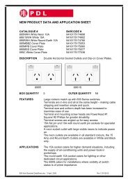
3.0 Identification of Parts<br />
3.1 <strong>Detector</strong><br />
3.2 Power Supply<br />
4 of 12<br />
Cut out to suit<br />
load cable<br />
Incoming Mains<br />
Supply Cable<br />
Load Output<br />
Terminals<br />
Cover<br />
PCB Fixing Screws<br />
<strong>752</strong>LD Lead<br />
Connector for <strong>752</strong>LD<br />
(lead to sensor)<br />
Output for connection<br />
to C-Bus bus coupler<br />
or auxiliary unit<br />
Base<br />
© <strong>Clipsal</strong> Australia Pty Ltd<br />
<strong>22554</strong> F1454-02 <strong>752</strong>-<strong>135U</strong> Instruction.indd 4 23/02/2011 3:20:17 PM
<strong>752</strong>/<strong>135U</strong> <strong>Ultrasonic</strong> <strong>Motion</strong> <strong>Detector</strong> Installation Instructions<br />
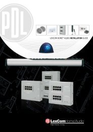
4.0 Location<br />
The best position to mount the sensor is on the ceiling in the centre of the room. It<br />
has a nominal coverage of 15m x 15m (225m 2 ) with 360° coverage.<br />
A B<br />
Plan of Room (example)<br />
Best position<br />
Note: Do not mount close to objects which can change temperatures rapidly e.g.<br />
air-conditioning vents, heater flues.<br />
5.0 Detection Pattern<br />
Detection and range pattern<br />
4.5m<br />
3m<br />
Mounted in hallway with 3m ceiling<br />
© <strong>Clipsal</strong> Australia Pty Ltd<br />
30m<br />
Mounted in stockroom 6m above floor<br />
Plan of Room (example)<br />
Incorrect positions<br />
<strong>752</strong>/<strong>135U</strong><br />
<strong>752</strong>/<strong>135U</strong><br />
6m 9m 9m<br />
6m<br />
Forklift detection Walking detection<br />
5 of 12<br />
<strong>22554</strong> F1454-02 <strong>752</strong>-<strong>135U</strong> Instruction.indd 5 23/02/2011 3:20:17 PM
<strong>752</strong>/<strong>135U</strong> <strong>Ultrasonic</strong> <strong>Motion</strong> <strong>Detector</strong> Installation Instructions<br />
6.0 Mounting Procedure<br />
1. Fit power supply in ceiling space within 1m of sensor position. (Fit surface mount<br />
socket or similar for supply from lighting circuit.)<br />
6 of 12<br />
a. Fix base of power supply to beam.<br />
b. Fix PCB to base using screws provided.<br />
c. Fit <strong>752</strong>LD (one metre lead) to connector on PCB at extra low voltage end.<br />
d. Fit load cables to terminals on PCB, stripped to length as shown.<br />
e. Cut out cover as required to suit load cables.<br />
f. Screw cover to base.<br />
2. Fit sensor to ceiling in (a predetermined) position.<br />
a. Fix mounting flange to ceiling.<br />
b. Cut hole for <strong>752</strong>LD lead cable (Ø20mm hole).<br />
c. Fit <strong>752</strong>LD lead to sensor.<br />
d. Fix sensor to mounting flange and secure using side fixing screws.<br />
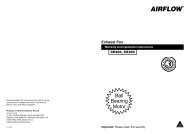
7.0 Wiring Diagram<br />
Hard wired<br />
incoming<br />
mains<br />
Warning<br />
AEN<br />
LIGHTING LOAD<br />
SW A E N<br />
<strong>752</strong>PR Module<br />
Mains Side Extra Low<br />
Voltage Side<br />
Switched<br />
Control<br />
Active A<br />
B<br />
<strong>752</strong>LD LEAD<br />
6 Way Cable (1m)<br />
<strong>752</strong>/<strong>135U</strong><br />
Sensor Head<br />
20mm 9mm<br />
Output for<br />
connection to<br />
C-Bus auxiliary<br />
unit L5504AUX<br />
or bus coupler<br />
It is recommended that this product should be hard wired as per the wiring diagram.<br />
When connecting multiple <strong>752</strong>PR modules to control the same load, 3 pin plugs or<br />
similar must not be used, as this can result in the plugtop pins becoming ‘live’ under<br />
certain conditions.<br />
For safety reasons, it is recommended to always shut down power to all relevant<br />
circuits before undertaking any installation or maintenance of this product.<br />
© <strong>Clipsal</strong> Australia Pty Ltd<br />
<strong>22554</strong> F1454-02 <strong>752</strong>-<strong>135U</strong> Instruction.indd 6 23/02/2011 3:20:17 PM
<strong>752</strong>/<strong>135U</strong> <strong>Ultrasonic</strong> <strong>Motion</strong> <strong>Detector</strong> Installation Instructions<br />
8.0 Commissioning<br />
Once power has been installed, determine which sensitivity setting and time delay<br />
best suits the application.<br />
Time Delay Tables<br />
Example of timer settings in minutes<br />
Stock Room =# 15<br />
Hallways =# 10<br />
Restroom =#7<br />
Office =#8<br />
Classroom =#9<br />
9.0 Logic Bypass Function<br />
Note: When logic key or paper clip is inserted into the slot, lights will always be<br />
on. There is no shock hazard present when using a logic key or a paper clip. This<br />
bypass function is for emergency use only.<br />
© <strong>Clipsal</strong> Australia Pty Ltd<br />
Approximate Sensitivity Adjustment<br />
3m on each side =#2<br />
6m on each side =#3<br />
9m on each side =#5<br />
12m on each side =#7<br />
15m on each side =#8<br />
Note: When making adjustments do not attempt to force adjustment<br />
screw past limits.<br />
SENSITIVITY BY PASS MINUTES<br />
7 of 12<br />
<strong>22554</strong> F1454-02 <strong>752</strong>-<strong>135U</strong> Instruction.indd 7 23/02/2011 3:20:17 PM
<strong>752</strong>/<strong>135U</strong> <strong>Ultrasonic</strong> <strong>Motion</strong> <strong>Detector</strong> Installation Instructions<br />
10.0 Technical Specifications<br />
Model <strong>752</strong>/<strong>135U</strong> <strong>Ultrasonic</strong> <strong>Motion</strong> <strong>Detector</strong>.<br />
Time Delay Adjustment Variable from approximately 30 seconds<br />
to 30 minutes.<br />
Coverage 360° (walking) = 4.5m x 30m (Note: mounted in<br />
room with 3m ceiling height).<br />
Room Size Adjustment Sensitivity adjustment for ultrasonic detection.<br />
Bypass Override Function Logic key or paper clip. Only for emergency use.<br />
Walk Test Indicator Red LED = <strong>Ultrasonic</strong>.<br />
Ambient Ranges Operating Temperature = (0°C to 50°C)<br />
Humidity - 0-95% RH non-condensing.<br />
Colour White<br />
Enclosure High-impact U.L. approved material with base to<br />
comply with all flammability rating standards.<br />
Description 72mm x 127mm x 35mm. Weight 160g.<br />
<strong>752</strong> Power Supply and Switched Module (<strong>752</strong>PR)<br />
Operating Voltage Range 192V a.c. min.- 265V a.c. max.<br />
Rated Nominal Voltage 240V a.c.<br />
Operating Frequency 50Hz<br />
Output Power 7VA max. @ 240V<br />
Unfiltered d.c. Voltage Output @ 240V<br />
a.c. Input (no load)<br />
24V max.<br />
Continuous d.c. Load Current Allowed 100mA max.<br />
Switched Active Contact Rating (N.O.) 240V a.c. 10AX max. suitable for fluorescent,<br />
inductive and incandescent loads.<br />
C-Bus Output Connection Compatible with C-Bus bus coupler or<br />
auxiliary unit.<br />
Operating Temperature Range 0°C min. - 50°C max.<br />
Number of <strong>752</strong> Series <strong>Motion</strong><br />
<strong>Detector</strong>s allowed to connect<br />
8 of 12<br />
One<br />
© <strong>Clipsal</strong> Australia Pty Ltd<br />
<strong>22554</strong> F1454-02 <strong>752</strong>-<strong>135U</strong> Instruction.indd 8 23/02/2011 3:20:17 PM
<strong>752</strong>/<strong>135U</strong> <strong>Ultrasonic</strong> <strong>Motion</strong> <strong>Detector</strong> Installation Instructions<br />
11.0 Troubleshooting<br />
Problem The power is restored and the red and LED does not blink<br />
when making motion.<br />
Solution A Adjust sensitivity and set level to a higher setting as required by<br />
observing red LED.<br />
Solution B Remove sensor and measure if 24V d.c. is present between<br />
red and black leads. If no voltage is present, check power<br />
connection and power/switch pack. If voltage is present, replace<br />
sensor with new one and send defective sensor to <strong>Clipsal</strong><br />
Australia Pty Ltd.<br />
Problem Lights are on continuously and do not shut off when no<br />
one is present.<br />
Solution Re-check all your connections then disconnect sensor while<br />
power is still on. If lights remain on, this indicates that there<br />
is a short in the <strong>752</strong>LD Lead connecting the sensor and the<br />
power/switch module. Solution to this problem is to replace the<br />
<strong>752</strong>LD Lead. Check also for external causes such as excessive<br />
turbulence (hanging mobiles, etc).<br />
Problem Lights will not switch on even after sensor is disconnected<br />
and red and blue wires are shorted.<br />
Solution This could indicate a broken wire in the <strong>752</strong>LD Lead. Next,<br />
disconnect the <strong>752</strong>LD Lead at the power/switch module and<br />
short the pins where the red and blue wires connect. If lights<br />
still do not switch on, replace power/switch module after<br />
checking if all connections were made correctly.<br />
Problem LED blinks but lights will not switch on.<br />
Solution Check if sensor is working when bypassing all electronics. This<br />
can be done by inserting the key provided with each unit. If<br />
lights switch on, replace defective sensor.<br />
Problem After all connections are verified, lights stay on when no<br />
one is present, and from time to time LED blinks.<br />
Solution Turn sensitivity adjustment to a lower setting and/or physically<br />
rotate sensor by 90°<br />
© <strong>Clipsal</strong> Australia Pty Ltd<br />
9 of 12<br />
<strong>22554</strong> F1454-02 <strong>752</strong>-<strong>135U</strong> Instruction.indd 9 23/02/2011 3:20:17 PM
<strong>752</strong>/<strong>135U</strong> <strong>Ultrasonic</strong> <strong>Motion</strong> <strong>Detector</strong> Installation Instructions<br />
12.0 Notes<br />
10 of 12<br />
© <strong>Clipsal</strong> Australia Pty Ltd<br />
<strong>22554</strong> F1454-02 <strong>752</strong>-<strong>135U</strong> Instruction.indd 10 23/02/2011 3:20:17 PM
<strong>752</strong>/<strong>135U</strong> <strong>Ultrasonic</strong> <strong>Motion</strong> <strong>Detector</strong> Installation Instructions<br />
12.0 Notes<br />
© <strong>Clipsal</strong> Australia Pty Ltd<br />
11 of 12<br />
<strong>22554</strong> F1454-02 <strong>752</strong>-<strong>135U</strong> Instruction.indd 11 23/02/2011 3:20:17 PM
13.0 Warranty<br />
1) The benefits conferred herein are in addition to, and in no way shall be deemed to derogate;<br />
either expressly or by implication, any or all other rights and remedies in respect to <strong>Clipsal</strong><br />
Product, which the consumer has under the Commonwealth Trade Practices Act or any other<br />
similar State or Territory Laws.<br />
2) The warrantor is <strong>Clipsal</strong> Australia Pty Ltd of 33-37 Port Wakefield Road, Gepps Cross, SA<br />
5094. With registered offices in all Australian States.<br />
3) This <strong>Clipsal</strong> Product is guaranteed against faulty workmanship and materials for a period of<br />
two (2) years from the date of installation.<br />
4) <strong>Clipsal</strong> Australia Pty Ltd reserves the right, at its discretion, to either repair free of parts<br />
and labour charges, replace or offer refund in respect to any article found to be faulty due to<br />
materials, parts or workmanship.<br />
5) This warranty is expressly subject to the <strong>Clipsal</strong> Product being installed, wired, tested,<br />
operated and used in accordance with the manufacturer’s instructions.<br />
6) All costs of a claim shall be met by <strong>Clipsal</strong> Australia Pty Ltd, however should the product<br />
that is the subject of the claim be found to be in good working order, all such costs shall be<br />
met by the claimant.<br />
7) When making a claim, the consumer shall forward the <strong>Clipsal</strong> Product to the nearest office<br />
of <strong>Clipsal</strong> Australia Pty Ltd with adequate particulars of the defect within 28 days of the fault<br />
occurring. The product should be returned securely packed, complete with details of the date<br />
and place of purchase, description of load, and circumstances of malfunction.<br />
For all warranty enquiries, contact your local <strong>Clipsal</strong> sales representative. The address and contact<br />
number of your nearest <strong>Clipsal</strong> Australia office can be found at http://www.clipsal.com/locations<br />
<strong>Clipsal</strong> Australia Pty Ltd<br />
A member of Schneider Electric<br />
Contact us: clipsal.com/feedback<br />
National Customer Care Enquiries:<br />
Tel 1300 2025 25<br />
Fax 1300 2025 56<br />
F1454/02 10339251<br />
clipsal.com<br />
<strong>Clipsal</strong> Australia Pty Ltd reserves the right to change<br />
specifications, modify designs and discontinue items without<br />
incurring obligation and whilst every effort is made to ensure that<br />
descriptions, specifications and other information in this catalogue<br />
are correct, no warranty is given in respect thereof and the<br />
company shall not be liable for any error therein.<br />
© <strong>Clipsal</strong> Australia Pty Ltd. The identified trademarks and<br />
copyrights are the property of <strong>Clipsal</strong> Australia Pty Ltd unless<br />
otherwise noted.<br />
CLIPCOM <strong>22554</strong> February 2011<br />
<strong>22554</strong> F1454-02 <strong>752</strong>-<strong>135U</strong> Instruction.indd 12 23/02/2011 3:20:17 PM