Instructions for use of Siemens D5000STD.pdf
Instructions for use of Siemens D5000STD.pdf
Instructions for use of Siemens D5000STD.pdf

You also want an ePaper? Increase the reach of your titles
YUMPU automatically turns print PDFs into web optimized ePapers that Google loves.
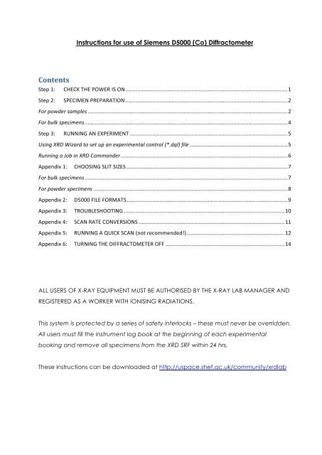
Contents<br />
<strong>Instructions</strong> <strong>for</strong> <strong>use</strong> <strong>of</strong> <strong>Siemens</strong> D5000 (Co) Diffractometer<br />
Step 1: CHECK THE POWER IS ON............................................................................................................1<br />
Step 2: SPECIMEN PREPARATION............................................................................................................2<br />
For powder samples .....................................................................................................................................2<br />
For bulk specimens.......................................................................................................................................4<br />
Step 3: RUNNING AN EXPERIMENT .........................................................................................................5<br />
Using XRD Wizard to set up an experimental control (*.dql) file .................................................................5<br />
Running a Job in XRD Commander...............................................................................................................6<br />
Appendix 1: CHOOSING SLIT SIZES ...........................................................................................................7<br />
For bulk specimens.......................................................................................................................................7<br />
For powder specimens .................................................................................................................................8<br />
Appendix 2: D5000 FILE FORMATS...........................................................................................................9<br />
Appendix 3: TROUBLESHOOTING ...........................................................................................................10<br />
Appendix 4: SCAN RATE CONVERSIONS .................................................................................................11<br />
Appendix 5: RUNNING A QUICK SCAN (not recommended!).................................................................12<br />
Appendix 6: TURNING THE DIFFRACTOMETER OFF ...............................................................................14<br />
ALL USERS OF X-RAY EQUIPMENT MUST BE AUTHORISED BY THE X-RAY LAB MANAGER AND<br />
REGISTERED AS A WORKER WITH IONISING RADIATIONS.<br />
This system is protected by a series <strong>of</strong> safety interlocks – these must never be overridden.<br />
All <strong>use</strong>rs must fill the instrument log book at the beginning <strong>of</strong> each experimental<br />
booking and remove all specimens from the XRD SRF within 24 hrs.<br />
These instructions can be downloaded at http://uspace.shef.ac.uk/community/xrdlab
Step 1: CHECK THE POWER IS ON<br />
Check the current status <strong>of</strong> the generator. The machine is already on if:<br />
-‐‑ the X-rays On light is lit<br />
-‐‑ The digital display on the front <strong>of</strong> the machine does NOT read 0 kV, 0mA.<br />
If the machine is already ON, proceed to Step 2.<br />
If the machine is NOT ON, then:<br />
-‐‑ Make sure that the PC is on, and that the ‘XRD Commander’ s<strong>of</strong>tware is NOT<br />
running. If it is running, close it.<br />
-‐‑ Flick the green ‘Mains’ switch to on, if not already.<br />
-‐‑ Turn the Key to the I position, if not already.<br />
-‐‑ Switch generator to standby mode by pressing the WHITE button and holding it<br />
in <strong>for</strong> 5 seconds. A buzzing alarm will sound if water flow is insufficient.<br />
-‐‑ Pull out the keypad. Press ‘Shift’ ‘6’ ‘1’ and then ‘Enter’<br />
-‐‑ Press the GREEN button to start the generator.<br />
-‐‑ You may hear the machine trip – this is normal <strong>for</strong> this type <strong>of</strong> generator. Press<br />
the WHITE and GREEN buttons again.<br />
-‐‑ The generator should now be at the minimum settings <strong>of</strong> 20kV and 5mA.<br />
-‐‑ Using the black square buttons on the front left panel <strong>of</strong> the D5000, hold the<br />
MODE button and press the ↑ arrow once. Turn the kV up to 40 by holding the<br />
EDIT button and repeatedly pressing the ↑ arrow.<br />
-‐‑ Hold the MODE button and press the ↑ arrow once. Turn the mA up to 30 by<br />
holding the EDIT button and repeatedly pressing the ↑ arrow. Hold MODE and<br />
press the ↓ arrow twice to return to the main display.<br />
-‐‑ On the PC, check to see if the ‘XRD Commander’ s<strong>of</strong>tware is running already;<br />
NEVER HAVE MULTIPLE COPIES OF XRD COMMANDER RUNNING!<br />
if it is not already running, start it by double-left clicking on its icon on the<br />
desktop.<br />
-‐‑ Proceed to Step 2.<br />
1 | P age
Step 2: SPECIMEN PREPARATION<br />
Please note that old samples must be removed, tipped in to aluminium foil, labelled<br />
with the date and name <strong>of</strong> whoever ran the sample, then placed in to the <strong>use</strong>d<br />
specimen box <strong>for</strong> collection. When prepared, proceed to Step 3.<br />
For powder samples<br />
Make sure your powder is well-ground. To prepare a specimen, you will require:<br />
Spatula<br />
Remove the back plate from the specimen holder, and pop the holder ‘ring’ on top <strong>of</strong><br />
the metal plate:<br />
Fill the specimen holder with an appropriate amount <strong>of</strong> your sample. Use the<br />
microscope slide to ensure that the powder is flat, and level with the top <strong>of</strong> the<br />
specimen holder.<br />
Specimen holder<br />
with back plate<br />
Microscope Slide<br />
Metal plate<br />
2 | P age
Remove any excess:<br />
Clip the back plate on to the specimen holder:<br />
Carefully lift the whole arrangement (the specimen holder and metal plate) and turn it<br />
over:<br />
3 | P age
Very carefully remove the metal plate. Try to lift it <strong>of</strong>f directly – any sliding motion could<br />
ca<strong>use</strong> a smearing effect on the powder surface, which is exactly what we’re trying to<br />
prevent!<br />
Label the specimen holder with marker pen.<br />
For bulk specimens<br />
1. Make sure your specimen has at least one surface which is level and smooth.<br />
2. Remove or add Apiezon putty to the plastic specimen holder as necessary, and<br />
mould the putty so that your specimen can sit on top <strong>of</strong> a mound <strong>of</strong> putty.<br />
3. Place the specimen on to the putty and press down lightly to help it stick.<br />
4. Turn the holder upside down and gently press down on to a flat surface. The top<br />
<strong>of</strong> the specimen MUST BE LEVEL with the top <strong>of</strong> this specimen holder.<br />
5. Load the plastic specimen holder with specimen into the large round spring-<br />
loaded D5000 specimen holder, and load in to instrument.<br />
Key point #1: if the specimen height is incorrect, you WILL get specimen height<br />
displacement errors in your data, e.g. if the specimen is too high, your Bragg reflections<br />
will be shifted to higher angles (and too low, peaks shifted to lower angles). This can<br />
make phase analysis very difficult!<br />
Key point #2: the Apiezon putty is partly crystalline, so will give peaks in your diffraction<br />
pattern should it get in to the beam. Make sure your specimen is mounted on the<br />
putty, and not embedded too deeply into it!<br />
4 | P age
Step 3: RUNNING AN EXPERIMENT<br />
NOTE: NEVER HAVE MULTIPLES OF XRD COMMANDER RUNNING!<br />
If you wish to <strong>use</strong> a previously created *.dql file, skip the section on using XRD Wizard;<br />
otherwise…<br />
Using XRD Wizard to set up an experimental control (*.dql) file<br />
From the Desktop, start ‘XRD Wizard’<br />
-‐‑ Click on to the ‘Quick Edit’ tab.<br />
-‐‑ Check the Scantype (<strong>for</strong> regular ϑ:2ϑ work, choose ‘Locked Coupled’)<br />
-‐‑ Check Scan Mode (Continuous or Step Scan)<br />
o There is not much difference between the two modes. ‘Continuous’ is<br />
kinder to the machine’s gearing. Step scan is better <strong>for</strong> high quality work,<br />
i.e. data <strong>for</strong> Rietveld analysis, lattice parameter calculation, stress analysis.<br />
-‐‑ Enter the desired ‘Scan Definition’:<br />
o Enter start angle, in º2ϑ. For phase analysis work, a ‘Start’ angle <strong>of</strong> ~ 5-20<br />
º2 , is usually adequate, depending on sample.<br />
o Enter stop angle, in º2ϑ. Stopping at 60-80 º2ϑ, is usually adequate <strong>for</strong><br />
phase analysis work. For Rietveld work, you should aim <strong>for</strong> a higher stop<br />
angle. The maximum permitted angle is 150 º2ϑ.<br />
o Enter step size (0.02 is a good standard, though 0.05 is <strong>of</strong>ten a better choice<br />
<strong>for</strong> quick, good quality data <strong>for</strong> phase analysis work. Use the minimum<br />
possible value, 0.01, <strong>for</strong> unit cell refinement or residual stress analysis only).<br />
o Enter the desired scan rate – this has to be in seconds/step (see Appendix 4<br />
<strong>for</strong> help on converting between degrees/minute and seconds/step if<br />
necessary). Make sure you will have enough time to complete your<br />
experiment in your allotted time.<br />
-‐‑ Set appropriate values <strong>for</strong> the ‘Motorized Slits’:<br />
o The D5000 has variable Divergence and Antiscatter Slits – the wider these<br />
are set, the wider the area illuminated by X-rays. See Appendix 1 <strong>for</strong> slit<br />
sizes appropriate to your specimen / specimen holder size.<br />
5 | P age
-‐‑ Set ‘Sample Rotation’ On or Off as desired. DO NOT USE ROTATION IF<br />
SCANNING BELOW 20 º2ϑ.<br />
o If set to On, enter the rotation speed (0 – 15 rpm).<br />
-‐‑ Click ‘File’, then ‘Save As’ to save your *.dql file.<br />
If you wish to run a multi-segment scan, click ‘Add’ in the ‘Ranges’ area, and repeat<br />
the steps above as appropriate be<strong>for</strong>e clicking ‘File’, then ‘Save As’.<br />
NOTE: *.dql files have nothing to do with your specimen! They merely tell the machine<br />
how to per<strong>for</strong>m the experiment. You can re-<strong>use</strong> the same *.dql files over and over<br />
again to make sure you collect data from your specimens in exactly the same way.<br />
Running a Job in XRD Commander<br />
In ‘XRD Commander’:<br />
-‐‑ Complete Step 1 to ensure the diffractometer is on.<br />
-‐‑ On the PC, check to see if the ‘XRD Commander’ s<strong>of</strong>tware is running already;<br />
NEVER HAVE MULTIPLE COPIES OF XRD COMMANDER RUNNING! If it is not<br />
already running, start it by double-left clicking on its desktop icon.<br />
-‐‑ Click on the ‘Jobs’ tab in the bottom left hand corner.<br />
-‐‑ Click ‘Create Jobs’ (button with four small blobs on, or from ‘Jobs’ menu)<br />
-‐‑ Leave ‘Pos’ blank<br />
-‐‑ Enter a Sample ID, i.e. a comment about the specimen <strong>for</strong> your own reference.<br />
-‐‑ In the Parameters column, click the square ‘...’ button, and navigate to your<br />
experiment’s *.dql file (i.e. the file created in ‘XRD Wizard’).<br />
-‐‑ In the ‘Raw Data’ column, click the square ‘...’ button and navigate to where<br />
you wish to save your data. Type in your desired File Name, and click ‘Open’.<br />
-‐‑ Leave the other columns blank.<br />
-‐‑ Click ‘Create’ to add your Job to the list.<br />
To begin the scan, highlight your Job in the list, and click the lightning bolt ‘Start<br />
Selected’ on the ‘Jobs’ tab. You may get a message stating that the drives need to be<br />
initialised – simply press OK to confirm. The diffraction pattern will then be displayed as<br />
it is collected on the ‘Adjust’ tab. Collect all specimens within 24 hrs.<br />
6 | P age
Appendix 1: CHOOSING SLIT SIZES<br />
The D5000 has variable Divergence and Antiscatter Slits – setting these wider increases<br />
the area illuminated by X-rays, meaning that more <strong>of</strong> your specimen can diffract and<br />
that the intensities in your diffracted pattern will be increased. However, this comes at<br />
the risk <strong>of</strong> exposing the specimen holder.<br />
For bulk specimens<br />
The area illuminated by X-rays is always around 14-15 mm deep (i.e. front to back as<br />
you look at the machine), but the width (i.e. distance side to side) covered varies<br />
dramatically with both 2ϑ and slit size, as shown in this graph:<br />
X-ray<br />
beam<br />
width<br />
/ mm<br />
30<br />
25<br />
20<br />
15<br />
10<br />
One wants to avoid getting peaks from the specimen holder. You should also avoid<br />
overspill at lower angles – this will lead to lower than expected intensities, which may<br />
make analyses difficult.<br />
5<br />
0<br />
0 20 40 60 80 100<br />
Scattering angle / °2θ<br />
To choose a slit size <strong>for</strong> a bulk specimen, first measure the specimen. On the graph<br />
above, imagine a horizontal line at this measured width. You want to select a<br />
divergence slit size that keeps the beam width below your line at all measured<br />
scattering angles. Bigger specimens are better!<br />
3°<br />
2°<br />
1°<br />
0.5°<br />
7 | P age
For powder specimens<br />
We have four standard Aluminium holders in the XRD SRF suitable <strong>for</strong> the D5000.<br />
Assuming the specimen is placed centrally, you should not observe any peaks from the<br />
aluminium holder when using the following slit sizes:<br />
Specimen Holder<br />
Used<br />
3 cm<br />
2 cm<br />
2 cm<br />
1.5 cm<br />
Maximum slit size permissible<br />
Rotating specimen Non-rotating specimen<br />
Up to 2.5° Up to 2.5°<br />
Up to 1.7° Up to 1.7°<br />
Up to 2° Up to 2°<br />
Up to 1.25° Up to 2°<br />
8 | P age
Appendix 2: D5000 FILE FORMATS<br />
In order to load your experimental data in to the SIeve+ s<strong>of</strong>tware <strong>for</strong> phase analysis:<br />
1. Open the program ConvX<br />
2. Choose File Type: DiffracPlus Raw<br />
3. Select File(s) to convert (can multi-‐select files where identical scan parameters <strong>use</strong>d)<br />
4. Set Output file details to ‘Files <strong>of</strong> Type’ = ASCII 2theta,I<br />
5. Check Output Parameters boxes filled in appropriately<br />
6. Press ‘Do That Convert Thang!!’ button and check <strong>for</strong> any files skipped.<br />
9 | P age
Appendix 3: TROUBLESHOOTING<br />
* If an alarm is sounding and the detector drive lost its reference position, or has hit a<br />
limit switch (i.e. if the detector appears to be at a very high or low (sub-zero) angle):<br />
o On the machine keypad, press ‘Shift’, ‘Circle’, ‘1’, ‘:’, ‘3’ and then ‘Enter’. If the<br />
machine beeps on keystrokes, try turning <strong>of</strong>f (Appendix 6) and back on first<br />
(Step 1).<br />
o Press and hold the central TUNING key; then press several times and hold either<br />
the ‘’ key or the ‘’ key to move the drive clockwise or anticlockwise.<br />
o Once the reference point is passed, per<strong>for</strong>m the initialisation procedure<br />
discussed in Appendix 5.<br />
* If the machine attempted to Start a new Job, has moved to the start angle, but now<br />
appears to be frozen:<br />
o Check that the enclosure door is properly closed. If it is:<br />
o Check the adjust tab: has an intensity scale (i.e. numbers) appeared on the left<br />
hand side <strong>of</strong> where the plot should appear. Are the figures in the Drive Controls<br />
pane changing at all? If no, then:<br />
o Close XRD Commander. Ignore any error messages.<br />
o Switch <strong>of</strong>f the diffractometer (Appendix 6, skipping any instructions that relate<br />
to XRD Commander)<br />
o Switch the diffractometer back on (Step 1).<br />
o Try your job again!<br />
* When starting a new run, the machine returns the Error message “Unable to send the<br />
kV to the Generator!” with Errorcode 400:<br />
o Switch the diffractometer back on (Step 1), starting at the part where instructed<br />
to press the white button.<br />
o Start your scan again.<br />
* The machine has been switched <strong>of</strong>f, and XRD Commander is hanging, or hangs when<br />
I try to reboot it.<br />
o Fill in the Machine Notes, and see the XRD SRF Manager, who will have to<br />
reconfigure the diffractometer settings.<br />
10 | P age
Appendix 4: SCAN RATE CONVERSIONS<br />
One <strong>of</strong> the ‘en<strong>for</strong>ced’ changes brought about by our <strong>use</strong> <strong>of</strong> the XRD Commander<br />
s<strong>of</strong>tware on the new <strong>Siemens</strong> D5000 is that we <strong>of</strong>ten we have to enter our scan rate in<br />
‘seconds/step’, rather than the more intuitive ‘degrees/minute’.<br />
It’s very easy to convert between the two, however, using the equation:<br />
t = 60s/r<br />
where: t = scan rate, in seconds/step<br />
So, <strong>for</strong> example:<br />
s = step size, in degrees<br />
r = scan rate, in degrees/minute<br />
STEP SIZE /<br />
Degrees 2ϑ<br />
SCAN RATE<br />
Degrees/min Seconds/Step<br />
0.01 0.1 6<br />
0.5 1.2<br />
1 0.6<br />
2 0.3<br />
0.02 0.1 12<br />
0.5 2.4<br />
1 1.2<br />
2 0.6<br />
0.05 0.1 30<br />
0.5 6<br />
1 3<br />
2 1.5<br />
11 | P age
Appendix 5: RUNNING A QUICK SCAN (not recommended!)<br />
NOTE: Though the easiest way to run an experiment on the D5000, YOUR DATA WILL NOT<br />
BE AUTOMATICALLY SAVED AT THE END OF A QUICK SCAN. Quick scans can be <strong>use</strong>ful,<br />
however, e.g. if you just to see if a particular peak is present or not.<br />
Upon opening ‘XRD Commander’, the <strong>use</strong>r is presented with the following interface:<br />
Menu Bar and<br />
Shortcut<br />
Buttons<br />
Drive Controls<br />
Sample rotation<br />
Shutter &<br />
X-ray tube<br />
controls<br />
‘Tabs’<br />
Diffracted Pattern<br />
‘Quick Scan’ settings<br />
Be<strong>for</strong>e we run a quick scan, we must first initialise the D5000. To do this:<br />
-‐‑ In the ‘Drive Controls’ area, tick the ‘Requested ‘ box to select all drives.<br />
-‐‑ In the ‘Menu Bar’, click ‘Diffractometer’, ‘Init Drives’. Untick the ‘Requested ‘.<br />
The D5000 has variable Divergence and Antiscatter Slits – setting these wider increases<br />
the area illuminated by X-rays, at the risk <strong>of</strong> exposing the specimen holder:<br />
-‐‑ Tick the two boxes <strong>for</strong> these slits, as shown above. Enter Slit Size values<br />
appropriate <strong>for</strong> your specimen (see Step 7 <strong>for</strong> suggestions) by typing the<br />
desired sizes in the boxes; both slits should be set to the same value.<br />
12 | P age
-‐‑ In the top ‘Menu Bar’, click ‘Diffractometer’ and select ‘Move Drives’. Untick<br />
the ‘ ‘ boxes <strong>for</strong> the Div. and Antis. Slits.<br />
Next, in the left hand panel <strong>of</strong> the ‘Adjust’ tab, choose the desired Rotation speed (if<br />
any) and click ‘Set’. Do NOT rotate if scanning below 20 º2ϑ.<br />
Next, the settings <strong>for</strong> a quick scan must be entered in the bottom panel <strong>of</strong> the ‘Adjust’<br />
window in ‘XRD Commander’. This is largely self-explanatory:<br />
Start angle, in º2θ Step size, in º2θ End angle, in º2θ<br />
Scan speed, in<br />
Deg/Min or Sec/Step<br />
-‐‑ Scantype should be ‘Locked Coupled‘ <strong>for</strong> phase analysis work. We can also<br />
alternate between a Continuous (recommended <strong>for</strong> phase analysis work; much<br />
kinder to the gearing) or Step Scan (very slightly more accurate) at the bottom.<br />
-‐‑ For phase analysis work, a ‘Start’ angle <strong>of</strong> ~ 5-20 º2ϑ is usually adequate,<br />
-‐‑ ‘Increment’: 0.02 is a good standard step size, though 0.05 is <strong>of</strong>ten best <strong>for</strong><br />
phase analysis work. 0.01 <strong>for</strong> unit cell refinement or residual stress analysis.<br />
-‐‑ Stopping at 60-80 º2ϑ, is adequate. The maximum angle permitted is 150 º2ϑ.<br />
-‐‑ ‘Scanspeed’ should be between 0.1 (will take many hours) and 2 (much faster)<br />
Deg/Min. For phase analysis work, faster scans should be OK, especially when<br />
combined with a step size <strong>of</strong> 0.05.<br />
Press ‘Start’ when ready<br />
REMEMBER: Save the data at the end <strong>of</strong> the scan:<br />
Scan speed unit<br />
selection<br />
- click ‘File’ and ‘Save As’. Choose the Bruker AT ver2.0 <strong>for</strong>mat.<br />
Start, stop, or<br />
continue a scan<br />
13 | P age
Appendix 6: TURNING THE DIFFRACTOMETER OFF<br />
The diffractometer is in <strong>use</strong> 24/7, and accordingly should always be left running with the<br />
‘XRD Commander’ program running and ready <strong>for</strong> the next <strong>use</strong>r. The D5000 has<br />
automated power control systems which will turn the generator down to lower settings<br />
to save power and preserve the X-ray tube.<br />
However, if the machine does need to be switched <strong>of</strong>f <strong>for</strong> any reason:<br />
-‐‑ In ‘XRD Commander’, stop any scans which may be running (either by clicking<br />
‘Stop’ on the Adjust tab or if this is greyed out by clicking to the Jobs tab,<br />
selecting the Active job and pressing the stop button).<br />
-‐‑ Using the black square buttons on the front left panel <strong>of</strong> the D5000, hold the<br />
MODE button and press the ↑ arrow twice. Turn the mA down to 5 by holding<br />
the EDIT button and repeatedly pressing the ↓ arrow.<br />
-‐‑ Hold the MODE button and press the ↓ arrow once. Turn the kV down to 20 by<br />
holding the EDIT button and repeatedly pressing the ↓ arrow. Hold MODE and<br />
press the ↓ arrow to return to the main display; the generator should now be at<br />
the minimum settings <strong>of</strong> 20kV and 5mA.<br />
-‐‑ On the front <strong>of</strong> the diffractometer, press the square yellow button.<br />
-‐‑ On the front <strong>of</strong> the diffractometer, turn the key to the ‘O’ position.<br />
-‐‑ On the front <strong>of</strong> the diffractometer, toggle the green Netz/Mains switch to the ‘O’<br />
position.<br />
If necessary, also switch <strong>of</strong>f the power completely at the isolator switch to the right<br />
behind the machine. After allowing 5 minutes <strong>for</strong> the X-ray tube to cool, you can also<br />
turn <strong>of</strong>f the water supply (unless there is suspected to be a serious problem with the<br />
water cooling system, i.e. a significant leak).<br />
Last edited: N.Reeves-McLaren 07/03/2013<br />
14 | P age