WOC 6e Guide to Microscopy
WOC 6e Guide to Microscopy
WOC 6e Guide to Microscopy

Create successful ePaper yourself
Turn your PDF publications into a flip-book with our unique Google optimized e-Paper software.
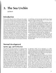
(a) Transmission electron micrograph<br />
Figure A-26 Comparison of Transmission<br />
and Scanning Electron Micrographs. (a)<br />
The transmission electron micrograph<br />
shows membranes of rough endoplasmic<br />
reticulum in the cy<strong>to</strong>plasm of a rat pancreas<br />
An SEM and its optical system are shown in Figure A-27.<br />
The vacuum system and electron source are similar <strong>to</strong> those<br />
found in the TEM, although the accelerating voltage is lower<br />
(about 5–30 kV). The main difference between the two kinds<br />
of instruments lies in the way the image is formed. In an<br />
SEM, the electromagnetic lens system focuses the beam of<br />
electrons in<strong>to</strong> an intense spot that is moved back and forth<br />
over the specimen’s surface by charged plates, called beam<br />
deflec<strong>to</strong>rs, that are located between the condenser lens and<br />
the specimen. The beam deflec<strong>to</strong>rs attract or repel the beam<br />
according <strong>to</strong> the signals sent <strong>to</strong> them by the deflec<strong>to</strong>r circuitry<br />
(Figure A-27b).<br />
As the electron beams sweep rapidly over the specimen,<br />
molecules in the specimen are excited <strong>to</strong> high energy levels<br />
and emit secondary electrons. These emitted electrons are<br />
captured by a detec<strong>to</strong>r located immediately above and <strong>to</strong> one<br />
side of the specimen, thereby generating an image of the<br />
specimen’s surface. The essential component of the detec<strong>to</strong>r<br />
is a scintilla<strong>to</strong>r, which emits pho<strong>to</strong>ns of light when excited by<br />
electrons that impinge upon it. The pho<strong>to</strong>ns are used <strong>to</strong> generate<br />
an electronic signal <strong>to</strong> a video screen. The image then<br />
develops point by point, line by line on the screen as the primary<br />
electron beam sweeps over the specimen.<br />
Figure A-27 A Scanning Electron Microscope. (a) A pho<strong>to</strong>graph<br />
and (b) schematic diagram of an SEM. The image is generated by<br />
secondary electrons (short orange lines) emitted by the specimen as<br />
a focused beam of primary electrons (long orange lines) sweeps<br />
rapidly over it. The signal <strong>to</strong> the video screen is synchronized <strong>to</strong> the<br />
movement of the primary electron beam over the specimen by the<br />
deflec<strong>to</strong>r circuitry of the scan genera<strong>to</strong>r.<br />
A-20 Appendix Principles and Techniques of <strong>Microscopy</strong><br />
0.5 m (b) Scanning electron micrograph<br />
1 m<br />
cell. The “rough” appearance of the<br />
membranes in this specimen is caused<br />
by the presence of numerous membranebound<br />
ribosomes. (b) A similar<br />
specimen viewed by scanning electron<br />
(a)<br />
(b)<br />
Electron<br />
gun<br />
Condenser<br />
lens<br />
Objective<br />
lens<br />
Secondary<br />
electrons<br />
microscopy reveals the three-dimensional<br />
appearance of the rough endoplasmic<br />
reticulum, although individual ribosomes<br />
cannot be resolved.<br />
Electron<br />
beam<br />
Beam<br />
deflec<strong>to</strong>r<br />
Primary<br />
electrons<br />
Specimen Scintillation<br />
detec<strong>to</strong>r<br />
Deflec<strong>to</strong>r circuitry<br />
(scan genera<strong>to</strong>r)<br />
Screen<br />
deflec<strong>to</strong>r<br />
Video<br />
screen