Fatigue Crack Propagation - ASM International
Fatigue Crack Propagation - ASM International
Fatigue Crack Propagation - ASM International

Create successful ePaper yourself
Turn your PDF publications into a flip-book with our unique Google optimized e-Paper software.
a<br />
Fast fracture<br />
b<br />
Fast fracture<br />
<strong>Fatigue</strong> crack<br />
<strong>Fatigue</strong> crack<br />
propagation Initiation15 mm propagation Initiation<br />
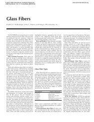
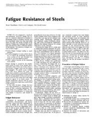
Fig. 4 — <strong>Fatigue</strong> fracture surface: (a) high applied load; (b) low applied load.<br />
20mm<br />
40 mm<br />
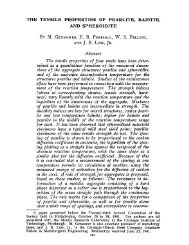
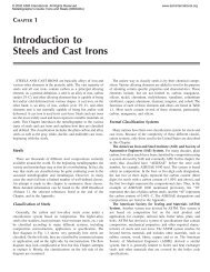
Fig. 5 — Ratcheting marks, indicated<br />
by the arrows, in a SAE 1045 shaft<br />
fractured by fatigue.<br />
da/dN<br />
Plastic deformation<br />
envelope <strong>Crack</strong> tip<br />
Premature contact points<br />
Oxides<br />
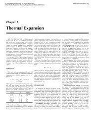
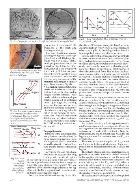
Fig. 7 — <strong>Crack</strong><br />
closure<br />
mechanisms<br />
induced by:<br />
(a) plasticity,<br />
(b) roughness<br />
(c) oxide.<br />
Final failure<br />
Increasing<br />
Paris regime R<br />
Near threshold<br />
K<br />
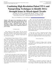
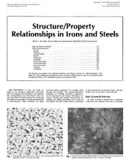
Fig. 6 — Schematic representation of<br />
the R ratio effect on fatigue crack<br />
growth curves. The near threshold,<br />
Paris regime, and final failure<br />
regions are also indicated on the<br />
curves.<br />
<br />
<br />
Plastic zone<br />
(a)<br />
(b)<br />
(c)<br />
properties of the material, dimensions<br />
of the part, and<br />
loading conditions.<br />
The exact fraction of area of<br />
each region depends on the applied<br />
load level. High applied<br />
loads result in a small stable<br />
crack propagation area, as depicted<br />
in Fig. 4. On the other<br />
hand, if lower loads are applied,<br />
the crack will have to grow<br />
longer before the applied stress<br />
intensity factor K, reaches the<br />
fracture toughness value of the<br />
material, resulting in a smaller<br />
area of fast fracture, Fig. 4b.<br />
• Ratcheting marks: Ratcheting<br />
marks are another macroscopic<br />
feature that can be observed in<br />
fatigue fracture surfaces. These<br />
marks originate when multiple<br />
cracks, nucleated at different<br />
points, join together, creating<br />
steps on the fracture surface.<br />
Therefore, counting the number<br />
of ratchet marks is a good indication<br />
of the number of nucleation<br />
sites. Figure 5 presents in<br />
detail some ratchet marks found<br />
on the fracture surface of a large<br />
SAE 1045 rotating shaft fractured<br />
by fatigue.<br />
<strong>Propagation</strong> rates<br />
Similarly to the initiation phase,<br />
many factors can affect long fatigue<br />
crack propagation rates.<br />
Among them, special attention<br />
should be given to effects of load<br />
ratio and the presence of residual<br />
stresses.<br />
Increasing the load ratio has a<br />
tendency to increase the long<br />
crack growth rates in all regions<br />
of the curve plotting fatigue crack growth rate<br />
versus applied stress intensity factor range, or<br />
simply the curve of da/dN versus applied K. Generally<br />
the effect of increasing load ratio is less significant<br />
in the Paris regime than in near-threshold<br />
and near-failure regions, Fig. 6.<br />
Near the threshold stress intensity factor, Kth,<br />
K Keff<br />
(a ) Time<br />
(b) Time<br />
Fig. 8 — Load ratio effect on Keff, in a fatigue cycle: (a)<br />
KminKcl<br />
the effects of R ratio are mainly attributed to crackclosure<br />
effects, in which crack faces contact each<br />
other at an applied Kcl that is higher than the minimum<br />
applied stress intensity factor, Kmin.<br />
Several different mechanisms may contribute<br />
to premature crack closure. One consists of plasticity-induced<br />
closure, represented in Fig. 7a. As<br />
the crack grows, the material that has been previously<br />
permanently deformed within the plastic<br />
zone now forms an envelope of plastic zones in<br />
the wake of the crack front. This leads to displacements<br />
normal to the crack surfaces as the restraint<br />
is relieved. This is no problem while the crack is<br />
open; however as the load decreases, the crack<br />
surfaces touch before the minimum load is<br />
reached, shielding the crack. This type of premature<br />
contact can also occur due to crack wake<br />
roughness and irregularities, Fig. 7b, or by the<br />
presence of corrosion sub-products such as oxides,<br />
Fig. 7c.<br />
As observed in Fig. 8, the effect of closure produces<br />
a reduction in the effective K range because<br />
of the increase in the effective Kmin, reducing<br />
the driving force for fatigue crack growth. The effect<br />
is more significant near the threshold region<br />
because the crack tip opening displacements are<br />
smaller and crack faces are closer to each other.<br />
Additionally, for the same applied K, higher R<br />
ratios increase the applied values of Kmax and Kmin,<br />
increasing Keff.<br />
For most materials, the Paris regime is considered<br />
“closure-free and Kmax-independent” and the<br />
crack growth rates are generally very similar for<br />
tests conducted under different R ratios. Near the<br />
final failure, the effects of R ratio are related to the<br />
higher monotonic fracture component as Kmax approaches<br />
KIC.<br />
Therefore, for the same applied K, Kmax values<br />
are higher for tests conducted under higher applied<br />
R ratios, and consequently, da/dN values are<br />
higher.<br />
The effects of residual stress on fatigue crack<br />
growth are related to alterations in the R ratio and<br />
in the applied K. In other terms, the residual<br />
stresses affect the two parameters that control the<br />
crack driving force, i.e. Kmax and Keff. When a<br />
crack is introduced in a plate subjected to a<br />
residual stress field, a residual stress intensity<br />
factor Kr, arises that can either decrease or increase<br />
the crack driving force parameters.<br />
The superposition principle can also be applied<br />
40 ADVANCED MATERIALS & PROCESSES/MAY 2008<br />
Kap<br />
Kmax<br />
Kmin<br />
Kcl<br />
K<br />
Kap = Keff<br />
Kmax<br />
Kmin<br />
Kcl