Micro- & nano- fluidic research for chemistry, physics - Engineering ...
Micro- & nano- fluidic research for chemistry, physics - Engineering ...
Micro- & nano- fluidic research for chemistry, physics - Engineering ...

Create successful ePaper yourself
Turn your PDF publications into a flip-book with our unique Google optimized e-Paper software.
Downloaded on 12 October 2010<br />
Published on 25 August 2010 on http://pubs.rsc.org | doi:10.1039/C0LC90049D<br />
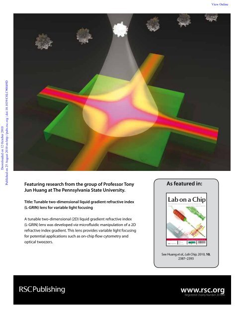
Featuring <strong>research</strong> from the group of Professor Tony<br />
Jun Huang at The Pennsylvania State University.<br />
Title: Tunable two-dimensional liquid gradient refractive index<br />
(L-GRIN) lens <strong>for</strong> variable light focusing<br />
A tunable two-dimensional (2D) liquid gradient refractive index<br />
(L-GRIN) lens was developed via micro<strong>fluidic</strong> manipulation of a 2D<br />
refractive index gradient. This lens provides variable light focusing<br />
<strong>for</strong> potential applications such as on-chip flow cytometry and<br />
optical tweezers.<br />
As featured in:<br />
<strong>Micro</strong>- & <strong>nano</strong>- <strong>fluidic</strong> <strong>research</strong> <strong>for</strong> <strong>chemistry</strong>, <strong>physics</strong>, biology, & bioengineering<br />
www.rsc.org/loc Volume 10 | Number 18 | 21 September 2010 | Pages 2301–2480<br />
ISSN 1473-0197<br />
Günther et al.<br />
Probing small arteries<br />
Love et al.<br />
Gene expression detection<br />
2010 Emerging Investigator Themed Issue<br />
Celebrating<br />
10<br />
Years of publishing<br />
1473-0197(2010)10:18;1-2<br />
See Huang et al., Lab Chip, 2010, 10,<br />
2387–2393<br />
View Online<br />
www.rsc.org<br />
Registered Charity Number 207890
Downloaded by Pennsylvania State University on 14 March 2011<br />
Published on 10 August 2010 on http://pubs.rsc.org | doi:10.1039/C005071G<br />
Tunable two-dimensional liquid gradient refractive index (L-GRIN) lens <strong>for</strong><br />
variable light focusing†‡<br />
Hua Huang, ab Xiaole Mao, bc Sz-Chin Steven Lin, b Brian Kiraly, b Yiping Huang a and Tony Jun Huang* bc<br />
Received 13th April 2010, Accepted 6th July 2010<br />
DOI: 10.1039/c005071g<br />
We report a two-dimensional (2D) tunable liquid gradient refractive index (L-GRIN) lens <strong>for</strong> variable<br />
focusing of light in the out-of-plane direction. This lens focuses a light beam through a liquid medium<br />
with a 2D hyperbolic secant (HS) refractive index gradient. The refractive index gradient is established<br />
in a micro<strong>fluidic</strong> chamber through the diffusion between two fluids with different refractive indices, i.e.<br />
CaCl2 solution and deionized (DI) water. The 2D HS refractive index profile and subsequently the focal<br />
length of the L-GRIN lens can be tuned by changing the ratio of the flow rates of the CaCl2 solution<br />
and DI water. The focusing effect is experimentally characterized through side-view and top-view<br />
image analysis, and the experimental data match well with the results from ray-tracing optical<br />
simulations. Advantages of the 2D L-GRIN lens include simple device fabrication procedure, low fluid<br />
consumption rate, convenient lens-tuning mechanism, and compatibility with existing micro<strong>fluidic</strong><br />
devices. We expect that with further optimizations, this 2D L-GRIN lens can be used in many opticsbased<br />
lab-on-a-chip applications.<br />
Introduction<br />
Tunable microlenses have drawn much attention in recent years<br />
due to their applications in optics-based lab-on-a-chip systems.<br />
Tunable microlenses are capable of focusing incident light,<br />
shifting the focal point, and collecting weak light at the micrometre<br />
scale. They can be further combined with other on-chip<br />
components to per<strong>for</strong>m functions such as biological detection, 1,2<br />
particle manipulation, 3,4 and microscopic bioimaging. 5–7 Thus<br />
far, many methods have been utilized to construct tunable<br />
microlenses. Elastomeric materials, such as polydimethylsiloxane<br />
(PDMS), have been used to <strong>for</strong>m pressureactuated<br />
tunable lens surfaces. 8–10 In recent years, liquids have<br />
become a popular active material in tunable microlenses due to<br />
their advantages of reconfigurability and optically smooth<br />
meniscus surfaces. For example, the electrowetting phenomenon<br />
11–13 has proven to be a promising mechanism <strong>for</strong> changing<br />
the liquid contact angle, and hence the radius of curvature of the<br />
liquid meniscus along with the focal length of the meniscus<br />
microlens. 14,15<br />
Most recently, the concept of reconfigurable liquid–liquid<br />
opto<strong>fluidic</strong> 16–21 devices, such as liquid-core/liquid-cladding<br />
waveguides and light sources, has been developed. 22,23 In these<br />
liquid–liquid opto<strong>fluidic</strong> devices, light can be manipulated purely<br />
a ASIC and System State Key Lab, Department of <strong>Micro</strong>electronics, Fudan<br />
University, Shanghai, 200433, P.R. China<br />
b Department of <strong>Engineering</strong> Science and Mechanics, The Pennsylvania<br />
State University, University Park, PA, 16802, USA. E-mail: junhuang@<br />
psu.edu; Fax: +1 814 865 9974; Tel: +1 814 863 4209<br />
c Department of Bioengineering, The Pennsylvania State University,<br />
University Park, PA, 16802, USA<br />
† Published as part of a special issue dedicated to Emerging Investigators:<br />
Guest Editors: Aaron Wheeler and Amy Herr.<br />
‡ Electronic supplementary in<strong>for</strong>mation (ESI) available: Details of<br />
device fabrication and additional in<strong>for</strong>mation <strong>for</strong> optical ray-tracing<br />
simulation. See DOI: 10.1039/c005071g<br />
View Online<br />
PAPER www.rsc.org/loc | Lab on a Chip<br />
by liquid flow, thus eliminating the need <strong>for</strong> mechanical or<br />
electrical light-manipulation mechanisms. This characteristic<br />
makes liquid–liquid opto<strong>fluidic</strong> devices naturally compatible<br />
with other flow-based lab-on-a-chip components. In this regard,<br />
various tunable opto<strong>fluidic</strong> microlenses based on liquid–liquid<br />
interfaces have been successfully demonstrated. 24 The key to<br />
these liquid–liquid microlenses is to create a hydrodynamically<br />
tunable, curved liquid–liquid interface between two side-by-side<br />
flowing fluids having different refractive indices. The tunable<br />
liquid–liquid interface can then act as a refractive lens to variably<br />
focus light. Previously, we demonstrated a tunable opto<strong>fluidic</strong><br />
cylindrical microlens 24 by using the Dean flow effect 25–28 induced<br />
in a curved microchannel to bend a CaCl2/H2O liquid–liquid<br />
interface. Reconfigurable liquid–liquid lenses which exploited the<br />
convex shape of liquid–liquid interfaces in a micro<strong>fluidic</strong><br />
expansion chamber have also been demonstrated by the Whitesides<br />
group and others. 29,30<br />
The major advantage of these liquid–liquid interface-based<br />
microlenses is that the lenses can be tuned with simple adjustment<br />
of the flow conditions. On the other hand, however, these<br />
liquid–liquid interface-based microlenses present two challenges.<br />
First, diffusion of solute across the fluid–fluid interface tends to<br />
smear the fluid–fluid interface boundary. This <strong>for</strong>ces the lens<br />
design to use a high flow rate to minimize the diffusion time and<br />
maintain a relatively distinct liquid–liquid interface. Second,<br />
most of the current liquid–liquid interface-based microlenses are<br />
only capable of line focusing (1D focusing), instead of point<br />
focusing (2D focusing). This is because current micro<strong>fluidic</strong><br />
technology has not yet been able to provide a means to conveniently<br />
create the precisely controlled, 3D liquid–liquid interface<br />
needed <strong>for</strong> 2D focusing.<br />
To address the first challenge of the liquid–liquid interfacebased<br />
microlenses, we recently introduced a concept called liquid<br />
gradient refractive index (L-GRIN) lens. 31 Instead of attempting<br />
to eliminate diffusion in the micro<strong>fluidic</strong> channel, the L-GRIN<br />
This journal is ª The Royal Society of Chemistry 2010 Lab Chip, 2010, 10, 2387–2393 | 2387
Downloaded by Pennsylvania State University on 14 March 2011<br />
Published on 10 August 2010 on http://pubs.rsc.org | doi:10.1039/C005071G<br />
lens works by taking advantage of the diffusion at the microscale<br />
to <strong>for</strong>m a refractive index gradient in the liquid medium. In the<br />
L-GRIN lens, a high-refractive-index solution was injected sideby-side<br />
with low-refractive-index solutions. The diffusion of<br />
solute between the co-injected flows can <strong>for</strong>m a refractive index<br />
gradient, which can focus light in a way similar to the traditional<br />
gradient refractive index (GRIN) lenses made of solid materials<br />
such as glass or polymers. 32,33 In a micro<strong>fluidic</strong> environment, the<br />
diffusion profile can be conveniently controlled via the manipulation<br />
of the fluid flows. There<strong>for</strong>e, the diffusion profile of the<br />
solute, and hence the refractive index profile within the L-GRIN<br />
lens, can be easily adjusted by changing flow parameters. In our<br />
previous study, the L-GRIN lens concept was proven to be<br />
a useful method <strong>for</strong> variable light focusing. 31 In contrast to the<br />
conventional liquid–liquid interface-based microlenses, the<br />
L-GRIN lens operates through the diffusion in multiple flows,<br />
rather than relying on a clearly defined, curved fluid–fluid<br />
interface. There<strong>for</strong>e the flow consumption rate is much lower in<br />
the L-GRIN lens than in the previously described liquid–liquid<br />
interface-based microlenses. In our previous work, we successfully<br />
used a converging micro<strong>fluidic</strong> channel to implement an<br />
L-GRIN lens which focuses light along the device plane in one<br />
dimension (line focusing).<br />
In this work, we aim to further develop the concept of the<br />
L-GRIN lens to create a tunable 2D L-GRIN lens that addresses<br />
the second challenge faced by the liquid–liquid interface-based<br />
microlenses: 2D light focusing (point focusing). One of the<br />
significant advantages of the L-GRIN lens approach over the<br />
traditional refractive lens is that it relies on the spatial distribution<br />
of the refractive index, rather than the geometry of the lens<br />
surface to focus light. This gives us an opportunity to use<br />
a tunable, 2D refractive index gradient to achieve the 2D light<br />
focusing (which can be conveniently created with a simple planar<br />
micro<strong>fluidic</strong> structure), rather than a complicated 3D liquid–<br />
liquid interface.<br />
Materials and methods<br />
The key to constructing an L-GRIN lens is to <strong>for</strong>m a lightfocusing<br />
hyperbolic secant (HS) refractive index profile. In this<br />
work, the diffusion of CaCl2 between a high refractive index<br />
solution (CaCl 2) and a low refractive index liquid (DI water) is<br />
used to achieve the 2D focusing. Different from the one-dimensional,<br />
line-focusing L-GRIN lens introduced in our previous<br />
work 31 that focuses light along the device plane, the current<br />
device can focus light two-dimensionally (point-focusing) in the<br />
direction that is perpendicular to the device plane (X–Y plane).<br />
An axis-symmetric 2D HS refractive index profile was achieved<br />
using a micro<strong>fluidic</strong> structure shown in Fig. 1(a). Six inlets and<br />
two outlets were connected to an L-GRIN lens chamber to allow<br />
the introduction of fluids with high and low refractive indices.<br />
The two outlets allow the fluids to symmetrically exit the<br />
chamber. In our experiments, a 5 M CaCl 2 solution (n D z 1.445)<br />
was used as the high-refractive-index fluid, and DI water (n D z<br />
1.335) 22 was used as the low-refractive-index fluid. The CaCl 2<br />
solutions were injected into the lens chamber through two center<br />
inlets and converged with the low-refractive-index fluids (H2O)<br />
from side inlets. This allows CaCl2 to diffuse from the CaCl2<br />
solution to DI water to <strong>for</strong>m an axis-symmetric HS distribution<br />
Fig. 1 Principle of the 2D L-GRIN lens. (a) The 2D L-GRIN lens<br />
structure is composed of an L-GRIN lens chamber, two inlets <strong>for</strong> CaCl2<br />
solution, four inlets <strong>for</strong> DI water, and two outlets. The diffusion of CaCl2<br />
inside the L-GRIN lens chamber results in a 2D axis-symmetric hyperbolic<br />
secant (HS) refractive index profile in the X–Y plane, which can be<br />
used to focus the light beam along the Z direction. The lens is bonded to<br />
a glass substrate and a dye chamber is bonded on the opposite side of the<br />
glass substrate <strong>for</strong> visualization purpose. The input light is generated via<br />
a laser diode aligned vertically to the device plane. (b) The side view of the<br />
refractive index distribution in the L-GRIN lens chamber. The focal<br />
point of the 2D L-GRIN lens can be shifted along Z-axis (e.g., from b1 to<br />
b2 by adjusting the refractive index gradient within the liquid medium).<br />
(c) The fluid injection setup of the 2D L-GRIN lens (dye chamber is not<br />
included in this image). (d) A microscopic image of the 2D diffusion<br />
pattern in the lens chamber.<br />
of CaCl2. There<strong>for</strong>e, in the X–Y plane of the lens chamber, the<br />
highest refractive index is achieved in the center, and the<br />
refractive index decreases radially away from the center. This<br />
axial-symmetric HS refractive index profile is <strong>for</strong>med in the lens<br />
chamber and acts as an optical lens to focus light two-dimensionally<br />
as shown in Fig. 1(b).<br />
The HS refractive index distribution in the X–Y plane of the<br />
lens chamber determines the optical properties 34 of the 2D<br />
L-GRIN lens, and is described by the following equation, 35<br />
n 2 (d) ¼ n 2 s +(n 2 o<br />
n 2 s) sech 2 (ad),<br />
View Online<br />
in which n(d) is the refractive index of the solution with a transverse<br />
distance d from the center axis of the lens chamber, n 0 is the<br />
highest refractive index at the center axis of the 2D L-GRIN lens,<br />
ns is the background (lowest) refractive index of the solution, and<br />
a is the gradient parameter determined by the refractive index<br />
2388 | Lab Chip, 2010, 10, 2387–2393 This journal is ª The Royal Society of Chemistry 2010
Downloaded by Pennsylvania State University on 14 March 2011<br />
Published on 10 August 2010 on http://pubs.rsc.org | doi:10.1039/C005071G<br />
profile. With such a 2D refractive index profile in the X–Y device<br />
plane, the vertical light beam can be focused two-dimensionally<br />
along the z-axis. The position of the focal point can be tuned<br />
along the z-direction by changing the HS refractive index profile<br />
(Fig. 1(b)), which can be achieved by adjusting the flow rate<br />
ratios between the high-refractive-index (CaCl2) and the lowrefractive-index<br />
fluids (H2O).<br />
The experimental setup is shown in a 3D schematic in Fig. 1(a).<br />
The incident light from a 532 nm laser diode was aligned to the<br />
central axis of the 2D L-GRIN lens structure and shined normally<br />
(z direction) on the lens chamber. In order to observe the<br />
focusing effect of the 2D L-GRIN lens, the device had three<br />
layers, including (from bottom to top) the 2D L-GRIN lens<br />
chamber (thickness ¼ 155 mm, width and length ¼ 200 mm), the<br />
glass substrate layer (thickness ¼ 220 mm), and the dye chamber<br />
(thickness ¼ 155 mm, width and length ¼ 200 mm). The dye<br />
chamber was filled with a fluorescent dye solution (Rhodamine<br />
B, 10 mg ml 1 ) so that the trajectories of the focused light beams<br />
could be observed during the focusing process. The 2D L-GRIN<br />
lens chamber and the dye chamber were made using standard<br />
soft lithography and mold replica procedures 36 (please see ESI†<br />
<strong>for</strong> detailed fabrication procedure). The fluids were injected into<br />
the L-GRIN lens chamber using precision syringe pumps (KD<br />
Scientific 210). The experiments were conducted on an inverted<br />
optical microscope (Nikon TE 2000U), with the images taken by<br />
a color digital camera (Nikon D50) mounted on the microscope.<br />
Fig. 1(c) illustrates the fluid injection setup of the 2D L-GRIN<br />
lens (dye chamber is not included in this image), and Fig. 1(d)<br />
shows a microscopic image of the 2D diffusion pattern in the lens<br />
chamber (food dye was added into the CaCl2 solution to highlight<br />
the diffusion pattern).<br />
To evaluate the per<strong>for</strong>mance of this 2D L-GRIN lens and<br />
optimize the experimental parameters, two types of numerical<br />
simulations were conducted. First, computational fluid dynamics<br />
(CFD) simulations were done with a commercial software<br />
package (ESI-CFD) and were used <strong>for</strong> calculating the CaCl 2<br />
concentration distribution, which is linearly proportional to the<br />
refractive index distribution in the L-GRIN lens. Based on the<br />
data obtained from the CFD simulation, an optical ray-tracing<br />
simulation was per<strong>for</strong>med to simulate the trajectories of the light<br />
beams during the focusing process. The ray-tracing algorithm <strong>for</strong><br />
an HS refractive index gradient was based on the ABCD law and<br />
was implemented with a MATLAB program. The analysis of the<br />
experimental result was conducted using an image analysis<br />
package ImageJ. 37<br />
Results and discussions<br />
In order to <strong>for</strong>m the axis-symmetric refractive index profile in the<br />
lens chamber, the CaCl2 solution was co-injected with the DI<br />
water into the lens chamber from two opposite directions as<br />
shown in Fig. 2(a). The DI water streams compress the CaCl2<br />
solution from both sides, and CaCl 2 molecules diffuse across the<br />
interface of the two fluids. Fig. 2(a) shows the simulated<br />
concentration distribution of CaCl 2 during the flow injection<br />
process. The simulation result indicates that upon contacting the<br />
DI water, CaCl2 starts to diffuse from the CaCl2 solution into DI<br />
water. After two opposite CaCl2 solution/DI water co-flows<br />
enter the lens chamber, they are <strong>for</strong>ced to change their flow<br />
View Online<br />
directions and exit the chamber from two symmetric outlets. The<br />
diffusion of CaCl 2 in this process results in the <strong>for</strong>mation of<br />
a light-focusing, 2D refractive index gradient in the lens<br />
chamber.<br />
To evaluate the focusing capability of this 2D refractive index<br />
gradient, the refractive index distribution (Fig. 2(b)) within the<br />
lens chamber was plotted using the CaCl2 concentration distribution<br />
obtained from the CFD result in Fig. 2(a). Fig. 2(b)<br />
indicates that the refractive index in the lens chamber shows an<br />
axis-symmetric pattern, in which refractive index is higher in the<br />
center and lower towards the outer edges. We further plot the line<br />
profiles (Fig. 2(c)) of the refractive index within the lens chamber,<br />
with b increasing from 0 to 90 with a 5 increment (b is defined<br />
in Fig. 2(b)). It is found that, except <strong>for</strong> the lines near the<br />
directions of the inlets and outlets (b ¼ 0 and 90 ), most of the<br />
refractive index profiles follow an HS distribution and match<br />
well with each other. This characteristic ensures that nearly all of<br />
the incoming light is focused to a single focal point. In order to<br />
investigate the influence of fluid injection parameters on the<br />
refractive index profile, and hence the position of the focal point,<br />
the refractive index profiles of CaCl2 at different fluid injection<br />
conditions were simulated. Fig. 2(d) shows the change of diagonal<br />
concentration distribution (b ¼ 45 ) of CaCl 2 in the fluid<br />
chamber with decreasing DI water/CaCl 2 flow rate ratio (from<br />
bottom to top, DI water flow rate ¼ 8.0, 6.4, 4.8, 3.2, 2.4, 1.6, and<br />
0.8 ml min 1 , respectively; CaCl2 solution flow rate ¼ 8.0 ml min 1<br />
<strong>for</strong> all cases).<br />
Fig. 2(d) suggests that the HS refractive index distribution<br />
within the lens chamber can be conveniently adjusted by varying<br />
the fluid rates. Further analysis in Fig. 2(e) shows the relation<br />
between the change of refractive index contrast (difference<br />
between the maximum and minimum of the refractive index<br />
profile) and the change of the fluid rate ratio (DI water/CaCl 2<br />
solution). Since a change of the refractive index contrast corresponds<br />
to a linear change in the focal length, Fig. 2(e) suggests<br />
that the focal length does not linearly increase with the flow rate<br />
ratio—it is most responsive when the flow rate ratio is low (0.1–<br />
0.5) and becomes less responsive when the flow rate ratio is close<br />
to 1.0. This observation is useful in determining the operation<br />
parameters of the 2D L-GRIN lens.<br />
Fig. 3(a–c) are the CFD simulated refractive index distributions<br />
inside the lens chamber at different flow conditions<br />
(DI water flow rate ¼ 8.0 ml min 1 , 3.2 ml min 1 , and 2.4 ml min 1 ,<br />
respectively, and CaCl 2 solution flow rate ¼ 8.0 ml min 1 in all<br />
three cases). These simulated 2D refractive index distributions<br />
can be fitted well with a 2D HS profile (please see the ESI† <strong>for</strong><br />
details), and the 2D-fitted HS profiles were used <strong>for</strong> the raytracing<br />
simulation to evaluate the per<strong>for</strong>mance of the 2D<br />
L-GRIN lens <strong>for</strong> light focusing. The ray-tracing simulations<br />
show the trajectories of light beams in the three-layer structure<br />
previously introduced (the L-GRIN lens chamber, the glass<br />
substrate, and the dye chamber, respectively). The ray-tracing<br />
simulations were conducted using the corresponding flow rate<br />
parameters from Fig. 3(a–c), and the simulated light-focusing<br />
patterns (in X–Z cross-sectional plane) are shown in Fig. 3(d–f).<br />
The results show that inside the liquid medium within the L-<br />
GRIN lens chamber, collimated light beams from the laser<br />
source bend gradually towards the central optical axis. After<br />
exiting the 2D L-GRIN lens, the light propagates through the<br />
This journal is ª The Royal Society of Chemistry 2010 Lab Chip, 2010, 10, 2387–2393 | 2389
Downloaded by Pennsylvania State University on 14 March 2011<br />
Published on 10 August 2010 on http://pubs.rsc.org | doi:10.1039/C005071G<br />
View Online<br />
Fig. 2 (a) The simulated CaCl2 concentration distribution in the fluid chamber (CaCl2 flow rate ¼ 8 ml min 1 and DI water flow rate ¼ 3.2 ml min 1 ). (b)<br />
The refractive index distribution in the lens chamber derived from the CFD simulation. (c) The line profile of refractive index in the X–Y plane along<br />
different directions (from 0 to 90 with a 5 increment). (d) Change of the refractive index profile with different fluid rates (b ¼ 45 ). (e) The change of<br />
the refractive index contrast is not linear with respect to the change of the flow rate ratio between water and CaCl 2 solution.<br />
Fig. 3 Ray-tracing simulation of the variable light focusing process. (a–c) The CFD simulated 2D HS refractive index profile within the lens chamber<br />
<strong>for</strong> different flow conditions (DI water flow rate ¼ 8.0 ml min 1 , 3.2 ml min 1 , and 2.4 ml min 1 , respectively, and CaCl 2 solution flow rate ¼ 8.0 ml min 1 in<br />
all three cases). (d–f) The simulated trajectories of the light beam during the focusing process with three different fluid flow conditions shown in (a–c),<br />
respectively. The structure in the simulation is composed of three parts: the L-GRIN lens, the glass substrate, and the dye chamber.<br />
2390 | Lab Chip, 2010, 10, 2387–2393 This journal is ª The Royal Society of Chemistry 2010
Downloaded by Pennsylvania State University on 14 March 2011<br />
Published on 10 August 2010 on http://pubs.rsc.org | doi:10.1039/C005071G<br />
glass substrate and converges within the dye chamber at the focal<br />
point. Changing the fluid injection ratios results in a change in<br />
refractive index gradient (Fig. 3(a–c)), causing the light to<br />
converge differently and resulting in a shift of the focal point<br />
inside the dye chamber along the z-direction (Fig. 3(d–f)). These<br />
simulated results suggest that the focal length increases when the<br />
flow rate of DI water decreases. The simulations also predict the<br />
tuning range of the focal point along the z-axis to be 130 mm.<br />
In order to characterize the per<strong>for</strong>mance of the L-GRIN lens,<br />
a series of experiments were conducted with the experimental<br />
setup <strong>for</strong> side-view ray-tracing illustrated in Fig. 4(a). The device<br />
used <strong>for</strong> experimental characterization, as previously described,<br />
consists of three components: the L-GRIN lens, the glass<br />
substrate, and the dye chamber. The collimated light beam from<br />
a semiconductor laser diode (532 nm) was shined on the X–Y<br />
plane of the L-GRIN lens chamber along the z-direction. After<br />
exiting the L-GRIN lens chamber, the light enters the dye<br />
chamber through the glass layer, where its trajectory can be<br />
visualized by the fluorescent emission of Rhodamine dyes (excitation<br />
wavelength of 532 nm and emission wavelength of 560<br />
nm). It should be noted that the per<strong>for</strong>mance of the L-GRIN lens<br />
can be affected by temperature. Temperature has an influence on<br />
the refractive index gradient profile of the L-GRIN lens because<br />
both the diffusion coefficient of the solute (CaCl 2) and the<br />
refractive index of the liquid medium vary with temperature. 38,39<br />
There<strong>for</strong>e, changes in temperature can result in a variation of the<br />
lens per<strong>for</strong>mance, such as a variation in the lens’ focal length.<br />
Fig. 4 Experimental characterization of the variable light focusing<br />
process. (a) The device includes three layers (i.e. the L-GRIN lens<br />
chamber, the glass substrate, and the dye chamber <strong>for</strong> visualization of the<br />
focused light beams). (b–d) Change of the light-focusing patterns and<br />
shifting of the focal point positions with different flow rate conditions (DI<br />
water flow rate ¼ 8.0 ml min 1 , 3.2 ml min 1 , and 2.4 ml min 1 , respectively,<br />
and CaCl2 solution flow rate ¼ 8.0 ml min 1 in all three cases) are visualized<br />
in the dye chamber. (e) Light intensity plots along the z-axis,<br />
corresponding to the images in (b–d), indicate the shift of the focal point<br />
during the experiments.<br />
View Online<br />
Throughout our experiments, the fluid temperatures remained<br />
constant ( 25 C) and there<strong>for</strong>e the experimental results of the<br />
L-GRIN lens were highly repeatable. In the future studies, we<br />
will use CFD and ray-tracing simulations to investigate the<br />
influence of changes in the solute diffusion coefficient and<br />
refractive index of the liquid medium, caused by the temperature<br />
variation, on the per<strong>for</strong>mance of the L-GRIN lens.<br />
The side-view ray-tracing experiments were conducted with<br />
the same parameters that were used in the CFD and ray-tracing<br />
simulations in Fig. 3 (DI water flow rate ¼ 8.0 ml min 1 , 3.2 ml<br />
min 1 , and 2.4 ml min 1 , respectively; CaCl 2 solution flow rate ¼<br />
8.0 ml min 1 ). Fig. 4(b–d) illustrate the trajectories of the light<br />
beams within the dye chamber. The results show that the light<br />
beam can be well focused to a point whose position can be shifted<br />
along the z-axis with different flow rates. Fig. 4(e) shows the light<br />
intensity plots along the z-axis, and the maximum intensity<br />
indicates the position of focal point. The results show that the<br />
focal point can be shifted approximately 120 mm, which matches<br />
well with the simulated result in Fig. 3 ( 130 mm). For this 2D L-<br />
GRIN lens, the establishment of the refractive index gradient <strong>for</strong><br />
light focusing relies solely on the diffusion of the solute (CaCl2)<br />
between high and low refractive-index solutions; this process is<br />
affected by multiple factors such as diffusion coefficient, fluid<br />
viscosity, and compliance of the fluid injection tubings. Experimentally,<br />
we have observed that the transition between different<br />
operation states (different focal lengths) can be achieved within<br />
2–3 seconds. This observation is in agreement with our previous<br />
work on L-GRIN lens with 1D focusing ability. 31 Additionally,<br />
once the fluid injection rates of the device are set and the<br />
refractive index profile is stabilized, the lens can remain stable <strong>for</strong><br />
a long period of time (several hours or more).<br />
From the experimental results, the maximum numerical<br />
aperture (NA ¼ nsin q, where n, the refractive index in the dye<br />
chamber, is approximately 1.33, and q is half of the focused beam<br />
exit angle) is measured to be 0.249 in Fig. 4(b). The NA of a lens<br />
is one of the most important parameters in evaluating its<br />
focusing ability, and a high NA is often required <strong>for</strong> optical<br />
trapping 40,41 and high-resolution imaging. Further improvement<br />
of the NA can be achieved by increasing the depth of the<br />
L-GRIN lens chamber (currently 155 mm) or the refractive index<br />
contrast between the two fluids; both alterations would lead to<br />
more dramatic bending of the light beams.<br />
We observe through both simulations and experiments that the<br />
L-GRIN lens shows some aberration (light beams not perfectly<br />
focused to a single focal point). We believe this is due to the fact<br />
that the profiles of the refractive indices achieved with current<br />
L-GRIN lens <strong>fluidic</strong> channel design are slightly different from the<br />
theoretical hyperbolic secant profiles. In order to minimize the<br />
aberration and to improve the per<strong>for</strong>mance of the L-GRIN lens,<br />
further geometric optimization of the L-GRIN lens’ <strong>fluidic</strong><br />
channel is needed to achieve ideal refractive index profiles to<br />
perfectly focus all the light beams to a single focal point.<br />
In order to further characterize the focusing per<strong>for</strong>mance of<br />
the 2D L-GRIN lens, we characterized the top-view images of the<br />
focused light spots in the dye chamber (X–Y plane) at different<br />
flow conditions. Fig. 5(a) shows the unfocused light distribution<br />
in the dye chamber when the 2D L-GRIN lens is not operational<br />
(stagnant flow in the lens chamber). Fig. 5(b–d) show the<br />
transition of the light-focusing pattern from under-focused to<br />
This journal is ª The Royal Society of Chemistry 2010 Lab Chip, 2010, 10, 2387–2393 | 2391
Downloaded by Pennsylvania State University on 14 March 2011<br />
Published on 10 August 2010 on http://pubs.rsc.org | doi:10.1039/C005071G<br />
Fig. 5 Top-view images of the light spots in the dye chamber after the<br />
light passing through the 2D L-GRIN lens at different flow conditions.<br />
(a) Unfocused (stagnant flow); (b–d) from under-focused to well-focused<br />
light. DI water flow rate ¼ 6.4 ml min 1 , 4.8 ml min 1 , and 3.2 ml min 1 ,<br />
respectively; and CaCl2 solution flow rate ¼ 8.0 ml min 1 . (e–h) The 2D<br />
light intensity distribution corresponding to (a–d), respectively.<br />
well-focused at different flow injection conditions (DI water flow<br />
rates ¼ 6.4 ml min 1 , 4.8 ml min 1 , and 3.2 ml min 1 , respectively;<br />
CaCl2 solution flow rates ¼ 8.0 ml min 1 ). These images provide<br />
direct proof of the tunable 2D light focusing. From these images<br />
it is observed that the shape of the light spot is similar to the<br />
refractive index distribution in the lens chamber. The minimum<br />
spot size (Fig. 5(d)) achieved with this 2D L-GRIN lens<br />
is 20 mm, which is suitable <strong>for</strong> applications such as on-chip flow<br />
cytometry. 24,42 Fig. 5(e–h) show the changes of the 2D intensity<br />
distribution of the light beam at different focusing conditions.<br />
The light intensity is increased by a factor of 4.5 from the nonfocused<br />
condition (Fig. 5(e)) to the well-focused one (Fig. 5(h)).<br />
It is noted that the shape of the focused light beam obtained with<br />
this 2D L-GRIN lens is similar to a square with stronger intensity<br />
distribution along the two diagonal directions, which is different<br />
from the circular light spots obtained with most existing 2D<br />
lenses. Further improvement of the 2D refractive index distribution<br />
is needed to achieve a more desirable light-focusing<br />
pattern. This can be achieved by optimizing the geometry of the<br />
L-GRIN lens chamber.<br />
In this article, we have demonstrated that three different lens<br />
states (focal lengths and numerical apertures) can be achieved<br />
with three different sets of fluid injection parameters. These oneto-one<br />
lens state/fluid injection parameter correlations can serve<br />
as a preliminary look-up table <strong>for</strong> lens operation. A more<br />
comprehensive and detailed look-up table can be established by<br />
further correlating different lens states (focal lengths and<br />
numerical apertures) with different flow injection rates through<br />
simulation and experimental measurement. We have experimentally<br />
demonstrated that our L-GRIN lens is highly repeatable,<br />
and one should always expect the same lens state (same<br />
focal length and numerical aperture) with a specific set of fluid<br />
injection parameters, regardless of the initial state of the lens.<br />
Additionally, the lens is very stable over time. There<strong>for</strong>e, we<br />
believe that our L-GRIN lens is capable of delivering reliable,<br />
repeatable per<strong>for</strong>mance.<br />
Conclusions<br />
In this article, we introduced a tunable 2D L-GRIN microlens<br />
which can be used to two-dimensionally focus light normally<br />
incident on the device plane. By utilizing the diffusion<br />
phenomena in fluids, this L-GRIN lens can achieve 2D light<br />
focusing with a simple, planar micro<strong>fluidic</strong> chamber, rather than<br />
involving complex three-dimensional microstructures used in<br />
previously reported 2D microlenses. The 2D L-GRIN lens can be<br />
conveniently fabricated using standard soft-lithography and can<br />
be readily integrated with other micro<strong>fluidic</strong> devices. The 2D L-<br />
GRIN lens also has other advantages such as low flow<br />
consumption and a simple lens control mechanism. Simply by<br />
adjusting the fluid injection ratio, the focal point of this lens can<br />
be varied along the out-of-plane direction (z-direction). These<br />
advantages make the 2D L-GRIN lens suitable <strong>for</strong> a wide variety<br />
of on-chip applications such as on-chip detection, and potentially<br />
the manipulation of particles/molecules. 43–50 The 2D L-GRIN<br />
lens, as with the 1D L-GRIN lens introduced in our previous<br />
work, 31 represents a novel concept by utilizing the precise<br />
manipulation of refractive index distribution in micro<strong>fluidic</strong><br />
environments <strong>for</strong> on-chip light manipulation. We envision that<br />
with further developments, this concept can facilitate a new class<br />
of opto<strong>fluidic</strong> devices <strong>for</strong> on-chip optical applications.<br />
Acknowledgements<br />
This <strong>research</strong> was supported by US Department of Agriculture<br />
(USDA/NRI), National Science Foundation, Air Force Office of<br />
Scientific Research (AFOSR), and the Penn State Center <strong>for</strong><br />
Nanoscale Science (MRSEC). Components of this work were<br />
conducted at the PennState node of the NSF-funded National<br />
Nanotechnology Infrastructure Network.<br />
References<br />
View Online<br />
1 A. Llobera, V. J. Cadarso, M. Darder, C. Domınguez and<br />
C. F. Sanchez, Lab Chip, 2008, 8, 1185–1190.<br />
2 S. Mandal and D. Erickson, Opt. Express, 2008, 16, 1623–1631.<br />
2392 | Lab Chip, 2010, 10, 2387–2393 This journal is ª The Royal Society of Chemistry 2010
Downloaded by Pennsylvania State University on 14 March 2011<br />
Published on 10 August 2010 on http://pubs.rsc.org | doi:10.1039/C005071G<br />
3 F. Arai, C. Ng, H. Maruyama, A. Ichikawa, H. El-Shimy and<br />
T. Fukuda, Lab Chip, 2005, 5, 1399–1403.<br />
4 B. S. Schmidt, A. H. J. Yang, D. Erickson and M. Lipson, Opt.<br />
Express, 2007, 15, 14322–14334.<br />
5 X. Heng, D. Erickson, L. R. Baugh, Z. Yaqoob, P. W. Sternberg,<br />
D. Psaltis and C. Yang, Lab Chip, 2006, 6, 1274–1276.<br />
6 S. Pang, X. Cui, J. DeModena, Y. M. Wang, P. Sternberg and<br />
C. Yang, Lab Chip, 2010, 10, 411–414.<br />
7 J. Wu, X. Cui, L. M. Lee and C. Yang, Opt. Express, 2008, 16,<br />
15595–15602.<br />
8 G. Beadie, M. L. Sandrock, M. J. Wiggins, R. S. Lepkowicz,<br />
J. S. Shirk, M. Ponting, Y. Yang, T. Kazmierczak, A. Hiltner and<br />
E. Baer, Opt. Express, 2008, 16, 11847–11857.<br />
9 K. H. Jeong, G. Liu, N. Chronis and L. P. Lee, Opt. Express, 2004, 12,<br />
2494–2500.<br />
10 N. Chronis, G. L. Liu, K. Jeong and L. P. Lee, Opt. Express, 2003, 11,<br />
2370–2378.<br />
11 M. G. Pollack, R. B. Fair and A. D. Shenderov, Appl. Phys. Lett.,<br />
2000, 77, 1725–1726.<br />
12 S. K. Fan, H. Yang, T. T. Wang and W. Hsu, Lab Chip, 2007, 7,<br />
1330–1335.<br />
13 R. A. Hayes and B. J. Feenstra, Nature, 2003, 425, 383–385.<br />
14 F. Krogmann, R. Shaik, L. Lasinger, W. M€onch and H. Zappe, Sens.<br />
Actuators, A, 2008, 143, 129–135.<br />
15 S. Kuiper and B. H. W. Hendriks, Appl. Phys. Lett., 2004, 85,<br />
1128–1130.<br />
16 H. Schmidt and A. R. Hawkins, <strong>Micro</strong>fluid. Nanofluid., 2008, 4, 3–16.<br />
17 A. R. Hawkins and H. Schmidt, <strong>Micro</strong>fluid. Nanofluid., 2008, 4,<br />
17–32.<br />
18 D. Psaltis, S. R. Quake and C. Yang, Nature, 2006, 442, 381–386.<br />
19 C. Monat, P. Domachuk and B. J. Eggleton, Nat. Photonics, 2007, 1,<br />
106–114.<br />
20 J. Shi, Z. Stratton, S. C. S. Lin, H. Huang and T. J. Huang,<br />
<strong>Micro</strong>fluid. Nanofluid., 2010, 9, 313–318.<br />
21 M. I. Lapsley, S. C. S. Lin, X. Mao and T. J. Huang, Appl. Phys. Lett.,<br />
2009, 95, 083507.<br />
22 D. B. Wolfe, R. S. Conroy, P. Garstecki, B. T. Mayers,<br />
M. A. Fischbach, K. E. Paul, M. Prentiss and G. M. Whitesides,<br />
Proc. Natl. Acad. Sci. U. S. A., 2004, 101, 12434–12438.<br />
23 D. V. Vezenov, B. T. Mayers, D. B. Wolfe and G. M. Whitesides,<br />
Appl. Phys. Lett., 2005, 86, 041104.<br />
24 X. Mao, J. R. Waldeisen and T. J. Huang, Lab Chip, 2007, 7,<br />
1260–1262.<br />
25 P. B. Howell, Jr, D. R. Mott, J. P. Golden and F. S. Ligler, Lab Chip,<br />
2004, 4, 663–669.<br />
26 D. Di Carlo, D. Irimia, R. G. Tompkins and M. Toner, Proc. Natl.<br />
Acad. Sci. U. S. A., 2007, 104, 18892–18897.<br />
27 A. P. Sudarsan and V. M. Ugaz, Proc. Natl. Acad. Sci. U. S. A., 2006,<br />
103, 7228–7233.<br />
View Online<br />
28 Y. Yamaguchi, F. Takagi, K. Yamashita, H. Nakamura, H. Maeda,<br />
K. Sotowa, K. Kusakabe, Y. Yamasaki and S. Morooka, AIChE J.,<br />
2004, 50, 1530–1535.<br />
29 S. K. Y. Tang, C. A. Stan and G. M. Whitesides, Lab Chip, 2008, 8,<br />
395–401.<br />
30 C. Song, N. T. Nguyen, S. H. Tan and A. K. Asundi, Lab Chip, 2009,<br />
9, 1178–1184.<br />
31 X. Mao, S. C. S. Lin, M. I. Lapsley, J. Shi, B. K. Juluri and<br />
T. J. Huang, Lab Chip, 2009, 9, 2050–2058.<br />
32 M. Zickar, W. Noell, C. Marxer and N. de Rooij, Opt. Express, 2006,<br />
14, 4237–4249.<br />
33 G. Beadie, J. S. Shirk, A. Rosenberg, P. A. Lane, E. Fleet,<br />
A. R. Kamdar, Y. Jin, M. Ponting, T. Kazmierczak, Y. Yang,<br />
A. Hiltner and E. Baer, Opt. Express, 2008, 16, 11540–11547.<br />
34 C. Gomez-Reino, M. V. Perez and C. Bao, in Gradient-Index Optics:<br />
Fundamentals and Applications, ed. C. Gomez-Reino, M. V. Perez and<br />
C. Bao, Springer, Heidelberg, 2002, pp. 127–131.<br />
35 B. K. Juluri, S. C. S. Lin, T. R. Walker, L. Jensen and T. J. Huang,<br />
Opt. Express, 2009, 17, 2997–3006.<br />
36 Y. N. Xia and G. M. Whitesides, Annu. Rev. Mater. Sci., 1998, 28,<br />
153–184.<br />
37 http://rsbweb.nih.gov/ij/.<br />
38 J. R. Welty, C. E. Wicks, R. E. Wilson and G. L. Rorrer, in<br />
Fundamentals of Momentum, Heat, and Mass Transfer, ed. J. R.<br />
Welty, C. E. Wicks, R. E. Wilson and G. L. Rorrer, John Wiley &<br />
Sons, Inc., 5th edn, 2008, pp. 415–416.<br />
39 S. K. Y. Tang, B. T. Mayers, D. V. Vezenov and G. M. Whitesides,<br />
Appl. Phys. Lett., 2006, 88, 061112.<br />
40 J. T. Blakely, R. Gordon and D. Sinton, Lab Chip,2008,8, 1350–1356.<br />
41 C. Liberale, P. Minzioni, F. Bragheri, F. De Angelis, E. Di Fabrizio<br />
and I. Cristiani, Nat. Photonics, 2007, 1, 723–727.<br />
42 X. Mao, S. C. S. Lin, C. Dong and T. J. Huang, Lab Chip, 2009, 9,<br />
1583–1589.<br />
43 T. D. Rane, C. M. Puleo, K. J. Liu, Y. Zhang, A. P. Lee and<br />
T. H. Wang, Lab Chip, 2010, 10, 161–164.<br />
44 H. Y. Hsu, A. T. Ohta, P. Y. Chiou, A. Jamshidi, S. L. Neale and<br />
M. C. Wu, Lab Chip, 2010, 10, 165–172.<br />
45 S. K€uhn, E. J. Lunt, B. S. Philips, A. R. Hawkins and H. Schmidt, Lab<br />
Chip, 2010, 10, 189–194.<br />
46 S. K€uhn, P. Measor, E. J. Lunt, B. S. Phillips, D. W. Deamer,<br />
A. R. Hawkins and H. Schmidt, Lab Chip, 2009, 9, 2212–2216.<br />
47 Y. N. Wang, Y. J. Kang, D. Y. Xu, L. Barnett, S. A. Kalams, D. Y. Li<br />
and D. Q. Li, Lab Chip, 2008, 8, 309–315.<br />
48 J. Shi, D. Ahmed, X. Mao, S. C. S. Lin and T. J. Huang, Lab Chip,<br />
2009, 9, 2890–2895.<br />
49 J. Shi, H. Huang, Z. Stratton, A. Lawit, Y. Huang and T. J. Huang,<br />
Lab Chip, 2009, 9, 3354–3359.<br />
50 J. Shi, X. Mao, D. Ahmed, A. Colletti and T. J. Huang, Lab Chip,<br />
2008, 8, 221–223.<br />
This journal is ª The Royal Society of Chemistry 2010 Lab Chip, 2010, 10, 2387–2393 | 2393