EtherCAT Slave Implementation Guide
EtherCAT Slave Implementation Guide
EtherCAT Slave Implementation Guide

Create successful ePaper yourself
Turn your PDF publications into a flip-book with our unique Google optimized e-Paper software.
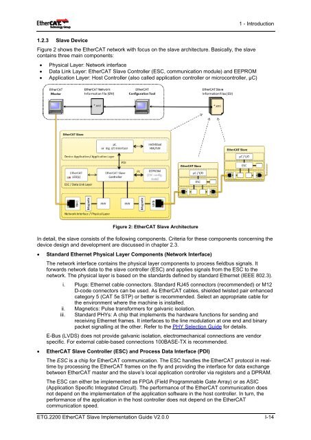
1.2.3 <strong>Slave</strong> Device<br />
Figure 2 shows the <strong>EtherCAT</strong> network with focus on the slave architecture. Basically, the slave<br />
contains three main components:<br />
1 - Introduction<br />
• Physical Layer: Network interface<br />
• Data Link Layer: <strong>EtherCAT</strong> <strong>Slave</strong> Controller (ESC, communication module) and EEPROM<br />
• Application Layer: Host Controller (also called application controller or microcontroller, µC)<br />
Figure 2: <strong>EtherCAT</strong> <strong>Slave</strong> Architecture<br />
In detail, the slave consists of the following components. Criteria for these components concerning the<br />
device design and development are discussed in chapter 2.3.<br />
• Standard Ethernet Physical Layer Components (Network Interface)<br />
The network interface contains the physical layer components to process fieldbus signals. It<br />
forwards network data to the slave controller (ESC) and applies signals from the ESC to the<br />
network. The physical layer is based on the standards defined by standard Ethernet (IEEE 802.3).<br />
i. Plugs: Ethernet cable connectors. Standard RJ45 connectors (recommended) or M12<br />
D-code connectors can be used. As <strong>EtherCAT</strong> cables, shielded twisted pair enhanced<br />
category 5 (CAT 5e STP) or better is recommended. Select an appropriate cable for<br />
the environment where the machine is installed.<br />
ii. Magnetics: Pulse transformers for galvanic isolation.<br />
iii. Standard PHYs: A chip that implements the hardware functions for sending and<br />
receiving Ethernet frames. It interfaces to the line modulation at one end and binary<br />
packet signalling at the other. Refer to the PHY Selection <strong>Guide</strong> for details.<br />
E-Bus (LVDS) does not provide galvanic isolation, electromechanical connections are vendor<br />
specific. For external cable-based connections 100BASE-TX is recommended.<br />
• <strong>EtherCAT</strong> <strong>Slave</strong> Controller (ESC) and Process Data Interface (PDI)<br />
The ESC is a chip for <strong>EtherCAT</strong> communication. The ESC handles the <strong>EtherCAT</strong> protocol in realtime<br />
by processing the <strong>EtherCAT</strong> frames on the fly and providing the interface for data exchange<br />
between <strong>EtherCAT</strong> master and the slave’s local application controller via registers and a DPRAM.<br />
The ESC can either be implemented as FPGA (Field Programmable Gate Array) or as ASIC<br />
(Application Specific Integrated Circuit). The performance of the <strong>EtherCAT</strong> communication does<br />
not depend on the implementation of the application software in the host controller. In turn, the<br />
performance of the application in the host controller does not depend on the <strong>EtherCAT</strong><br />
communication speed.<br />
ETG.2200 <strong>EtherCAT</strong> <strong>Slave</strong> <strong>Implementation</strong> <strong>Guide</strong> V2.0.0 I-14