781SS-871SS 97-6642 0410 - ETS Company Pressure Washers ...
781SS-871SS 97-6642 0410 - ETS Company Pressure Washers ...
781SS-871SS 97-6642 0410 - ETS Company Pressure Washers ...

You also want an ePaper? Increase the reach of your titles
YUMPU automatically turns print PDFs into web optimized ePapers that Google loves.
MODELS <strong>781SS</strong>,<br />
<strong>871SS</strong>, 921SS<br />
OPERATING INSTRUCTIONS<br />
AND PARTS MANUAL<br />
Thank you for purchasing a Hotsy <strong>Pressure</strong> Washer. This manual covers the operation and maintenance<br />
of your pressure washer. All information in this manual is based on the latest product information<br />
available at the time of printing. Hotsy, Inc. reserves the right to make changes at any time without<br />
incurring any obligation.<br />
Read instructions carefully before attempting to assemble, install, operate or service this pressure<br />
washer. Failure to comply with instructions could result in personal injury and/or property damage!<br />
LISTED<br />
®<br />
SERIAL NUMBER:<br />
DATE PURCHASED:<br />
FOR SALES AND SERVICE, PLEASE CONTACT:
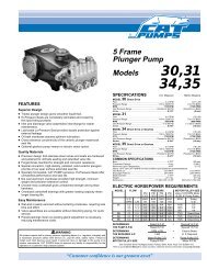
<strong>781SS</strong> SPECIFICATIONS<br />
● Pump Volume At Pump Head: 2.5 GPM/150 GPH<br />
● Pump <strong>Pressure</strong> At Pump Head: 2000 PSI<br />
● Burner Type: Fuel Oil Fired, 248,500 BTU/Hr.<br />
● Burner Fuel <strong>Pressure</strong>: 140 PSI<br />
● Machine Voltage: 6 HP Robin Subaru, Manual Start<br />
● Machine Weight: 287 Lbs.<br />
● Shipping Weight: 326 Lbs.<br />
● Exhaust Stack Size: 8"<br />
● Machine Dimensions: Length=48", Width=27", Height=42.5"<br />
921SS SPECIFICATIONS<br />
● Pump Volume At Pump Head: 3.0 GPM/180 GPH<br />
● Pump <strong>Pressure</strong> At Pump Head: 3000 PSI<br />
● Burner Type: Fuel Oil Fired, 248,500 BTU/Hr.<br />
● Burner Fuel <strong>Pressure</strong>: 140 PSI<br />
● Machine Voltage: 9 HP Robin Subaru, Manual Start<br />
● Machine Weight: 385 Lbs.<br />
● Shipping Weight: 415 Lbs.<br />
● Exhaust Stack Size: 8"<br />
● Machine Dimensions: Length=47", Width=31", Height=49"<br />
<strong>871SS</strong> SPECIFICATIONS<br />
● Pump Volume At Pump Head: 2.71 GPM/162.6 GPH<br />
● Pump <strong>Pressure</strong> At Pump Head: 2400 PSI<br />
● Burner Type: Fuel Oil Fired, 248,500 BTU/Hr.<br />
● Burner Fuel <strong>Pressure</strong>: 140 PSI<br />
● Machine Voltage: 7 HP Robin Subaru, Manual Start<br />
● Machine Weight: 291 Lbs.<br />
● Shipping Weight: 330 Lbs.<br />
● Exhaust Stack Size: 8"<br />
● Machine Dimensions: Length=48", Width=27", Height=42.5"
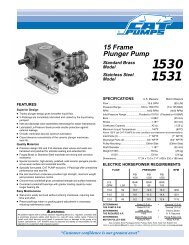
TRIGGER<br />
GUN<br />
WAND<br />
HIGH PRESSURE<br />
HOSE<br />
BURNER EXHAUST<br />
VENT<br />
BURNER<br />
ENGINE FUEL<br />
TANK<br />
COIL DRAIN<br />
PLUG<br />
Figure 1 - Machine Component Layout (<strong>871SS</strong> Shown)<br />
ENGINE<br />
BURNER SWITCH<br />
HIGH PRESSURE<br />
NOZZLES<br />
THERMOSTAT<br />
HOUR<br />
METER<br />
CONTROL<br />
BOX<br />
ANTI-SIPHON<br />
VALVE<br />
Page 4 Hotsy <strong>781SS</strong>, <strong>871SS</strong>, 921SS <strong>97</strong>-<strong>6642</strong> Rev. 10/04<br />
PUMP<br />
BURNER FUEL<br />
TANK<br />
DETERGENT<br />
INJECTOR<br />
DETERGENT<br />
INLET LINE
INTRODUCTION<br />
Thank you for purchasing a Hotsy <strong>Pressure</strong> Washer.<br />
This manual covers the operation and maintenance of<br />
the <strong>781SS</strong>, <strong>871SS</strong> and 921SS washers. All information<br />
in this manual is based on the latest product information<br />
available at the time of printing.<br />
Hotsy, Inc. reserves the right to make changes at any<br />
time without incurring any obligation.<br />
Owner/User Responsibility:<br />
The owner and/or user must have an understanding of<br />
the manufacturer’s operating instructions and warnings<br />
before using this Hotsy pressure washer. Warning information<br />
should be emphasized and understood. If the<br />
operator is not fluent in English, the manufacturer’s instructions<br />
and warnings shall be read to and discussed<br />
with the operator in the operator’s native language by<br />
the purchaser/owner, making sure that the operator<br />
comprehends its contents.<br />
Owner and/or user must study and maintain for future<br />
reference the manufacturers’ instructions.<br />
This manual should be considered a permanent<br />
part of the machine and should remain with it if<br />
machine is resold.<br />
When ordering parts, please specify model and<br />
serial number.<br />
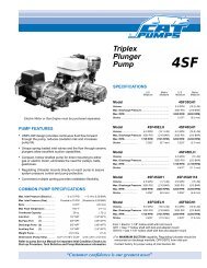
ASSEMBLY<br />
Unpacking<br />
Unpack carefully. Wear safety glasses or goggles while<br />
unpacking, assembling, or operating pressure washer. If<br />
there are missing components or hidden damage,<br />
immediately contact carrier concerning discrepancies.<br />
1. Cut strapping band from pressure washer and pallet.<br />
2. Remove pressure washer from pallet.<br />
Parts Included<br />
• <strong>Pressure</strong> Washer<br />
<strong>Pressure</strong> Hose<br />
Wand<br />
Operating Instructions and Parts Manual<br />
Gasoline Engine Manual<br />
Parts Bag Containing:<br />
■ <strong>Pressure</strong> Nozzles (3 Ea.)<br />
■ Quick Disconnects (2 Ea.)<br />
■ Quick Disconnect Plug<br />
■ Trigger Gun<br />
Tools Required<br />
8" Adjustable Wrench<br />
Teflon Tape<br />
Flat Blade Screwdriver<br />
Hotsy <strong>781SS</strong>, <strong>871SS</strong>, 921SS <strong>97</strong>-<strong>6642</strong> Rev. 10/04<br />
<strong>Pressure</strong> Hose, Trigger Gun and Wand<br />
1. When assembling, use teflon tape on all threaded<br />
plumbing connections to prevent leakage.<br />
2. Install the pressure hose on the pressure washer as<br />
shown in Figure 2.<br />
Figure 2 - <strong>Pressure</strong> Hose Installation to Coil<br />
3. Assemble wand components as shown in Figure 3.<br />
NOTE: The pressure nozzle is not to be installed at<br />
QUICK<br />
DISCONNECT<br />
PRESSURE HOSE<br />
WAND<br />
QUICK DISCONNECT PLUG<br />
TRIGGER GUN<br />
PRESSURE HOSE<br />
RELIEF VALVE<br />
QUICK DISCONNECT<br />
Figure 3 - <strong>Pressure</strong> Hose Installation to Trigger Gun<br />
this time.<br />
4. Make sure all plumbing connections are tight.<br />
Page 5
IMPORTANT SAFETY<br />
INSTRUCTIONS<br />
WARNING: When using this machine basic precautions<br />
should always be followed, including the following:<br />
CAUTION: To reduce the risk of<br />
CAUTION<br />
injury, read operating instructions<br />
carefully before using.<br />
READ OPERATOR’S<br />
MANUAL THOROUGHLY<br />
PRIOR TO USE.<br />
1. Read the owner's manual thoroughly.<br />
Failure to follow instructions<br />
could cause malfunction<br />
and result in death,<br />
serious bodily injury and/or<br />
property damage.<br />
2. Know how to stop the machine and bleed pressures<br />
quickly. Be thoroughly familiar with the controls.<br />
3. Stay alert - watch what you are doing.<br />
4. All installations must comply with local codes. Contact<br />
your electrician, plumber, utility company or<br />
the selling distributor for specific details.<br />
WARNING: Flammable liquids<br />
WARNING<br />
can create fumes which can ignite<br />
causing property damage or<br />
severe injury.<br />
RISK OF EXPLOSION:<br />
DO NOT SPRAY<br />
FLAMMABLE LIQUIDS.<br />
WARNING<br />
KEEP WATER SPRAY<br />
AWAY FROM<br />
ELECTRICAL WIRING.<br />
5. Risk of explosion - do not<br />
spray flammable liquids or operate<br />
in an explosive location.<br />
Operate only where open<br />
flame or torch is permitted.<br />
WARNING: Do not place machine<br />
near flammable objects when<br />
the engine is hot.<br />
WARNING: Keep water spray<br />
away from electrical wiring or fatal<br />
electric shock may result.<br />
Read warning tag on electrical<br />
cord.<br />
WARNING: Spray gun kicks back. Hold with both<br />
hands.<br />
6. Grip cleaning wand securely with both hands before<br />
starting the cleaner. Failure to do this could<br />
result in injury from a whipping wand.<br />
WARNING: Risk of fire. Do not<br />
WARNING<br />
add fuel when the machine is operating.<br />
RISK OF EXPLOSION:<br />
USE CAUTION WHEN<br />
REFUELING.<br />
7. Allow engine to cool for 2 minutes<br />
before refueling. If any<br />
fuel is spilled, make sure area<br />
is dry before testing spark<br />
plug or starting the engine.<br />
(Fire and/or explosion may<br />
occur if this is not done.)<br />
Gasoline engines on mobile or portable equipment shall<br />
be refueled:<br />
a. Outdoors;<br />
b. With the engine on the equipment stopped;<br />
c. With no source of ignition within 10 feet of the<br />
dispensing point;<br />
d. With an allowance made for expansion of the<br />
fuel should the equipment be exposed to a higher<br />
ambient temperature.<br />
In an overfilling situation, additional precautions are<br />
necessary to ensure that the situation is handled in<br />
a safe manner.<br />
WARNING<br />
HIGH PRESSURE<br />
STREAM CAN PIERCE<br />
SKIN AND TISSUES.<br />
WARNING<br />
RISK OF<br />
ASPHYXIATION.<br />
USE THIS PRODUCT<br />
ONLY IN A WELL<br />
VENTILATED AREA.<br />
WARNING: Risk of injection or severe<br />
injury to persons - Keep<br />
clear of nozzle — Do not touch<br />
or direct discharge stream at persons.<br />
This machine is to be used<br />
only by trained operators.<br />
CAUTION: Hot discharge fluid.<br />
Do not touch or direct discharge<br />
stream at persons.<br />
8. High pressure developed by these machines can<br />
cause personal injury or equipment damage. Use<br />
caution when operating. Do not direct discharge<br />
stream at people, or severe injury and/or death may<br />
result.<br />
WARNING: High pressure can<br />
WARNING<br />
cause paint chips or other particles<br />
to become airborne and fly<br />
at high speeds.<br />
USE PROTECTIVE<br />
EYEWEAR WHEN<br />
OPERATING.<br />
9. Eye safety devices and foot<br />
protection must be worn when<br />
using this equipment.<br />
10. Never make adjustments on<br />
machine while in operation.<br />
WARNING: Use only in well ventilated<br />
areas. Failure to observe<br />
this warning could cause a loss<br />
of consciousness or death.<br />
11. Avoid installing in small areas<br />
or near exhaust fans. Exhaust<br />
contains poisonous carbon<br />
monoxide gas; exposure may<br />
cause loss of consciousness<br />
and may lead to death. It also<br />
contains chemicals known, in certain quantities, to<br />
cause cancer, birth defects or other reproductive<br />
harm.<br />
12. Do not operate with the spray gun in the off position<br />
for extensive periods of time as this may cause<br />
damage to the pump.<br />
13. The best insurance against an accident is precaution<br />
and knowledge of the machine.<br />
Page 6 Hotsy <strong>781SS</strong>, <strong>871SS</strong>, 921SS <strong>97</strong>-<strong>6642</strong> Rev. 10/04
14. Hotsy will not be liable for any changes made to<br />
our standard machines, or any components not purchased<br />
from Hotsy.<br />
15. Read engine safety instructions provided.<br />
16. Never run pump dry or leave trigger gun closed longer<br />
than 5 minutes.<br />
17. Inlet water must be from a cold, clean fresh city<br />
water supply.<br />
WARNING: Only use recom-<br />
WARNING<br />
mended fuel. Using other fuels<br />
may result in a serious explosion<br />
causing personal injury, property<br />
damage or loss of life.<br />
18. Use No. 1 or No. 2 heating oil<br />
(ASTM D306) only. NEVER<br />
use gasoline in your fuel oil<br />
tank. Gasoline is more combustible<br />
than fuel oil and could<br />
result in a serious explosion. NEVER use crankcase<br />
or waste oil in your burner assembly. Fuel unit<br />
malfunction could result from contamination.<br />
RISK OF FIRE OR<br />
EXPLOSION: USE<br />
VAPOR FUEL ONLY.<br />
19. Do not confuse gasoline and fuel oil tanks. Keep<br />
proper fuel in proper tank.<br />
20. Protect machine from freezing.<br />
21. Be certain all quick coupler fittings are secured before<br />
using pressure washer.<br />
22. Do not allow acids, caustic or abrasive fluids to<br />
pass through the pump.<br />
23. To reduce the risk of injury, close supervision is necessary<br />
when a product is used near children. Do not<br />
allow children to operate the pressure washer. This<br />
machine must be attended during operation.<br />
24. Do not operate this product when fatigued or under<br />
the influence of alcohol or drugs. Keep operating<br />
area clear of all persons.<br />
25. Protect high pressure hose from vehicle traffic and<br />
sharp objects.<br />
26. Before disconnecting high pressure hose from water<br />
outlet, turn burner off and pull the trigger on the spray<br />
gun allowing water to cool to below 100° F before<br />
stopping machine. Then open the trigger gun to relieve<br />
pressure. Failure to properly cool down or maintain<br />
the heating coil may result in a steam explosion.<br />
27. Do not overreach or stand on unstable support. Keep<br />
good footing and balance at all times.<br />
28. This machine must be attended during operation.<br />
INSTALLATION<br />
Getting Started<br />
IMPORTANT: Proper initial installation of equipment<br />
will assure more satisfactory performance, longer<br />
service life, and lower maintenance cost.<br />
Hotsy <strong>781SS</strong>, <strong>871SS</strong>, 921SS <strong>97</strong>-<strong>6642</strong> Rev. 10/04<br />
IMPORTANT: The use of a backflow preventer on<br />
the water supply hose is recommended and may be<br />
required by local code.<br />
The pressure washer should be run on a level surface and<br />
in a protected area where it is not readily influenced by<br />
outside forces such as strong winds, freezing temperatures,<br />
rain, etc. The pressure washer should be located to assure<br />
easy access for filling of fluids, adjustments and<br />
maintenance. Normal precautions should be taken by the<br />
operator to prevent moisture from reaching the pressure<br />
washer. It is recommended that a partition be made between<br />
the wash area and the pressure washer to prevent direct<br />
spray from the wand from coming in contact with the<br />
pressure washer. Moisture reaching the equipment will<br />
reduce the pressure washer’s service life. All installations<br />
must comply with the local codes covering such installations.<br />
Venting<br />
DANGER: DO NOT run machine indoors or in an<br />
enclosed area, as exhaust fumes may be hazardous<br />
to your health.<br />
DANGER: DO NOT operate machine in areas where<br />
flammable vapors (gasoline, solvents, etc.) may be<br />
present, as this machine may ignite the vapors.<br />
CAUTION: All venting must be in accordance with<br />
applicable federal and state laws, and local ordinances.<br />
Consult local heating contractors.<br />
If the pressure washer is to be used in an enclosed area, a<br />
flue must be installed to vent burner and engine exhaust<br />
to the outside atmosphere. Be sure the flue is the same<br />
size as the burner exhaust vent on the pressure washer.<br />
See Figure 1 for location. Poor draft will cause the pressure<br />
washer to soot and not operate properly. When selecting<br />
the location for installation, beware of poorly ventilated<br />
locations or areas where exhaust fans may cause an<br />
insufficient supply of oxygen. Proper combustion can only<br />
be obtained when there is a sufficient supply of oxygen<br />
available for the amount of fuel being burned. If it is<br />
necessary to install the machine in a poorly ventilated<br />
area, outside fresh air may have to be piped to the burner<br />
and a fan installed to bring sufficient air into the machine.<br />
Locate the pressure washer so that the flue will be as<br />
straight as possible and protrude through the roof at a<br />
proper height and location to provide adequate draft. This<br />
oil fired pressure washer must have a draft regulator<br />
installed in the flue (available from most heating<br />
contractors). A draft regulator will permit proper upward<br />
flow of exhaust flue gases.<br />
In addition, the pressure washer should never be operated<br />
in an enclosed area where high ambient temperatures exist.<br />
High ambient temperatures (above 100o F) can cause engine<br />
oil failure and will greatly reduce the engine’s performance.<br />
Gasoline Engine<br />
The gasoline engine is preset for operation at altitudes<br />
below 3000 feet above sea level. If operated at higher<br />
altitudes, it may be necessary to install a high altitude<br />
main jet in the carburetor. Contact an authorized engine<br />
sales and service center for details.<br />
Page 7
Pre-Operation Check<br />
❑ Pump Oil (SAE 30W non-detergent oil)<br />
❑ Cold Water Supply (3.5 gpm • 5/8" • 20 psi)<br />
❑ Hose, wand, nozzles (nozzle size per serial plate)<br />
❑ Water filter (intact, nonrestrictive)<br />
❑ Engine fuel (unleaded 86 or higher)<br />
❑ Engine oil (SAE 10W40)<br />
❑ Burner fuel (No. 1 or No.2 home heating fuel or diesel)<br />
Oil Burner<br />
Burner Air Adjustment: The oil burner on this machine<br />
is preset for operation at altitudes below 3000 feet. If<br />
operated at higher altitudes, it may be necessary to<br />
adjust the air shutter and air band setting. Adjust the air<br />
shutter for a #1 or #2 smoke spot on the Bacharach<br />
scale.<br />
To adjust, start machine and turn burner ON (refer to<br />
Operation for details). Loosen two locking screws found<br />
in the air shutter openings (refer to Figure 4) and close<br />
air shutter until black smoke appears from burner<br />
exhaust vent. Note air shutter position. Next, slowly<br />
open the air shutter until white smoke just starts to<br />
appear. Turn air shutter halfway back to the black smoke<br />
position previously noted. Tighten locking screws.<br />
AIR SHUTTER LOCKING SCREW<br />
AIR SHUTTER<br />
2<br />
4<br />
6<br />
8<br />
10<br />
AIR SHUTTER<br />
LOCKING SCREW<br />
AIR BAND<br />
Figure 4 - Burner Adjustment<br />
AIR BAND<br />
LOCKING SCREW<br />
If the desired position cannot be obtained using only<br />
the air shutter, lock the air shutter in as close a position<br />
as can be obtained, then repeat the above procedure<br />
on the air band setting.<br />
CAUTION: If white smoke appears from burner<br />
exhaust vent during start-up or operation, discontinue<br />
use and readjust air bands.<br />
NOTE: If a flue is installed, have a professional serviceman<br />
adjust your burner for a #1 or #2 smoke<br />
spot on the Bacharach scale.<br />
OPERATION<br />
Before Starting<br />
1. Read all manuals provided with this pressure washer.<br />
Become familiar with location and function of all<br />
operating and safety controls.<br />
WARNING: Check hoses, fittings, wand, trigger gun<br />
and fuel connections daily for signs of wear, cracks<br />
and looseness, and replace as required.<br />
2. Connect water supply hose to the garden hose connector<br />
located on pump. The water faucet and supply<br />
hose must be capable of providing a minimum of 3.5<br />
gallons per minute (GPM).<br />
3. Fill oil burner fuel tank. Use kerosene, #1 grade home<br />
heating oil, #1 or #2 diesel fuel. DO NOT USE GASO-<br />
LINE, CRANKCASE OIL DRAININGS, OR WASTE<br />
OIL.<br />
WARNING: DO NOT fill engine fuel tank while engine<br />
is running or hot. Let engine cool before refueling<br />
or spontaneous fire may result. Fuel spillage or vapors<br />
could ignite if engine is hot.<br />
4. Fill the engine fuel tank. Do not overfill, fill to the<br />
bottom of filler neck only. Use lead free gasoline<br />
minimum 86 octane. DO NOT use gasoline containing<br />
more than 15% MTBE, 5% methanol or 10%<br />
ethanol. Refer to the provided gasoline engine<br />
manual for additional details.<br />
5. Check pump and engine oil levels.<br />
6. If detergents are to be used, only use detergents<br />
intended for pressure washers. Follow instructions on<br />
the detergent container.<br />
IMPORTANT: Before installing pressure nozzle on<br />
initial start-up, turn on the water supply and allow<br />
water to run from the end of the wand until clear to<br />
prevent the pressure nozzle from clogging.<br />
IMPORTANT: If the pressure washer has not been<br />
used for an extended period of time, remove the pressure<br />
nozzle from the end of the wand and turn on<br />
water supply. Allow water to run from the end of the<br />
wand until clear.<br />
7. Install the proper pressure nozzle for your cleaning<br />
needs on the end of wand, refer to Figure 5.<br />
MANUAL TRIGGER LOCK<br />
PRESSURE<br />
NOZZLE<br />
Figure 5 - Nozzle Installation/Manual Trigger Lock<br />
Page 8 Hotsy <strong>781SS</strong>, <strong>871SS</strong>, 921SS <strong>97</strong>-<strong>6642</strong> Rev. 10/04
IMPORTANT: The trigger gun provided with this pressure<br />
washer is equipped with a manual trigger lock<br />
to prevent accidental operation of the trigger gun.<br />
(Refer to Figure 5.) The manual trigger lock should be<br />
used whenever the trigger gun is not in use.<br />
To Start<br />
DANGER: DO NOT point wand or trigger gun at yourself<br />
or at any person. Bodily injury may result from<br />
water under high pressure.<br />
WARNING: Wear eye, ear, hand, foot and skin protection<br />
at all times while operating pressure washer.<br />
IMPORTANT: The water must be turned on before<br />
starting. Running the pump dry will cause damage<br />
and void warranty.<br />
IMPORTANT: DO NOT allow the machine to run with<br />
trigger of the trigger gun released for more than<br />
10 minutes at any one time or damage to pump may<br />
occur.<br />
1. Turn ON water supply.<br />
2. Hold wand firmly, release trigger of trigger gun.<br />
3. Place engine ON/OFF switch in the ON position.<br />
4. Open fuel shutoff valve (if so equipped). Move choke<br />
lever to FULL CHOKE position, (choke may not be<br />
needed on warm engine). Move throttle lever to HALF<br />
THROTTLE position.<br />
5. Pull the rope starter slowly until resistance is felt, then<br />
pull briskly. Do not allow the rope starter to snap back<br />
against the engine. Return it gently to prevent damage<br />
to the starter.<br />
6. When the engine starts, move choke lever until<br />
engine runs smoothly. When engine warms, move<br />
choke lever to NO CHOKE position. Move throttle<br />
lever to FULL THROTTLE position.<br />
IMPORTANT: To allow for proper burner operation, the<br />
throttle control must be kept in the full throttle position<br />
during operation.<br />
NOTE: If engine fails to start, refer to Troubleshooting<br />
Guide in this manual.<br />
7. Squeeze trigger of trigger gun and allow air to purge<br />
from system.<br />
8. If HOT water is desired, adjust the thermostat to the<br />
proper temperature and turn burner switch ON. The<br />
burner will light immediately with a small puff of<br />
smoke. You may need to initially adjust your burner<br />
for peak performance. See Oil Burner section under<br />
Installation. If smoke continues, contact Customer<br />
Service at 1-303-792-5200. When the trigger of the<br />
trigger gun is released or when the thermostat temperature<br />
setting is reached, the burner will automatically<br />
turn off.<br />
To Clean<br />
DANGER: DO NOT place hands or fingers in front of<br />
high pressure spray. Bodily injury may result.<br />
Hotsy <strong>781SS</strong>, <strong>871SS</strong>, 921SS <strong>97</strong>-<strong>6642</strong> Rev. 10/04<br />
The detergent injector valve operates by reducing the<br />
volume of water, thus a vacuum is achieved and<br />
detergent is drawn into the system. DO NOT reduce the<br />
water inlet flow so the pump cavitates due to water<br />
starvation. Operating a pump with insufficient water will<br />
damage the pump seals.<br />
1. Insert detergent inlet line into container of mixed<br />
detergent.<br />
2. Completely open detergent control knob located on<br />
the side of the detergent injector valve. Refer to<br />
WATER ADJUSTMENT KNOB<br />
WATER<br />
INCREASE<br />
DETERGENT<br />
OFF<br />
Figure 6 - Detergent Injector Valve<br />
WATER<br />
DECREASE<br />
DETERGENT<br />
ON<br />
DETERGENT CONTROL KNOB<br />
Figure 6.<br />
3. Start the detergent suction by rotating the water<br />
adjustment knob of the detergent injector valve.<br />
Refer to Figure 6. Turning the knob counterclockwise<br />
will pull detergent into the system. The flow<br />
may be observed through the clear detergent line.<br />
Secure the knob position with the knurled nut.<br />
4. The side detergent control knob can now be adjusted<br />
to meter the desired amount of detergent.<br />
5. Wash from the bottom to the top, using side to side<br />
motions. This washes away heavy dirt and allows<br />
the detergent to soak as you work toward the top.<br />
6. Do not wash at a 90 o angle to the work (straight at<br />
it). This will allow water to splash back at you and<br />
reduces your cleaning power. Wash at a 30° to 60°<br />
angle to the work. This will allow the water to splash<br />
away from you and the water will wash the dirt away<br />
faster and easier.<br />
7. Use the width of the spray pattern to wash in a wide<br />
path. Overlap spray paths for complete coverage<br />
washing from side to side, using slow, steady<br />
motions.<br />
8. The nozzle should be 12" to 24" from work, closer<br />
for tough areas. Be careful on painted or delicate<br />
surfaces, the pressure may damage surface if nozzle<br />
is too close.<br />
9. Small parts should be washed in a basket so the<br />
Page 9
pressure does not push them away. Larger, lightweight<br />
parts should be clamped down so the pressure<br />
does not push them away.<br />
10. Turn the side detergent control knob clockwise (CW)<br />
for detergent decrease. Wait for detergent to clear.<br />
Always rinse with cold water after using detergent.<br />
Rinse from the top to the bottom to prevent detergent<br />
from dripping onto a rinsed area. For the best results,<br />
contact your Hotsy dealer to help you select the best<br />
detergent for your application.<br />
To Stop<br />
1. If detergents were used, draw clear water through the<br />
detergent inlet line to purge detergent. Failure to do<br />
so may clog detergent injector valve.<br />
2. If burner was used, turn OFF burner switch and<br />
allow pump to run cold water through coil for several<br />
minutes.<br />
3. Move throttle lever to idle position.<br />
4. Turn engine ON/OFF switch to the OFF position.<br />
5. Close fuel shutoff valve (if so equipped).<br />
6. Turn water supply OFF.<br />
7. Squeeze trigger of trigger gun to relieve system<br />
pressure.<br />
STORAGE<br />
DANGER: DO NOT store flammable liquids (gasoline,<br />
diesel fuel, solvents, etc.) near pressure washer,<br />
or in non-ventilated areas.<br />
Protect from freezing by storing in a heated area, or by<br />
flushing the system with antifreeze (use an automotive<br />
engine antifreeze or windshield washer solvent to<br />
antifreeze). To flush the system with antifreeze, the<br />
following steps are to be followed:<br />
1. Connect the water supply hose to the garden<br />
hose connector located on the pump. Turn on water<br />
supply.<br />
2. Place the detergent inlet line into a container of<br />
antifreeze.<br />
3. Hold wand firmly, release trigger of trigger gun.<br />
4. Start engine. Place throttle lever in Full Throttle<br />
position.<br />
5. Squeeze trigger of trigger gun and allow water to<br />
flow from the end of the wand. Watch for antifreeze to<br />
be drawn through the detergent inlet line. Allow the<br />
antifreeze to be drawn into the system for 5 to 10<br />
seconds.<br />
6. Release the trigger of the trigger gun and stop<br />
engine.<br />
7. Turn off water supply and disconnect water supply<br />
hose from the pump.<br />
8. Attach a short length of hose (approximately 3 feet<br />
long) to the garden hose connector located on the<br />
pump. Install a funnel in the other end of the hose<br />
Figure 7 - Winterizing<br />
FUNNEL<br />
GARDEN<br />
HOSE<br />
CONNECTOR<br />
as shown in Figure 7.<br />
9. Hold wand firmly, release the trigger of the trigger<br />
gun.<br />
10. Start engine. Place throttle lever in the idle position.<br />
11. Squeeze trigger on trigger gun.<br />
12. Slowly pour antifreeze into the funnel. Continue to<br />
add antifreeze until antifreeze flows from the end of<br />
the wand.<br />
13. Squeeze and release the trigger of the trigger gun<br />
several times to antifreeze the unloader system.<br />
14. Release the trigger of the trigger gun. Stop engine.<br />
15. Squeeze the trigger of the trigger gun to relieve system<br />
pressure.<br />
For added protection, after antifreezing, disconnect the<br />
pressure hose from the machine and remove the coil<br />
drain plug (refer to Figure 1 for location.) After coil has<br />
drained, replace pressure hose and coil drain plug. If<br />
the pressure washer is not to be used for an extended<br />
length of time, it is recommended that the system be<br />
flushed with antifreeze for rust protection. Refer to the<br />
Gasoline Engine Manual for engine storage<br />
information.<br />
Page 10 Hotsy <strong>781SS</strong>, <strong>871SS</strong>, 921SS <strong>97</strong>-<strong>6642</strong> Rev. 10/04
MAINTENANCE<br />
WARNING: Unauthorized machine modification or<br />
use of non-approved replacement parts may cause<br />
personal injury and/or property damage and will<br />
void the manufacturer warranty.<br />
Pump<br />
Lubrication: To lubricate pump, use 30W non-detergent<br />
oil for pump crankcase. Crankcase must be filled to<br />
center of red dot on oil gauge found on the side of the<br />
pump, refer to Figure 8. During the break-in-period, make<br />
sure the oil is changed after the first 40 hours of<br />
operation. After that, replace oil every 3 months or 500<br />
hours of operation, whichever comes first.<br />
OIL FILL/DIPSTICK<br />
OIL DRAIN<br />
PLUG OIL GAUGE<br />
Figure 8 - Pump Lubrication<br />
Proper Pump Care:<br />
DO NOT pump acids.<br />
DO NOT allow pump to run dry.<br />
Winterize if storing in freezing temperatures, refer<br />
to Storage for details.<br />
Use a water softener on the water system if known<br />
to be high in mineral content.<br />
Use only high quality detergents and follow manufacturer's<br />
mix recommendations.<br />
Flush the system with clear water immediately<br />
after using detergent solutions.<br />
Clean filter screen on detergent inlet line<br />
periodically.<br />
Flush the pressure washer system with antifreeze<br />
if storing for an extended period of time, refer to<br />
Storage for details.<br />
Hotsy <strong>781SS</strong>, <strong>871SS</strong>, 921SS <strong>97</strong>-<strong>6642</strong> Rev. 10/04<br />
Gasoline Engine<br />
Refer to the provided Gasoline Engine Manual for<br />
recommended maintenance.<br />
Relief Valve<br />
WARNING: The relief valve on this pressure washer<br />
has been factory set and sealed and is a field nonadjustable<br />
part. Tampering with the factory setting<br />
may cause personal injury and/or property damage,<br />
and will void the manufacturer warranty. For replacement<br />
parts refer to Figure 18.<br />
Unloader Valve<br />
WARNING: The unloader valve on this pressure<br />
washer has been factory set and sealed and is a field<br />
nonadjustable part. Tampering with the factory setting<br />
may cause personal injury and/or property damage,<br />
and will void the manufacturer warranty. For<br />
replacement refer to Figures 12-14.<br />
Burner Fuel Filter<br />
Drain any water which has accumulated in fuel filter<br />
and clean or replace filter element as needed. Refer to<br />
Figure 10.<br />
Heating Coil<br />
Coil Descaling: In hard water areas, scale buildup within<br />
the heating coil will occur. Scale deposits will decrease<br />
the water temperature rise and may eventually clog the<br />
heating coil. Contact your local service center when<br />
descaling is needed.<br />
Coil Desooting: Poor grades of fuel oil or inadequate<br />
combustion air will cause heavy soot buildup on the<br />
outside surface of the heating coil. These deposits will<br />
insulate the coil. This will restrict the air flow through the<br />
coil, further aggravating the soot buildup. Contact your<br />
local service center when desooting is needed.<br />
Hour Meter<br />
This hour meter will monitor the total hours of operation<br />
of the pressure washer to signal when routine<br />
maintenance is required.<br />
Page 11
TROUBLESHOOTING GUIDE<br />
SYMPTOM POSSIBLE CAUSES CORRECTIVE ACTION<br />
Gas engine will not run. Out of gas. Replenish supply. Use only recommended<br />
fuels. Refer to Before Starting<br />
under Operation.<br />
uel valve closed (if so equipped). Open valve.<br />
<strong>Pressure</strong> washer runs<br />
but won't spray.<br />
Low spray pressure at<br />
pressure nozzle.<br />
Loose spark plug wire. Reconnect.<br />
Choke or throttle set incorrectly. Refer to To Start under Operation.<br />
Engine ON/O switch in O<br />
position.<br />
Place engine ON/O switch in ON<br />
position.<br />
Low engine oil level. Replenish supply. Engine will not start<br />
or run if oil is low (on engines equipped<br />
with low oil protection).<br />
Refer to provided gasoline engine manual for additional troubleshooting.<br />
Trigger of trigger gun released. Squeeze trigger.<br />
Water supply not turned on. Open water supply valve.<br />
Clogged pressure nozzle. Clean pressure nozzle opening.<br />
Inadequate water supply. ully open faucet. Check for kinked or<br />
damaged hose. Use 5/8 inch minimum<br />
hose. Check for debris clogging inlet<br />
screen.<br />
Partially clogged or damaged<br />
pressure nozzle.<br />
Air being drawn through detergent<br />
inlet line.<br />
Detergent injector valve not set<br />
correctly.<br />
Uneven spray pattern. Partially clogged or damaged<br />
pressure nozzle.<br />
<strong>Pressure</strong> washer will<br />
not produce hot water.<br />
Clean or replace.<br />
Refill detergent container. Ensure that<br />
pick-up screen is fully immersed.<br />
Refer to To Clean for settings.<br />
Clean or replace.<br />
Burner switch in O position. Place switch in ON position.<br />
Inadequate fuel supply. Refill fuel tank. Use only recommended<br />
fuels. Refer to Before Starting<br />
under Operation.<br />
Inadequate water supply. ully open faucet. Check for kinked or<br />
damaged hose. Use 5/8 inch minimum<br />
hose. Check for debris clogging inlet<br />
screen.<br />
Trigger of trigger gun released. Squeeze trigger. Water must be spraying<br />
for burner to light.<br />
Page 12 Hotsy <strong>781SS</strong>, <strong>871SS</strong>, 921SS <strong>97</strong>-<strong>6642</strong> Rev. 10/04
When ordering from your dealer, please provide the following:<br />
Model Number: <strong>781SS</strong>, <strong>871SS</strong>, 921SS<br />
Machine Serial Number: ________________________________<br />
Component Part Number: ______________________________<br />
Description: __________________________________________<br />
Hotsy <strong>781SS</strong>, <strong>871SS</strong>, 921SS <strong>97</strong>-<strong>6642</strong> Rev. 10/04<br />
TROUBLESHOOTING GUIDE<br />
SYMPTOM POSSIBLE CAUSES CORRECTIVE ACTION<br />
<strong>Pressure</strong> washer will not<br />
produce hot water.<br />
...continued<br />
Poor or no detergent<br />
flow.<br />
Thermostat set too low. Adjust thermostat to desired temperature.<br />
Blown fuse. Replace. use is located in Control<br />
Box.<br />
Engine is running too slow. Move throttle lever to full throttle<br />
position.<br />
Inadequate detergent supply. Refill detergent container. Ensure that<br />
pick-up screen is fully immersed. Open<br />
detergent valve.<br />
Detergent screen or hose clogged. Clean. Always start with a clean detergent<br />
container.<br />
Detergent injector valve not set<br />
correctly.<br />
Clogged detergent injector check<br />
valve.<br />
Poor cleaning. Improper detergent concentration or<br />
mixing.<br />
Refer to To Clean for settings.<br />
Clean check valve at detergent injector<br />
inlet.<br />
Mix detergent per manufacturer's<br />
instructions. Ensure that powdered<br />
detergents are fully dissolved.<br />
Wrong detergent for the application. Select appropriate detergent.<br />
Rinsing with hot water. A final rinse with cold water will reduce<br />
water spotting.<br />
IMPORTANT<br />
If the pressure washer demonstrates other symptoms or the corrective actions<br />
listed do not correct the problem, contact the local authorized Hotsy Service<br />
Center. The Hotsy Service Center can be identified by visiting www.hotsy.com<br />
or by calling 1-800-525-1<strong>97</strong>6.<br />
Page 13
20<br />
21<br />
22<br />
FOR<br />
DETAIL SEE<br />
BURNER<br />
ILLUS.<br />
6<br />
5<br />
Figure 9 - Exploded View Left Side<br />
12<br />
14, 55<br />
25<br />
44<br />
19<br />
2<br />
18<br />
17<br />
RECTIFIER<br />
(REVERSED<br />
VIEW)<br />
26<br />
Page 14 Hotsy <strong>781SS</strong>, <strong>871SS</strong>, 921SS <strong>97</strong>-<strong>6642</strong> Rev. 10/04<br />
1<br />
27<br />
15<br />
6<br />
16<br />
53<br />
5 10<br />
23<br />
24<br />
FOR<br />
DETAIL<br />
SEE COIL<br />
OUTLET<br />
ILLUS.<br />
7<br />
5<br />
9<br />
6<br />
13<br />
FOR<br />
DETAIL SEE<br />
CONTROL<br />
BOX<br />
ILLUS.<br />
11<br />
8
51<br />
Hotsy <strong>781SS</strong>, <strong>871SS</strong>, 921SS <strong>97</strong>-<strong>6642</strong> Rev. 10/04<br />
54<br />
50<br />
52<br />
31<br />
48<br />
49<br />
28<br />
32<br />
29<br />
47<br />
30<br />
4<br />
31<br />
6<br />
45<br />
32<br />
32<br />
31<br />
46<br />
31<br />
FOR<br />
DETAIL SEE<br />
PUMP ASSY<br />
ILLUS.<br />
42<br />
34<br />
33<br />
33<br />
35<br />
41<br />
32<br />
43<br />
39<br />
36,37<br />
38<br />
40<br />
3<br />
Page 15
Ref. No. Part No. Description Qty.<br />
1 318226 Chassis, Welded Assy 1<br />
375575 Chassis, Weldment (921SS) 1<br />
2 780460 Washer, 5/16" x 1-1/4",<br />
Fender, SAE 3<br />
3 952724 Tank, Fuel, 6-Gallon 1<br />
952733 Tank, Fuel, 8 Gal Hotsy (921SS) 1<br />
4 707116 Hose, 1/4", Fuel Line, Green (22") i<br />
5 703155 Nut, 5/16", SMAEC, NC 15<br />
6 780452 Washer, 5/16", Flat, SAE 12<br />
7 859815 Grommet, Rubber, Nozzle Holder 3<br />
8 646113 Label, Detergent Metering 1<br />
9 785096 Mount, Rubber Vibration, 40 Duro 2<br />
10 784446 Mount, Rubber, Vibration, 30 Duro 2<br />
11 834416 Label, Instructions 1<br />
12 860273 Regulator, Voltage, 15 Volt 1<br />
13 357054 TGB, RD 0.375 x .125W x 30 1<br />
14 735323 Screw, 10/32" x 3/4" BH SOC CS 4<br />
15 268006 Insulation, Cerfelt 16" x 50" 1<br />
16 226222 Coil, 16" 1<br />
17 698247 Nipple, 1/2" Hex, Steel 1<br />
18 375449 Coil, Tank SS, Weldment 1<br />
19 824115 Clip, Retaining, U-Type 4<br />
20 213044 Top Hat, Weld Assy,<br />
16" Hotsy Coil 1<br />
21 268004 Insulation, Cerfelt, 16 OD x 8.3 ID 1<br />
22 860102 Ring, Insulation Retainer,<br />
16" Top Hat 1<br />
23 829<strong>97</strong>9 Label, Plate Aluminum 2<br />
24 10-07993 Label, Warnings 1<br />
25 859806 Grommet, 2-1/8" x 2-7/8" x 7/16"<br />
Rubber 1<br />
26 815329 Bushing, 1" Snap 1<br />
27 616000 Bushing, Snap, 5/8" 1<br />
28 698200 Nipple, 1/4" x 2" x 1/2", Brass 1<br />
29 615279 Bushing, 3/8" x 1/4", Galv. 1<br />
30 851080 Filter, Fuel Hotsy, 3/8" Female 1<br />
31 698020 Hose Barb, 1/4" Barb x 1/4" ML Pipe 3<br />
32 823988 Clamp, Hose, UNI .46-.54 ST 4<br />
33 867368 Hose, 1/4", Push-On, Fuel Line i<br />
34 780456 Washer, 5/8", Flat, SAE 8<br />
35 983013 Wheel & Tire, 6.5"<br />
Steel Rim, 12.5" Tire 4<br />
Ref. No. Part No. Description Qty.<br />
36 817322 Cap, 5/8" Axle Hub, Black 4<br />
37 848616 Nut, .61 ID, Push, Flat 4<br />
38 817312 Cap, w/Fuel Gauge 1<br />
39 661277 Standpipe 1<br />
40 2-0027 Elbow, 3/8" 1<br />
41 799490 Swivel, 1/4" JIC Fem, Push-On 1<br />
42 815230 Bushing, Rubber, Nitrile 2<br />
43 2-10491 Plug, 1/4"JIC 1<br />
44 213191 Insulation 1<br />
45 615433 Bolt, 5/16" - 24 x 3/4" NF HH 4<br />
46 860282 Reducer, M14 to 1/4" F 1<br />
47 646226 Label, Hot/Caliente<br />
w/Arrows Warning 1<br />
48 661278 Engine, 7 HP Robin (<strong>871SS</strong>) 1<br />
661280 Engine, 6HP Robin (<strong>781SS</strong>) 1<br />
5-0005 Engine, Robin 9HP (921SS) 1<br />
49 615939 Screw, 5/16" x 1-1/2" Whiz 4<br />
50 4-02037824 Hose, 3/8" x 24", 2 Wire,<br />
<strong>Pressure</strong> Loop 1<br />
51 801102 Nipple, 3/8" Hex, Steel 1<br />
52 715744 Plug, 3/8", Sq. Head, Galv. 1<br />
53 926598 Rivet, 1/8" x 1/4", POP, AL 8<br />
54 954812 Tee, 3/8" NPT, 2500 WP, Brass 1<br />
55 799484 Nut, 10/32" Keps 4<br />
▲ 444461 Label, Caution, Gasoline, White 1<br />
▲ 646026 Label, Warning, Carbon Monoxide 1<br />
▲ 834153 Label, Fuel Type 1<br />
▲ 834154 Label, Caution Winterize 1<br />
▲ 834159 Label, Use Hotsy Detergent 1<br />
▲ 646095 Label, Troubleshooting 1<br />
▲ 213191 Insulation Pancake, 18" 1<br />
▲ 753187 Key, 3/16" x 3/16" x 2" SST 1<br />
▲ 890874 Tag, Oil Burner 1<br />
▲ 735321 Screw, 4 mm x 6 mm, Pan Head 1<br />
▲ 11-3101 Tab, Gas Engine 1<br />
▲ 11-3100 Warning, Unloader 1<br />
▲ Not Shown<br />
❉ Order Amount Needed In Feet<br />
Page 16 Hotsy <strong>781SS</strong>, <strong>871SS</strong>, 921SS <strong>97</strong>-<strong>6642</strong> Rev. 10/04
1-1/8"<br />
9<br />
Figure 10 - Burner Assembly<br />
8<br />
5/32"<br />
AIR CONE<br />
ELECTRODE SETTINGS<br />
1/4"<br />
5/32"<br />
Ref. No. Part No. Description Qty.<br />
1 616027 Burner 1<br />
2 698023 Nipple 3/8" x 1/4" Hose 1<br />
3 ✪ 851080 Fuel Filter 1<br />
4 615279 Reducer Bushing 3/8" x 1/4" 1<br />
5 698200 Pipe Nipple 1/4" x 2-1/2" 1<br />
6 661257 Street Elbow 1/4" 1<br />
7 698019 Nipple 1/8" x 1/4" Hose 1<br />
Hotsy <strong>781SS</strong>, <strong>871SS</strong>, 921SS <strong>97</strong>-<strong>6642</strong> Rev. 10/04<br />
2<br />
3<br />
6<br />
4<br />
7<br />
5<br />
10<br />
Ref. No. Part No. Description Qty.<br />
8 900650 Nozzle, 1.50, 90° 1<br />
9 661413 Electrodes 1<br />
10 830492 Fuel Pump 1<br />
11 723369 Solenoid 1<br />
12 676894 Fuel Line 1<br />
▲ 783813 Motor 1<br />
▲ 630730 Coupling 1<br />
▲ 676640 Blower Fan 1<br />
■ Standard hardware item available locally.<br />
▲ Not Shown<br />
Replacement Parts<br />
1<br />
11<br />
12<br />
✪ 875490 Filter Element 1<br />
Page 17
14<br />
Figure 11 - Control Box Assembly<br />
Ref. No. Part No. Description Qty.<br />
1 95-0710983516 Box, Front 1<br />
2 11-0511 Label, Control Box 1<br />
3 785118 Hour Meter, 12-28 V DC 1<br />
4 875465 Switch, Rocker, 15A/12V 1<br />
5 835150 Knob, Thermostat 1<br />
6 735321 Screw, 4mm x 6mm, Pan Head 2<br />
7 915390 Plate, Thermostat Cover 1<br />
8 955930 Thermostat 1<br />
9 707147 Capacitor 1<br />
13<br />
Ref. No. Part No. Description Qty.<br />
10 612937 Bolt, 1/4" x 3/4" 4<br />
11 630649 Channel 2<br />
12 703127 Locknut, 1/2" 3<br />
13 615414 Box, Back 1<br />
14 703185 Nut, 1/4" 4<br />
15 6-051561 Strain Relief 3<br />
▲ 676638 Fuse, ATC 30 Amp 1<br />
▲ 707146 Holder, Fuse 1<br />
▲ 829620 Plug 1<br />
16 358026 Clamp 1<br />
17 612945 Bolt, 1/4-20 x 1/2" 1<br />
18 703106 Nut, 1/4" 1<br />
19 2-011681 Cap, Capacitor, 1.37 x 1.50 x<br />
.060 BLK, W/o Hole 1<br />
20 860140 Relay 1<br />
▲ Not Shown<br />
Page 18 Hotsy <strong>781SS</strong>, <strong>871SS</strong>, 921SS <strong>97</strong>-<strong>6642</strong> Rev. 10/04<br />
12<br />
15 2<br />
11<br />
10<br />
20<br />
1<br />
8<br />
19<br />
9, 16, 17, 18<br />
3<br />
4<br />
7<br />
6<br />
5
Figure 12 - Pump Assembly (<strong>871SS</strong> Shown)<br />
Ref. No. Part No. Description Qty.<br />
1 830148 Pump, Hawk, HHS335BR, Bulk Pkg 1<br />
2 921464 Unloader, HM SS Unset 1<br />
3 898141 Nipple, 3/8" x 2"L, Brass 1<br />
4 961534 Hose, 1/4" x 1/2", Braided<br />
Vinyl 4 ft.<br />
5 935159 Strainer, Chemical,<br />
with 1/4" Brass Barb 1<br />
6 823989 Clamp, Hose, UNI .40-.48 ST 1<br />
Hotsy <strong>781SS</strong>, <strong>871SS</strong>, 921SS <strong>97</strong>-<strong>6642</strong> Rev. 10/04<br />
1<br />
2<br />
11<br />
14<br />
10<br />
3<br />
9<br />
4<br />
8<br />
7<br />
Ref. No. Part No. Description Qty.<br />
7 801126 Swivel, 3/8" MP x 3/4" GHF<br />
w/Strainer 1<br />
8 873596 Injector, Adjustable, Inlet 1<br />
9 661356 Elbow, 1/2" JIC x 3/8" Fem, 90° 1<br />
10 829663 Plug, 3/8" Gas Tap 1<br />
11 875651 Switch, <strong>Pressure</strong>, Black 1<br />
12 ▲ 921421 Pump Protector 1<br />
13 921395 Valve, Anti-Siphon 1<br />
14 799515 Nipple, 1/2" JIC x 3/8" Pipe 1<br />
15 ▲ 875575 Spring, .95 x .055 x .6 1<br />
▲ Not Shown<br />
6<br />
5<br />
13<br />
Page 19
15<br />
12<br />
11<br />
Figure 13 - Pump, Exploded View (<strong>781SS</strong> Shown)<br />
10<br />
3 4<br />
Ref. No. Part No. Description Qty/Pump<br />
1 830160 Pump, Comet, 2527G 1<br />
2 661356 Elbow, 1/2" JIC x 3/8", 90° 1<br />
3 801126 Swivel, GHF 1<br />
4 661361 Elbow, 3/8", 45° Street 1<br />
5 873596 Injector Adjustable 1<br />
6 600071 Nipple, 3/8" Hex 1<br />
7 875651 Switch, <strong>Pressure</strong> 1<br />
8 722787 Elbow, 1/8" MNPT x 1/4" FNPT 1<br />
9 921421 Pump Protector 1<br />
10 823988 Clamp, Hose, UNI .46 - .54 1<br />
11 961534 Hose, 1/4" x 1/2" Braided 4 ft.<br />
12 935159 Strainer 1<br />
13 715736 Plug, 1/8 Sq. 1<br />
14 600260 Adapter 3/8 NPT x 1/4 NPT 1<br />
15 921395 Valve, Anti-Siphon 1<br />
5<br />
2<br />
9<br />
7<br />
14<br />
Page 20 Hotsy <strong>781SS</strong>, <strong>871SS</strong>, 921SS <strong>97</strong>-<strong>6642</strong> Rev. 10/04<br />
6<br />
13<br />
8<br />
1
3<br />
Figure 14 - Pump, Exploded View (921SS Shown)<br />
1<br />
Ref. No. Part No. Description Qty/Pump<br />
1 5-1260 Pump, Hotsy HS3040 1<br />
2 5-3029 Unloader, PA 8GPM@3650 PSI, VB55<br />
EZ/47 Series 1<br />
3 921422 Pump, Protector, 1/2" PTP 1<br />
4 722774 Nipple, 1/2" x 3/8", Pipe 1<br />
5 873596 Injector, Adjustable, Inlet 1<br />
6 961534 Hose, 1/4" x 1/2" Braided<br />
Vinyl 4 ft.<br />
7 935159 Strainer, Chemical w/1/4" Brass<br />
Barb 1<br />
8 823989 Clamp, Hose, UNI .40-.48ST 1<br />
Hotsy <strong>781SS</strong>, <strong>871SS</strong>, 921SS <strong>97</strong>-<strong>6642</strong> Rev. 10/04<br />
15<br />
14<br />
2<br />
13<br />
6<br />
4<br />
12<br />
5<br />
9<br />
8<br />
Ref. No. Part No. Description Qty/Pump<br />
9 661361 Elbow, 3/8" Steel, Street, 45° 2-00575 1<br />
10 801126 Swivel, 3/8" MP x 3/4" GHF<br />
w/Strainer 2-10943 1<br />
11 921395 Valve, Anti-Siphon, Watts 8BI 2-30062 1<br />
12 661357 Elbow, 1/2" JIC, 3/8", 90° 2-0053 1<br />
13 830584 Plug, 1/8" Countersunk 2-1044 1<br />
14 644802 Elbow, 3/8" Street 2-0031 1<br />
15 875651 Switch, <strong>Pressure</strong> 6-02165<br />
1<br />
7<br />
10<br />
11<br />
Page 21
Figure 15 - Pump, Exploded View (<strong>781SS</strong> Shown)<br />
Ref. No. Part No. Description Qty/Pump<br />
1 89-3202001800 Cap 1/8"" 1<br />
2 89-3609015600 Screw M8 x 55 4<br />
3 89-1220004500 Valve Kit 6<br />
4 89-1210004900 O-Ring 1.78 x 12.42 6<br />
5 89-3009012900 Valve Seat 6<br />
6 89-3604002800 Suc./Del. Valve 6<br />
7 89-1802019200 Spring 6<br />
8 89-1205003300 Valve Cage 6<br />
9 89-0601027300 Spacer 2<br />
10 89-1210015100 O-Ring 1.78 x 17.17 6<br />
11 89-3202023600 Plug 6<br />
12 89-1215027100 Reg. Val Kit for AX 270 PSI 1<br />
13 89-1817005300 Knob 1<br />
14 89-3622003000 Stop Adjustable Nut M4 x 4 1<br />
15 89-1227002200 Nut 1<br />
16 89-1802018200 Spring 1<br />
17 89-0204004600 Adjustable Knob 1<br />
18 89-0009020700 Seat 1<br />
19 89-2409007700 Piston Rod 1<br />
20 89-1210040600 O-Ring 1<br />
21 89-0009020600 Ring 1<br />
Ref. No. Part No. Description Qty/Pump<br />
22 89-0204004500 Housing 1<br />
23 89-1210040700 O-Ring 1<br />
24 89-1210040500 O-Ring 1<br />
25 89-0009020500 Ring 1<br />
26 89-1210040400 O-Ring 1<br />
27 89-0009020400 Ring 1<br />
28 89-3002050800 Housing with Ball 1<br />
29 89-3009012200 Seat 1<br />
30 89-1210040300 O-Ring 1<br />
31 89-3009001300 Valve Seat 1<br />
32 89-1210035600 O-Ring 1.78 x 25.12 3<br />
33 89-1241005000 Piston Seal Ø14 3<br />
34 89-0019010300 Sealing Ring 3<br />
35 89-3201001800 Oil Level Plug 1<br />
36 89-1802015300 Spring 3<br />
37 89-2409008900 Piston 3<br />
38 89-0009022100 Ring 3<br />
39 89-0009022000 Ring Ø14 3<br />
41 89-3200007100 Plug G3/8 1<br />
42 89-3002052200 Support 1<br />
43 89-0019003400 Sealing Ring 40 x 55 x 7 1<br />
Page 22 Hotsy <strong>781SS</strong>, <strong>871SS</strong>, 921SS <strong>97</strong>-<strong>6642</strong> Rev. 10/04
<strong>781SS</strong> Pump Exploded View Parts List Continued<br />
Ref. No. Part No. Description Qty/Pump<br />
44 89-1210042900 O-Ring 1<br />
45 89-0001039500 Eccentric Shaft 3/4"" 1<br />
46 89-0438007600 Ball Bearing 40 x 80 x 18mm 1<br />
47 89-0001041700 Eccentric Shaft 8"" 1<br />
48 89-0436001600 Axial Bearing 1<br />
49 89-2816002500 Thrust Bearing 1<br />
50 89-3609000500 Screw M8 x 20 1<br />
51 89-0403013500 Pump Crankcase 1<br />
52 89-3609000500 Screw M8 x 20 4<br />
53 89-3410029800 Injector Body 3/8 NPT 1<br />
54 89-1210004900 O-Ring 1.78 x 12.42 1<br />
55 89-1210004000 O-Ring 1.78 x 15.6 1<br />
56 89-3410030300 Injector Body Kit 3/8 NPT 1<br />
57 89-180201<strong>97</strong>00 Spring 1<br />
58 89-2409008600 Check Valve 1<br />
Hotsy <strong>781SS</strong>, <strong>871SS</strong>, 921SS <strong>97</strong>-<strong>6642</strong> Rev. 10/04<br />
Ref. No. Part No. Description Qty/Pump<br />
59 89-121003<strong>97</strong>00 O-Ring 1<br />
60 89-2409009100 Check Valve Kit 1<br />
61 89-0009021900 Ring 3<br />
62 89-0009023000 Ring 3<br />
63 89-1241005600 Piston Seal 2700 PSI 3<br />
64 89-3200001700 Plug 1/8 x 8 1<br />
65 89-3200000700 Plug 3/8 Gas OT58 1<br />
66 89-2803043500 Injector Kit 1<br />
67 89-2803042500 Hose Barb Fitting 1<br />
68 89-2812006700 O-Ring 1<br />
69 89-3003002600 Ball 1<br />
70 89-1802018000 Spring 1<br />
71 89-3218029900 Pump Valve Chamber 1<br />
72 89-3200001700 Plug 1/8 x 8 1<br />
77 89-2800008100 Garden Hose Swivel 1<br />
Page 23
4<br />
Figure 16 - Pump, Exploded View (<strong>871SS</strong> Shown)<br />
Ref. No. Part No. Description Qty/Pump<br />
1 8781<strong>97</strong> Allen Screw 6<br />
2 735313 Crankcase Cover Allen Screw 5<br />
3 858431 Sight Glass, 3/8" 1<br />
4 827324 Crankcase Cover 1<br />
5 855889 Crankcase Cover Gasket 1<br />
6 630685 Crankshaft 1<br />
7 617639 Ball, Bearing 1<br />
8 630684 Crankshaft Seal 1<br />
9 600127 Mounting Range 1<br />
2<br />
1<br />
5<br />
Page 24 Hotsy <strong>781SS</strong>, <strong>871SS</strong>, 921SS <strong>97</strong>-<strong>6642</strong> Rev. 10/04<br />
3<br />
Ref. No. Part No. Description Qty/Pump<br />
10 780561 Washer 4<br />
11 876152 Mounting Flange Screw 4<br />
Replacement Parts<br />
753701 Seal Packing Kit (15mm) 1<br />
753037 Complete Seal Packing Kit (15mm) 3<br />
753039 Complete Valve Assembly Kit 6<br />
877655 Plunger Seal Kit 1<br />
753040 Ceramic Sleeve Kit (15mm) 3
Figure 17- Pump, Exploded View (HS3040G, HS3540G, HS4040G, HS5030G)<br />
ITEM PART NO. DESCRIPTION QTY ITEM PART NO. DESCRIPTION QTY ITEM PART NO. DESCRIPTION QTY<br />
1 70-020225 Crankcase 1<br />
2 70-060201 Plunger Guide 3<br />
3* 70-000103 Plunger Oil Seal 3<br />
4* 70-060107 O-Ring Ø1.78 x 31.47 3<br />
5* 70-000220 "V" Seal , 15mm 6<br />
6* 70-120120 <strong>Pressure</strong> Ring, 15mm 3<br />
7* 70-030027 Support Ring 15mm 6<br />
8* 70-030020 Intermed. Ring 15mm 3<br />
9 70-160120 Brass Plug, 1/2" 1<br />
10 70-060307 Copper Washer 1/2" 1<br />
11 70-160216 Manifold Housing 1<br />
12* 70-060119 O-Ring Ø2.62 x 17.13 6<br />
13* 70-360470 Valve Assembly 6<br />
14* 70-060165 O-Ring Ø2.62 x 20.29 6<br />
15 70-160130 Valve Plug 6<br />
16 70-180103 Manifold Stud Bolt 8<br />
17 70-140001 Washer 8<br />
18 70-060306 Copper Washer 3/8" 1<br />
19 70-160117 Brass Plug 3/8" 2<br />
20** 70-150318 Valve Seat 6<br />
21** 70-120200 Valve Plate 6<br />
Hotsy <strong>781SS</strong>, <strong>871SS</strong>, 921SS <strong>97</strong>-<strong>6642</strong> Rev. 10/04<br />
22** 70-090030 Valve Spring 6<br />
23** 70-060405 Valve Cage 6<br />
24 70-180112 Hexagonal Screw 9<br />
25 70-140002 Washer 4<br />
26 70-050056 Closed Bearing Housing 1<br />
27 70-060163 O-Ring Ø 1.78 x 60.05 2<br />
28 70-150003 Snap Ring 1<br />
29 70-021310 Double Row Ball Bearing1<br />
30 70-000491 Crankshaft (3040G) 1<br />
70-000492 Crankshaft (3540G) 1<br />
70-000493 Crankshaft (4040G) 1<br />
70-000494 Crankshaft (5030G)<br />
31 70-180302 Set Screw 1<br />
32 70-160006 Oil Dip Stick 1<br />
33 70-020010 Needle Roller Bearing 1<br />
34 70-050055 Engine Flange 1<br />
35 70-140304 Spring Washer 4<br />
36 70-180128 Flange Screw 4<br />
37 70-180220 Engine Screw, 5/16" 4<br />
38 70-140051 Washer 4<br />
39 70-140103 Spring Washer 4<br />
REPAIRKITNUMBER70-260824 70-260825 70-260823 70-260007 70-260027<br />
KIT<br />
DESCRIPTION<br />
ITEMNUMBERS INCLUDED<br />
NUMBE<br />
R OF<br />
CYLIN<br />
DERS<br />
KIT<br />
WILL<br />
SERVICE<br />
Plunger<br />
Seal<br />
15mm<br />
4,<br />
5,<br />
7<br />
Complete<br />
SealPacking15mmPlunger15mm Complete<br />
Valve<br />
3,<br />
4,<br />
5,<br />
6,<br />
7,<br />
8<br />
44,<br />
45,<br />
46,<br />
47,<br />
48<br />
TORQUE<br />
SPECS<br />
Item # Ft.<br />
-lbs<br />
1575 1630 2418 349 4513 5111 40 70-180221 Engine Screw 3/8" 4<br />
41 70-140052 Washer 4<br />
42 70-140053 Spring Washer 4<br />
43 70-000109 Crankshaft Seal 1<br />
44* 70-030211 Plunger Nut 3<br />
45* 70-120025 Plunger, 15mm 3<br />
46* 70-140027 Copper Spacer 3<br />
47* 70-060130 O-Ring Ø1.78x5.28 3<br />
48* 70-000913 Teflon Ring 3<br />
49 70-000302 Plunger Rod 3<br />
50 70-150001 Snap Ring 6<br />
51 70-150201 Connecting Rod Pin 3<br />
52 70-010001 Connecting Rod 3<br />
53 70-140102 Spring Washer 6<br />
54 70-180105 Connecting Rod Screw 6<br />
55 70-060009 Cover Gasket 1<br />
56 70-020350 Crankcase Cover 1<br />
57 70-060302 Gasket, G3/8 1<br />
58 70-070001 Sight Glass, G3/8 1<br />
* Part available in kit (See below)<br />
** Part available in kit ONLY (See below)<br />
Plunger<br />
Oil<br />
Seals<br />
12, 13,<br />
14<br />
3<br />
1 3 3 1 1<br />
Page 25
Figure 18 - Pump, Exploded View<br />
Page 26 Hotsy <strong>781SS</strong>, <strong>871SS</strong>, 921SS <strong>97</strong>-<strong>6642</strong> Rev. 10/04
Figure 19 - Coil Outlet Assembly<br />
Ref. No. Part No. Description Qty.<br />
1 698247 Hex Nipple 1/2" x 2" 1<br />
2 875555 Relief Valve Seat 1<br />
3 799501 Elbow 1/4" x 3/8" Hose 1<br />
4 780565 Copper Washer 2<br />
5 915630 Plug 3/8" 2<br />
Hotsy <strong>781SS</strong>, <strong>871SS</strong>, 921SS <strong>97</strong>-<strong>6642</strong> Rev. 10/04<br />
1<br />
9<br />
4,5<br />
6<br />
4,5<br />
Ref. No. Part No. Description Qty.<br />
6 783845 Relief Valve Manifold 1<br />
7 ■ Screw 4mm x 6 mm 1<br />
8 644802 Street Elbow 3/8" 1<br />
9 640100 Relief Valve Cartridge 1<br />
■ Standard hardware item available locally.<br />
2<br />
7<br />
8<br />
3<br />
Page 27
Figure 20 - Trigger Gun/Wand Assembly<br />
Ref. No. Part No. Description Qty.<br />
1 867207 Hose, 3/8" x 50', 1 Wire,<br />
Tuff-Skin 1<br />
2 860447 Gun, Shutoff 1<br />
3 915786 Nipple, 1/4" x 1/4" NPT ST Male 1<br />
4 826169 Coupler, 1/4" Female, Brass 2<br />
5 936647 Wand, SGL STR, Insulated, 48" 1<br />
6 799091 Nozzle, SACQMEG, 0003.5,<br />
Red 1<br />
799092 Nozzle, SACQMEG, 1503.5,<br />
Yellow 1<br />
799093 Nozzle, SACQMEG, 4003.5,<br />
White 1<br />
3<br />
1<br />
2<br />
4<br />
5<br />
Page 28 Hotsy <strong>781SS</strong>, <strong>871SS</strong>, 921SS <strong>97</strong>-<strong>6642</strong> Rev. 10/04<br />
4<br />
6
Figure 21 - Wiring Diagram (<strong>871SS</strong> Shown)<br />
Hotsy <strong>781SS</strong>, <strong>871SS</strong>, 921SS <strong>97</strong>-<strong>6642</strong> Rev. 10/04<br />
Page 29
<strong>97</strong>-<strong>6642</strong> • Rev. 10/04<br />
WARRANTY<br />
HOTSY LIMITED WARRANTY:<br />
Hotsy products are warranted by the Hotsy Corporation (Hotsy) to be free of defects in material and<br />
workmanship under normal use, for a period of ONE YEAR from the date of the original purchase.<br />
Items that fail due to normal wear such as o-rings hoses, seals, quick couplers, nozzles, gunjets, etc. or<br />
damage resulting from neglect, abuse, tampering, or modification are not covered under this warranty.<br />
Hotsy will at its option repair or replace any part covered by this warranty which is defective under<br />
normal use for one year at no charge for parts or labor. All defects must be verified by an authorized<br />
Hotsy service location. This warranty is not transferable.<br />
EXCEPTIONS TO THE ONE YEAR WARRANTY FOR PARTS ONLY ARE:<br />
Hotsy Pumps: SEVEN YEAR Warranty (LIFETIME Brass Manifold Warranty-<br />
Even Against Freezing)<br />
General Pumps: FIVE YEAR Warranty<br />
Heating Coils: FOUR YEAR Warranty<br />
LIMITATION OF LIABILITY:<br />
To the extent allowable under applicable law, Hotsy liability for consequential and incidental damages<br />
is expressly disclaimed. Hotsy liability in all events is limited to, and shall not exceed, the purchase<br />
price paid for the equipment. Hotsy liability is limited to repair or replacement of defective parts only, at<br />
the option of the Hotsy Corporation.<br />
WARRANTY DISCLAIMER:<br />
Hotsy has made a diligent effort to illustrate and describe the product in this literature accurately;<br />
however, such illustrations and descriptions are for the sole purpose of identification, and do not<br />
express or imply a warranty that the product is merchantable or fits a particular purpose, or that the<br />
product will necessarily conform to the illustrations or descriptions.<br />
PRODUCT SUITABILITY:<br />
Many states and localities have codes and regulations governing sales, construction, installation, and/<br />
or use of products for certain purposes, which may vary from those in neighboring areas. While<br />
attempts to assure that its products comply with such codes, it cannot guarantee compliance and<br />
cannot be responsible for how the product is installed or used. Before purchase and use of a product,<br />
please review the product application, and national and local codes and regulations, and be sure that<br />
the product, installation, and use will comply with them.<br />
PROMPT DISPOSITION:<br />
Hotsy will make a good faith effort for prompt correction or other adjustments with respect to any<br />
product which proves to be defective within limited warranty. For any product believed to be defective<br />
within limited warranty, contact dealer from whom product was purchased. Dealer will give additional<br />
directions. If unable to resolve satisfactorily, write to Hotsy at address below, giving dealer's name,<br />
address, date of purchase, model, serial number, and describing the nature of the defect. If product<br />
was damaged in transit to you, file claim with freight carrier.<br />
The Hotsy Corporation<br />
www.hotsy.com<br />
1-800-525-1<strong>97</strong>6