Betriebsanleitung (Original) SK 41 ... - ASO Safety
Betriebsanleitung (Original) SK 41 ... - ASO Safety
Betriebsanleitung (Original) SK 41 ... - ASO Safety

Create successful ePaper yourself
Turn your PDF publications into a flip-book with our unique Google optimized e-Paper software.
7.2 Electrical connection<br />
• Connect suppl�� voltage 230 V AC (115 V AC) to terminals A1 A2 or 24 V AC/DC to terminals B1<br />
(+) B2 (-).<br />
• Connect the sensor to terminals X1 X2.<br />
• Connect the control circuit that is to be monitored to terminals 13 24. In the case o� redundant<br />
routing o� the switching contacts, the �actor��-mounted jumper between terminals 14 23 is to be<br />
removed.<br />
• For manual reset, bridge terminals S11 S12 (�actor�� setting: autom. reset, S11 S12 not bridged)<br />
and connect the reset push-button to terminals Z1 Z2.<br />
Upon success�ul commissioning, sa�et�� output 13 24 is activated (rela�� contact "closed"). Actuation<br />
o� the sensor causes rela�� contact 13 24 to open and the auxiliar�� rela�� to switch according to the<br />
given switching unit version. This is indicated with the aid o� the ��ellow Aux LED.<br />
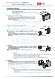
7.3 Connection of multiple sensors<br />
<strong>ASO</strong> sensors must not be connected in parallel.<br />
One or more sensors (e.g. sa�et�� contact edges) can be connected to the sensor input X1 X2. For<br />
this purpose, the individual sensors are connected in series.<br />
An unused input can be bridged with an 8.2 k kΩ resistor.<br />
Up to five sensors may be connected in series, whereby the total cable length must not exceed<br />
25 m.<br />
Be�ore connecting the sensors that are connected in series, the resistance value o� the arrangement<br />
be measured. It must not exceed 8.3k kΩ .<br />
X1<br />
X2<br />
2<br />
7.4 Functional test<br />
Signalgeber 1 Signalgeber 2 Signalgeber „n“<br />
The plant / machine must be tested �or proper �unction a�ter all o� the electrical connections have<br />
been established and the suppl�� voltage has been turned on.<br />
• Actuate the sensors in sequence.<br />
• Check the switching units �or proper reaction.<br />
2<br />
Figure 1: Wiring of multiple sensors; in this example: safety contact edge<br />
The sa�et�� s��stem must be pro�essionall�� inspected at appropriate intervals.<br />
The inspection must be documented in such a wa�� as to be comprehensible at all times.<br />
The requirements o� the plant/machine manu�acturer are to be taken into account and �ollowed.<br />
2<br />
2<br />
English<br />
17