Membrane Based Triethylene Glycol Separation and Recovery from ...
Membrane Based Triethylene Glycol Separation and Recovery from ...
Membrane Based Triethylene Glycol Separation and Recovery from ...

You also want an ePaper? Increase the reach of your titles
YUMPU automatically turns print PDFs into web optimized ePapers that Google loves.
<strong>Membrane</strong> <strong>Based</strong> <strong>Triethylene</strong> <strong>Glycol</strong> <strong>Separation</strong> <strong>and</strong> <strong>Recovery</strong><br />
<strong>from</strong> Gas <strong>Separation</strong> Plant Wastewater<br />
by<br />
Pimchanok Khachonbun<br />
A thesis submitted in partial fulfillment of the requirements for the<br />
degree of Master of Engineering in<br />
Environment Engineering <strong>and</strong> Management<br />
Examination Committee: Prof. Chettiyappan Visvanathan (Chairperson)<br />
Prof. Ajit P. Annachhatre<br />
Dr. Romchat Rattanaoudom (External Expert)<br />
Nationality: Thai<br />
Previous Degree: Bachelor of Engineering in Environmental<br />
Engineering<br />
Suranaree University of Technology, Thail<strong>and</strong><br />
Scholarship Donor: Royal Thai Government – AIT Fellowship<br />
Asian Institute of Technology<br />
School of Environment, Resources <strong>and</strong> Development<br />
Thail<strong>and</strong><br />
May 2013<br />
i
Acknowledgements<br />
I would like to express my heartfelt thanks <strong>and</strong> profound gratitude to my advisor, Prof. C.<br />
Visvanathan, who has supported me throughout my thesis with his excellent guidance,<br />
encouragement <strong>and</strong> valuable suggestions. Without his supervision <strong>and</strong> constructive<br />
assistance, this study would not have been in its present shape.<br />
Special appreciation is also extended to Prof. Ajit P. Annachhatre <strong>and</strong> Dr. R.<br />
Rattanaoudom as the thesis committee members, who provided valuable comments,<br />
support, suggestions <strong>and</strong> assistances toward the usefulness of the study.<br />
I would like to gratefully acknowledge to Royal Thai Government (RTG) for scholarships<br />
for the Master study in AIT. Moreover, my deep gratitude goes to Petroleum Authority of<br />
Thail<strong>and</strong> (PTT), for providing technical support for my research.<br />
I am thankful to Prof. C. Visvanathan’s research group for their support. Especially my<br />
thanks go to Mr. P. Jacob <strong>and</strong> Mr. T. Rathnayake for their technical support <strong>and</strong><br />
encouragement to complete the research successfully.<br />
In addition, my deep great gratitude also is extended to all my dear teachers, faculty<br />
members <strong>and</strong> all staffs <strong>and</strong> technicians of EEM for their help, technical <strong>and</strong> moral support<br />
<strong>and</strong> cooperation, which assisted me to complete this thesis.<br />
I would like to express my deep thanks to my colleagues, Ms. Phontida, Mr. Supawat, Mr.<br />
Phanwatt, Mr. Kiattisak, Mr. Duc, Mr. Ahmad, Mr. Siripong, Mr. Lalith, Ms. Kamala <strong>and</strong><br />
Ms. Tasawan for their generous support in technically as well as humanly during the entire<br />
period of my study.<br />
Finally, my achievement would never be possible unless there is hearty support <strong>from</strong> my<br />
family. The deepest <strong>and</strong> sincere gratitude goes to my beloved parents, my younger sister<br />
for their endless love, encouragement <strong>and</strong> underst<strong>and</strong>ing throughout the entire period of<br />
my study.<br />
ii
Abstract<br />
<strong>Triethylene</strong> glycol (TEG) is absorption, involves the use of a liquid desiccant to remove<br />
water content <strong>from</strong> the gas. This study investigated membrane filtration, pervaporation<br />
process <strong>and</strong> design pre-treatment process to treat real wastewater <strong>from</strong> gas separation<br />
plants. In membrane filtration experiment, four types of membrane (NF-TS40, NF-TS80,<br />
RO-ACM5 <strong>and</strong> RO-NTR759HR) were tested with synthetic wastewater. NF-TS80 is the<br />
best of nanofiltration membrane to recover TEG, with a 70% TEG recovery. Moreover,<br />
RO-ACM5 was the most effective membrane of reverses osmosis membrane, with a 90%<br />
TEG recovery which presented at low concentration applied (0.1%, 5% <strong>and</strong> 10% of TEG).<br />
In case of permeate flux, the low permeate flux (0.01-0.16 L/m 2 .h) presented at high<br />
concentration applied (20% <strong>and</strong> 30% of TEG) that was resulted <strong>from</strong> the effect of<br />
concentration polarization <strong>and</strong> membrane fouling.<br />
Pervaporation process was conducted with 0.1, 5 <strong>and</strong> 10% of TEG concentrations in<br />
synthetic wastewater with temperature variation of 30, 40 <strong>and</strong> 70°C of each concentration.<br />
In case of permeate flux, the high permeate flux 6.81 kg/m 2 .h presented at low<br />
concentration (0.1% of TEG) <strong>and</strong> used high temperature (70°C). While the permeate flux<br />
at a concentration of 10% was found with 0.58 kg/m 2 .h at 40°C. Also, the separation factor<br />
was 698 for 10% TEG at 40°C. The flux <strong>and</strong> the separation factors obtained indicate that<br />
pervaporation process with NaA Zeolite membrane is not attractive <strong>and</strong> the system does<br />
not performed well at lower concentration of solutes.<br />
In pre-treatment experiment, testing with real wastewater using RO-ACM5 <strong>and</strong> NF-TS80<br />
membranes was necessary. However, the wastewater first needs be pretreated to protect<br />
membrane <strong>from</strong> fouling by suspended solids <strong>and</strong> oil/grease by used microfiltration (MF)<br />
<strong>and</strong> ultrafiltration (UF) membrane, respectively. Pre-treatment process coupled with<br />
nanofiltration membrane (TS80) showed higher TEG removal than synthetic wastewater<br />
experiments at 0.1% TEG concentration by approximately 73%. While reverse osmosis<br />
membrane (ACM5) showed slightly higher removal for TEG than synthetic wastewater<br />
experiments with 0.5% TEG concentration also by approximately 95%. In case of 8.3%<br />
TEG concentration, nanofiltration (TS80) <strong>and</strong> reverse osmosis (ACM5) membrane showed<br />
relatively equal to the value of synthetic wastewater experiments by approximately 47.15%<br />
<strong>and</strong> 77.56%, respectively. Therefore, the pre-treatment process should be applied before<br />
using membrane filtration with NF <strong>and</strong> RO membrane which are proposed for industrial<br />
applications due to its high removal efficiency, high permeate flux with low TEG<br />
concentrations.<br />
iii
Table of Contents<br />
Chapter Title Page<br />
Title Page<br />
Acknowledgements<br />
Abstract<br />
Table of Contents iv<br />
List of Tables vi<br />
List of Figures vii<br />
List of Abbreviations viii<br />
1 Introduction 1<br />
1.1 Background of the Study<br />
1.2 Objectives of the study<br />
1.3 Scope of the Study<br />
2 Literature Review 4<br />
3<br />
4<br />
2.1 <strong>Triethylene</strong> <strong>Glycol</strong> Characteristics<br />
2.1.1 General properties<br />
2.1.2 Uses of TEG (<strong>Triethylene</strong> glycol)<br />
2.1.3 Distribution in environment<br />
2.1.4 Toxic effects<br />
2.2 Gas <strong>Separation</strong> Plants (GSPs)<br />
2.2.1 Characteristics of TEG in wastewater <strong>from</strong> gas<br />
separation plant<br />
2.3 Treatment Process<br />
2.4 <strong>Membrane</strong> Filtration<br />
2.4.1 <strong>Membrane</strong> applications<br />
2.4.2 Introduction to membrane process<br />
2.4.3 Type of filtration<br />
2.4.4 Operational parameters<br />
2.4.5 Factors affecting membrane filtration<br />
2.4.6 Potential membrane filtration (NF/RO)<br />
2.4.7 Pervaporation technology<br />
Methodology<br />
3.1 Phase I: High Pressure <strong>Membrane</strong> Filtration<br />
3.1.1 Materials<br />
3.1.2 <strong>Membrane</strong> tests unit<br />
3.2 Phase II: <strong>Membrane</strong> of Pervaporation<br />
3.2.1 Materials<br />
3.2.2 <strong>Membrane</strong> tests unit<br />
3.3 Phase III: Design Pre-Treatment Process to Treat<br />
TEG wastewater<br />
3.3.1 Materials<br />
3.4 Indicative Methods for TEG<br />
3.4.1 TEG analysis by gas chromatograph (GC)<br />
Results <strong>and</strong> Discussions<br />
iv<br />
i<br />
ii<br />
iii<br />
1<br />
2<br />
3<br />
4<br />
4<br />
5<br />
5<br />
6<br />
9<br />
9<br />
11<br />
12<br />
12<br />
13<br />
15<br />
16<br />
17<br />
18<br />
19<br />
27<br />
28<br />
28<br />
28<br />
31<br />
31<br />
32<br />
34<br />
34<br />
35<br />
35<br />
38
5<br />
4.1 Phase I: High Pressure <strong>Membrane</strong> Filtration<br />
4.1.1 <strong>Membrane</strong> properties<br />
4.1.2 Permeate flux<br />
4.1.3 Rejection<br />
4.2 Phase II: Pervaporation Process<br />
4.2.1 Permeate flux<br />
4.2.2 <strong>Separation</strong> factor<br />
4.2.3 Rejection<br />
4.3 Phase III: Design Pre-Treatment Process for Treat<br />
TEG Wastewater<br />
4.3.1 <strong>Membrane</strong> properties<br />
4.3.2 Efficiency of TEG wastewater before <strong>and</strong> after<br />
pre-treatment process<br />
4.3.3 Permeate flux of TEG in real wastewater<br />
4.3.4 Rejection of TEG in real wastewater<br />
4.3.5 Real wastewater characteristics after<br />
NF <strong>and</strong> RO membrane treatment<br />
Conclusions <strong>and</strong> Recommendations<br />
5.1 Conclusions<br />
5.2 Recommendations for Further Study<br />
References<br />
Appendix A<br />
Appendix B<br />
Appendix C<br />
Appendix D<br />
Appendix E<br />
Appendix F<br />
v<br />
38<br />
38<br />
39<br />
42<br />
43<br />
43<br />
44<br />
45<br />
46<br />
46<br />
47<br />
49<br />
51<br />
54<br />
56<br />
56<br />
57<br />
60<br />
63<br />
66<br />
70<br />
72<br />
75<br />
77
List of Table<br />
Table Title Page<br />
2.1 Physical <strong>and</strong> Chemical Properties of <strong>Triethylene</strong> <strong>Glycol</strong> 4<br />
2.2 The Number of Facilities of <strong>Glycol</strong>s was Used <strong>and</strong> The Number of<br />
Employees Exposed<br />
6<br />
2.3 Surface Water Quality Guidelines for DEG <strong>and</strong> TEG<br />
6<br />
2.4 The Primary Method of Prevention <strong>and</strong> Medical Care of Human 8<br />
2.5 The Composition of Natural Gas<br />
9<br />
2.6 Total Production Capacity of PTT’s Gas <strong>Separation</strong> Plant<br />
10<br />
2.7 Sources of TEG Wastewater Treatment Plant<br />
11<br />
2.8 Discharged Effluent Characteristics of Gas <strong>Separation</strong> Plants<br />
12<br />
2.9 Detail Explanation of Different <strong>Membrane</strong> Processes<br />
16<br />
2.10 Comparison of Rejection Efficiency of Constituents between NF<br />
<strong>and</strong> RO<br />
19<br />
2.11 Summary of Pervaporation<br />
20<br />
2.12 Overview of Chosen <strong>Membrane</strong> <strong>Separation</strong> Processes<br />
21<br />
2.13 Types of <strong>Membrane</strong> for Pervaporation<br />
22<br />
2.14 Comparison of Pervaporation Modules<br />
24<br />
2.15 Selective <strong>and</strong> Transport Properties of Different Types of<br />
Pervaporation <strong>Membrane</strong>s<br />
25<br />
2.16 Permeate Flux <strong>and</strong> <strong>Separation</strong> Factor of Ethanol/Water Mixture 26<br />
2.17 Comparison of Advantages <strong>and</strong> Disadvantages of Pervaporation 26<br />
3.1 List of NF <strong>Membrane</strong>s <strong>and</strong> Its Properties<br />
28<br />
3.2 List of RO <strong>Membrane</strong>s <strong>and</strong> Its Properties<br />
28<br />
3.3 List of Pervaporation <strong>Membrane</strong>s <strong>and</strong> Its Properties<br />
31<br />
3.4 List of MF <strong>Membrane</strong>s <strong>and</strong> Its Properties<br />
34<br />
3.5 List of UF <strong>Membrane</strong>s <strong>and</strong> Its Properties<br />
35<br />
4.1 <strong>Membrane</strong> Characteristics<br />
38<br />
4.2 Wastewater Characteristics of Real Wastewater <strong>from</strong><br />
<strong>Separation</strong> Plants<br />
Gas 47<br />
4.3 Wastewater Characteristics of Real Wastewater After MF<br />
<strong>Membrane</strong>s Pre-treatment<br />
47<br />
4.4 Wastewater Characteristics of Real Wastewater After UF 49<br />
<strong>Membrane</strong>s Pre-treatment<br />
4.5 Wastewater Characteristics of Real Wastewater After NF 54<br />
4.6<br />
<strong>Membrane</strong>s Pre-treatment<br />
Wastewater Characteristics of Real Wastewater After RO<br />
<strong>Membrane</strong>s Pre-treatment<br />
54<br />
vi
List of Figure<br />
Figure Title Page<br />
2.1 Structures of <strong>Triethylene</strong> <strong>Glycol</strong> (TEG) 4<br />
2.2 Major uses of TEG 5<br />
2.3 Source of TEG wastewater in Gas <strong>Separation</strong> Plant of PTT<br />
(Thail<strong>and</strong>)<br />
10<br />
2.4 Wastewater treatment plants<br />
12<br />
2.5 Demonstrates main characteristics of each membrane types<br />
15<br />
2.6 <strong>Membrane</strong> fouling<br />
17<br />
2.7 Schematic drawing of the pervaporation process with a downstream<br />
vacuum or an inert carrier-gas<br />
19<br />
2.8 Hollow fiber modules<br />
23<br />
2.9 Plate-<strong>and</strong>-frame modules<br />
24<br />
2.10 Spiral wound module<br />
24<br />
2.11 Tubular modules<br />
24<br />
3.1 Experimental plans of study<br />
27<br />
3.2 Flow diagram of membrane experimental set up<br />
29<br />
3.3 Flowchart of membrane filtration experiment<br />
30<br />
3.4 Flowchart of pervaporation membrane experiment<br />
32<br />
3.5 Flow diagram of pervaporation experimental set up<br />
33<br />
4.1 Permeate fluxes of membrane filtrations<br />
40<br />
4.2 Normalized flux of direct filtration at different compound<br />
concentrations<br />
41<br />
4.3 <strong>Membrane</strong> Fouling<br />
42<br />
4.4 Removal efficiency of synthetic wastewater thought membrane<br />
filtration<br />
42<br />
4.5 Permeate fluxes of pervaporation process<br />
44<br />
4.6 <strong>Separation</strong> factor of pervaporation process<br />
44<br />
4.7 Removal efficiency of synthetic wastewater thought pervaporation<br />
process<br />
45<br />
4.8 Design pre-treatment processes to treat TEG wastewater<br />
48<br />
4.9 Permeate fluxes of membrane filtrations with real TEG wastewater 51<br />
4.10 Removal efficiency of real 0.5 <strong>and</strong> 8.3% of TEG wastewater<br />
53<br />
vii
List of Abbreviations<br />
bw Brood War<br />
CAS Chemical Abstracts Service<br />
Da Dalton<br />
DEG Diethylene glycol<br />
EG Ethylene glycol<br />
ESP Ethane <strong>Separation</strong> Plant<br />
GC Gas Chromatography<br />
GSPs Gas <strong>Separation</strong> Plants<br />
KD Kilodalton<br />
kPa Kilopascal<br />
LD Lethal Dose<br />
LD50 Median Lethal Dose<br />
MBR <strong>Membrane</strong> bioreactor<br />
MF Microfiltration<br />
MMSCFD Million St<strong>and</strong>ard Cubic Feet per Day<br />
MSDS Material Safety Data Sheet<br />
NF Nanofiltration<br />
nm Nanometer<br />
PC Personnel computer<br />
ppm Parts per Million<br />
PTT Petroleum Authority of Thail<strong>and</strong><br />
PV Pervaporation<br />
R Compound Rejection<br />
RO Reverse Osmosis<br />
TEG <strong>Triethylene</strong> glycol<br />
TREG Tetraethylene glycol<br />
UF Ultrafiltration<br />
U.S.EPA United States Environmental Protection Agency<br />
wt Net Weight<br />
μm Micrometer<br />
viii
1.1 Background of the Study<br />
Chapter 1<br />
Introduction<br />
One of the best glycol frequently used in dehydration of natural gas is TEG (<strong>Triethylene</strong><br />
glycol). TEG is a colorless, odorless <strong>and</strong> viscous liquid with molecular formula C6H14O4.<br />
Advantages of using TEG are ease of regeneration <strong>and</strong> operation, minimal losses of drying<br />
agent during operation, high affinity for water, chemical stability, high hygroscopicity <strong>and</strong><br />
low vapor pressure at the contact temperature.<br />
In term of toxicity <strong>and</strong> bioaccumulation, TEG is listed as slightly toxic in acute rating <strong>from</strong><br />
U.S.EPA. (2003) <strong>and</strong> low bioconcentration <strong>and</strong> biomagnification. For human, when<br />
considering exposure route of TEG on experiment conditions <strong>and</strong> works with this material<br />
by inhalation, ingestion, skin <strong>and</strong> eyes contact, it has been identified as hazardous <strong>and</strong> for<br />
potential acute <strong>and</strong> chronic health effects. Robertson et al. (1947) exposed rats to TEG in<br />
their drinking water at 3,000 mg/kg bw/day for 13 months. No effects on mortality, body<br />
weight, blood <strong>and</strong> urine composition, <strong>and</strong> gross <strong>and</strong> microscopic appearance of the major<br />
organs was reported. Furthermore, Bossert et al. (1992) exposed mice to drinking water<br />
containing TEG for 14 weeks. No effects were seen at 3,300 mg/kg bw/day, but increased<br />
liver weight was observed at 6,800 mg/kg bw/day.<br />
Apart <strong>from</strong> environmental contamination, their harmful effects on animal <strong>and</strong> human have<br />
also been revealed in many studies. Regarding to animal studies, the effect on rats exposed<br />
to the test material via a whole-body inhalation protocol <strong>and</strong> also receiving the chemical<br />
via the oral <strong>and</strong> dermal routes appears to be low, with reported oral LD50 has value 17,000<br />
mg/kg (MSDS, 2010). Moreover, this study has been repeated using a nose-only exposure<br />
for 6 hours a day for 9 consecutive days. In this inhalation toxicity study, mean exposure<br />
concentrations of 102, 517, or 1,036 mg/m 3 (approximately 0.1, 0.5, 1.0 mg/L/day)<br />
triethylene glycol produced no treatment-related toxicities at any dose tested (McRae,<br />
1998).<br />
In the present, natural gas is one of the most important fuels in our life <strong>and</strong> one of the<br />
principle sources of energy for day-to-day needs <strong>and</strong> activities. It is an important factor for<br />
the development of countries that have strong economy because it is a source of energy for<br />
household, industrial <strong>and</strong> commercial use, as well as to generate electricity. Most natural<br />
gas producers use TEG to remove water in the dehydration process. When TEG is placed<br />
into contact with natural gas it strips the water out of the gas. Thus, TEG is one of the<br />
major components of the wastewater originates <strong>from</strong> a Gas <strong>Separation</strong> Plants (GSPs).<br />
Therefore it is absolutely essential to recover <strong>and</strong> reuse TEG, back in the production<br />
process <strong>and</strong> more reduces wastewater volume in GSPs.<br />
Nowadays, membrane technologies are becoming more frequently used for separation of<br />
wide varying mixtures in the petrochemical related industries <strong>and</strong> can complete<br />
successfully with traditional. <strong>Membrane</strong> technology is widely used in wastewater treatment<br />
processes recently, due to its high performance. Microfiltration (MF), ultrafiltration (UF),<br />
nanofiltration (NF) <strong>and</strong> reverse osmosis (RO) are successfully used to produce high quality<br />
water. Orecki et al. (2006) found that almost use membrane filtration for separation of EG<br />
(ethylene glycol) <strong>from</strong> wastewater by nanofiltration. These studies were conducted using<br />
1
the two membrane module configurations-spiral wound (equipped with membranes:<br />
NF270-2540) <strong>and</strong> NF90-2540) <strong>and</strong> tubular (equipped with membranes AFC 30) for<br />
separation of EG.<br />
Wastewater in petrochemical industry is currently treated by activated sludge process with<br />
pretreatment of oil/water separation (Ravanchi et al., 2009). Tightening effluent<br />
regulations <strong>and</strong> increasing need for reuse of treated water have generated interest in the<br />
treatment of petrochemical wastewater with the advanced membrane bio-reactor (MBR)<br />
process.<br />
Pervaporation (PV) is a membrane process used to separate liquid mixtures. In the<br />
dehydration application, water is removed <strong>from</strong> its mixtures with organic components by<br />
selective permeation through a dense hydrophilic membrane. The most relevant application<br />
of PV is the separation of liquid azeotropes <strong>and</strong> close boiling point solvent-water mixtures.<br />
Nik et al. (2005) found that inorganic membranes <strong>and</strong> particular zeolite membranes are<br />
usually used for the dehydration of organic solvent by pervaporation (PV). In this study on<br />
the pervaporation dehydration of EG/water mixtures using commercial nanoporous NaA<br />
zeolite membranes.<br />
A non-porous membrane separates the liquid feed <strong>from</strong> a downstream compartment to<br />
which vacuum is applied. On the feed side, water is preferentially absorbed on the<br />
membrane. On the permeate side, the water molecules are desorbed <strong>and</strong> removed, due to<br />
the application of vacuum. The sorption of water on the hydrophilic membrane creates a<br />
water concentration gradient, resulting in a diffusive flux across the membrane. Owing to<br />
the vacuum applied at the permeate side of the membrane, permeate is in the vapors state,<br />
so a phase change occurs <strong>from</strong> liquid on the feed side to vapor on the permeate side.<br />
Therefore, when looking at membranes to enhance performance, there is often a trade-off<br />
between separation factor <strong>and</strong> total flux.<br />
1.2 Objectives of the Study<br />
This study aims to develop alternative treatment method for separation <strong>and</strong> recovery of<br />
concentrated TEG <strong>from</strong> wastewater in Gas <strong>Separation</strong> Plants before they are discharged.<br />
The specific objectives of this study are:<br />
1) To investigate efficiency of nanofiltration, reverse osmosis <strong>and</strong> pervaporation<br />
for TEG separation <strong>and</strong> recovery;<br />
2) To develop pre-treatment processes to treat real wastewater generated <strong>from</strong><br />
dehydration unit in Gas <strong>Separation</strong> Plant Wastewater (GSPs).<br />
1.3 Scope of the Study<br />
To accomplish the above objectives, scope of study was set as follows:<br />
1) The study was comprised of 3 phases, <strong>and</strong> their scopes are:<br />
Phase I: High pressure membrane filtration study was conducted in benchscale<br />
with various membrane types (NF/RO) <strong>and</strong> varying compound<br />
concentration.<br />
2
Phase II: membrane of pervaporation study was conducted in bench-scale<br />
with various membrane types <strong>and</strong> varying compound concentration.<br />
Phase III: Design the pre-treatment process to organics <strong>and</strong> inorganics<br />
compound separation in real wastewater <strong>from</strong> GSPs before pass through<br />
membrane filtration (NF/RO) process.<br />
2) The wastewater applied in this study of phase I <strong>and</strong> II was synthesized <strong>from</strong><br />
MiliQ® water, TEG used in Gas <strong>Separation</strong> Plants (GSPs).<br />
3) The wastewater applied in this study of phase III was real wastewater generated<br />
<strong>from</strong> dehydration unit in Gas <strong>Separation</strong> Plant Wastewater (GSPs).<br />
3
2.1 <strong>Triethylene</strong> <strong>Glycol</strong> Characteristics<br />
Chapter 2<br />
Literature Review<br />
<strong>Triethylene</strong> <strong>Glycol</strong> (also known as TEG, triglycol <strong>and</strong> trigen) is employed as a liquid<br />
desiccant for the dehydration of natural gas. Molecular structures of glycols are mono-, di-<br />
<strong>and</strong> triethylene glycols which are the first three members of a homologous series of<br />
dihydroxyalcohols. The three glycols have many similar chemical properties. Differences<br />
in their applications are due mainly to variations in physical properties such as viscosity,<br />
hygroscopicity <strong>and</strong> boiling point.<br />
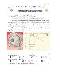
2.1.1 General properties<br />
Figure 2.1 Structures of <strong>Triethylene</strong> <strong>Glycol</strong> (TEG)<br />
Physical form of TEG is a colorless, odorless <strong>and</strong> stable liquid with high viscosity <strong>and</strong> a<br />
high boiling point. It is also soluble in ethanol, acetone, acetic acid, glycerin, pyridine <strong>and</strong><br />
aldehydes; slightly soluble in diethyl ether; <strong>and</strong> insoluble in oil, fat <strong>and</strong> hydrocarbons. The<br />
physical <strong>and</strong> chemical properties of triethylene glycol are shown in Table 2.1.<br />
Table 2.1 Physical <strong>and</strong> Chemical Properties of <strong>Triethylene</strong> glycol (TEG)<br />
Parameter Unit Properties<br />
Common name - <strong>Triethylene</strong> <strong>Glycol</strong><br />
Chemical name - <strong>Triethylene</strong> <strong>Glycol</strong><br />
CAS registry number - 112-27-6<br />
Empirical formula - C6H14O4<br />
Molecular weight g/mol 150.17<br />
Density g/cm 3 1.10<br />
Flash point (PMCC) °C (°F) 176 (350)<br />
Ignition point, °C (˚F) °C (°F) 371 (700)<br />
Distillation range at 760 mm Hg<br />
Initial boiling point<br />
Dry point<br />
4<br />
°C (°F)<br />
278 (532)<br />
300 (572)<br />
Boiling point at 760 mm Hg °C (°F) 287.8 (550)<br />
Freezing point °C (°F) -7.2 (19)<br />
Coefficient of expansion per °C at 20°C - 0.00068<br />
Surface tension at 20°C dyne/cm 45.2<br />
Vapor pressure at 20°C mm Hg less than 0.01<br />
Specific Gravity - 1.1274<br />
Solubility - Highly miscible in water<br />
Source: Material Safety Data Sheet (2012)
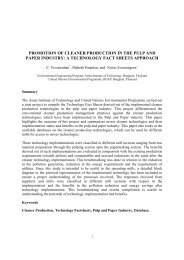
2.1.2 Uses of TEG (<strong>Triethylene</strong> glycol)<br />
The main uses for triethylene glycol are based upon its hygroscopic quality. TEG used as<br />
a dehydrating agent for natural gas pipelines where it removes the water <strong>from</strong> the gas<br />
before being condensed <strong>and</strong> reused in the system. Moreover, TEG also has a<br />
dehumidifying agent in air-conditioning units. TEGs used to make chemical intermediates<br />
such as plasticizers <strong>and</strong> polyester resins. In addition, TEG is used in many products<br />
including automotive antifreeze, brake fluids <strong>and</strong> industrial solvents (Leth <strong>and</strong> Gregersen,<br />
2005), <strong>and</strong> TEG is also used as a solvent in many applications, including as a selective<br />
solvent for aromatics, <strong>and</strong> a solvent in textile dyeing. <strong>Triethylene</strong> glycol also has mild<br />
disinfectant qualities <strong>and</strong>, when volatized, is used as an air disinfectant for virus <strong>and</strong><br />
bacteria control.<br />
Manufacture of<br />
Ester<br />
Derivatives, 12<br />
Miscellaneous,<br />
19<br />
Solvent, 11<br />
Figure 2.2 Major uses of TEG (Alberta Environment, 2012)<br />
However, the usage of TEG as adsorbent in gas dehydration may affect human, animal <strong>and</strong><br />
contaminate in the environment. TEG may transport into soil, release into the river, <strong>and</strong><br />
accumulate in sediment at the bottom of the river by rapid run off during the rainy season<br />
<strong>and</strong> finally affect aquatic <strong>and</strong> human health.<br />
2.1.3 Distribution in environment<br />
No information was found that would indicate DEG (diethylene glycol), TEG, or TREG<br />
(tetraethylene glycol) occur naturally in the environment. Accordingly, their distribution in<br />
the environment is expected to be strongly biased towards facilities where these<br />
compounds are produced or used. The number of facilities where the <strong>Glycol</strong>s are used is<br />
significant. In the U.S., national surveys of occupational hazards were carried out in 1974<br />
<strong>and</strong> 1983. The 1983 survey indicated that the number of facilities where these glycols was<br />
used <strong>and</strong> the number of employees exposed to each was:<br />
5<br />
Vinyl<br />
Pkasticizer, 13<br />
Natural Gas<br />
Dehydration,<br />
45
Table 2.2 The Number of Facilities of <strong>Glycol</strong>s was Used <strong>and</strong> The Number of<br />
Employees Exposed<br />
<strong>Glycol</strong> Number of Facilities Number of Employees Exposed<br />
DEG 55,518 890,145<br />
TEG 23,174 233,613<br />
TREG 3,704 55,282<br />
Source: Alberta Environment (2012)<br />
The physical <strong>and</strong> chemical properties of these glycols (Table2.1) control the environmental<br />
media in which they are likely to be found. All three glycols have very low vapor<br />
pressures, <strong>and</strong> accordingly, their presence in the atmosphere will not be significant. All the<br />
<strong>Glycol</strong>s could potentially be present in soil, groundwater, <strong>and</strong>/or surface water (Table 2.3)<br />
in the vicinity of facilities where they are used.<br />
<strong>Glycol</strong> releases <strong>from</strong> oil <strong>and</strong> gas facilities can occur as a result of leaks <strong>from</strong> operating<br />
equipment or through the improper disposal of wastes when glycol-using facilities are<br />
maintained.<br />
Spills <strong>and</strong> releases of DEG, TEG, <strong>and</strong> TREG at gas plants are remediated where possible.<br />
In Alberta, frequency of spill reporting <strong>and</strong> concentrations of DEG are generally higher<br />
than TEG <strong>and</strong> TREG, with TREG typically having concentrations less than 10 mg/kg or<br />
non-detectable concentrations.<br />
Table 2.3 Surface Water Quality Guidelines for DEG <strong>and</strong> TEG<br />
Water Use DEG (mg/L) TEG (mg/L)<br />
Human drinking water<br />
(Source Guidance value for groundwater)<br />
6 60<br />
Freshwater aquatic life 150 350<br />
Irrigation 1 n/c n/c<br />
Livestock watering 2 n/c n/c<br />
Wildlife watering 3 Source: Alberta Environment (2010)<br />
Notes: n/c = not calculated<br />
n/c n/c<br />
1. Guideline protective of irrigation not calculated due to lack of toxicity data relevant to<br />
irrigation.<br />
2. Guideline not calculated due to the lack of toxicity information for livestock species.<br />
3. Guideline not calculated due to the lack of toxicity information for wildlife species.<br />
2.1.4 Toxic effects<br />
TEG has been hazards Identification both of potential Acute Health Effects <strong>and</strong> Potential<br />
Chronic Health Effects in human <strong>and</strong> animals are limited information <strong>from</strong> animal studies<br />
reveals a range of acute toxic effects overlapping those for DEG (Alberta Environment,<br />
2010). Smyth et al. (1941) found that rats <strong>and</strong> guinea pigs fed TEG at doses approaching<br />
the LD50 appeared sluggish (possibly indicating depression of the central nervous system)<br />
<strong>and</strong> gross examination revealed kidney damage. Oral LD50 values for laboratory animals<br />
range <strong>from</strong> 8,800 to 22,000 mg/kg. Ocular <strong>and</strong> dermal studies found TEG to be non-irritant<br />
6
or mildly irritating. Moreover, for chronic toxic Fitzhugh <strong>and</strong> Nelson (1946) exposed male<br />
rats to 4% TEG in their diet (approximately 2,000 mg/kg bw/day) for 2 years. No effects<br />
on mortality, body weight, blood <strong>and</strong> urine composition, <strong>and</strong> gross <strong>and</strong> microscopic<br />
appearance of the major organs was reported.<br />
In human are very hazardous in case of eye contact (irritant) of ingestion <strong>and</strong> slightly<br />
hazardous in case of inhalation. Inflammation of the eye is characterized by redness,<br />
watering, <strong>and</strong> itching, which there primary method of prevention <strong>and</strong> medical care is<br />
showed in table 2.4. TEG has a very low order of acute toxicity by perioral, percutaneous<br />
<strong>and</strong> inhalation (vapor <strong>and</strong> aerosol) routes of exposure. It does not produce primary skin<br />
irritation. Acute eye contact with the liquid causes mild local transient irritation<br />
(conjunctiva hyperemia <strong>and</strong> slight chemosis) but does not induce corneal injury. Robertson<br />
et al (1947) exposed rats to TEG in their drinking water at 3,000 mg/kg bw/day for 13<br />
months. No effects on mortality, body weight, blood <strong>and</strong> urine composition, <strong>and</strong> gross <strong>and</strong><br />
microscopic appearance of the major organs was reported. Bossert et al (1992) exposed<br />
mice to drinking water containing TEG for 14 weeks. No effects were seen at 3,300 mg/kg<br />
bw/day, but increased liver weight was observed at 6,800 mg/kg bw/day.<br />
Animal maximization <strong>and</strong> human volunteer repeated insult patch tests studies have shown<br />
that TEG does not cause skin sensitization (Ballantyne et al., 2007). The use patterns<br />
suggest that exposure to TEG is mainly occupational, with limited exposures by<br />
consumers. Exposure is normally by skin <strong>and</strong> eye contact. Local <strong>and</strong> systemic adverse<br />
health effects by cutaneous exposure are likely not to occur, <strong>and</strong> eye contact will produce<br />
transient irritation without corneal injury. The very low vapor pressure of TEG makes it<br />
unlikely that significant vapor exposure will occur. Aerosol exposure is not a usual<br />
exposure mode, <strong>and</strong> acute aerosol exposures are unlikely to be harmful, although a<br />
peripheral sensory irritant effect may develop.<br />
However, repeated exposures to a TEG aerosol may result in respiratory tract irritation,<br />
with cough, shortness of breath <strong>and</strong> tightness of the chest. Recommended protective <strong>and</strong><br />
precautionary measures include protective gloves, goggles or safety glasses <strong>and</strong><br />
mechanical room ventilation. LC50 data to various fish, aquatic invertebrates <strong>and</strong> algae,<br />
indicate that TEG is essentially nontoxic to aquatic organisms. Also, sustained exposure<br />
studies have demonstrated that TEG is of a low order of chronic aquatic toxicity. The<br />
bioconcentration potential, environmental hydrolysis <strong>and</strong> photolysis rates are low, <strong>and</strong> soil<br />
mobility high. In the atmosphere TEG is degraded by reacting with photochemically<br />
produced hydroxyl radicals. These considerations indicate that the potential for<br />
ecotoxicological effects with TEG is low Carcinogenicity <strong>and</strong> Mutagenicity (Ballantyne et<br />
al., 2007).<br />
7
Table 2.4 The Primary Method of Prevention <strong>and</strong> Medical Care of Human<br />
Identification of hazards Prevention<br />
1. Potential Acute Health Effects:<br />
Eye contact (irritant)<br />
Inhalation (Slightly hazardous)<br />
Skin contact<br />
Ingestion<br />
2. Potential Chronic Health Effects:<br />
Carcinogenic effects<br />
Mutagenic effects<br />
Affecting organs inside the body.<br />
Source: Material Safety Data Sheet (2012)<br />
8<br />
Check for <strong>and</strong> remove any contact lenses.<br />
Immediately flush eyes with running water<br />
for at least 15 minutes, keeping eyelids<br />
open.<br />
Cold water may be used.<br />
Do not use an eye ointment.<br />
Seek medical attention.<br />
Allow the victim to rest in a well-ventilated<br />
area.<br />
Seek immediate medical attention<br />
No known effect on skin contact, rinse with<br />
water for a few minutes.<br />
Do not induce vomiting.<br />
Loosen tight clothing such as a collar, tie,<br />
belt or waistb<strong>and</strong>.<br />
If the victim is not breathing, perform<br />
mouth-to-mouth resuscitation.<br />
Seek immediate medical attention.<br />
Not available<br />
Not available<br />
The substance is toxic to kidneys, the<br />
nervous system.<br />
Repeated or prolonged exposure to the<br />
substance can produce target organs<br />
damage.
2.2 Gas <strong>Separation</strong> Plants (GSPs)<br />
2.2.1 Characteristics of TEG in wastewater <strong>from</strong> gas separation plant<br />
In the present, natural gas is one of the most important fuels in our life <strong>and</strong> one of the<br />
principle sources of energy for many of our day-to-day needs <strong>and</strong> activities. It is an<br />
important factor for the development of countries that have strong economy because it is a<br />
source of energy for household, industrial <strong>and</strong> commercial use, as well as to generate<br />
electricity. Most natural gas producers use TEG to remove water in the dehydration<br />
process. When TEG is placed into contact with natural gas it strips the water out of the gas.<br />
Thus, TEG is one of the major components of the wastewater originates <strong>from</strong> a Gas<br />
<strong>Separation</strong> Plants (GSPs).<br />
Moreover, the raw natural gas contains water vapor, hydrogen sulfide (H2S), carbon<br />
dioxide, helium, nitrogen, <strong>and</strong> other compounds showed in table 2.5. In order to meet the<br />
requirements for a clean, dry, wholly gaseous fuel suitable for transmission through<br />
pipelines <strong>and</strong> distribution for burning by end users, the gas must go through several stages<br />
of processing, including the removal of entrained liquids <strong>from</strong> the gas, followed by drying<br />
to reduce water content.<br />
Table 2.5 The Composition of Natural Gas<br />
Components Symbol Percentage (%)<br />
Methane CH4 70-90<br />
Ethane C2H6<br />
Propane C3H8<br />
0-20<br />
Butane C4H8<br />
Carbon Dioxide CO2 0-8<br />
Oxygen O2 0-0.2<br />
Nitrogen N2 0-05<br />
Hydrogen Sulphide H2S 0-5<br />
Rare Gases He,Ne,Xe trace<br />
Source: Composition of natural gas (2012)<br />
In addition, the types of dehydration process used are absorption, adsorption, gas<br />
permeation <strong>and</strong> refrigeration. The most widely dehydration processes used are which<br />
usually involves one of two processes: either absorption, or adsorption. Absorption occurs<br />
when the water vapor is taken out by a dehydrating agent. Adsorption occurs when the<br />
water vapor is condensed <strong>and</strong> collected on the surface.<br />
In part of TEG, The TEG adsorbs water <strong>from</strong> the wet gas <strong>and</strong> is passed to the glycol<br />
regeneration unit where, very simply, adsorbed gases are flashed off <strong>and</strong> the water is<br />
removed <strong>from</strong> the reboiler by heating the wet glycol to around 400ºF at atmospheric<br />
conditions gas. The processes are continuous, that is glycol flow continuously through<br />
dehydration unit where they come in contact <strong>and</strong> the glycol absorbs the water. The<br />
regenerated TEG is then pumped back to the dehydration unit inlet. Thus, TEG is one of<br />
the major components of the wastewater originates <strong>from</strong> a Gas <strong>Separation</strong> Plants (GSPs).<br />
Therefore it is absolutely essential to recover <strong>and</strong> reuse TEG, back in the production<br />
process.<br />
9
Furthermore, in this study is case of PTT (Petroleum Authority of Thail<strong>and</strong>) which is the<br />
largest operator of gas separation plants in Thail<strong>and</strong>. PTT’s gas separation plant unit 1 was<br />
started operating on 1985, with unit 2 to 5 coming up later on. In addition, unit 1, 2, 3 <strong>and</strong><br />
5 are located in Rayong province <strong>and</strong> have production capacity of 390, 290, 390 <strong>and</strong> 530<br />
MMSCFD (Million st<strong>and</strong>ard cubic feet per day respectively). Unit 4 is located in Kanhom,<br />
Nakhon Srithammarat provinces <strong>and</strong> has current production capacity of 170.<br />
PTT is having another two projects on construction in Rayong. The two new plants are the<br />
ethane separation plant (ESP) <strong>and</strong> the gas separation plant unit 6. The ethane separation<br />
plant’s purpose is to improve production of the gas separation plant unit 2 <strong>and</strong> 3. The gas<br />
separation plant unit 6 has the production capacity of 800 MMSCFD. Both projects<br />
encourage development of petrochemical industry <strong>and</strong> production of liquefied natural<br />
(Cooking Gas) in response of the domestic dem<strong>and</strong>. The total production capacity of<br />
PTT’s gas separation plant will increase to 2,640 MMSCFD, which showed in table 2.6.<br />
Table 2.6 Total Production Capacity of PTT’s Gas <strong>Separation</strong> Plant<br />
Gas separation Capacity<br />
(MMSCFD)<br />
Production Capacity (Million Tons per Year)<br />
GSP Unit 1-5 ESP <strong>and</strong> GSPs Total<br />
1,770 870 2,640<br />
Ethane 1.1 1.3 2.4<br />
Propane & LPG 2.5 1.1 2.6<br />
NGL 0.5 0.2 0.7<br />
Total 4.1 2.6 6.7<br />
Source: PTT Research & Technology Institute (2012)<br />
Note: MMSCFD = Million st<strong>and</strong>ard cubic feet per day<br />
Gas separation plants are located in Rayong of Thail<strong>and</strong>; there are 2 sources of TEG<br />
wastewater as follow in table 2.7 <strong>and</strong> figure 2.3.<br />
Figure 2.3 Source of TEG wastewater in GSPs of PTT (Thail<strong>and</strong>)<br />
10
Table 2.7 Sources of TEG Wastewater Treatment Plant<br />
Wastewater treatment plant Detail<br />
Wastewater 1: (TEG low concentrations) - Volume 10-12 m 3 /day with concentration<br />
of TEG 0.4%<br />
11<br />
- Half is send to the wastewater treatment<br />
plant in industry which treatment with<br />
AOP (Advanced Oxidation process)<br />
system; another half is send external<br />
disposal.<br />
Wastewater 2: (TEG high concentrations) - Volume 1 m 3 /day with concentration of<br />
TEG 5-70%<br />
Source: PTT Research & Technology Institute (2012)<br />
2.3 Treatment Process<br />
- Send to Better world green company for<br />
disposal (2,700 bath/tons)<br />
TEG wastewater in PTT of Thail<strong>and</strong> uses conventional wastewater treatments. Moreover,<br />
consisting process physical Treatment, minimizing Complex Structure of Organic<br />
Compounds, biological treatment <strong>and</strong> MBR (<strong>Membrane</strong> Bio reaction) system, which have<br />
effluent Characteristics are show in table 2.8.<br />
Orecki et al., 2006 found that almost use membrane filtration for separation of EG<br />
(ethylene glycol) <strong>from</strong> wastewater by nanofiltration. These studies was to use the two<br />
membrane module configurations-spiral wound (equipped with membranes: NF270-2540)<br />
<strong>and</strong> NF90-2540) <strong>and</strong> tubular (equipped with membranes AFC 30) for separation of EG.<br />
Nik et al., 2005 found that inorganic membranes <strong>and</strong> particular zeolite membranes are<br />
usually used for the dehydration of organic solvent by pervaporation (PV). In this study on<br />
the pervaporation dehydration of EG/water mixtures using commercial nanoporous NaA<br />
zeolite membranes.<br />
Jehle et al., 1995 develop the evaporation (EV), for the concentration of the coolant liquid<br />
<strong>from</strong> 25% up to 70% glycol. The ethylene glycol concentration in the overhead product<br />
remains as low as 0.5% for this concentration range. Using two different pressures 13.3<br />
<strong>and</strong> 133.3 mbar at 75°C. The tests of pervaporation (PV) were carried out with a mixture of<br />
the original coolant liquid diluted with water at ethylene glycol concentrations in the range<br />
of 70-95% at 75°C <strong>and</strong> using different pressure 20-30 mbar. The tests of reverse osmosis<br />
(RO) were detailed with pressure between 15 <strong>and</strong> 70 bar <strong>and</strong> temperature between 15 <strong>and</strong><br />
40 °C which has the initial glycol feed concentration 0.5%-5%. Furthermore, reverse<br />
osmosis <strong>and</strong> pervaporation to separation of glycol <strong>and</strong> water <strong>from</strong> coolant liquids which<br />
have the pre-treatment process by gravity separation to free oil <strong>and</strong> settleable solids before<br />
pass through membrane filtration.
Table 2.8 Discharged Effluent Characteristics of Gas <strong>Separation</strong> Plants<br />
Parameter Unit Effluent St<strong>and</strong>ard<br />
pH - 7.9 5.5-9.0<br />
TEG %<br />
< 2 ppm<br />
(at influent of ozone tank)<br />
-<br />
TDS mg/L 1254 3000<br />
TSS mg/L 2.9 50<br />
BOD mg/L 4 20<br />
COD mg/L 42 120<br />
Oil & Grease mg/L 0.5 5<br />
Cl mg/L 417 -<br />
TKN mg/L 2.7 100<br />
Hg mg/L 0.0001 0.005<br />
Zn µg/L 0.58 5<br />
Total Coli form MPN 100 mL 220
mineral, pharmaceutical, electronics, beverages, beer/wine clarification, as well as<br />
wastewater purification <strong>and</strong> water desalination. <strong>Membrane</strong> separation processes compete<br />
with conventional processes such as carbon adsorption, solvent extraction, distillation,<br />
centrifugation, flocculation followed by multimedia filtration, <strong>and</strong> ion-exchange.<br />
Compared to conventional separation, membrane processes offers several advantages, such<br />
as high quality products, the requirement for less chemical addition, <strong>and</strong> easier control of<br />
operation <strong>and</strong> maintenance. However, membrane fouling is still hampering the growth of<br />
industrial applications of membranes (Richard, 2012).<br />
2.4.2 Introduction to membrane process<br />
<strong>Membrane</strong> is receiving special recognition as alternatives to conventional water treatment<br />
<strong>and</strong> as a means of polishing treated wastewater effluent especially in reuse applications. It<br />
is defined as a thin film separation of two or more components <strong>from</strong> fluid flow <strong>and</strong> can be<br />
classified differently on the basis of determined criteria like type of materials, fluid<br />
movement, morphology, pore size etc. The need for more efficient treatment processes has<br />
attracted the attention of environmental scientists <strong>and</strong> engineers towards pressure-driven<br />
membrane techniques. The application of membrane filtration processes not only enables<br />
high removal efficiencies, but also allows reuse of water <strong>and</strong> some of the valuable waste<br />
constituents. In the last few years, technical <strong>and</strong> economic improvement has made the<br />
treatment of industrial wastewater by membrane system even more advantageous.<br />
Ultrafiltration has been successfully applied for recycling high molecular weight <strong>and</strong><br />
insoluble dyes, auxiliary chemicals <strong>and</strong> water. However, ultrafiltration does not remove<br />
low molecular weight <strong>and</strong> soluble dyes (acid, direct, reactive <strong>and</strong> basic, etc.) but efficient<br />
color removal has been achieved by nanofiltration. Its apparent benefits over other<br />
advanced treatments are including continuous separation, low energy consumption, easy<br />
combination with other existing technique, easy up-scaling, <strong>and</strong> no chemical cost.<br />
Excepting water/wastewater treatment, membrane process can be found in all industrial<br />
areas such as food <strong>and</strong> beverages, metallurgy, pulp <strong>and</strong> paper, textiles, pharmaceutical,<br />
automotive, dairy, biotechnology <strong>and</strong> chemical industry. <strong>Membrane</strong> is widely used in<br />
industrial process <strong>and</strong> used for chemical recovery.<br />
As mentioned above, membrane can be manufactured by a wide variety of materials<br />
included inorganic <strong>and</strong> organic membrane. The inorganic membranes may be distinguished<br />
to 4 types such as ceramic, glass, metallic <strong>and</strong> zeolite membranes. Their advantages are<br />
high chemical, mechanical <strong>and</strong> thermal stabilities but the disadvantages are very fragile<br />
<strong>and</strong> expensive. The organic membranes are widely used in water <strong>and</strong> wastewater<br />
applications they are more flexible <strong>and</strong> can be put in compact module. It can be made <strong>from</strong><br />
cellulose <strong>and</strong> synthetic polymer. The synthetic polymer can be manufactured for open<br />
porous membranes, which are applied for microfiltration <strong>and</strong> ultrafiltration <strong>and</strong> dense<br />
nonporous membrane, applied in gas separation <strong>and</strong> pervaporation. The summarized<br />
details of each are explained as following.<br />
Microfiltration (MF)<br />
It is most similar to conventional coarse filtration, the pore size range <strong>from</strong> 100 - 1000 nm<br />
<strong>and</strong> driving force pressure is less than 4 bars. It is mainly used to separate suspended <strong>and</strong><br />
colloidal particles by size sieving mechanism. It is applied for various purposes in industry<br />
such as analytical application, sterilization in food <strong>and</strong> pharmaceuticals, ultrapure water<br />
production in semiconductors, clarification, algae cell harvesting, water treatment <strong>and</strong><br />
13
membrane bioreactor in wastewater treatment. MF membranes are made <strong>from</strong> a number of<br />
organic <strong>and</strong> inorganic materials, for example:<br />
- Polymeric membranes: polyamide (PA), polysulphone (PS), polyethersulphone<br />
(PES), polypropylene (PP), polycarbonate (PC).<br />
- Ceramic membranes: alumina (Al2O3), zirconia.<br />
MF is used primarily for separating macromolecules, large suspended particles, fungi <strong>and</strong><br />
bacteria. It is finding increased application as a pretreatment method to other membrane<br />
processes, in pharmaceutical applications (Meltzer <strong>and</strong> Blakie, 1987) as a replacement for<br />
conventional clarification <strong>and</strong> filtration technologies (Noble <strong>and</strong> Stern, 1995).<br />
Ultrafiltration (UF)<br />
The pore size is <strong>from</strong> 10–100 nm. Ultrafiltration (UF) is a variety of membrane filtration in<br />
which hydrostatic pressure forces a liquid against a semipermeable membrane. Suspended<br />
solids <strong>and</strong> solutes of high molecular weight are retained, while water <strong>and</strong> low molecular<br />
weight solutes pass through the membrane. This separation process is used in industry <strong>and</strong><br />
research for purifying <strong>and</strong> concentrating macromolecular (10 3 -10 6 Da) solutions,<br />
especially protein solutions. Ultrafiltration is not fundamentally different <strong>from</strong><br />
microfiltration <strong>and</strong> nanofiltration except in terms of size of molecules it retains. The<br />
applications beyond microfiltration are including metallurgy (oil-water emulsion, electro<br />
paint recovery), textile, etc.<br />
UF has been accepted as an alternative to conventional pretreatment for brackish surface<br />
water <strong>and</strong> sea water reverse osmosis (SWRO) systems (De et al., 2002). The use of UF<br />
systems as RO pretreatment has some significant advantages over RO systems designed to<br />
include conventional pretreatment:<br />
- UF membrane systems take up less than 50% of the area of a conventional<br />
pretreatment system, which results in reduced construction costs. This means that<br />
a UF membrane system may be more favorable in cases where space is limited, or<br />
where the costs of civil works are high.<br />
- UF membranes system is easier to operate than some conventional filtration<br />
processes.<br />
- The operating costs of a UF membrane system may be lower than those for<br />
conventional pretreatment systems.<br />
- UF concentrated waste streams are easier to dispose of relative to those <strong>from</strong><br />
chemically enhanced conventional pretreatment processes.<br />
- UF filtrate quality is usually better than that of conventional pretreatment process.<br />
The colloidal fouling load to the RO is reduced, with a significantly lower Silt<br />
Density Index (SDI) <strong>and</strong> turbidity in the feed water.<br />
Nanofiltration (NF)<br />
It is used for removal of low molecular weight solutes such as inorganic salts or small<br />
organic molecules. Its pore size is in range of 1–10 nm <strong>and</strong> the operating pressure is 3-20<br />
bars. The applications are including desalination of brackish water, removal of micro<br />
pollutants, water softening, wastewater treatment, rejection of dyes, etc<br />
14
Reverse osmosis (RO)<br />
The pore size is almost similar with nanofiltration but percentages of salt rejection are<br />
different. The driving pressure is in range of 10-100 bars. The applications are including<br />
desalination of brackish <strong>and</strong> seawater, production of ultrapure water for electronic<br />
industry, concentration of food juice, sugar <strong>and</strong> milk, etc.<br />
Microfiltration<br />
100 – 1000 nm<br />
Colloids, Virus<br />
Color<br />
Hardness<br />
Pesticides<br />
Salt<br />
Water<br />
Figure 2.5 Demonstrates main characteristics of each membrane types<br />
2.4.3 Types of filtration<br />
Ultrafiltration<br />
10 – 100 nm<br />
Typically, membrane filtration can be classified to 2 types including cross flow <strong>and</strong> deadend<br />
filtrations depending on application <strong>and</strong> module configuration. The prior provides<br />
lower fouling rate <strong>and</strong> smaller flux decline than the later. Because of the cross-flow<br />
operation can minimize fouling <strong>and</strong> cake layer formation on membrane with adjustment of<br />
cross-flow velocity of feed. In case of dead-end filtration, even though it causes large<br />
membrane fouling, its strength is high water recovery relative to cross flow type.<br />
NF <strong>and</strong> RO are mostly applied with cross flow type because they tend to have fouling as<br />
compared to other bigger pore of membranes. In case of MF, dead-end filtration is<br />
frequently applied whereas both of cross flow <strong>and</strong> dead-end operations are applied in UF.<br />
15<br />
Nanofiltration<br />
1 – 10 nm<br />
Reverse Osmosis<br />
< 10 nm<br />
ΔP = 0.1-4 bar ΔP = 0.2-10 bar ΔP = 3-20 bar ΔP = 10-100 bar<br />
Color<br />
Hardness<br />
Pesticides<br />
Salt<br />
Water<br />
Salt<br />
Water<br />
Water
Table 2.9 Detail Explanation of Different <strong>Membrane</strong> Processes<br />
<strong>Membrane</strong><br />
Pressure driven membrane processes<br />
Microfiltration Ultrafiltration Nanofiltration Reverse Osmosis Piezodialysis<br />
symmetric<br />
porous<br />
Asymmetric<br />
porous<br />
Thickness ≈ 10-150 µm ≈ 150µm<br />
16<br />
Composite<br />
Sub layer ≈ 150<br />
µm<br />
Top layer
Clean <strong>Membrane</strong> Fouled <strong>Membrane</strong><br />
Figure 2.6 <strong>Membrane</strong> fouling<br />
The selectivity of membrane toward diluted mixture is generally expressed by percentage<br />
of rejection (R), demonstrated as follows;<br />
C p<br />
% R 1100 <br />
<br />
C <br />
f <br />
Where Cp = solute concentration in permeate<br />
Cf = solute concentration in feed<br />
2.4.5 Factors affecting membrane filtration<br />
2.4.5.1 Hydrophobicity/hydrophilicity of membrane<br />
17<br />
Equation.2.2<br />
Hydrophobicity/hydrophilicity of membrane is described for its ability to allow water<br />
passing through. It is investigated by measurement of contact angle of water droplet on<br />
membrane surface. Greater than 90˚ of contact angel indicates that the membrane has low<br />
affinity to water (hydrophobicity) leading to low permeate flux as compared to hydrophilic<br />
one. Moreover, hydrophobicity of membrane also affects removal of organic compound.<br />
2.4.5.2 pH<br />
pH of solution relates to presenting charge of membrane <strong>and</strong> a compound beside it<br />
involves proton dissociation of functional group, attached on membrane surface or<br />
composed in compounds. Thus, it directly affects electrostatic forces between compound<br />
<strong>and</strong> membrane surface. Zeta potential is defined as power of charges showing on<br />
membrane surface. The negatively charged membrane has been reported to highly reject<br />
negatively charged organic compound through electrostatic repulsion (Bellona et al.,<br />
2004). However, the electrostatic repulsion was reported to decrease with feed containing<br />
some contaminants such as salts (Na + , Mg 2+ , etc.). It resulted because the positive ions
dissolved in solution might adsorb negative charge on membrane leading to decreasing<br />
membrane rejection through electrostatic repulsion.<br />
However, low rejection of negatively charged compound has also been observed with<br />
negatively charged membrane. McCallum et al. (2008) demonstrated decreasing rejection<br />
of estrogen processing negative charges by predominantly negative-charged polyamide<br />
membrane.<br />
2.4.5.3 Organic matter<br />
From literature review, the presence of organic matter showed different effects on<br />
membrane filtration as follows;<br />
1. Decreasing rejection<br />
A number of researches demonstrated adverse effect of organic matter on membrane<br />
filtration of some organic pollutants. Yoon et al. (2006) found that natural organic matter<br />
decreased rejection of nanofiltration. They explained that it might be resulted <strong>from</strong><br />
competition between natural organic matter <strong>and</strong> pollutants on sorption site of membrane.<br />
Their explanation is similar with a number of researches that organic matter caused<br />
pollutants (McCallum et al., 2008 <strong>and</strong> Zhang et al., 2006).<br />
2. Increasing rejection<br />
Comerton et al. (2008) found that rejection of pollutants prepared in filtered lake sample<br />
was higher than in Milli-Q water with tight NF membrane. They concluded that in addition<br />
to membrane pore size, water matrices play important role on rejection by improving<br />
configuration or properties of membrane surface. Moreover, it is interesting to find that<br />
feed prepared with secondary effluent <strong>from</strong> MBR showed significant membrane fouling<br />
than natural water, even though it provided lower rejection (Comerton et al., 2008). Hence,<br />
chemical properties of water matrices relates to fouling characteristics <strong>and</strong> membrane<br />
rejection.<br />
2.4.6 Potential membrane filtration (Nanofiltration <strong>and</strong> Reverse osmosis)<br />
2.4.6.1 Reverse Osmosis/Nanofiltration (RO/NF)<br />
There are only few researches that applied membranes (RO <strong>and</strong> NF) for TEG recovery in<br />
wastewater. Due to in efficiency of conventional treatment systems, nanofiltration (NF)<br />
frequently becomes the chosen treatment process. NF has been recognized having the<br />
properties in between UF <strong>and</strong> reverse osmosis (RO) <strong>and</strong> thus offers significant advantages,<br />
e.g. lower osmotic pressure difference, higher permeate flux, higher retention of<br />
multivalent salt <strong>and</strong> molecular weight compounds (>300), relatively low investment <strong>and</strong><br />
low operation <strong>and</strong> maintenance costs. Koyuncu et al., 2004 utilized NF membrane to reuse<br />
reactive dyehouse wastewater <strong>and</strong> the rejection of NaCl was about 12% while the 99.9% of<br />
dye in the solution was removed. Comerton et al., 2008, Lee et al., 2008, Yoon et al., 2007,<br />
Nghiem <strong>and</strong> Hawkes, 2007, Plakas et al., 2006 <strong>and</strong> Berg et al., 1997. These researches<br />
investigated efficiency of reverse osmosis <strong>and</strong> nanofiltration on several kinds of those<br />
compounds. In overviews, reverse osmosis showed greater than 90% of removal efficiency<br />
whereas nanofiltration showed lower efficiencies.<br />
18
Table 2.10 Comparison of Rejection Efficiency of Constituents Between NF <strong>and</strong> RO<br />
Constitutes Unit NF RO<br />
Total dissolved solids % 40-60 90-98<br />
Total organic carbon % 90-98 90-98<br />
Color % 90-96 90-96<br />
Hardness % 80-85 90-98<br />
Salts/chloride % 10-50 90-99<br />
Salts/sulphate % 80-95 90-99<br />
Nitrate % 10-30 84-96<br />
Heavy Metals a % 40->50 85-95<br />
Protein log 3-5 4-7<br />
Pathogens (ex:bacteria) log 3-6 4-7<br />
EDCs/PhACs % >10 >90<br />
a = except Cd, Ag <strong>and</strong> Hg<br />
Source: Asano et al.(2007), Lee at al.(2008) <strong>and</strong> Comerton, et al.(2008)<br />
2.4.7 Pervaporation technology<br />
2.4.7.1 Definition of pervaporation process<br />
Pervaporation is a membrane process in which a pure liquid or mixture is in contact with<br />
the membrane on the feed or upstream side at atmospheric pressure <strong>and</strong> where permeate is<br />
removed as a vapor because of a low vapor pressure existing on permeate or downstream<br />
side. This low (partial) vapor pressure can be achieved by employing a carrier gas or using<br />
a vacuum pump. The (partial) downstream pressure must be lower than the saturation<br />
pressure at least. A schematic drawing of this process is show in figure 2.7<br />
Feed Retentate<br />
Condenser<br />
Permeate<br />
Vacuum pump<br />
Carrier gas<br />
Figure 2.7 Schematic drawing of the pervaporation process with a downstream<br />
vacuum or an inert carrier-gas<br />
Essentially, the pervaporation process involves a sequence of the three steps:<br />
Selective sorption into the membrane on feed side<br />
Selective diffusion through the membrane<br />
Desorption into a vapor phase on the permeate side<br />
19<br />
Feed<br />
Condenser<br />
Retentate<br />
Permeate
The driving force for the mass transfer of permeates <strong>from</strong> the feed side to the permeate side<br />
of the membrane is a gradient in chemical potential, which is established by applying a<br />
difference in partial pressures of permeates across the membrane. The difference in partial<br />
pressures can be created either by reducing the total pressure on the permeate side of the<br />
membrane by using a vacuum pump system or by sweeping an inert gas on the permeate<br />
side of the membrane.<br />
Table 2.11 Summary of Pervaporation<br />
<strong>Membrane</strong>s:<br />
Composite membranes with an elastomeric or glassy<br />
polymeric top layer<br />
Thickness: ≈ 0.1 to few μm (for top layer)<br />
Pore size: Nonporous<br />
Driving force: Partial vapors pressure or activity difference<br />
<strong>Separation</strong> principle: Solution/Diffusion<br />
<strong>Membrane</strong> material: Elastomeric <strong>and</strong> glassy polymer<br />
Application: Dehydration of organic solvents<br />
Removal of organic components <strong>from</strong> water<br />
(alcohols, aromatics, chlorinated hydrocarbons)<br />
Polar/Non-polar (e.g. alcohols/aliphatic or<br />
alcohols/aromatics)<br />
Saturated/Unsaturated (e.g. cyclohexane/<br />
benzene)<br />
<strong>Separation</strong> of isomers (e.g. C-8 isomers;<br />
o-xylene, m-xylene, p-xylene, ethyl benzene, styrene)<br />
Source: Reidel et al. (1996)<br />
2.4.7.2 Definition of vapor permeation<br />
Vapor permeation is similar in principle to pervaporation. The only difference concerns the<br />
feed, which is a mixture of vapors or vapors <strong>and</strong> gases. As in pervaporation, the permeate<br />
partial pressure is maintained by use of a vacuum or an inert sweep gas (table 2.11). There<br />
is no change of phase involved in its operation. Thus, compared to pervaporation, the<br />
addition of heat equivalent to the enthalpy of vaporization is not required in the membrane<br />
unit <strong>and</strong> there is no temperature drop along the membrane (Kujawski, 2000). Operation in<br />
the vapor phase also eliminates the effect of the concentration polarization prevalent in<br />
liquid phase separations, such as pervaporation<br />
20
Table 2.12 Overview of Chosen <strong>Membrane</strong> <strong>Separation</strong> Processes (Kujawski, 2000)<br />
<strong>Membrane</strong><br />
process<br />
Feed<br />
phase/permeate<br />
phase<br />
Pervaporation liquid/vapor<br />
Vapor<br />
permeation<br />
vapor/vapor<br />
Pertraction liquid/liquid<br />
Gas separation gas/gas<br />
<strong>Membrane</strong><br />
distillation<br />
liquid/vapor<br />
Driving force <strong>Membrane</strong><br />
Chemical<br />
potential<br />
gradient<br />
Chemical<br />
potential<br />
gradient<br />
Concentration<br />
gradient<br />
Hydrostatic<br />
pressure<br />
gradient<br />
Vapor pressure<br />
gradient<br />
21<br />
Dense,<br />
Hydrophobic<br />
Dense,<br />
Hydrophobic<br />
Dense,<br />
Hydrophobic<br />
Porous or<br />
Dense<br />
Porous or<br />
Dense<br />
Main<br />
Applications<br />
<strong>Separation</strong> of<br />
liquid mixtures<br />
<strong>Separation</strong> of<br />
vapor mixtures or<br />
vapor <strong>from</strong> gases<br />
<strong>Separation</strong> of<br />
organic solutions<br />
<strong>Separation</strong> of<br />
gaseous mixtures<br />
Ultrapure water,<br />
concentration of<br />
solution<br />
Thus, in table 2.12 presents the main characteristics of chosen membrane processes which<br />
resemble pervaporation or vapor permeation concerning either the membranes applied or<br />
type of application. To avoid any misunderst<strong>and</strong>ings it is quite important to know both the<br />
differences <strong>and</strong> similarities of these processes. The performance of a given membrane in<br />
pervaporation or vapor permeation is estimated in terms of its selectivity <strong>and</strong> the permeate<br />
flux. The assessment is based on the mass transfer of the preferentially permeating species,<br />
regardless of whether permeate or the retentate is the target product of the pervaporation<br />
process (Kujawski, 2000).<br />
2.4.7.3 Operational parameters<br />
The selectivity of a given membrane can be estimated by using the following two<br />
dimensionless parameters. The equation 2.3 is used to determine separation factor <strong>and</strong><br />
equation 2.1 for determine permeate flux as follows:<br />
<strong>Separation</strong> Factor ()<br />
water/ org<br />
Cwater / Corg<br />
Cwater / Corg<br />
permeate<br />
Equation 2.3<br />
Where Corg = Denote the weight fraction of organic, gram (kg)<br />
Cwater = Denote the weight fraction of water component, gram (kg)<br />
feed
2.4.7.4 Variables that affect the performance of pervaporation.<br />
Feed concentration<br />
Due to the concentration of the preferentially permeating (usually minor) solution<br />
component, being depleted in the process. There are two aspects to be considered the<br />
activity of the target component in the feed <strong>and</strong> the solubility of the target component in<br />
the membrane.<br />
<strong>Membrane</strong> thickness<br />
Refers to dry thickness because flux is inversely proportional to membrane thickness, thin<br />
a membrane favors the overall flux but decrease selectivity. Moreover, thin membranes are<br />
used for low swelling glassy membranes <strong>and</strong> thick membranes are used for high swelling<br />
elastomeric membranes to maintain the selectivity.<br />
Permeate pressure<br />
Permeate pressure provides the driving force in pervaporation which the permeation rate of<br />
any feed component increases as its partial permeate pressure is lowered. The highest<br />
conceivable permeate pressure is the vapor pressure of the penetrant in the liquid feed.<br />
Moreover, the effect of this parameter on pervaporation performance is dictated by the<br />
magnitude of the vapor pressures encountered, <strong>and</strong> by the difference in vapor pressures<br />
between them.<br />
Temperature<br />
Feed temperature or any other representative between feed <strong>and</strong> retentate streams. The feed<br />
liquid provided the heat of vaporization of permeate, <strong>and</strong> in consequence there is a<br />
temperature loss between the feed <strong>and</strong> retentate stream where the membrane act as a heat<br />
exchanger barrier. Furthermore, temperature affects solubility <strong>and</strong> diffusivity of all<br />
permeates, as well as the extent of mutual interaction between them. Favoring the flux <strong>and</strong><br />
having minor effect on selectivity.<br />
2.4.7.5 Type of membranes <strong>and</strong> membrane modules<br />
The choice of the membrane strongly depends on the type of application. It is important<br />
which of the component should be separated <strong>from</strong> the mixture <strong>and</strong> whether this component<br />
is water or an organic liquid.<br />
Table 2.13 Types of <strong>Membrane</strong> for Pervaporation (Reidel et al., 1996)<br />
Hydrophilic Hydrophobic<br />
Polyacrylonitrile (PAN) Polydimethylsiloxane (PDMS)<br />
Polyvinyl alcohol (PVA) Polyoctylmethylsiloxane (POMS)<br />
Polyacrylic acid (PAA) Polyether block amide (PEBA)<br />
Chitosan (CS)<br />
22
Hollow fiber module<br />
This module is used with an inside–out configuration to avoid increase in permeate<br />
pressure within the fibers, but the outside–in configuration can be used with short fibers.<br />
Another advantage of the inside-out configuration is that the thin top layer is better<br />
protected but higher membrane area can be achieved with the outside-in configuration.<br />
Plate <strong>and</strong> Frame module<br />
Figure 2.8 Hollow fiber modules (Xu, 2001)<br />
Two adjacent membrane pairs <strong>and</strong> then the feed solution flows through the membrane<br />
between each pair of modules are composed of a double membrane or a sequence of<br />
stacked layers horizontally. Moreover, the other devices to determine which making the<br />
flow of retentate <strong>and</strong> permeated.<br />
Spiral wound module<br />
Figure 2.9 Plate-<strong>and</strong>-frame modules<br />
This module is very similar to the plate <strong>and</strong> frame system but has a greater packing<br />
density. This type of module is used with organophilic membranes to achieved organic–<br />
organic separations.<br />
23
Tubular modules<br />
Figure 2.10 Spiral wound module (Xu, 2001)<br />
Inorganic (ceramic) membranes are produced mainly as tubes, <strong>and</strong> then the obvious<br />
module is the tube bundle for applications that used this kind of membranes. On the other<br />
h<strong>and</strong>, for sweep gas pervaporation, tubular membranes conducting the gas-permeate<br />
mixture are the only option.<br />
Figure 2.11 Tubular modules (Xu, 2001)<br />
The difference <strong>and</strong> similarity between different pervaporation modules are summarized in<br />
table 2.13<br />
Table 2.14 Comparison of Pervaporation Modules (Xu, 2001)<br />
Hollow<br />
Fine<br />
Fibers<br />
Capillary<br />
Fibers<br />
24<br />
Spiral-<br />
Wound<br />
Plate-<strong>and</strong>-<br />
Frame<br />
Tubular<br />
Manufacturing Cost<br />
,($/m 2<br />
)<br />
5-20 20-100 30-100 100-300 50-200<br />
Packing Density High Moderate Moderate Low Low<br />
Resistance to fouling Very poor Good Moderate Good Very good<br />
Parasitic pressure<br />
drops<br />
High Moderate Moderate Moderate Low<br />
Suitable for high<br />
Can be done<br />
pressure operation Yes No No Yes with<br />
difficulty<br />
Limited to specific<br />
types of membrane<br />
Yes Yes No No No
2.4.7.6 Applications<br />
Generally, the component with the smallest weight fraction in the mixture should<br />
preferentially be transported across the membrane as follows the table 2.14.<br />
Table 2.15 Selective <strong>and</strong> Transport Properties of Different Types of Pervaporation<br />
<strong>Membrane</strong>s (Kujawski, 2000).<br />
<strong>Membrane</strong><br />
material<br />
Polyvinyl<br />
alcohol<br />
Polyamide-6<br />
Polyamide-6<br />
Polyamide-<br />
6/PAA<br />
PESS Li+<br />
PESS K+<br />
Polypropylene<br />
Silicone<br />
Rubber<br />
Silicone<br />
Rubber<br />
PDMS<br />
PDMS<br />
PEBAX<br />
Polypyrole<br />
Polypyrole<br />
Zeolite NaA<br />
Zeolite NaY<br />
PERVATECH<br />
PERVATECH<br />
Binary<br />
mixture A/B<br />
Water/Ethanol<br />
Water/Ethanol<br />
Water/Dioxide<br />
Water/Acetic<br />
acid<br />
Water/Isoprop<br />
anol<br />
Water/Isoprop<br />
anol<br />
Acetone/Water<br />
Isopropanol/W<br />
ater<br />
Butanol/Water<br />
Butyl<br />
acetate/Water<br />
MTBE/Water<br />
Aniline/Water<br />
Content of A<br />
component in<br />
feed (%wt)<br />
25<br />
Temperature<br />
(˚C)<br />
Hydrophilic polymeric membranes<br />
0.1-8<br />
30<br />
50<br />
8.7<br />
11<br />
11<br />
90-100<br />
80<br />
35<br />
15<br />
25<br />
25<br />
Hydrophobic polymeric membranes<br />
45<br />
9-100<br />
0.8<br />
0.7<br />
2<br />
5.5<br />
116<br />
25<br />
30<br />
50<br />
50<br />
80<br />
<strong>Membrane</strong> made of conducting polymers<br />
Methanol/Tolu<br />
ene<br />
5<br />
58<br />
Methanol/Isopr<br />
opanol<br />
10<br />
58<br />
Inorganic membranes<br />
Ethanol/Water 5<br />
95<br />
Methanol/MT<br />
BE<br />
10<br />
50<br />
Water/Acetic<br />
acid<br />
5<br />
75<br />
Water/Isoprop<br />
anol<br />
1<br />
100<br />
Selectivity<br />
A,B<br />
50-2000<br />
2<br />
45<br />
82<br />
40<br />
60<br />
3<br />
9-22<br />
45-65<br />
370<br />
280<br />
198<br />
590<br />
2<br />
5100<br />
7600<br />
Permeate<br />
Flux<br />
(kg m -2 h -1 )<br />
0-2<br />
1-1.5<br />
0.04<br />
0.005<br />
0.087<br />
0.026<br />
0.1-1.2<br />
0.03-0.11<br />
For a given mixture a large variety in membrane performance can be observed with various<br />
polymers. Table 2.15 gives the selectivity <strong>and</strong> fluxes of various homogenous membranes<br />
for ethanol-water mixtures. It is seen that both the selectivity <strong>and</strong> flux can range <strong>from</strong><br />
extremely high to very low.<br />
150<br />
250<br />
Table 2.16 Permeate Flux <strong>and</strong> <strong>Separation</strong> Factor of Ethanol/Water Mixture through<br />
Different Homogeneous <strong>Membrane</strong>s. Feed: 90 wt. % Ethanol.<br />
Temperature: 70ºC. <strong>Membrane</strong> Thickness: = 50 μm (Kujawski, 2000)<br />
Polymer Permeate Flux (kg/m 2 .h) <strong>Separation</strong> Factor<br />
Polyacrylonitrile 0.03 12500<br />
Polyacrylamide 0.42 2200<br />
Polyvinylalcohol 0.38 140<br />
Polyethersulfone 0.72 52<br />
Polyhydrazide 1.65 19<br />
Table 2.17 Comparison of Advantages <strong>and</strong> Disadvantages of Pervaporation (Xu, 2001)<br />
Advantages Disadvantages<br />
Low energy consumption<br />
Low investment cost<br />
Better selectivity without thermodynamic<br />
limitations<br />
Clean <strong>and</strong> close operation<br />
No process wastes<br />
Compact <strong>and</strong> scalable units<br />
26<br />
Scarce membrane market<br />
Lack of information<br />
Low permeate flows<br />
Better selectivity without<br />
thermodynamic limitations<br />
Limited applications:<br />
Organic substances dehydration<br />
<strong>Recovery</strong> of volatile compounds at<br />
low concentrations<br />
<strong>Separation</strong> of azeotropic mixtures<br />
However, pervaporation must be regarded as a young membrane process compared to<br />
other membrane processes like reverse osmosis, ultrafiltration, dialysis <strong>and</strong> even electro<br />
dialysis. There are several practical advantages of pervaporation <strong>and</strong> vapor permeation<br />
when compared with other conventional technologies: simple operation <strong>and</strong> control,<br />
reliable performance, high flexibility, unproblematic part-load operation, high product<br />
purity (no contamination by entrained), no environmental pollution, high product yield,<br />
low energy consumption, compact design (low space requirements), short erection time<br />
<strong>and</strong> uncomplicated capacity enlargement. In general, pervaporation <strong>and</strong> vapor permeation<br />
will especially be used in those cases where a small quantity has to be removed <strong>from</strong> a<br />
large quantity. In all the above applications, the most successful processes require<br />
integration with existing conventional separation unit operations. Nevertheless,<br />
pervaporation <strong>and</strong> vapor permeation have been identified as areas of vast potential for<br />
future research <strong>and</strong> commercial development.
Chapter 3<br />
Methodology<br />
This study comprised of two main phases namely: (1) High pressure membrane filtration<br />
(2) membrane of pervaporation <strong>and</strong> (3) Design a pre-treatment process to treat wastewater.<br />
Figure 3.1 demonstrates overall experimental study.<br />
Phase I Phase II<br />
Phase III<br />
High Pressure <strong>Membrane</strong> Filtration<br />
Preliminary test: 4 Types of <strong>Membrane</strong>s<br />
Comparison of NF <strong>and</strong> RO membrane<br />
treatment efficiency<br />
Determination of Optimum Concentration<br />
of TEG (<strong>Triethylene</strong> <strong>Glycol</strong>)<br />
- Use synthetic TEG wastewater<br />
- Use real TEG wastewater <strong>from</strong> GSPs<br />
Criteria of wastewater characteristics for pre-treatment<br />
selection:<br />
Figure 3.1 Experimental plan of study<br />
The detail experiment of each phase is presented in the subsequent sections<br />
27<br />
<strong>Membrane</strong> of Pervaporation<br />
Preliminary test: 1 Type of <strong>Membrane</strong><br />
Comparison of pervaporation membrane<br />
treatment efficiency<br />
Determination of Optimum Concentration<br />
of TEG (<strong>Triethylene</strong> <strong>Glycol</strong>)<br />
- Use synthetic TEG wastewater<br />
Design a Pre-Treatment Process to treat TEG<br />
wastewater<br />
- Pre-Treatment is applied for organics <strong>and</strong> inorganics<br />
removal <strong>from</strong> real wastewater before entering NF <strong>and</strong><br />
RO membrane
3.1 Phase I: High Pressure <strong>Membrane</strong> Filtration<br />
3.1.1 Materials<br />
The characteristics of NF <strong>and</strong> RO membrane were reported in Table 3.1 <strong>and</strong> 3.2<br />
Table 3.1 List of NF <strong>Membrane</strong>s <strong>and</strong> Its Properties, (Qin et al., 2007 <strong>and</strong> Halle, 2009)<br />
Note: LMH = (L/m 2 Salt rejection (%NaCl <strong>and</strong> %MgSO4) 40-60 <strong>and</strong> 99 80-90 <strong>and</strong> 97.0<br />
MWCO (DA) 200 150<br />
ZETA potential at pH 7 (mV) -14±3 -14±3<br />
Hydrophobic, Hydrophilic Hydrophilic Hydrophilic<br />
Contact angle (˚) 48±2 48±2<br />
Pure water flux (LMH/bar) 4.48 7.84<br />
Polymer Polypiperazine amide Polyamide<br />
pH range at 25˚C 2-11 2-11<br />
Typical Flux/psi (GFD@PSI)<br />
h)<br />
20/110 20/110<br />
Table 3.2 List of RO <strong>Membrane</strong>s <strong>and</strong> Its Properties<br />
Source: Jeżowska et al.(2006), Song <strong>and</strong> Kim (2000)<br />
Note: LMH = (L/m 2 h)<br />
3.1.2 <strong>Membrane</strong> tests unit<br />
Properties TS-40 TS-80<br />
Manufacturer TriSep TriSep<br />
Properties NTR-759 HR ACM5<br />
Pure water flux (LMH/bar) 1.7 5.75<br />
Salt rejection (%NaCl 1.5 kg/m 3 ) 99.5 98.5<br />
Hydrophobic, Hydrophilic Hydrophilic Hydrophilic<br />
General Operating Pressure, bar 9.8-19.6 7.5<br />
Maximum Operating Pressure, bar 29.4 41<br />
Maximum Operating Temperature (˚C) 40 40<br />
Feed pH range 2-10 2-10<br />
Residual Chlorine (ppm) 0 0<br />
5 liters of TEG (<strong>Triethylene</strong> <strong>Glycol</strong>) solution was poured inside double wall stainless steel<br />
feed tank, in which 25±1°C of temperature was controlled using cooling tank. A Hydracell<br />
piston pump (Model G-20, Wanner Engineering, INC., Minneapolis, MN), connected with<br />
inverter (VS mini J7 Series, Yaskawa Electric Cooperation, Japan) for flow rate<br />
adjustment, would deliver TEG solution <strong>from</strong> feed tank to membrane filtration unit at<br />
approximately 2 L/min of flow rate. The stainless steel membrane unit has 32 cm 2 of<br />
effective surface area. Pressure gauges were installed at feed <strong>and</strong> concentrate sides to<br />
determine pressure. Moreover, membrane system was operated in recycle mode that<br />
concentrate is sent back to feed tank. Permeate flux was measured by an electronic<br />
balance.<br />
28
Figure 3.2 Flow diagram of membrane experimental set up<br />
29
Each experiment run was conducted about 1 day, which consist of 10 hours of<br />
precompaction <strong>and</strong> 8 hours of membrane filtration run. The membrane experiment was<br />
setup the pressure at 15 bar for NF <strong>and</strong> 20 bar for RO. The steps of experiment are<br />
demonstrated in figure 3.3.<br />
Before starting an experimental run, pre-compaction of membrane should be done.<br />
A new membrane should be inserted in filtration unit.<br />
To get constant permeate flux, system is operated with Mili-Q water for 10 hours.<br />
The experimental run was conduct for 8 hours.<br />
Permeate flux were collected every hours.<br />
Permeate samples were collected at 8 hours.<br />
TEG concentration<br />
0.1 %vol, 5 %vol,<br />
10 %vol, 20 %vol<br />
NF RO<br />
Feed<br />
Feed<br />
TEG solution<br />
Fixed feed temperature<br />
(25 o C)<br />
<strong>Membrane</strong> filtration<br />
Concentrate<br />
30<br />
Permeate<br />
Run 8 hours<br />
Run 8 hours<br />
Permeate samples were collected at 8 hours<br />
Analysis by Gas Chromatograph (GC)<br />
Figure 3.3 Flowchart of membrane filtration experiment<br />
Pressure at 15 bar for<br />
NF <strong>and</strong> 20 bar for RO<br />
Measurement<br />
Permeate flux
The compound rejection (%) by membrane was calculated as follows:<br />
C p<br />
% R 1100 <br />
<br />
C <br />
f <br />
Where Cp = solute concentration in permeate, mg/L<br />
Cf = solute concentration in feed, mg/L<br />
The permeate flux (m 3 / m 2 .d.bar)) of compound was calculate as follows<br />
31<br />
Equation 3.1<br />
Q<br />
J Equation 3.2<br />
AP .<br />
Where Q = flow rate of permeate, m 3 /d<br />
A = Active surface area membrane of membrane, m 2<br />
P = Applied pressure, bar<br />
Normalized flux (N) is ratio of permeate flux at time t to its initial value that is aimed to<br />
study stability of permeate flux along the filtration cycle.<br />
J<br />
N<br />
J<br />
Where Jv = Permeate flux at time t (m 3 /m 2 .d.bar)<br />
Jo = Initial permeate flux (m 3 /m 2 .d.bar)<br />
3.2 Phase II: <strong>Membrane</strong> of Pervaporation<br />
3.2.1 Materials<br />
v Equation 3.3<br />
The characteristics of pervaporation membrane were reported in Table 3.3<br />
Table 3.3 List of Pervaporation <strong>Membrane</strong>s <strong>and</strong> Its Properties<br />
Source: (Sato <strong>and</strong> Nakane, 2007)<br />
o<br />
Properties NaA zeolite membrane<br />
Module type Tubular<br />
Hydrophobic, Hydrophilic Hydrophilic<br />
Pure water flux, (kg/m 2 h) 4.0<br />
<strong>Separation</strong> factor >5,000<br />
Maximum operating temperature, (°C) 150<br />
Maximum operating pressure, (bar) 0.98
3.2.2 <strong>Membrane</strong> tests unit<br />
5 liters of TEG (<strong>Triethylene</strong> <strong>Glycol</strong>) solution was poured inside double wall stainless steel<br />
feed tank, in which 30, 40, 50 <strong>and</strong> 70°C of temperature were controlled using heater. A<br />
circulating pump connected with flow meter for flow rate adjustment, would deliver TEG<br />
solution <strong>from</strong> feed tank to membrane module unit at approximately 1 L/min of flow rate.<br />
The stainless steel membrane module unit has 0.03 m 2 of effective surface area. Pressure<br />
gauges were installed at feed <strong>and</strong> concentrate sides to determine pressure. Moreover,<br />
membrane system was operated in recycle mode that concentrate is sent back to feed tank.<br />
During experiments the downstream pressure will be keep below 5 mbar by using a<br />
vacuum pump. Permeate will be collect into cold trap <strong>and</strong> cooled by gel ice pack at<br />
temperature below -10˚C. Permeation fluxes are determined by weighing permeate<br />
collected over a given period of time in the cold traps. Composition of both the feed <strong>and</strong><br />
permeate mixtures will be determine by using gas chromatography. The steps of<br />
experiment are demonstrated in figure 3.4.<br />
TEG concentration<br />
0.1 vol%, 5 vol%, 10 vol%<br />
Zeolite <strong>Membrane</strong><br />
NaA zeolite<br />
<strong>Membrane</strong><br />
Pervaporation<br />
Feed<br />
Concentrate Concentrate<br />
TEG solution<br />
Feed temperature<br />
30°C, 40°C, 70˚C<br />
Permeate<br />
Permeate<br />
Run 8 hours<br />
Run 8 hours<br />
32<br />
Vacuum Controller<br />
Valve<br />
Vacuum<br />
Pump<br />
Permeate samples were collected at 8 hours<br />
Analysis by Gas Chromatograph (GC)<br />
Pressure at permeate side<br />
below 5 mbar<br />
Measurement Permeate flux<br />
At cold trap use temp. below 0 ˚C<br />
Digital Balance<br />
Figure 3.4 Flowchart of pervaporation membrane experiment<br />
Cold<br />
Trap
Figure 3.5 Flow diagram of pervaporation experimental set up<br />
33
Performance properties of a given pervaporation membrane were defined by the separation<br />
factor (Eq.3.3) <strong>and</strong> permeate fluxes J (Eq.3.2)<br />
Cwater / Corg<br />
Cwater / Corg<br />
permeate<br />
water/ org Equation 3.3<br />
Where Corg = Denote the weight fraction of organic, g<br />
Cwater = Denote the weight fraction of water component, g<br />
The membrane will be operating for at 8 hours with each concentration. Permeate samples<br />
<strong>and</strong> permeate flux will be collected at 8 hours for TEG measurement, calculated by<br />
equation 3.2.<br />
3.3 Phase III: Design Pre-Treatment Process to Treat TEG Wastewater<br />
3.3.1 Materials<br />
The characteristics of microfiltration (MF) <strong>and</strong> ultrafiltration (UF) membrane were<br />
reported in Table 3.4 <strong>and</strong> 3.5.<br />
Table 3.4 List of MF <strong>Membrane</strong>s <strong>and</strong> Its Properties<br />
Model number<br />
<strong>Membrane</strong> Properties<br />
34<br />
feed<br />
Ceramic OBE Cartridge<br />
Pore size (µm) 0.3<br />
Area of membrane (m 2 )<br />
Pure water flux (LMH/bar)<br />
pH range<br />
Module Diameter (mm)<br />
Module Length (mm)<br />
5.7<br />
2,500<br />
5.5-9.5<br />
610<br />
2,972<br />
Temperature (°C) 5-38<br />
Source: Mazuma Company (2013)
Table 3.5 List of UF <strong>Membrane</strong>s <strong>and</strong> Its Properties<br />
Model number<br />
St<strong>and</strong>ard<br />
MWCO (KD)<br />
Pure water flux (LMH/bar)<br />
Area of membrane (m 2 )<br />
pH range<br />
Module Diameter (mm)<br />
Module Length (mm)<br />
Temperature (°C)<br />
<strong>Membrane</strong> Properties<br />
35<br />
UFH-PST-90<br />
4040<br />
50-60<br />
17.2<br />
2.5<br />
2-13<br />
90<br />
1,170<br />
5-45<br />
Source: Shanghai Megavision <strong>Membrane</strong> Engineering <strong>and</strong> Technology (2013)<br />
Permeate flux can be enhanced by pretreating the feed. This technique is commonly used<br />
either to remove particles that may cause clogging in the module or to prevent particles or<br />
macromolecules <strong>from</strong> reaching <strong>and</strong> depositing on the membrane surface, or to reduce the<br />
total contaminant load in downstream membrane modules.<br />
The main objective of this phase was oil <strong>and</strong> grease, organics <strong>and</strong> inorganics compound<br />
separation in real wastewater <strong>from</strong> GSPs before pass through membrane filtration<br />
(NF/RO) process.<br />
A real TEG wastewater should be found the wastewater characteristics of each<br />
TEG concentrations.<br />
To get concept of pre-treatment process to oil <strong>and</strong> grease, organics <strong>and</strong> inorganics<br />
compound separation.<br />
The first pre-treatment process use suction pump wastewater up <strong>from</strong> under the<br />
tank which sending to microfiltration (MF) membrane with 0.3 µm. To remove<br />
organics <strong>and</strong> inorganics compound such as TSS parameter.<br />
After that use ultrafiltration (UF) membrane with 0.01-0.02 µm that can be treated<br />
oil <strong>and</strong> greases before pass through membrane filtration (NF/RO) process.<br />
3.4 Indicative Methods for TEG<br />
3.4.1 TEG analysis by gas chromatograph (GC)<br />
Indicative method for TEG (<strong>Triethylene</strong> glycol) measurement is analytical by gas<br />
chromatograph (GC). However, the measurement was applied with concentrated <strong>and</strong><br />
methanol 99.9%. The steps of analysis are demonstrated in below.
Process of preparation<br />
1. Sample dilution in the solvent Methanol when received the sample need to assess<br />
the probability that the concentration of TEG in the calibration curve or not (0.1-<br />
2%). Used the concentration 10% of TEG <strong>and</strong> then have to sample dilution 10 times<br />
before injection by pipette the volume of sample 100 µL into vial that has size 1.5<br />
mL <strong>and</strong> then adding more methanol 900 µL. After that analytical by gas<br />
chromatograph (GC).<br />
2. TEG sample to be analyzed must be stored in the refrigerator at 4 °C before<br />
analyzed <strong>and</strong> should be left at room temperature for about one hour.<br />
3. Appropriate sample volume for analysis should have a minimum volume of 3 ml.<br />
Process of preparing a st<strong>and</strong>ard solution to Calibration curve<br />
1. Preparation of st<strong>and</strong>ard solution concentration 10% TEG stock solution.<br />
2. Diluted st<strong>and</strong>ard solution <strong>from</strong> the number 1 of process of preparation by various<br />
concentrations <strong>from</strong> 0.1, 0.25, 0.5, 1.0 <strong>and</strong> 2.0%, respectively.<br />
3. <strong>Triethylene</strong> <strong>Glycol</strong> compounds analyzed with GC Agilent HP 6890.<br />
State of a GC Agilent HP 6890 for analysis of compounds triethylene glycol.<br />
1. Detector 250°C<br />
- Air <strong>and</strong> adjusting the pressure to 400 psi.<br />
- H2 gas <strong>and</strong> adjusting the pressure to 40 psi.<br />
- N2 gas <strong>and</strong> adjusting the pressure to 20 psi.<br />
2. Temperature program<br />
Parameter<br />
Temperature<br />
(°C)<br />
Hold<br />
(min)<br />
Runtime<br />
(h)<br />
Initial 100 2 3<br />
Ramp. 1, (25 °C/min) 250 10 18<br />
3. Column : Restex Rxi 624 sil MS 30m x 0.25m x 1.4m<br />
Mode: Constant Pressure<br />
Flow: 1.2 ml/min<br />
Outlet: Ambient<br />
Average: 25 cm/sec time 18 min<br />
4. Inlet<br />
Inlet: Back<br />
Mode: Splitless<br />
Heater: 250 °C, 7.78 psi, flow 24.1 ml/min<br />
Split vent: 19.9 ml/min at 0.1 ml<br />
36
Analysis result<br />
1. Preparation of Calibration Curve<br />
Concentration (%) Peak area<br />
0.1 1680.4<br />
0.25 4181.3<br />
0.5 9369.2<br />
1 20126.4<br />
2 40400.2<br />
2. Determination the accuracy of the analysis by the TEG solution by injection 7 times.<br />
3. The result <strong>from</strong> gas chromatograph will be displayed the value of rejection (%).<br />
37
Chapter 4<br />
Results <strong>and</strong> Discussions<br />
The efficiency of membrane filtration, pervaporation process <strong>and</strong> pre-treatment process for<br />
TEG (<strong>Triethylene</strong> The efficiency <strong>Glycol</strong>) separation <strong>and</strong> recovery as well as their<br />
separation <strong>and</strong> recovery mechanism are presented in this chapter. In the high pressure<br />
membrane filtration (Phase I), varying concentrations of TEG (<strong>Triethylene</strong> <strong>Glycol</strong>)<br />
solution were tested with various membrane types. In pervaporation process (Phase II),<br />
varying concentrations <strong>and</strong> temperatures of TEG (<strong>Triethylene</strong> <strong>Glycol</strong>) solution were tested<br />
with zeolite membrane. Moreover, in the design pre-treatment process for treat TEG<br />
wastewater (Phase III), using two types of membrane for pre-treatment wastewater before<br />
entering NF <strong>and</strong> RO membrane. The suitable conditions derived <strong>from</strong> membrane filtration<br />
<strong>and</strong> design a pre-treatment process was tested together. Finally, the details are presented in<br />
the subsequent sections.<br />
4.1 Phase I: High Pressure <strong>Membrane</strong> Filtration<br />
4.1.1 <strong>Membrane</strong> properties<br />
The properties of the membrane used in this study are presented in Table 4.1.<br />
Table 4.1 <strong>Membrane</strong> Characteristics<br />
Type <strong>Membrane</strong><br />
a<br />
MWCO<br />
Pure water<br />
flux<br />
Surface<br />
Material of<br />
Salt rejection<br />
<strong>Membrane</strong><br />
b<br />
(%)<br />
(Da) (LMH/bar) NaCl MgSO4<br />
NF TS40 200 4.48<br />
Polypiperazine<br />
amide<br />
40-60 99<br />
TS80 150 7.84 Polyamide 80-90 97<br />
RO ACM5 - 5.75 - 98.5 -<br />
NTR759HR - 1.70 - 99.5 -<br />
a is <strong>from</strong> Manufacturer, b of 1,000 mg L -1 NaCl <strong>and</strong> 2,000 mg L -1 MgSO4<br />
All there membranes are hydrophilic properties. The pure water fluxes of TS80 <strong>and</strong> TS40<br />
are more as they have the biggest membrane pore in all the studied membranes. The main<br />
difference in the two NF membranes was salt rejection rate. ACM5 <strong>and</strong> HTR759HR<br />
completely removed salt, either monovalent or divalent ion, <strong>from</strong> the solution. Moreover,<br />
TS40, TS80, ACM5 <strong>and</strong> NTR759HR were tested with different concentrations as: 0.1, 5,<br />
10, 20 <strong>and</strong> 30 % of TEG concentrations. The membrane filtration operation was conducted<br />
for 8 hours.<br />
38
4.1.2 Permeate flux<br />
The result of permeate flux of all tested membranes are presented in Figure 4.1.<br />
Permeate Flux (L/m 2 .h.bar)<br />
Permeate Flux (L/m 2 .h.bar)<br />
2.06<br />
1.38<br />
0.7<br />
0.02<br />
8.04<br />
6.04<br />
4.04<br />
2.04<br />
0.04<br />
0.1% TEG 5% TEG 10% TEG 20% TEG<br />
0 1 2 3 4 5 6 7 8<br />
Time (h)<br />
(a) NF - TS40<br />
0.1% TEG 5% TEG 10% TEG 20% TEG<br />
0 1 2 3 4 5 6 7 8<br />
Times (h)<br />
(b) NF – TS80<br />
39
Permeate Flux (L/m 2 .h.bar)<br />
Permeate Flux (L/m 2 .h.bar)<br />
6<br />
4.8<br />
3.6<br />
2.4<br />
1.2<br />
0<br />
1.6<br />
1.28<br />
0.96<br />
0.64<br />
0.32<br />
0<br />
0.1% TEG 5% TEG 10% TEG 20% TEG<br />
0 1 2 3 4 5 6 7 8<br />
Time (h)<br />
(c) RO - ACM5<br />
0.1% TEG 5% TEG 10% TEG 20% TEG<br />
0 1 2 3 4 5 6 7 8<br />
Time (h)<br />
(d) RO – NTR 759 HR<br />
Figure 4.1 Permeate fluxes of membrane filtrations<br />
Flux reduction was observed with the filtration period. The detailed results of permeate<br />
flux are mentioned in Appendix B (Table B-1, B-2. B-3 <strong>and</strong> B-4).At higher concentration,<br />
lower permeate flux was observed that was corresponding with finding in the previous<br />
40
study. Fast flux reduction resulted at initial period (around first 4 hours), <strong>and</strong> slowly<br />
declined. The flux reduction might be resulted <strong>from</strong> progressive membrane fouling with<br />
filtration period due to pore blocking <strong>and</strong> sorption of compound inside membrane pore or<br />
on membrane surface. Moreover, the lower permeate flux also presented at higher<br />
concentration applied. It might be resulted <strong>from</strong> more effect of concentration polarization<br />
<strong>and</strong> membrane fouling at high concentration.<br />
Figure 4.2 presents comparison of normalized flux at 8 th hours of filtration of all the<br />
membranes.<br />
Normalized Flux<br />
1.2<br />
1.0<br />
0.8<br />
0.6<br />
0.4<br />
0.2<br />
0.0<br />
TS40 TS80 ACM5 NTR759HR<br />
0.1% TEG 0.91 0.70 0.78 0.53<br />
5% TEG 0.64 0.72 0.30 0.76<br />
10% TEG 0.86 0.79 0.33 0.50<br />
20% TEG 0.38 0.80 0.62 0.56<br />
Figure 4.2 Normalized flux of direct filtration at different compound concentrations<br />
The detailed results of normalized flux are mentioned in Appendix B (Table B-6). As<br />
presented in Figure 4.2, TS40 showed the lowest normalized flux at high concentration<br />
applied (20 % TEG) as compared to other membrane used. It resulted because the pore of<br />
TS40 membrane was very large (high MWCO) as compared to others. Therefore,<br />
membrane fouling, which possibly blocked TS40 pore, might lead to permeate flux<br />
reduction <strong>and</strong> consequently lowest normalized flux as compared to others. For RO<br />
expected higher TEG (<strong>Triethylene</strong> <strong>Glycol</strong>) removal than NF. TS80 showed equally high<br />
normalized flux in all experiments. At the low concentrations (5 <strong>and</strong> 10 %TEG), ACM5<br />
showed lowest normalized flux as compare to other. Similarly, lower normalized flux of all<br />
types of membranes at high concentrations might be resulted <strong>from</strong> membrane fouling.<br />
<strong>Membrane</strong> fouling is illustrated in Figure 4.3.<br />
41
4.1.3 Rejection<br />
Figure 4.3 <strong>Membrane</strong> fouling<br />
The rejections of synthetics TEG (<strong>Triethylene</strong> <strong>Glycol</strong>) with direct membrane filtration are<br />
shown in Figure 4.4.<br />
% Removal<br />
100<br />
80<br />
60<br />
40<br />
20<br />
0<br />
Low concentration of TEG High concentration of TEG<br />
NF-TS40 NF-TS80 RO-ACM5 RO-NTR 759 HR<br />
0.1% TEG 5% TEG 10% TEG 20% TEG<br />
<strong>Triethylene</strong> glycol Concentrations<br />
Figure 4.4 Removal efficiency of synthetic wastewater thought membrane filtration<br />
The lowest removal was observed at the highest concentration applied (20% TEG) in all<br />
experiments. The detailed results of removal are mentioned in Appendix B (Table B-8). As<br />
the MWCO of ACM5 <strong>and</strong> NTR759HR is smallest comparing with other membranes, the<br />
highest removal efficiency of TEG can be expected. As the lowest TEG concentration (0.1<br />
<strong>and</strong> 5 %TEG) NF-TS40 showed around 71-81% removal for different concentrations of<br />
TEG. NF-TS80 showed around 60-67% removal for different concentrations of TEG.<br />
42
Conversely, higher removal of TEG in RO-ACM5 <strong>and</strong> RO-NTR 759 HR were observed at<br />
low concentration. The predominant removal mechanism of these membranes might be<br />
adsorption of TEG on membrane. As the lowest TEG concentration (0.1 <strong>and</strong> 5 %TEG)<br />
RO-ACM5 showed around 83-89% removal for different concentrations of TEG. RO-<br />
NTR759HR showed around 87-96% removal for different concentrations of TEG. Hence,<br />
lower membrane removal presented at high TEG concentration, which accelerated<br />
membrane surface saturation at initial period. Higher removal of TEG was observed at<br />
lowest concentration. It resulted because membrane fouling when increased<br />
concentrations, developed at low concentration, reduced membrane pore size.<br />
Consequently, higher removal of TEG was found at lowest concentration. Moreover, other<br />
factors like surface charge <strong>and</strong> roughness of membrane might result higher TEG removal<br />
in NF-TS40 <strong>and</strong> RO-NTR759HR.<br />
Furthermore, lowest removal was observed at the highest concentration applied (20 %<br />
TEG) in all experiments. It resulted because membrane fouling <strong>and</strong> pore absorption when<br />
increased TEG concentrations <strong>and</strong> reduced membrane pore size. Moreover, the properties<br />
of TEG will absorb water content in the natural gas. This means that, when in contact with<br />
a stream of natural gas that contains water, TEG will serve to steal the water out of the gas<br />
stream. This operation is called absorption (Asadollahi et al., 2010). As the TEG are a<br />
highly viscous solvent in comparison to water <strong>and</strong> other solvent such as ethanol <strong>and</strong><br />
methanol. This may be relating to the Eq. (4.1), the viscosity of TEG to be high <strong>and</strong> hence<br />
the result for permeate fluxes is slightly lower <strong>and</strong> in the pore of membrane had TEG<br />
concentrations by pore absorption. Therefore, components of the permeated had amounts<br />
of TEG concentrations which can pass through pore of membrane with water in permeate<br />
side.<br />
Where J = permeate flux, m 3 / m 2 .day<br />
ΔP = Pressure difference<br />
µ = Viscosity<br />
RT = Resistance<br />
4.2 Phase II: Pervaporation Process<br />
P<br />
J Equation 4.1<br />
R<br />
T<br />
Pervaporation process was only tested with synthetic wastewater concentrations of 0.1, 5<br />
<strong>and</strong> 10 % TEG with temperature variation of 30, 40 <strong>and</strong> 70 0 C. The permeate flux was<br />
inadequate for definitive results since the beginning of the experiments. It was also<br />
observed that at lower concentrations of TEG, membrane performance was inadequate <strong>and</strong><br />
thus further testing were not conducted using real wastewater as done with NF <strong>and</strong> RO<br />
membranes. The results of permeate flux; separation factor <strong>and</strong> rejection are presented in<br />
subsequent subsections 4.2.1, 4.2.2 <strong>and</strong> 4.2.3.<br />
4.2.1 Permeate flux<br />
As a general rule of thumb, in processes like pervaproration, vapor permeation <strong>and</strong><br />
membrane distillation, the permeate flux is measure in kg/m 2 .h. The permeate flux<br />
measured for pervaporation is shown in figure 4.5. It can be observed that the flux is high<br />
at 70 0 C but at other temperatures the flux is nearly negligible.<br />
43
4.2.2 <strong>Separation</strong> factor<br />
Figure 4.5 Permeate fluxes of pervaporation process<br />
<strong>Separation</strong> factor is actually a ratio of ratios, <strong>and</strong> small changes in composition can lead to<br />
large changes in the ratio, especially at low feed concentrations <strong>and</strong> high permeate<br />
concentrations. It is a measure of performance of a system to separate two solutes. The<br />
results of separation factor of TEG <strong>from</strong> water for all tested parameters are presented in<br />
figure 4.6. It can be observe <strong>from</strong> figure 4.6 that 0.1 TEG at 70 0 C <strong>and</strong> 10 % TEG at 40 0 C<br />
present a higher separation factor but as observed in literature for other organic compound<br />
they are still quit less.<br />
<strong>Separation</strong> Factor<br />
Permeate Flux (kg/m 2 .h)<br />
600<br />
400<br />
200<br />
0<br />
8<br />
6<br />
4<br />
2<br />
0<br />
0.69<br />
0.1%TEG at<br />
30°C<br />
55<br />
0.1%TEG at<br />
30°C<br />
6.81<br />
0.1%TEG at<br />
70°C<br />
487<br />
0.1%TEG at<br />
70°C<br />
Figure 4.6 <strong>Separation</strong> factor of pervaporation process<br />
44<br />
0.53 0.47 0.58<br />
5% TEG at<br />
30°C<br />
97<br />
5% TEG at<br />
30°C<br />
10%TEG at<br />
30°C<br />
228<br />
10%TEG at<br />
30°C<br />
10% TEG at<br />
40°C<br />
246<br />
10% TEG at<br />
40°C
From Figure 4.5 <strong>and</strong> 4.6, it is obvious that as the TEG concentration increases, the<br />
permeate flux decreases. The detailed results of permeate flux are presented in Appendix D<br />
(Table D-1).<br />
The separation factor observed, slightly increase with increasing TEG concentration. The<br />
detailed results of separation factor are mentioned in Appendix D (Table D-3). This is due<br />
to the fact that the separation factor is actually a ratio (Equation 3.3), <strong>and</strong> small changes in<br />
composition can lead to large changes in the ratio, especially at low feed concentrations<br />
<strong>and</strong> high permeate concentrations.<br />
Furthermore, the effect of temperature on the permeation flux <strong>and</strong> separation factor was<br />
also studied. As seen in Figure 4.5 <strong>and</strong> 4.6, both the permeate flux <strong>and</strong> separation factor<br />
increases with increasing feed temperature of 70°C. This may be due to the fact that as the<br />
temperature increases permeate also increases significantly as a result, the separation factor<br />
increases. In addition, the feed viscosity has a major impact on the transport resistances in<br />
the module.<br />
In PV membrane at concentration of solute 10% or less, the membrane becomes hardly any<br />
selectivity is obtained. Thus the results are not reliable for any interpretation, the<br />
separation factor <strong>and</strong> flux cannot be co-related in terms of diffusion characteristics but<br />
temperature plays an important role in flux due to its influence in vapors pressure gradient.<br />
4.2.3 Rejection<br />
The overall TEG separation efficiency of pervaporation process for treatment of 0.1%, 5%<br />
<strong>and</strong> 10% TEG concentrations is presented Figure 4.7.<br />
Rejection (%)<br />
80<br />
70<br />
60<br />
50<br />
40<br />
30<br />
20<br />
10<br />
0<br />
33.16<br />
5.39<br />
Figure 4.7 Removal efficiency of synthetic wastewater thought pervaporation process<br />
All of experiments were conducted at lowest TEG concentration with different the applied<br />
temperature (30°C, 40°C <strong>and</strong> 70°C). The detailed results of removal are presented in<br />
Appendix D (Table D-2). The lowest removal was observed at the lowest temperatures <strong>and</strong><br />
TEG concentrations applied (0.1%, 5% <strong>and</strong> 10%TEG at 30°C) in all experiments. The<br />
detailed results of removal are accessible in Appendix B (Table B-3). At 30°C with 0.1%<br />
45<br />
11.19<br />
71.02<br />
49.58<br />
0.1% TEG 5%TEG 10%TEG 10%TEG 0.1% TEG<br />
30°C 40°C 70°C<br />
<strong>Triethylene</strong> <strong>Glycol</strong> concentration <strong>and</strong> Temperature (°C)
<strong>and</strong> 5% of TEG concentration, removal varied in range of 5-33% for different TEG<br />
concentrations.<br />
Conversely, higher removal of TEG in pervaporation process was observed at higher<br />
temperature (40°C <strong>and</strong> 70°C). At 40°C with 10% TEG concentration, removal was around<br />
71% for 10% TEG concentration. Moreover, at 70°C with 0.1% TEG concentration around<br />
50% removal for 0.1% concentrations of TEG was observed. Thus, the efficiency for<br />
separation <strong>and</strong> recovery TEG wastewater by using pervaporation process depended on the<br />
temperature values <strong>and</strong> the TEG concentrations.<br />
In principle, permeation rate of a liquid depends on the interaction between polymeric<br />
membrane <strong>and</strong> the penetrant. For a given liquid the flux will be influenced by the increased<br />
interaction between the particular polymeric membrane <strong>and</strong> its affinity towards it. The<br />
transport of liquid mixtures through a polymeric membrane is generally much more<br />
complex. In binary liquids, the flux can be described in terms of solubility <strong>and</strong> diffusivity<br />
but can be strongly influenced by both liquids in the binary solution.<br />
4.3 Phase III: Design Pre-Treatment Process to Treat TEG wastewater<br />
<strong>Membrane</strong> processes such as microfiltration (MF), ultrafiltration (UF) are increasingly<br />
being applied for treating oily wastewater (Bhave <strong>and</strong> Fleming, 1988, Chen et al., 1991,<br />
Daiminger et al., 1995). To treat real wastewater <strong>from</strong> the GSP, a pretreatment process was<br />
deemed necessary to remove large suspended particles <strong>and</strong> oil/grease, especially when<br />
membranes like NF <strong>and</strong> RO with thin-channel were employed to separate TEG <strong>from</strong> real<br />
wastewater. NF <strong>and</strong> RO membrane are less tolerant to suspended solids, oil <strong>and</strong> grease.<br />
Without a proper pretreatment membrane fouling will be the predominant force that<br />
determines membrane performance.<br />
4.3.1 <strong>Membrane</strong> properties<br />
The pre-treatment processes in this study was essential as the second part of the research<br />
focused on treating real wastewater <strong>from</strong> the GSP which contained suspended solids,<br />
oil/grease <strong>and</strong> some detectable volatile compounds. Thus it was necessary to focusing on<br />
the selection of proper pretreatment. <strong>Membrane</strong> material used for MF <strong>and</strong> UF were<br />
narrowed down to be ideal for pretreatment due to their MWCO, pore size <strong>and</strong> its<br />
distribution.<br />
Permeate flux is an important parameter to characterize membrane separation efficiency<br />
(Wu et al., 1999). With the development of polymer material science <strong>and</strong> technology,<br />
many kinds of polymer membranes have been invented or improved in order to increase<br />
permeate flux (Zaidi et al., 1992). In this section the properties of the membrane used for<br />
pretreatment are presented. Pure water flux was estimated using Mili-Q water for both MF<br />
<strong>and</strong> UF membrane.<br />
Two membranes were used for pretreatment in the following series respectively:<br />
1. Cartridge microfiltration membrane to remove suspended solids<br />
2. Hollow fiber ultrafiltration membrane to remove oil <strong>and</strong> grease.<br />
In table 4.2 <strong>and</strong> 4.3 characteristics of the microfiltration <strong>and</strong> ultrafiltration membrane are<br />
presented.<br />
46
4.3.2 Efficiency of TEG wastewater before <strong>and</strong> after pre-treatment process<br />
For comparative reasons the wastewater characteristics of real TEG wastewater <strong>from</strong> Gas<br />
<strong>Separation</strong> Plants are showed in Table 4.4. Subsequently the wastewater characteristics <strong>and</strong><br />
efficiency removal of this wastewater after MF <strong>and</strong> UF membranes pre-treatment are<br />
showed in Table 4.3, 4.4, 4.5 <strong>and</strong> 4.6.<br />
Table 4.2 Wastewater Characteristics of Real Wastewater <strong>from</strong> Gas <strong>Separation</strong><br />
Plants<br />
Parameter Testing Unit<br />
Test Results<br />
0.5% TEG 8.3 %TEG<br />
Mercury mg/L 0.001 0.002<br />
Cadmium mg/L
Figure 4.8 Design pre-treatment processes to treat TEG wastewater<br />
48
Table 4.4 Wastewater Characteristics of Real Wastewater After UF <strong>Membrane</strong> Pre-<br />
Treatment<br />
Parameter<br />
Testing<br />
Unit<br />
Test Results<br />
UF membrane Removal (%)<br />
0.5% TEG 8.3% TEG 0.5% TEG 8.3% TEG<br />
BOD5 mg/L 95 750 93.89 22.15<br />
COD mg/L 5,667 6.60×10 4 31.45 31.25<br />
Oil & Grease mg/L 57.8 78.9 86.2 89.49<br />
TDS mg/L 3,467 7.88×10 4 38.03 21.98<br />
TSS mg/L 36 14 76.62 97.22<br />
4.3.3 Permeate flux of TEG in Real wastewater<br />
To test with real wastewater using RO-ACM5 <strong>and</strong> NF-TS80 membranes, the wastewater<br />
first needs be pretreated to protect membrane <strong>from</strong> fouling by suspended solids <strong>and</strong><br />
oil/grease. The pretreatment is done in two steps:<br />
1. Suspended solids removal using cartridge microfiltration (MF) membrane.<br />
2. Oil <strong>and</strong> grease removal employing a hollow fiber ultrafiltration (UF) membrane.<br />
After pretreatment of real wastewater with 0.5 % <strong>and</strong> 8.3 % TEG infestation, the liquid is<br />
sent to RO-ACM5 <strong>and</strong> NF-TS80 membranes separately. The resultant permeate flux for<br />
RO-ACM5 <strong>and</strong> NF-TS80 membranes with 0.5 <strong>and</strong> 8.3 % TEG concentration are presented<br />
in figure 4.9.<br />
Permeate Flux (L/m 2 .h.bar)<br />
8<br />
7<br />
6<br />
5<br />
4<br />
3<br />
2<br />
1<br />
0<br />
0.1% of Synthetic wastewater 0.5% of Real wastewater<br />
0 1 2 3 4 5 6 7 8<br />
Time (h)<br />
(a) NF – TS80 with Real 0.5% of real wastewater<br />
49<br />
67%
Permeate Flux (L/m 2 .h.bar)<br />
6<br />
5<br />
4<br />
3<br />
2<br />
1<br />
0<br />
0 1 2 3 4 5 6 7 8<br />
(b) RO-ACM5 with Real 0.5% of real wastewater<br />
Real wastewater showed low permeates flux as compared to synthetic wastewater. The<br />
detailed results of permeate flux are presented in Appendix B (Table B-5). For NF-TS80<br />
<strong>and</strong> RO-ACM5 with 0.5% of real TEG wastewater, there was a reduction of 67% <strong>and</strong> 56%<br />
in permeate flux for real wastewater as compared with synthetic wastewater. The reduction<br />
in flux is attributed to membrane fouling on membrane surfaces due to undetectable<br />
volatile compounds present in the wastewater which could not be removed using<br />
pretreatment.<br />
Permeate Flux (L/m 2 .h.bar)<br />
1.6<br />
1.2<br />
0.8<br />
0.4<br />
0<br />
0.1% of Synthetic wastewater 0.5% of Real wastewater<br />
Time (h)<br />
10% of Synthetic wastewater 8.3% of Real wastewater<br />
0 1 2 3 4<br />
Time (h)<br />
5 6 7 8<br />
(c) NF-TS80 with Real 8.3% of real wastewater<br />
50<br />
56%<br />
10.26%
Permeate Flux (L/m 2 .h.bar)<br />
1<br />
0.8<br />
0.6<br />
0.4<br />
0.2<br />
0<br />
10% of Synthetic wastewater 8.3% of Reall wastewater<br />
0 1 2 3 4 5 6 7 8<br />
(d) RO-ACM5 with Real 8.3% of real wastewater<br />
Figure 4.9 Permeate fluxes of membrane filtrations with real TEG wastewater<br />
RO membrane showed similar reduced performance in permeate flux (10.26%) as NF-<br />
TS80 (10.44%) at 8.3% TEG concentration than their permeate flux with synthetic<br />
wastewater because the both of membranes had stronger sorption of suspended solid <strong>and</strong><br />
oil <strong>and</strong> grease on membrane surfaces.<br />
4.3.4 Rejection of TEG in Real wastewater<br />
Time (h)<br />
The overall TEG removed efficiency are compared with synthetic wastewater <strong>and</strong> real<br />
wastewater after pre-treatment processes for TS80, ACM5 with TEG concentration of 0.5<br />
% <strong>and</strong> 8.3 % wastewater is presented in figure 4.10.<br />
51<br />
10.44%
Rejection (%) of TEG<br />
Rejection (%) of TEG<br />
60<br />
45<br />
30<br />
15<br />
80<br />
60<br />
40<br />
20<br />
0<br />
0<br />
60.00<br />
(a) NF-TS80 with 0.5% of real wastewater<br />
(b) NF-TS80 with 8.3% of real wastewater<br />
The efficiency of pre-treatment process with NF-TS80 using real wastewater with 0.5% of<br />
TEG concentrations was significantly higher than using the same membrane to treat<br />
synthetic wastewater by approximately 73%. The detailed results of removal are described<br />
in Appendix B (Table B-4).While using NF-TS80 with real wastewater containing 8.3%<br />
TEG concentration, showed slightly lower efficiency than synthetic wastewater by<br />
approximately 47.15%.<br />
52<br />
72.980<br />
Synthetic wastewater Real wastewater<br />
50.720<br />
47.150<br />
Synthetic wastewater Real wastewater
Rejection (%) of TEG<br />
Rejection (%) of TEG<br />
100<br />
80<br />
60<br />
40<br />
20<br />
0<br />
80<br />
60<br />
40<br />
20<br />
0<br />
83.78<br />
(c) RO-ACM5 with 0.5% of real wastewater<br />
(d) RO-ACM5 with 8.3% of real wastewater<br />
Figure 4.10 Removal efficiency of real 0.5 <strong>and</strong> 8.3% of TEG wastewater<br />
In case of RO membrane with wastewater containing 0.5 <strong>and</strong> 8.3% TEG concentrations,<br />
showed significantly higher removal than membrane filtration by approximately 95% <strong>and</strong><br />
78%, respectively but had very less permeate flux than NF membrane. However, permeate<br />
flux of RO membrane after pre-treatment process is slightly lower than only membrane<br />
filtration by approximately 10.44% <strong>and</strong> 56%, respectively. Thus, it might need frequent<br />
53<br />
94.79<br />
Synthetic wastewater Real wastewater<br />
76.060 77.560<br />
Synthetic wastewater Real wastewater
membrane cleaning with pre-treatment membrane process when used real TEG<br />
wastewater.<br />
4.3.5 Real wastewater characteristics after NF <strong>and</strong> RO treatment<br />
Parameters tested for real wastewater after pass through the pre-treatment process (MF <strong>and</strong><br />
UF membranes) <strong>and</strong> membrane filtration (NF <strong>and</strong> RO membranes) are presented in Table<br />
4.5 <strong>and</strong> 4.6. The parameters included BOD, COD, Oil <strong>and</strong> Grease, TDS, TSS.<br />
Table 4.5 Wastewater Characteristics of Real Wastewater After NF <strong>Membrane</strong>s Pre-<br />
Treatment<br />
Parameter<br />
Testing<br />
BOD5<br />
COD<br />
Unit<br />
NF membrane<br />
54<br />
Test Results<br />
Removal<br />
(%)<br />
0.5% TEG 8.3% TEG 0.5% TEG 8.3% TEG<br />
mg/L 65 300 31.58 60.00<br />
mg/L 1,533 1.23×10 4 72.95 81.36<br />
Oil <strong>and</strong> Grease mg/L 4.12 4.35 92.87 94.49<br />
TDS<br />
TSS<br />
mg/L 5,163 1.02×10 4 84.54 87.06<br />
mg/L 6 4 83.33 71.43<br />
Table 4.6 Wastewater Characteristics of Real Wastewater After RO <strong>Membrane</strong>s Pre-<br />
Treatment<br />
Parameter<br />
Testing<br />
BOD5<br />
COD<br />
Unit<br />
RO membrane<br />
Test Results<br />
Removal<br />
(%)<br />
0.5% TEG 8.3% TEG 0.5% TEG 8.3% TEG<br />
mg/L 40 100 57.89 86.67<br />
mg/L 1,387 6,933 75.52 89.49<br />
Oil <strong>and</strong> Grease mg/L 3.44 3.46 94.05 95.61<br />
TDS<br />
TSS<br />
mg/L 4,277 9,887 87.19 87.43<br />
mg/L 3.33 3.56 90.75 74.57<br />
The wastewater characteristics after pre-treatment <strong>and</strong> membrane filtration using both NF-<br />
TS80 <strong>and</strong> RO-ACM5 with 0.5% TEG <strong>and</strong> 8.3% TEG wastewater was significantly lower<br />
than wastewater characteristics than original wastewater studied in the earlier section. The<br />
detailed results of wastewater characteristics are tabulated in Table 4.2, 4.3, 4.4, 4.5 <strong>and</strong><br />
4.6. Thus, the pre-treatment process for treating TEG wastewater are particularly important
to protect membrane <strong>from</strong> fouling by suspended solids <strong>and</strong> oil/grease before tested with<br />
real wastewater using RO-ACM5 <strong>and</strong> NF-TS80 membranes.<br />
Therefore, the pre-treatment process should be applied before using membrane filtration<br />
with NF <strong>and</strong> RO membrane which are proposed for industrial applications due to its high<br />
recover efficiency, high permeate flux with low TEG concentrations. However, low<br />
recover efficiency <strong>and</strong> low permeate flux was observed when experiments were done with<br />
high TEG concentrations in range 20% TEG concentration in synthetic <strong>and</strong> real<br />
wastewater. Hence, the pre-treatment process <strong>and</strong> membrane filtration are the interesting<br />
option for application in terms of time used for operation (<strong>Triethylene</strong> glycol recovery) <strong>and</strong><br />
maintenance (membrane cleaning).<br />
55
Chapter 5<br />
Conclusions <strong>and</strong> Recommendations<br />
The main objective of this study was to identify the effective technology for <strong>Triethylene</strong><br />
glycol (TEG) separation <strong>and</strong> recovery in wastewater <strong>from</strong> Gas <strong>Separation</strong> Plants. This<br />
research comprised of three main phases, namely, Phase I: <strong>Membrane</strong> filtration, Phase II:<br />
Pervaporation process <strong>and</strong> Phase III: Design pre-treatment process to treat TEG<br />
wastewater. Moreover, the applicability of this research in the industrial sector was also<br />
investigated.<br />
5.1 Conclusions<br />
In this research, it was found that the pre-treatment process for treat TEG wastewater<br />
(Phase III) to protect membrane <strong>from</strong> fouling by suspended solids <strong>and</strong> oil/grease before<br />
testing real wastewater using RO-ACM5 <strong>and</strong> NF-TS80 membranes. The studied<br />
membranes had high efficiency to separate <strong>and</strong> recover TEG <strong>from</strong> real wastewater. <strong>Based</strong><br />
on the results obtained <strong>from</strong> testing synthetic wastewater with four membranes we could<br />
optimize the treatment conditions like pressure application, membrane selection <strong>and</strong> select<br />
the best two membranes to treat real wastewater. Moreover, a detailed study was<br />
conducted in membrane filtration <strong>and</strong> pre-treatment processes to reveal their basic removal<br />
mechanisms <strong>and</strong> efficiency.<br />
Phase I: High Pressure <strong>Membrane</strong> Filtration<br />
Nanofiltration membrane with high salt rejection (TS40) was the most effective membrane<br />
for TEG recovery among membrane tested at low concentrations. It recovered more than<br />
80% of TEG <strong>from</strong> the dilute stream. While NF membrane (TS80) with high salt rejection<br />
also showed 60-67% TEG recovers. RO membrane (ACM5 <strong>and</strong> NTR759HR) removal<br />
TEG in rang of 83-95%, in which the membrane having less MWCO showed higher<br />
removal efficiency but compromising on flux. Moreover, NF membrane (TS80) showed<br />
better performance in terms of permeate flux as compared to NF-TS40 membranes. While<br />
in RO membrane (ACM5) performed better than RO-NTR759HR with synthetic<br />
wastewater. It was uniformly observed that all the tested membrane performed well at<br />
lower concentration but as the concentration increased to 20% TEG there was a sharp<br />
reduction in flux with unstable rejection. The low permeate flux at high concentrations of<br />
TEG can be attributed to concentration polarization <strong>and</strong> membrane fouling.<br />
Phase II: Pervaporation Process<br />
The pervaporation process was conducted with 0.1, 5 <strong>and</strong> 10% of TEG concentrations in<br />
synthetic wastewater with temperature variation of 30, 40 <strong>and</strong> 70°C of each concentration.<br />
The permeate flux of TEG/water mixture through a zeolite membrane was found to vary<br />
<strong>from</strong> 0.47-0.69 kg/m 2 .h over a concentration range of 0.1-10% TEG at 30°C. Moreover,<br />
the permeate flux at a concentration of 0.1% TEG at 70°C was found to be 6.81 kg/m 2 .h.<br />
While the permeate flux at a concentration of 10% was found with 0.58 kg/m 2 .h at 40°C.<br />
Also, the separation factor was 246 for 10% TEG at 40°C. The flux <strong>and</strong> the separation<br />
factors obtained indicate that pervaporation process with NaA Zeolite membrane is not<br />
attractive <strong>and</strong> the system does not performed well at lower concentration of solutes.<br />
56
Phase III: Design Pre-Treatment Process to Treat TEG Wastewater<br />
To accomplish objective 2, testing with real wastewater using RO-ACM5 <strong>and</strong> NF-TS80<br />
membranes was necessary. But the wastewater first needs to be pretreated to protect<br />
membrane <strong>from</strong> fouling by suspended solids <strong>and</strong> oil/grease. The pretreatment was carried<br />
out in two steps; first step is suspended solids removal using cartridge microfiltration (MF)<br />
membrane <strong>and</strong> second step is oil <strong>and</strong> grease removal employing a hollow fiber<br />
ultrafiltration (UF) membrane. Desirable wastewater characteristics were achieved pretreatment<br />
process where suspended solids <strong>and</strong> oil/grease were removed to a greater extent.<br />
Pre-treatment process coupled with nanofiltration membrane (TS80) showed higher TEG<br />
removal than synthetic wastewater experiments at 0.5% TEG concentration by<br />
approximately 73%. While reverse osmosis membrane (ACM5) showed slightly higher<br />
removal for TEG than synthetic wastewater experiments with 0.5% TEG concentration<br />
also by approximately 95%. In case of 8.3% TEG concentration, nanofiltration (TS80) <strong>and</strong><br />
reverse osmosis (ACM5) membrane showed relatively equal to the value of synthetic<br />
wastewater experiments by approximately 47.15% <strong>and</strong> 77.56%, respectively.<br />
Therefore, the pre-treatment process should be applied before using membrane filtration<br />
with NF <strong>and</strong> RO membrane which are proposed for industrial applications due to its high<br />
removal efficiency, high permeate flux with low TEG concentrations. However, low<br />
removal efficiency <strong>and</strong> low permeate flux was observed when experiments were done with<br />
high TEG concentrations in range 20% TEG concentration in synthetic <strong>and</strong> real<br />
wastewater. Hence, the pre-treatment process <strong>and</strong> membrane filtration are the interesting<br />
option for application in terms of time used for operation (<strong>Triethylene</strong> glycol recovery) <strong>and</strong><br />
maintenance (membrane cleaning).<br />
In light of this study it can be concluded that out of the studied membranes TS80 <strong>and</strong><br />
ACM5 are suitable for separating TEG <strong>from</strong> wastewater only at lower concentrations as in<br />
higher concentrations membrane fouling <strong>and</strong> reduced permeate flux causes the system to<br />
be not suitable for industrial applications.<br />
5.2 Recommendations for Further Study<br />
Methodology of membrane cleaning with NF <strong>and</strong> RO membrane for industrial<br />
application in actual experiments. The results should be useful for saving cost of<br />
membrane that used for experiments.<br />
The longer filtration period should be applied with real wastewater experiments<br />
which its can found period that membrane fouling. In addition, membrane cleaning<br />
to get back the initial permeate flux, should be tested for long experiment run. It is<br />
more similar with the actual treatment.<br />
In this study, low concentrations (0.1% TEG, 5% TEG <strong>and</strong> 10% TEG<br />
concentrations) of <strong>Triethylene</strong> glycol were applied. TEG concentrations above 30<br />
% should be tested using PV which can result in higher separation, rejection <strong>and</strong><br />
improve efficiency of pervaporation process.<br />
Optimize the membrane cleaning in zeolite membrane of pervaporation process for<br />
operation periods of several days, weeks or months.<br />
57
Investigate the effect of the backpulse technique on the performance of MF <strong>and</strong><br />
UF membranes in membrane modules of pre-treatment process.<br />
Due to oil <strong>and</strong> grease, color <strong>and</strong> suspended solids have effect on the treatment <strong>and</strong><br />
TEG measurement, hence application of pre-treatment such as dissolve air<br />
floatation (DAF) <strong>and</strong> membrane technology is recommended in the next study for<br />
pervaporation process.<br />
58
References<br />
Alberta Environment. Soil <strong>and</strong> groundwater remediation guidelines for diethlyene glycol<br />
<strong>and</strong> triethylene glycol. Retrieved March 12, 2013, <strong>from</strong> http://www.<br />
Environment.gov.ab.ca/info/<br />
APHA, AWWA, <strong>and</strong> WEF. (2005). St<strong>and</strong>ard methods for the examination of water <strong>and</strong><br />
wastewater, (20th edition). Washington, DC., USA: American Public Health<br />
Association.<br />
Asano, T., Burton, F.L., Leverenz, H.L., Tsuchihashi, R. <strong>and</strong> Tchobanoglous, G. (2007).<br />
Water Reuse: Issues, Technologies, <strong>and</strong> Applications. New York: McGraw-Hill.<br />
ISBN-10:0-07-145927-8.<br />
Ballantyne, B. <strong>and</strong> Snellings, W.M. (2007). <strong>Triethylene</strong> glycol HO(CH2CH2O)3H. Journal<br />
of applied toxicology, 27, 291-299.<br />
Bellona, C., Drewes. J.E., Xu, P. <strong>and</strong> Amy, G. (2004). Factors affecting the rejection of<br />
organic Solutes during NF/RO treatment—a literature review. Water Research, 38<br />
(12), 2795-809.<br />
Berg, P., Hagmeyer, G. <strong>and</strong> Gimbel, R. (1997). Removal of pesticides <strong>and</strong> other<br />
micropollutants by Nanofiltration. Desalination, 113, 205-208.<br />
Bossert, N.L., Reel, J.R., Lawton, A.D., George, J.D., <strong>and</strong> Lamb, J.C. (1992).<br />
Reproductive toxicity of triethylene glycol <strong>and</strong> its diacetate <strong>and</strong> dimethyl ether<br />
derivatives in a continuous breeding protocol in Swiss CD-1 mice. Fundamental<br />
<strong>and</strong> Applied Toxicology, 18, 602-608.<br />
Comerton, A.M., Andrews, R.C., Bagley, D.M. <strong>and</strong> Hao, C. (2008). The rejection of<br />
endocrime disrupting <strong>and</strong> pharmaceutically active compounds by NF <strong>and</strong> RO<br />
membranes as a function of compound <strong>and</strong> water matrix properties. Journal of<br />
<strong>Membrane</strong> Science, 313, 323-335.<br />
Composition of Natural Gas. Typical Composition of Natural Gas. Retrieved January 21,<br />
2013, <strong>from</strong> http://www.naturalgas.org/overview/background.asp<br />
De, B. F., Kamp, C., Eddy, D. <strong>and</strong> Kools, J. E. (2002). Jan-Lagr<strong>and</strong> water treatment works:<br />
UF/RO <strong>from</strong> technological novelty to full size application. Water science <strong>and</strong><br />
technology: water supply, 2 (5-6), 285-291.<br />
Dogan, H., Hilmioglu, N.D. (2010). Chitosan coated zeolite filled regenerated cellulose<br />
membrane for dehydration of ethylene glycol/water mixtures by pervaporation.<br />
Desalination, 258, 120-127.<br />
Fitzhugh, O.G. <strong>and</strong> Nelson, A.A. (1946). The chronic oral toxicity of DDT [2,2- bis<br />
(pchlorophenyl-1,1,1-trichloroethane)]. Journal of Pharmacology, 89, 18-30.<br />
59
Halle, C. (2009). Biofiltration in Drinking Water Treatment: Reduction of <strong>Membrane</strong><br />
Fouling <strong>and</strong> Biodegradation of organic Trace Contaminants. (Doctoral<br />
dissertation, university of Waterloo, 2009), Ontario: University of Waterloo.<br />
Jehle, W., Staneff, T.H. <strong>and</strong> Wagner, B. (1995). <strong>Separation</strong> of glycol <strong>and</strong> water <strong>from</strong><br />
coolant liquids by evaporation, reverse osmosis <strong>and</strong> pervaporation. Journal of<br />
<strong>Membrane</strong> Science,102, 9-19.<br />
Jeżowska, A., Schipolowski, T. <strong>and</strong> Wozny, G. (2006). Influence of simple pre-treatment<br />
methods on properties of membrane material. Desalination, 189, 43-52.<br />
Koyuncu, I., Topacik, D. <strong>and</strong> Yuksel, E. (2004). Reuse of reactive dye house wastewater<br />
by nanofiltration: process water quality <strong>and</strong> economic implications. <strong>Separation</strong> <strong>and</strong><br />
Purifixation Technology, 36, 77-85.<br />
Kujawski, W. (2000). Application of Pervaporation <strong>and</strong> Vapor Permeation in<br />
Environmental Protection. Journal of Environmental Studies, 1, 13-26.<br />
Lee, S., Lee, E., Ra, J., Lee, B., Kim, S., Choi, S. H., Kim, S. D. <strong>and</strong> Cho, J. (2008).<br />
Characterization of marine organic matters <strong>and</strong> heavy metals with respect to<br />
desalination with RO <strong>and</strong> NF membranes. Desalination, 221, 244-252.<br />
Leth, P.M. <strong>and</strong> Gregersen, M. (2005). Ethylene glycol poisoning. Journal of Forensic<br />
Science International, 155, 179-184.<br />
Material Safety Data Sheet, <strong>Triethylene</strong> <strong>Glycol</strong>. (2012). Retrieved March 20, 2013 <strong>from</strong><br />
http://www.sciencelab.com/msds.php?msdsId=9927307.<br />
McCallum, E. A., Hyung H., Do, T.A., Huang, C. H. <strong>and</strong> Kim, J.H. (2008). Adsorption,<br />
desorption, <strong>and</strong> steady-state removal of 17-estradiol by nanofiltration membranes.<br />
Journal of membrane Science, 319, 38-43.<br />
McRae, L. (1998). Acute dermal toxicity to the rat, Project No. VCL 291/973247/AC,<br />
Huntingdon Life Sciences Ltd, Cambridgeshire, Engl<strong>and</strong>.<br />
Meltzer, T. H. <strong>and</strong> Blakie, E. W. (1987). Filtration in the pharmaceutical industry.<br />
Chemical Engineeering Research <strong>and</strong> Design, 83 (6), 730-738.<br />
Nghiem, L.D. <strong>and</strong> Hawkes, S. (2007). Effect of membrane fouling on the nanofiltration of<br />
pharmaceutically active compounds (PhACs): Mechanisms <strong>and</strong> role of membrane<br />
pore size, <strong>Separation</strong> <strong>and</strong> Purification Technology, 57, 176-184.<br />
Nik, O.M., Moheb, A. <strong>and</strong> Mohammadi, T. (2006). <strong>Separation</strong> of Ethylene glycol/water<br />
mixtures using NaA zeolite membranes. Journal of Chemical Engineering, 11,<br />
1340-1346.<br />
Noble, R. D. <strong>and</strong> Stern, S. A. (1995). <strong>Membrane</strong> separations technology: principles <strong>and</strong><br />
applications. ISBN: 0-444-81633-1.<br />
60
Orecki, A., Tomaszewska, M. <strong>and</strong> Karakulski, K. (2006). <strong>Separation</strong> of ethylene glycol<br />
<strong>from</strong> model wastewater by nanofiltration. Desalination, 200, 358-360.<br />
Plakas, K.V. Karabelas, A.J, Wintgents, T. <strong>and</strong> Melin, T. (2006). A study of selected<br />
herbicides retention by nanofiltration membrane-The role of organic fouling.<br />
Journal of <strong>Membrane</strong> Science, 284, 291-300.<br />
PTT Research & Technology Institute. (2012). Environmental Research & Management<br />
Department. Retrieved January 8, 2013, <strong>from</strong> http://www.pttplc.com/en/default.aspx<br />
Qin, J.J., Oo, M.H. <strong>and</strong> Kekre, K.A. (2007). Nanofiltration for recovering wastewater <strong>from</strong><br />
a specific dyeing facility. <strong>Separation</strong> <strong>and</strong> Purification Technology, 56, 199-203.<br />
Ravanchi, M.T., Kaghazchi, T. <strong>and</strong> Kargari, A. (2009). Application of membrane<br />
separation process in petrochemical industry: a review. Desalination, 235, 199-244.<br />
Reidel, D., Nijhoff, M., Junk, W. <strong>and</strong> Press, MTP. (1996). Basic Principles of <strong>Membrane</strong><br />
Technology, (2ed edition). The Netherl<strong>and</strong>s: Marcel Mulder. ISBN-0-7923-4248-8.<br />
Richard, W. B. (2012). <strong>Membrane</strong> technology <strong>and</strong> applications. John Wiley international<br />
editions. ISBN: 978-0-470-74372-0.<br />
Robertson, O.H., Loosli, C.G., Puck, T.T., Wise, H., Lemon, H.M., <strong>and</strong> Lester Jr., W.<br />
(1947). Tests for the chronic toxicity of propylene glycol <strong>and</strong> triethylene glycol on<br />
monkeys <strong>and</strong> rats by vapor inhalation <strong>and</strong> oral administration,. Journal of<br />
Pharmacology <strong>and</strong> Experimental Therapeutics, 91, 52-76.<br />
Romchat, R. (2011). <strong>Membrane</strong> hybrid system for removal of PFOS <strong>and</strong> PFOA in<br />
industrial wastewater: Application of conventional adsorbents <strong>and</strong> nanoparticles.<br />
(Doctoral dissertation No. EV-11-05, Asian Institute of Technology, 2011).<br />
Bangkok: Asian Institute of Technology.<br />
Sato, K. <strong>and</strong> Nakane, T. (2007). A high reproducible fabrication method for industrial<br />
production of high flux NaA zeolite membrane. Journal of <strong>Membrane</strong> Science, 301,<br />
151-161.<br />
Smyth, H.F,, Seaton, J., <strong>and</strong>Fischer, L. (1941). The single dose toxicity of some glycols<br />
<strong>and</strong> derivatives. Journal of Industrial Hygiene <strong>and</strong> Toxicology, 23, 259-268.<br />
Song, K.C. <strong>and</strong> Kim, S.K. (2000). Salt Permeation through Cationic Poly<br />
(chloromethylstyrene-co-divinylbenzene) <strong>Membrane</strong>s. Journal of Industrial <strong>and</strong><br />
Engineering Chemistry, 6, 403-411.<br />
U.S.EPA. (2003). Slightly toxic in acute rating of TEG. Registration eligibility decision<br />
(RED). U.S. Environmental Protection Agency, Washington, DC.: EPA 739-R-05-<br />
002.<br />
Xu, W. (2001). Design <strong>and</strong> Development of a Pervaporation <strong>Membrane</strong> <strong>Separation</strong><br />
Module, 23 May, University of Toronto, Canada.<br />
61
Yoon, Y., Westerhoff, P., Snyder, S.A. <strong>and</strong> Wert, E.C. (2006). Nanofiltration <strong>and</strong><br />
ultrafiltration of endocrine disrupting compounds, pharmaceuticals <strong>and</strong> personal<br />
care products. Journal of <strong>Membrane</strong> Science, 270, 88-100.<br />
Zhang, Y., Chen, Y., Westerhoff, P., Hristovski, K., <strong>and</strong> Crittenden, J.C. (2006). Stability<br />
of commercial metal oxide nanoparticles in water. Water Research, 42, 2204-2212.<br />
62
Appendix A<br />
Experimental setup<br />
63
Cooling tank 25 ˚C<br />
Dampener<br />
<strong>Membrane</strong> Cell Module<br />
Figure A-1 <strong>Membrane</strong> experimental setup<br />
64<br />
Inverter<br />
Weight Balance
61.8 mm<br />
Knob<br />
3/8 in<br />
180 mm<br />
A<br />
A<br />
Concentrate Feed Water<br />
86 mm<br />
Figure A-2 Details of membrane module<br />
Area = 229 mm 2<br />
Figure A-2 Details of membrane module (Romchat, 2011)<br />
65<br />
126 mm<br />
Victoria Coupling<br />
Flat Sheet <strong>Membrane</strong><br />
Victoria Coupling<br />
O-ring<br />
Plate<br />
Permeate Tube<br />
Body
Appendix B<br />
Experimental data for <strong>Membrane</strong> Filtration<br />
66
Table B-1 Permeate Flux with Synthetic TEG Wastewater using NF-TS40<br />
Run times<br />
Permeate Flux (L/m<br />
(h)<br />
2 .h.bar)<br />
0.1% TEG 5% TEG 10% TEG 20% TEG<br />
0 1.78 0.96 0.227 0.12<br />
1 1.91 0.88 0.223 0.11<br />
2 1.87 0.84 0.294 0.10<br />
3 1.93 0.78 0.342 0.09<br />
4 1.89 0.70 0.302 0.08<br />
5 1.79 0.73 0.288 0.07<br />
6 1.85 0.69 0.244 0.05<br />
7 1.78 0.66 0.217 0.05<br />
8 1.62 0.61 0.196 0.04<br />
Table B-2 Permeate Flux with Synthetics TEG Wastewater using NF-TS80<br />
Run times<br />
Permeate Flux (L/m<br />
(h)<br />
2 .h.bar)<br />
0.1% TEG 5% TEG 10% TEG 20% TEG<br />
0 7.58 2.61 0.690 0.15<br />
1 7.00 2.46 0.604 0.13<br />
2 6.54 2.35 0.656 0.16<br />
3 6.25 2.19 0.625 0.18<br />
4 6.12 2.16 0.575 0.15<br />
5 5.87 2.06 0.552 0.14<br />
6 5.70 1.97 0.544 0.13<br />
7 5.45 1.92 0.547 0.13<br />
8 5.33 1.87 0.546 0.12<br />
Table B-3 Permeate Flux with Synthetics TEG Wastewater using RO-ACM5<br />
Run times<br />
Permeate Flux (L/m<br />
(h)<br />
2 .h.bar)<br />
0.1% TEG 5% TEG 10% TEG 20% TEG<br />
0 4.86 2.57 0.203 0.000<br />
1 4.32 2.19 0.198 0.000<br />
2 4.38 1.86 0.194 0.000<br />
3 4.41 1.54 0.184 0.045<br />
4 4.25 1.48 0.123 0.031<br />
5 3.96 0.96 0.095 0.034<br />
6 3.88 0.95 0.073 0.045<br />
7 3.80 0.80 0.070 0.033<br />
8 3.79 0.78 0.067 0.028<br />
67
Table B-4 Permeate Flux with Synthetics TEG Wastewater using RO-NTR759HR<br />
Run times<br />
Permeate Flux (L/m<br />
(h)<br />
2 .h.bar)<br />
0.1% TEG 5% TEG 10% TEG 20% TEG<br />
0 1.33 0.89 0.078 0.000<br />
1 1.25 0.87 0.075 0.000<br />
2 1.17 0.88 0.072 0.041<br />
3 1.08 0.85 0.070 0.038<br />
4 1.00 0.83 0.061 0.045<br />
5 0.96 0.82 0.053 0.041<br />
6 0.83 0.73 0.048 0.033<br />
7 0.75 0.70 0.045 0.031<br />
8 0.71 0.68 0.039 0.023<br />
Table B-5 Permeate Flux with Real Wastewater Infested TEG using NF-TS80 <strong>and</strong><br />
RO-ACM5<br />
Run times<br />
(h)<br />
Permeate Flux (L/m 2 .h.bar)<br />
NF-TS80 RO-ACM5<br />
0.5% TEG 8.3% TEG 0.5% TEG 8.3% TEG<br />
0 3.23 1.29 2.71 0.94<br />
1 2.66 0.60 2.40 0.46<br />
2 2.36 0.62 1.64 0.21<br />
3 2.22 0.59 1.52 0.19<br />
4 1.81 0.58 1.56 0.17<br />
5 1.80 0.55 1.44 0.14<br />
6 1.87 0.54 1.40 0.08<br />
7 1.79 0.50 1.69 0.07<br />
8 1.78 0.49 1.68 0.06<br />
Table B-6 Normalized Flux at The End of Experiment with Synthetics TEG<br />
Concentrations of <strong>Membrane</strong> Filtration<br />
Initial TEG<br />
Concentration<br />
(%)<br />
68<br />
<strong>Membrane</strong> Type<br />
TS40 TS80 ACM5 NTR 759 HR<br />
0.1 0.91 0.70 0.78 0.53<br />
5 0.64 0.72 0.30 0.76<br />
10 0.86 0.79 0.33 0.50<br />
20 0.38 0.80 0.62 0.56
Table B-7 Normalized Flux at The End of Experiment with Real TEG Wastewater of<br />
<strong>Membrane</strong> Filtration<br />
Initial TEG<br />
Concentration<br />
(%)<br />
69<br />
<strong>Membrane</strong> Type<br />
TS80 ACM5<br />
0.1 0.260 0.308<br />
10 0.071 0.030<br />
Table B-8 Rejection Efficiency of <strong>Membrane</strong> Filtration with Synthetic TEG<br />
Wastewater<br />
Initial TEG<br />
concentration<br />
(%)<br />
TEG Rejection (%)<br />
TS40 TS80 ACM5 NTR 759 HR<br />
0.1 80.08 60.00 83.78 87.15<br />
5 71.06 67.32 89.12 95.74<br />
10 35.83 50.72 76.06 59.92<br />
20 12.12 11.52 14.96 19.38<br />
Table B-9 Rejection Efficiency of <strong>Membrane</strong> Filtration with Real TEG Wastewater<br />
Initial TEG<br />
Concentration<br />
(%)<br />
TEG Rejection (%)<br />
TS80 ACM5<br />
0.1 72.98 94.79<br />
10 47.15 77.56
Appendix C<br />
Experimental setup for Pervaporation Process<br />
70
Cold Trap<br />
Zeolite membrane module Feed Tank<br />
Figure C-1 Pervaporation process setup<br />
71<br />
Temperature<br />
adjustment<br />
Vacuum pump Feed Pump<br />
Silica Gel
Appendix D<br />
Experimental Data in Pervaporation process<br />
72
Table D-1 Permeate Fluxes at The End of Experiment with Synthetics TEG<br />
Wastewater of Pervaporation Process<br />
Unit: kg/m<br />
Initial TEG<br />
concentration<br />
(%)<br />
30<br />
Temperatures (°C)<br />
40 70<br />
0.1 0.69 - 6.81<br />
2 .h<br />
5 0.53 - -<br />
10 0.47 0.58 -<br />
Table D-2 Efficiency of Pervaporation Process with Synthetics TEG Wastewater for<br />
TEG Rejection<br />
Unit: %<br />
Initial TEG<br />
concentration<br />
(%)<br />
30<br />
Temperatures (°C)<br />
40 70<br />
0.1 33.16 - 49.58<br />
5 5.39 - -<br />
10 11.19 71.02 -<br />
Table D-3 <strong>Separation</strong> Factors at The End of Experiment with Synthetics TEG<br />
Wastewater of Pervaporation Process<br />
Initial TEG<br />
concentration<br />
(%)<br />
30<br />
Temperatures (°C)<br />
40 70<br />
0.1 55 - 487<br />
5 97 - -<br />
10 228 246 -<br />
Methodology to calculation the <strong>Separation</strong> factor<br />
Performance properties of a given pervaporation membrane were defined by the separation<br />
factor ()<br />
<br />
water/ org<br />
Cwater / Corg<br />
Cwater / Corg<br />
73<br />
permeate<br />
Where Corg = Denote the weight fraction of organic, g<br />
Cwater = Denote the weight fraction of water component, g<br />
For the example<br />
1. Initial TEG concentration of 0.1% with the temperature at 70°C<br />
feed
Solve<br />
From the formula:<br />
<br />
water/ org<br />
At the permeate side:<br />
Cwater = 13,135.851 kg<br />
Corg = 0.027 kg<br />
At the feed side:<br />
Cwater = 4.995 kg<br />
Corg = 0.005 kg<br />
Cwater / Corg<br />
Cwater / Corg<br />
74<br />
permeate<br />
So, the value of separation factor of 10% of TEG with temperature at 40°C;<br />
<br />
water / org<br />
feed<br />
13,135.851 0.027<br />
4.995 0.005<br />
= 487<br />
2. Initial TEG concentration of 10% with the temperature at 40°C<br />
Solve<br />
From the formula:<br />
<br />
water/ org<br />
At the permeate side:<br />
Cwater = 98.534 kg<br />
Corg = 0.045 kg<br />
At the feed side:<br />
Cwater = 4.495 kg<br />
Corg = 0.505 kg<br />
Cwater / Corg<br />
Cwater / Corg<br />
permeate<br />
So, the value of separation factor of 10% of TEG with temperature at 40°C;<br />
<br />
water / org<br />
98.534 0.045<br />
4.495 0.505<br />
= 246<br />
feed
Appendix E<br />
Experimental Details for Pre-Treatment Processes<br />
75
Microfiltration (MF)<br />
<strong>Membrane</strong><br />
Figure E-1 Pre-treatment Processes<br />
76<br />
Ultrafiltration (UF)<br />
<strong>Membrane</strong>
Appendix F<br />
Photos of the experiments with real wastewater<br />
77
0.1% TEG of real wastewater 10% TEG of real wastewater<br />
Figure F-1 0.1% <strong>and</strong> 10% TEG of real wastewater<br />
Synthetic wastewater Directly filtration by use real wastewater<br />
after MF membrane<br />
Pre-treatment 0.1% real wastewater by use<br />
UF flat sheet membrane<br />
Figure F-2 Pre-treatment process by use flat sheet membranes<br />
78<br />
Pre-treatment 10% real wastewater by use<br />
UF flat sheet membrane
NF-TS80 with 0.1% real wastewater after<br />
MF <strong>and</strong> UF membrane pre-treatment<br />
NF-TS80 with 10% real wastewater after<br />
MF <strong>and</strong> UF membrane pre-treatment<br />
Figure F-3 Results of experiments with real wastewater<br />
79<br />
R0-ACM5 with 0.1% real wastewater<br />
after MF <strong>and</strong> UF membrane pre-treatment<br />
RO-ACM5 with 10% real wastewater<br />
after MF <strong>and</strong> UF membrane pre-treatment