Total pressure gauge and controller TPG 300 - Fergutec.com
Total pressure gauge and controller TPG 300 - Fergutec.com
Total pressure gauge and controller TPG 300 - Fergutec.com

Create successful ePaper yourself
Turn your PDF publications into a flip-book with our unique Google optimized e-Paper software.
Operating manual<br />
<strong>Total</strong> <strong>pressure</strong> <strong>gauge</strong> <strong>and</strong> <strong>controller</strong><br />
<strong>TPG</strong> <strong>300</strong><br />
Configuration<br />
Installation<br />
Operation<br />
Technical data<br />
BG 800 <strong>300</strong> BE / A (0105) 1
Product identification<br />
When <strong>com</strong>municating with Balzers, the information given on the<br />
product nameplate is required. Transfer therefore that information<br />
to this manual.<br />
Typ:<br />
No:<br />
F-No:<br />
If your unit is supplied with the plug-in boards already installed,<br />
there is an additional nameplate on it. Transfer that information<br />
also to this manual.<br />
Typ:<br />
No:<br />
F-No:<br />
Validity<br />
This manual applies to products with part number<br />
BG 546 900 -T<br />
The part number can be taken from the nameplate.<br />
This manual is based on firmware version<br />
BG 509 780 -F<br />
Proceed according to paragraph 4.7.10 to check that your unit is<br />
equipped with this or a higher firmware version (–F or higher).<br />
Enter the firmware version number of your unit here:<br />
BG 509 780 – .......<br />
The functions described as well as the illustrations <strong>and</strong> data contained<br />
in this manual are subject to change without notice.<br />
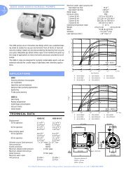
Intended use<br />
Depending on which options have been chosen for it, the<br />
<strong>TPG</strong> <strong>300</strong> can measure total <strong>pressure</strong> from atmosphere to<br />
10 -11 mbar. It can trigger a number of <strong>pressure</strong>-dependent functions<br />
to control <strong>and</strong> monitor vacuum devices <strong>and</strong> processes. The<br />
instructions contained in this document must be strictly followed.<br />
BG 800 <strong>300</strong> BE / A (0105) <strong>TPG</strong> <strong>300</strong> 2
Contents<br />
Product identification 2<br />
Validity 2<br />
Intended use 2<br />
1 Safety 5<br />
1.1 Safety information 5<br />
1.2 Explanation of symbols 5<br />
1.3 General stipulations 6<br />
2 System overview 7<br />
3 Installation 9<br />
3.1 Mains power connection 9<br />
3.2 Plug-in boards 10<br />
3.2.1 Factory configuration 10<br />
3.2.2 Installing / removing plug-in boards 10<br />
3.3 Connecting plug-in boards 10<br />
3.4 Installation in a 19" rack 10<br />
3.5 Use as bench top unit 11<br />
4 Operation 12<br />
4.1 Measuring with the <strong>TPG</strong> <strong>300</strong> 12<br />
4.1.1 Power on procedure 12<br />
4.1.2 Gas type dependence 12<br />
4.1.3 Validity of displayed data 12<br />
4.1.4 Accuracy of measurement 12<br />
4.1.5 Alignment 12<br />
4.2 Front panel 13<br />
4.3 Operating modes 14<br />
4.4 Overview of key entries 15<br />
4.5 »sensor« mode 16<br />
4.5.1 Switching the measuring circuit on / off 16<br />
4.5.2 Measurement range violation 17<br />
4.5.3 Automatic measuring circuit switchover 18<br />
4.5.4 Self-monitoring 18<br />
4.5.5 Plug-in board identification 19<br />
4.6 »set point« mode 20<br />
4.7 »set up« mode 21<br />
4.7.1 Parameter inquiry / modification 21<br />
4.7.2 Parameter overview 21<br />
4.7.3 Default parameters 24<br />
4.7.4 »Switching functions« group 26<br />
4.7.5 »PE measurement underrange control« group 28<br />
4.7.6 »Measurement unit« group 28<br />
4.7.7 »Filter« group 29<br />
4.7.8 »Interface« group 29<br />
4.7.9 »Parameter storage« group 30<br />
4.7.10 »Test programs« group 32<br />
5 Technical data 34<br />
5.1 Mains power connection 34<br />
5.2 Ambiance conditions 34<br />
5.3 Basic unit 34<br />
5.4 Dimensions <strong>and</strong> weight 35<br />
5.5 Plug-in boards 35<br />
BG 800 <strong>300</strong> BE / A (0105) <strong>TPG</strong> <strong>300</strong> 3
6 Error messages, troubleshooting 36<br />
6.1 Error messages 36<br />
6.1.1 Contact setting of the relays in the event of a fault 38<br />
6.2 Troubleshooting 38<br />
6.2.1 Installation problems 38<br />
6.2.2 Operating <strong>and</strong> calibration problems 39<br />
6.2.3 Failures 40<br />
6.2.4 Replacing the apparatus fuses 41<br />
7 Maintenance 42<br />
7.1 Aligning the Pirani measurement circuits 42<br />
7.2 Changing the EPROM 43<br />
8 RS-232-C interface 44<br />
8.1 Installation <strong>and</strong> connection diagram 44<br />
8.2 Data transmission 44<br />
8.2.1 Definitions 44<br />
8.2.2 Flow control 45<br />
8.2.3 Communication protocol 45<br />
8.3 Mnemonics 47<br />
8.3.1 Measured values 48<br />
8.3.2 Switching functions 50<br />
8.3.3 Display 52<br />
8.3.4 Filter time constants 53<br />
8.3.5 Baud rate 54<br />
8.3.6 Storing 54<br />
8.3.7 Auxiliary functions 55<br />
8.3.8 Error messages 56<br />
8.4 Examples of programs 59<br />
9 Accessories, Spare parts 62<br />
9.1 Basic unit <strong>TPG</strong> <strong>300</strong> 62<br />
9.2 Plug-in boards 62<br />
9.3 Mains cables 62<br />
9.4 Gauges 62<br />
9.5 Gauge cables 63<br />
9.6 Accessories for installation in a rack 63<br />
Appendix 64<br />
A: Information main display 64<br />
B: Literature 65<br />
C: Index 66<br />
BG 800 <strong>300</strong> BE / A (0105) <strong>TPG</strong> <strong>300</strong> 4
1 Safety<br />
1.1 Safety information<br />
a) Take into account the relevant safety regulations when installing<br />
the product (→ 9).<br />
b) Take into account the relevant safety regulations when installing<br />
the product <strong>and</strong> putting it into operation.<br />
Pass on the safety information to other users.<br />
1.2 Explanation of symbols<br />
DANGER:<br />
Information on preventing any kind of personal injury or<br />
extensive equipment damage.<br />
CAUTION:<br />
Special information on damage prevention.<br />
NOTE:<br />
Special information on cost-effective use.<br />
Specialists:<br />
This work may only be carried out by persons with suitable<br />
technical training <strong>and</strong> the necessary experience.<br />
Press this key briefly.<br />
= Press these keys simultaneously.<br />
Marking<br />
«....» Display, response<br />
»....« Operating mode, effect<br />
→ See page<br />
→ See document<br />
Tip, re<strong>com</strong>mendation<br />
... please contact your nearest Balzers Service<br />
Center.<br />
1.3 General stipulations<br />
Since the individual electronic <strong>com</strong>ponents are delicate, appropriate<br />
measures must be taken to protect them from static electricity.<br />
Store plug-in modules in antistatic bags or containers.<br />
Damage resulting from disregard of the above warning may lead<br />
to a revocation of the warranty.<br />
BG 800 <strong>300</strong> BE / A (0105) <strong>TPG</strong> <strong>300</strong> 5
Balzers accepts no responsibility nor warranty if the user or third<br />
parties<br />
• utilize the product not according to the defined use<br />
• make any kind of changes (modifications, alterations, etc.) to<br />
the product<br />
• use the product with accessories not listed in the product<br />
documentation.<br />
BG 800 <strong>300</strong> BE / A (0105) <strong>TPG</strong> <strong>300</strong> 6
2 System overview<br />
Information for correct installation of the plug-in boards<br />
→ [3].<br />
A list of all plug-in boards suited for the <strong>TPG</strong> <strong>300</strong> can be found in<br />
section 5.3. For detailed information on the plug-in boards → [3].<br />
Interface plug-in boards<br />
Relay <strong>and</strong><br />
RS-232-C (RS-422)<br />
interface<br />
e.g.<br />
IF <strong>300</strong>A<br />
IF <strong>300</strong>C<br />
Relay <strong>and</strong><br />
RS-232-C interface<br />
e.g.<br />
IF <strong>300</strong>B<br />
BG 800 <strong>300</strong> BE / A (0105) <strong>TPG</strong> <strong>300</strong> 7
Measurement plug-in boards<br />
TPR 010<br />
TPR 017 / TPR 018<br />
Dual Pirani<br />
e.g.<br />
PI <strong>300</strong>D<br />
IKR 050 / IKR 060<br />
IKR 070<br />
Cold cathode<br />
e.g.<br />
PE <strong>300</strong>C9<br />
PE <strong>300</strong>T10<br />
PE <strong>300</strong>DC10<br />
TPR 010<br />
TPR 017 / TPR 018<br />
Pirani / cold cathode<br />
<strong>com</strong>bined<br />
e.g.<br />
CP <strong>300</strong>C9<br />
IKR 050 / IKR 060<br />
IKR 070<br />
BG 800 <strong>300</strong> BE / A (0105) <strong>TPG</strong> <strong>300</strong> 8
3 Installation<br />
If for any reason you can assume that the unit it not safe<br />
to operate, shut it down <strong>and</strong> secure it so that it cannot be<br />
inadvertently turned on again.<br />
You can assume that the unit is not safe to operate when<br />
• it has sustained visible damage<br />
• it no longer functions<br />
• it has been stored for a longer period under unfavorable<br />
conditions<br />
• it has been subjected to severe transport stress<br />
• when the screws of the plug-in boards are loose or<br />
missing.<br />
3.1 Mains power connection<br />
You can connect the <strong>TPG</strong> <strong>300</strong> without voltage adaptation to any<br />
conventional supply system (→ section 5.1).<br />
The power connector may only be plugged into a socket<br />
with a protective ground. Only three-pin mains cables with<br />
a correctly connected protective ground may be used.<br />
This protection must not be nullified by an extension cable<br />
without ground conductor.<br />
To assure continuous grounding protection, connect the<br />
mains power cable before connecting any other cables. In<br />
the same way, disconnect all other cables before disconnecting<br />
the mains power cable.<br />
If the unit is installed in a rack, the mains voltage should<br />
be supplied by <strong>and</strong> turned on via a central distributor.<br />
BG 800 <strong>300</strong> BE / A (0105) <strong>TPG</strong> <strong>300</strong> 9
3.2 Plug-in boards<br />
3.2.1 Factory configuration<br />
In most cases, the <strong>TPG</strong> <strong>300</strong> is supplied ready for operation, (with<br />
the plug-in boards already installed). In addition, in units for<br />
<strong>com</strong>bined measurement of medium <strong>and</strong> high vacuum, the high<br />
vacuum measuring circuit is controlled automatically according to<br />
<strong>pressure</strong>. This is because switching function A <strong>and</strong> / or B is<br />
factory assigned to a medium vacuum measuring circuit<br />
(→ section 4.7.3).<br />
There are two types of configuration:<br />
• Units with CP <strong>300</strong> measurement plug-in board(s)<br />
The cold cathode measuring circuit is controlled by the Pirani<br />
measuring circuit which is on the same measurement plug-in<br />
board.<br />
• Units with PI <strong>300</strong>D <strong>and</strong> PE <strong>300</strong> measurement plug-in boards<br />
The cold cathode measuring circuit is controlled by the Pirani<br />
measuring circuit .<br />
The controlling Pirani <strong>gauge</strong> <strong>and</strong> the controlled cold cathode<br />
<strong>gauge</strong> must both be connected to the same vacuum chamber to<br />
guarantee efficient operation.<br />
No measuring circuit assignment is activated by all other factory<br />
configurations.<br />
3.2.2 Installing / removing plug-in boards<br />
For safety reasons, empty slots should always be covered<br />
with blank plates.<br />
Installing / removing plug-in boards → [3].<br />
3.3 Connecting plug-in boards<br />
→ [3]<br />
3.4 Installation in a 19" rack<br />
If the unit is to be installed in a rack, it must not lower the<br />
protection class of the rack (protection against foreign<br />
objects <strong>and</strong> water) e.g. DIN VDE 0113 regulations for<br />
switch cabinets when in place.<br />
Take into account the ambiance conditions<br />
(→ section 5.2).<br />
BG 800 <strong>300</strong> BE / A (0105) <strong>TPG</strong> <strong>300</strong> 10
The <strong>TPG</strong> <strong>300</strong> can be installed in a 19" rack mount adapter according<br />
to DIN 41 494 . However, it cannot be installed in the old<br />
rack frames constructed according to the Balzers st<strong>and</strong>ard.<br />
Older units (Balzers st<strong>and</strong>ard) are to be installed in the same rack<br />
frame as the <strong>TPG</strong> <strong>300</strong> (DIN), a special adapter must be used<br />
(→ section 9.6).<br />
3.5 Use as bench top unit<br />
Take into account the ambiance conditions<br />
(→ section 5.2).<br />
The ventilation must not be obstructed.<br />
Use the cover <strong>and</strong> the hinged feet (→ 62).<br />
BG 800 <strong>300</strong> BE / A (0105) <strong>TPG</strong> <strong>300</strong> 11
4 Operation<br />
4.1 Measuring with the <strong>TPG</strong> <strong>300</strong><br />
4.1.1 Power on procedure<br />
Before switching the unit on, check that all plug-in boards,<br />
connection cables, <strong>and</strong> <strong>gauge</strong>s are installed correctly<br />
(→ 9) <strong>and</strong> that the technical requirements are satisfied<br />
(→ 34).<br />
If a break in the protective ground occurs inside or outside<br />
the unit or if the protective ground connection is detached,<br />
the unit will be<strong>com</strong>e dangerous. Intentional interruption is<br />
not admissible.<br />
The mains power switch is located on the back panel of the unit.<br />
To switch the unit on, operate the mains power switch (or the<br />
centrally switched mains power distributor in case of installation<br />
into a rack).<br />
After the power has been switched on,<br />
• the unit performs a self-test<br />
• it reactivates the parameters in effect before the unit was<br />
switched off<br />
• all measuring circuits with activated immediate start-up<br />
(→ section 4.7.9) <strong>and</strong> all operational Pirani <strong>gauge</strong>s are<br />
switched on<br />
• the measurement value of the first measuring circuit in operation<br />
is displayed.<br />
4.1.2 Gas type dependence<br />
The measured <strong>pressure</strong> depends on the gas type present. It is<br />
referenced to nitrogen (N2). For other gases please refer to the<br />
characteristic curves shown in the appendix of [3].<br />
4.1.3 Validity of displayed data<br />
If you intend to use the measurement results for control functions,<br />
allow for the time constants of the <strong>gauge</strong>s, possible ignition delays<br />
etc., until valid measurements are displayed (→ [3];<br />
[7] ... [10]).<br />
4.1.4 Accuracy of measurement<br />
A generally applicable statement on the accuracy of the measurement<br />
cannot be made. The type of gas being measured is a<br />
major factor affecting the accuracy, <strong>and</strong> so is the current condition<br />
of the <strong>gauge</strong>.<br />
The accuracy of the <strong>gauge</strong> at any particular moment can only be<br />
assessed by <strong>com</strong>paring the results with a reference unit. Calibration<br />
pumping systems are available for reliable measurements,<br />
particularly for <strong>pressure</strong>s under 10 -4 mbar.<br />
4.1.5 Alignment<br />
Cold cathode measuring circuits are factory aligned <strong>and</strong> require<br />
no recalibration.<br />
Pirani measuring circuits are factory prealigned. For accurate<br />
measurement → [3].<br />
BG 800 <strong>300</strong> BE / A (0105) <strong>TPG</strong> <strong>300</strong> 12
4.2 Front panel<br />
Status display lights<br />
of cold cathode <strong>gauge</strong><br />
Selected sensor display<br />
Error signal<br />
Select sensor for display<br />
of measured data<br />
A1<br />
Operation prompt for <strong>com</strong>bined keys<br />
sensor set point<br />
sensor off<br />
sensor on<br />
set up<br />
PE<br />
Measured value display<br />
Overange/underrange<br />
Identification of plug-in board<br />
Mantissa Exponent<br />
Err 0 10<br />
<strong>TPG</strong> <strong>300</strong><br />
1 2 3 4 A B<br />
step funct group<br />
Bar graph for mantissa (linear indication)<br />
BG 800 <strong>300</strong> BE / A (0105) <strong>TPG</strong> <strong>300</strong> 13<br />
mbar<br />
Unit of measurement<br />
Status of switching function,<br />
lights if status = "ON"<br />
Change to SET POINT mode<br />
Change to SET UP mode
4.3 Operating modes<br />
The <strong>TPG</strong> <strong>300</strong> has three operating modes:<br />
»sensor«<br />
• Pressure measurement<br />
• Selection of the measuring circuit<br />
• Switching <strong>gauge</strong>s on / off<br />
»set point«<br />
• Display of the switching function parameters<br />
»set up«<br />
• Display of the unit parameters<br />
• Modification of the unit parameters<br />
Pow er »on«<br />
BG 800 <strong>300</strong> BE / A (0105) <strong>TPG</strong> <strong>300</strong> 14<br />
»se nso r«<br />
Optional<br />
code input<br />
»se t up «<br />
»se t p o in t«<br />
= =<br />
after approx. 1 minute
4.4 Overview of key entries<br />
»sensor« mode<br />
(Pressure measurement)<br />
Select measuring circuit<br />
Switch on selected <strong>gauge</strong><br />
= =<br />
Switch off selected sensor<br />
Change to »set point« mode<br />
= =<br />
Change to »set up« mode<br />
»set point« mode<br />
(Switching function parameter inquiry)<br />
Select next switching function in<br />
»set point«<br />
Change to »sensor« mode<br />
= =<br />
Change to »set up« mode<br />
»set up« mode<br />
(Parameter inquiry, parameter selection)<br />
Select next group in »set up«<br />
Select next function in »set up« if existing<br />
Modify the selected parameter<br />
Change to »sensor« mode<br />
= In order to avoid unintentional entries, certain operations require <strong>com</strong>bined<br />
key activation (→ operating information on front panel). It is important, however,<br />
that or are not pushed before the other keys,<br />
otherwise the basic function will be executed.<br />
BG 800 <strong>300</strong> BE / A (0105) <strong>TPG</strong> <strong>300</strong> 15
4.5 »sensor« mode<br />
The <strong>TPG</strong> <strong>300</strong> is in »sensor« mode<br />
• after being switched on<br />
• after the key has been pushed<br />
• one minute after the last keystroke in »set point« mode<br />
4.5.1 Switching the measuring circuit on / off<br />
Each individual measuring circuit can be<br />
manually switched on or off (after entering<br />
the code with <strong>and</strong> )<br />
Manual on/off-switching has priority over the<br />
automatic control.<br />
Switch on cold cathode <strong>gauge</strong>s at<br />
<strong>pressure</strong>s
4.5.2 Measurement range violation<br />
If the measured value is outside the measuring<br />
range of the measuring circuit, this will<br />
be indicated if the corresponding measuring<br />
circuit is selected.<br />
If the cold cathode measuring circuit is controlled<br />
by another measuring circuit, the display<br />
changes over automatically.<br />
If the upper measuring range limit is<br />
exceeded, the cold cathode <strong>gauge</strong><br />
can be<strong>com</strong>e contaminated if it remains<br />
switched on.<br />
If the under range control is switched off (→<br />
section 4.7.5) the system cannot distinguish<br />
between a <strong>gauge</strong> failure, cable interruption<br />
<strong>and</strong> underrange of a cold cathode measuring<br />
circuit. «ur» is displayed in all cases.<br />
Measuring circuit on Measuring circuit off<br />
Overrange<br />
B1 PE<br />
0 10<br />
BG 800 <strong>300</strong> BE / A (0105) <strong>TPG</strong> <strong>300</strong> 17<br />
mbar<br />
1 2 3 4 A B<br />
Overrange: «or» <strong>and</strong> exponent indicating<br />
the range limit<br />
Underrange<br />
B1 PE<br />
0 10<br />
mbar<br />
1 2 3 4 A B<br />
Underrange: «ur» <strong>and</strong> exponent indicating<br />
the range limit
4.5.3 Automatic measuring circuit switchover<br />
If a measuring circuit is controlled by another<br />
measuring circuit <strong>and</strong> either one is<br />
selected, the display automatically changes<br />
over<br />
• when the measured value drops below<br />
the lower threshold<br />
• when the measured value exceeds the<br />
upper threshold.<br />
4.5.4 Self-monitoring<br />
If the cold cathode measuring circuit is selfmonitored,<br />
it automatically switches off<br />
• when the measured value exceeds the<br />
upper threshold.<br />
The measuring circuit must be restarted<br />
manually. Restarting can be prevented by<br />
another measuring circuit (e.g. Pirani).<br />
Measured value or e.g.<br />
B1<br />
0 10<br />
BG 800 <strong>300</strong> BE / A (0105) <strong>TPG</strong> <strong>300</strong> 18<br />
1 2 3 4 A B<br />
Automatic control: «Au», cold cathode measuring circuit waits for the fulfillment of the<br />
power on condition by the Pirani measuring circuit.<br />
Measured value or e.g.<br />
B1<br />
0 10<br />
1 2 3 4 A B
4.5.5 Plug-in board identification<br />
When the measuring circuit is switched off, its identification is displayed (→ section 4.5.1).<br />
Main display Meaning<br />
«Au 9» Cold cathode measuring circuit 5×10<br />
«Au 10»<br />
«Au 11»<br />
-9 mbar<br />
automatic operation<br />
Cold cathode measuring circuit 1×10 -10 mbar<br />
automatic operation<br />
Cold cathode measuring circuit 10 -11 mbar<br />
automatic operation<br />
«PE 9» Cold cathode measuring circuit 5×10<br />
«PE 10»<br />
«PE 11»<br />
-9 mbar<br />
Cold cathode measuring circuit 1×10 -10 mbar<br />
Cold cathode measuring circuit 10 -11 mbar<br />
«PI » Pirani measuring circuit<br />
«PI l » Pirani measuring circuit for long cables<br />
«PI n» Pirani measuring circuit for nickel filament<br />
«PI ln» Pirani measuring circuit for long cables <strong>and</strong> nickel<br />
filament<br />
BG 800 <strong>300</strong> BE / A (0105) <strong>TPG</strong> <strong>300</strong> 19
4.6 »set point« mode<br />
Selecting the »set point« mode<br />
• Push the key (only possible in »sensor« mode<br />
• The bar graph display extinguishes<br />
Assignment of switching function to measuring<br />
circuit<br />
With you can read cyclically the<br />
Threshold<br />
threshold values <strong>and</strong> assignments of the<br />
l<br />
switching functions. A1<br />
mbar 1 2 3 4 A B<br />
0 10<br />
Quitting the »set point« mode<br />
• Select another mode or<br />
• Wait a minute after the last key was pushed. The <strong>TPG</strong> <strong>300</strong> then<br />
switches automatically back to »sensor« mode (measuring<br />
mode)<br />
The function of the measuring circuits is not influenced.<br />
The current status of the switching functions is not displayed, but they work nevertheless.<br />
With you can go directly to the »select threshold« function of the »set up« mode<br />
to change the displayed threshold value.<br />
BG 800 <strong>300</strong> BE / A (0105) <strong>TPG</strong> <strong>300</strong> 20
4.7 »set up« mode<br />
Selecting the »set up« mode<br />
• Simultaneously push the <strong>and</strong> keys<br />
• Enter the code with <strong>and</strong> if required<br />
• The bar graph display extinguishes<br />
Quitting the »set up« mode<br />
• Push the key<br />
4.7.1 Parameter inquiry / modification<br />
The parameters are organized in two levels (groups <strong>and</strong><br />
functions ).<br />
Select the parameter to be displayed in the »set up« mode<br />
• Push the or key<br />
• Modify the parameter by pushing the key<br />
4.7.2 Parameter overview<br />
Comments to the following table:<br />
• Groups, functions or parameters which do not exist because<br />
of the unit configuration will be bypassed.<br />
• Inputs in groups, functions <strong>and</strong> parameters always work cyclically.<br />
In case of error, simply go ahead up to the right spot<br />
again.<br />
• The pictures shown in the table correspond to the first function<br />
of each group.<br />
BG 800 <strong>300</strong> BE / A (0105) <strong>TPG</strong> <strong>300</strong> 21
Group Function Parameter values <br />
Switching functions Switching function selection<br />
1 2 3 4 A B Threshold selection<br />
1, 2, 3, 4, A, B<br />
lower, upper<br />
PE measuring circuit<br />
underrange control<br />
Measurement unit<br />
mbar<br />
Torr<br />
Pa<br />
Threshold 1st digit mantissa 1 ... 9<br />
Threshold 2nd digit mantissa 0 ... 9<br />
Threshold exponent –11 ... +3<br />
Measuring circuit assignment A1, A2, B1, B2, – (none)<br />
Control 0 (disabled)<br />
1 (enabled)<br />
Measurement unit selection<br />
mbar, Torr, Pa<br />
Filter Filter assignment<br />
A1<br />
A2<br />
Filter time constant<br />
A1, A2, B1, B2<br />
1 (fast)<br />
2 (medium)<br />
B1<br />
3 (slow)<br />
B2<br />
BG 800 <strong>300</strong> BE / A (0105) <strong>TPG</strong> <strong>300</strong> 22
Interface Baud rate 3 (<strong>300</strong>)<br />
1 (1200)<br />
2 (2400)<br />
4 (4800)<br />
9 (9600)<br />
Parameter storage Parameter program selection u (user)<br />
Code 00 0 ... 99 19<br />
H (hotstart)<br />
Code 00 0 ... 99 19<br />
d (default)<br />
Storage (save) Time for consideration<br />
Test programs Test program selection dI (display)<br />
rA (RAM)<br />
EP (EPROM)<br />
EE (EEPROM)<br />
Ad (A/D converter)<br />
Channel selection A0 .. A7<br />
Io (keys)<br />
rS (interface)<br />
Pn (program number)<br />
Test t (test start)<br />
BG 800 <strong>300</strong> BE / A (0105) <strong>TPG</strong> <strong>300</strong> 23
4.7.3 Default parameters<br />
The default parameters are summarized in the following table. In<br />
the ‘User’ column, you can enter your own parameter set.<br />
Parameter Default User User<br />
Lower threshold Switching function 1 1.0 × 10 -11 mbar<br />
Switching function 2 1.0 × 10 -11 mbar<br />
Switching function 3 1.0 × 10 -11 mbar<br />
Switching function 4 1.0 × 10 -11 mbar<br />
Switching function A 6.0 × 10 -3 mbar<br />
Switching function B 6.0 × 10 -3 mbar<br />
Upper threshold Switching function 1 9.0 × 10 -11 mbar<br />
Switching function 2 9.0 × 10 -11 mbar<br />
Switching function 3 9.0 × 10 -11 mbar<br />
Switching function 4 9.0 × 10 -11 mbar<br />
Switching function A 8.0 × 10 -3 mbar<br />
Switching function B 8.0 × 10 -3 mbar<br />
Measuring circuit assignment<br />
Switching function 1 – (none)<br />
Switching function 2 – (none)<br />
Switching function 3 – (none)<br />
Switching function 4 – (none)<br />
Switching function A – (none) *) *)<br />
Switching function B – (none) *) *)<br />
BG 800 <strong>300</strong> BE / A (0105) <strong>TPG</strong> <strong>300</strong> 24
Parameter Default User User<br />
PE Underrange control 0 (disabled)<br />
Unit of measurement mbar<br />
Filter time constant Measuring circuit A1 2 (medium)<br />
Measuring circuit A2 2 (medium)<br />
Measuring circuit B1 2 (medium)<br />
Measuring circuit B2 2 (medium)<br />
Baud rate 9 (9600)<br />
Immediate start-up Measuring circuit A1 - (no)<br />
Measuring circuit A2 - (no)<br />
Measuring circuit B1 - (no)<br />
Measuring circuit B2 - (no)<br />
Code 00 0 (unlocked)<br />
*)<br />
For measuring circuit assignments configured at the<br />
factory as user parameters for units with medium <strong>and</strong><br />
high vacuum measuring circuits that are ready for operation<br />
→ section 3.2.1.<br />
BG 800 <strong>300</strong> BE / A (0105) <strong>TPG</strong> <strong>300</strong> 25
4.7.4 »Switching functions« group<br />
a) »Switching function selection« function<br />
Switching functions 1 to 4 affect the relays of an interface<br />
plug-in board (accessory). A <strong>and</strong> B can control the on/off<br />
switching of the cold cathode <strong>gauge</strong> heads.<br />
Switching<br />
function<br />
1<br />
2<br />
3<br />
4<br />
A<br />
B<br />
0 10<br />
Affects<br />
mbar<br />
1 2 3 4 A B<br />
Interface plug-in board relay 1<br />
Interface plug-in board relay 2<br />
Interface plug-in board relay 3<br />
Interface plug-in board relay 4<br />
Cold cathode measuring circuit(s) in slot A<br />
Cold cathode measuring circuit(s) in slot B<br />
b) »Threshold selection« function<br />
Defining an upper <strong>and</strong> a lower threshold defines a hysteresis<br />
for each switching function.<br />
0 10<br />
BG 800 <strong>300</strong> BE / A (0105) <strong>TPG</strong> <strong>300</strong> 26<br />
mbar<br />
1 2 3 4 A B<br />
When the <strong>pressure</strong> is dropping, the status changes to »on« at<br />
the lower threshold <strong>and</strong> to »off« at the upper threshold.<br />
Status of switching function<br />
OFF<br />
ON<br />
lower upper<br />
threshold value<br />
Pressure p<br />
Hysteresis ∆p is a minimum of 10% of the lower<br />
threshold. This prevents unstable states.<br />
If you set the upper threshold too low, the minimum hysteresis<br />
will go into effect automatically.
c) »Threshold setting« function<br />
0 10<br />
<br />
mbar<br />
1 2 3 4 A B<br />
<br />
<br />
Modifications only be<strong>com</strong>e effective when the switching<br />
function, group or operating mode is changed.<br />
d) »Measuring circuit assignment« function<br />
Any of the switching points can be assigned to any of the<br />
measuring channels.<br />
Changing the assignment can trigger a change in the<br />
switching function status.<br />
BG 800 <strong>300</strong> BE / A (0105) <strong>TPG</strong> <strong>300</strong> 27<br />
A1<br />
A2<br />
B1<br />
B2<br />
0 10<br />
mbar<br />
1 2 3 4 A B<br />
The cycle depends on the plug-in boards installed.<br />
Available measuring circuits are indicated by an LED.<br />
The upper <strong>and</strong> lower thresholds of switching functions<br />
1 ... 4 cannot be assigned to different measuring circuits.<br />
The last entry made applies.<br />
The upper <strong>and</strong> lower thresholds of switching functions A<br />
<strong>and</strong> B can be assigned to different measuring circuits<br />
(→ section 4.5.4).<br />
The LED for the assigned measuring circuit flashes.<br />
It is possible to leave a switching function unassigned (no<br />
measuring circuit LED will flash). The switching function is<br />
ineffective.<br />
Modifications only be<strong>com</strong>e effective when the switching<br />
function, group or operating mode is changed.
4.7.5 »PE measurement underrange control«<br />
group<br />
The behavior of switching functions assigned to the cold cathode<br />
measuring circuit (PE) can be adjusted when underrange occurs<br />
(→ section 4.5.2) (except in the case of self assignment).<br />
0 10<br />
Display Meaning<br />
1 2 3 4 A B<br />
Pu 0 »UnderRng« is interpreted as valid measured<br />
value; the switching function remains »on«<br />
Pu 1 »UnderRng« is interpreted as an error; the<br />
switching function changes to »off«. The switching<br />
function does not change to »on« until the<br />
measured value has remained within the<br />
measurement range of the cold cathode measuring<br />
circuit for at least 10 seconds.<br />
Cold cathode measuring circuits for 10 -11 mbar sometimes<br />
require more than 10 seconds for the transition<br />
«OverRng» «UnderRng» <strong>and</strong> thus lead the switching<br />
function being »on« for a short time.<br />
4.7.6 »Measurement unit« group<br />
Select the desired measurement unit:<br />
0 10<br />
BG 800 <strong>300</strong> BE / A (0105) <strong>TPG</strong> <strong>300</strong> 28<br />
mbar<br />
Torr<br />
Pa<br />
1 2 3 4 A B<br />
The modification is made immediately.<br />
The threshold values for the switching functions are<br />
adapted automatically.
4.7.7 »Filter« group<br />
In the event of fast varying measurement signals, the measured<br />
values can be filtered to stabilize both, the display <strong>and</strong> the<br />
switching functions.<br />
a) »Filter assignment« function<br />
You can set the filter separately for each individual measuring<br />
circuit.<br />
A1<br />
A2<br />
B1<br />
B2<br />
0 10<br />
1 2 3 4 A B<br />
The cycle depends on the plug-in boards installed.<br />
b) »Filter time constant« function<br />
Three filter time constants are available.<br />
A1<br />
In the case of signal fluctuations, a faster filter can<br />
cause 'fluttering' of switching functions.<br />
0 10<br />
1 2 3 4 A B<br />
Display Filter Time constant<br />
BG 800 <strong>300</strong> BE / A (0105) <strong>TPG</strong> <strong>300</strong> 29<br />
FI 1<br />
FI 2<br />
FI 3<br />
fast<br />
medium (default)<br />
slow<br />
16 ms<br />
160 ms<br />
1.6 s<br />
Any modification is made immediately.<br />
The analog outputs are not affected.<br />
4.7.8 »Interface« group<br />
a) »Baud rate« function<br />
0 10<br />
Display Baud rate<br />
bd 3<br />
bd 1<br />
bd 2<br />
bd 4<br />
bd 9<br />
<strong>300</strong><br />
1200<br />
2400<br />
4800<br />
9600 (default)<br />
1 2 3 4 A B<br />
The baud rates for the <strong>TPG</strong> <strong>300</strong> <strong>and</strong> any interfaced<br />
<strong>com</strong>puter must be the same.
4.7.9 »Parameter storage« group<br />
The stored parameters are activated when the <strong>TPG</strong> <strong>300</strong> is<br />
switched on. If no parameters have been stored, the unit defaults<br />
to the st<strong>and</strong>ard parameter set given in section 4.7.3.<br />
a) »Parameter set« function<br />
0 10<br />
1 2 3 4 A B<br />
You can either select your own set of parameters (user) or the<br />
default set to be saved.<br />
Display Meaning<br />
SA u<br />
SA H<br />
SA d<br />
Save user parameters (SAve user)<br />
Save user parameters with immediate start-up<br />
(SAve Hotstart)<br />
Save default (factory set) parameters(SAve defaults)<br />
By activating the immediate start-up, a measuring circuit<br />
can be automatically re-enabled after a power failure. This<br />
is particularly useful in the case of self-monitoring.<br />
The immediate start-up is jointly activated for all measuring<br />
circuits. The measuring circuit must however be<br />
switched on during storage.<br />
At «SA u» <strong>and</strong> «SA H», the unit can be locked by a code<br />
number (→ following section).<br />
b) »Save« function<br />
Saving the default parameters has the following effects:<br />
• The switching function assignments are lost.<br />
• The relays are de-energized, i.e. the switching<br />
functions change to »off«.<br />
• Communication with a <strong>com</strong>puter may no longer be<br />
possible.<br />
0 10<br />
BG 800 <strong>300</strong> BE / A (0105) <strong>TPG</strong> <strong>300</strong> 30<br />
1 2 3 4 A B
0 10<br />
<br />
hold down<br />
0 10<br />
Time for consideration<br />
0 10<br />
Parameter stored<br />
If «SA u» or «SA H» is selected (store user parameters),<br />
you will be asked to enter a code before storage takes<br />
place. This is a protection against inadvertent or unauthorized<br />
manipulations on the operating states of the sensors<br />
or the parameters. In this mode the unit may be unlocked<br />
in the same way.<br />
If you do not wish to modify the lock, then push <br />
three times.<br />
Pushing until the bar graph is <strong>com</strong>pletely dark<br />
causes the parameters to be stored. When the storage<br />
process is finished, the bar graph lights again.<br />
After storing, your unit will work with the newly stored parameter<br />
set.<br />
If you release before the bar graph is <strong>com</strong>pletely<br />
dark (time for consideration), nothing will be stored.<br />
Code 0 <strong>TPG</strong> can be operated without entering a<br />
code<br />
Code 1–1998 <strong>TPG</strong> can be operated when a corresponding<br />
code is entered<br />
Code 1999 <strong>TPG</strong> can be operated only when this particular<br />
code is entered (code cannot be<br />
modified)<br />
BG 800 <strong>300</strong> BE / A (0105) <strong>TPG</strong> <strong>300</strong> 31
4.7.10 »Test programs« group<br />
Tests marked with * are carried out automatically when the<br />
<strong>TPG</strong> <strong>300</strong> is switched on. You can also run all tests during operation.<br />
They do not influence measurements <strong>and</strong> switching functions.<br />
a) »Test program selection« function<br />
0 10<br />
1 2 3 4 A B<br />
Display Tested part<br />
dI *<br />
rA *<br />
EP *<br />
EE *<br />
Ad<br />
A0<br />
A1<br />
A2<br />
A3<br />
A4<br />
A5<br />
A6<br />
A7<br />
Io *<br />
rS<br />
Pn<br />
Display<br />
RAM<br />
EPROM<br />
EEPROM<br />
A/D converter<br />
Channel 0<br />
Channel 1<br />
Channel 2<br />
Channel 3<br />
Channel 4<br />
Channel 5<br />
Channel 6<br />
Channel 7<br />
Keys<br />
RS-232-C interface<br />
Program number<br />
The display test lights first all LEDs together <strong>and</strong> then individually.<br />
The RAM routine tests the two kByte of the RAM.<br />
A check sum is formed <strong>and</strong> controlled in both, the<br />
EPROM <strong>and</strong> EEPROM test.<br />
You must enter the channel (0 ... 7) when running the A/D<br />
converter test. A/D input voltage = display × 5 mV.<br />
«Io» checks whether any key contact is stuck.<br />
«rS» echoes HOST characters <strong>com</strong>ing from the host. It<br />
displays them in the Hex format in the mantissa field <strong>and</strong><br />
their number in the exponent field.<br />
BG 800 <strong>300</strong> BE / A (0105) <strong>TPG</strong> <strong>300</strong> 32
«Pn» gives a read-out of your program number.<br />
b) »Test« function<br />
Start the chosen routine with .<br />
Any errors found are reported (→ 36).<br />
0 10<br />
1 2 3 4 A B<br />
You can always return to »test« by pushing the <br />
key.<br />
The «dI», «Ad», «rS», <strong>and</strong> «Pn» routines run continually<br />
<strong>and</strong> must be stopped by pushing or . All<br />
the other tests run through once. When they are finished,<br />
a line appears in the exponent display.<br />
You can stop the «dI» by pushing <strong>and</strong> start it<br />
again as often as you like.<br />
c) »Program version« function<br />
BG 509 780 -F<br />
Modification index<br />
You can read out the program version of your unit by conducting<br />
the corresponding test (Pn).<br />
A program with a higher modification index will eventually provide<br />
additional services.<br />
This operating manual is not valid for a more recent program<br />
number.<br />
BG 800 <strong>300</strong> BE / A (0105) <strong>TPG</strong> <strong>300</strong> 33
5 Technical data<br />
5.1 Mains power connection<br />
Voltage<br />
Frequency<br />
Power consumption<br />
Fuses<br />
5.2 Ambiance conditions<br />
100 ... 240 VAC ±10%<br />
50 ... 60 Hz<br />
60 VA<br />
F1, F2: 1,25 AT, 250 V, Ø5×20 mm<br />
The following data apply to all assemblies in the <strong>TPG</strong> <strong>300</strong> unless<br />
otherwise indicated.<br />
Admissible temperature<br />
Storage<br />
Operation<br />
–40 °C ... +65 °C<br />
rack installation + 5 °C ... +50 °C<br />
bench-top unit + 5 °C ... +40 °C<br />
+ 5 °C ... +50 °C (with cover / hinged<br />
feet)<br />
Relative humidity max. 80% at temperatures up to<br />
+31 °C decreasing to 50% at +40 °C<br />
Use indoors only<br />
Height up to 2000 m<br />
Protection IP 40<br />
Safety EN 61010: 93 (IEC 1010: 90 + A1: 92)<br />
Class I, Pollution degree 2<br />
EMC Emission EN 50081 -1: 92<br />
Immunity EN 50082 -2: 95<br />
5.3 Basic unit<br />
Measurement range depending on the measurement plug-in<br />
boards used→ [3]<br />
Length of <strong>gauge</strong> cable depending on the measurement plug-in<br />
boards used → [3]<br />
Measurement rate 100 per s<br />
Display rate<br />
Filter time constant<br />
5 per s<br />
FI 1 (fast)<br />
approx. 16 ms<br />
FI 2 (medium) approx. 160 ms<br />
FI 3 (slow)<br />
approx. 1.6 s<br />
Displays<br />
Measured value digital 15 mm 7 segment display<br />
Mantissa<br />
2 position<br />
Exponent<br />
1½ position<br />
Measured value analog 20 position LED bar<br />
Status 17 LEDs<br />
Error message 1 LED, red<br />
BG 800 <strong>300</strong> BE / A (0105) <strong>TPG</strong> <strong>300</strong> 34
Slots for<br />
measurement plug-in<br />
boards<br />
interface plug-in<br />
boards<br />
2 (slots A <strong>and</strong> B)<br />
1 (slot C)<br />
Compatible measurement<br />
plug-in boards<br />
Pirani PI <strong>300</strong>D, PI <strong>300</strong>DN<br />
PI <strong>300</strong>DL, PI <strong>300</strong>DLN<br />
Cold cathode PE <strong>300</strong>C9, PE <strong>300</strong>C10<br />
PE <strong>300</strong>T10, PE <strong>300</strong>T11<br />
PE <strong>300</strong>DC9, PE <strong>300</strong>DT9<br />
Combined Pirani /<br />
cold cathode<br />
CP <strong>300</strong>C9, CP <strong>300</strong>C9N<br />
CP <strong>300</strong>T9L, CP <strong>300</strong>T9LN<br />
CP <strong>300</strong>C10, CP <strong>300</strong>C10N<br />
CP <strong>300</strong>T10, CP <strong>300</strong>T10N<br />
CP <strong>300</strong>T10L, CP <strong>300</strong>T10LN<br />
CP <strong>300</strong>T11, CP <strong>300</strong>T11N<br />
CP <strong>300</strong>T11L, CP <strong>300</strong>T11LN<br />
Compatible interface<br />
plug-in boards IF <strong>300</strong>A, IF <strong>300</strong>B, IF <strong>300</strong>C<br />
5.4 Dimensions <strong>and</strong> weight<br />
Dimensions<br />
sensor set point<br />
step funct group<br />
sensor off<br />
sensor on<br />
set up<br />
BG 800 <strong>300</strong> BE / A (0105) <strong>TPG</strong> <strong>300</strong> 35<br />
128,4<br />
A1 PE<br />
A2<br />
B1 PE<br />
B2<br />
141,9 235 2,5<br />
Err 0 10<br />
<strong>TPG</strong> <strong>300</strong><br />
mbar 1 2 3 4 A B<br />
Torr<br />
Pa<br />
Weight 1.35 kg (without plug-in boards)<br />
5.5 Plug-in boards<br />
Technical data of the <strong>com</strong>patible measurement <strong>and</strong> interface<br />
plug-in boards → [3].<br />
Before you connect any external elements, check that<br />
they are <strong>com</strong>patible with the technical data.
6 Error messages, troubleshooting<br />
Manipulations inside the unit that are not described in this<br />
operating manual may only be performed by a Balzers<br />
Service Center.<br />
6.1 Error messages<br />
An error message is<br />
indicated by a lighting<br />
or flashing «Err»<br />
LED.<br />
A2<br />
Err 0 10<br />
mbar<br />
1 2 3 4 A B<br />
Display Possible cause Correction<br />
«dt» 3)<br />
Watch Dog timer – overflow due to strong external influence<br />
(electromagnetic)<br />
<br />
If this error occurs frequently, replace the basic unit<br />
«EE» 3)<br />
Error during parameter reading Store default or user parameters(→ section 4.7.9)<br />
«EP» 3)<br />
«Id» 3)<br />
«IF» 3)<br />
EEPROM defective<br />
EPROM defective<br />
Operating system overloaded<br />
<br />
Interface plug-in board in slot A or B Put the interface plug-in board into slot C 2)<br />
BG 800 <strong>300</strong> BE / A (0105) <strong>TPG</strong> <strong>300</strong> 36
Display Possible cause Correction<br />
«Io» 3)<br />
«rA» 3)<br />
«rS» 3)<br />
«SE» 4)<br />
«So» 3)<br />
Key pushed Release key<br />
Key stuck<br />
RAM defective<br />
Transmission or programming error Correct interface parameter or cable, program<br />
Interface defective Replace interface plug-in board 2)<br />
TPR <strong>gauge</strong> not connected Connect <strong>gauge</strong><br />
Break in TPR cable Replace cable<br />
TRR <strong>gauge</strong> defective Replace <strong>gauge</strong><br />
Stack overflow<br />
2) Please read the information in section 3.2.2 before performing<br />
any manipulations on the plug-in boards.<br />
3) Fatal error<br />
4)<br />
Fault in measuring circuit (LED of the corresponding measurement<br />
circuit flashes)<br />
<br />
BG 800 <strong>300</strong> BE / A (0105) <strong>TPG</strong> <strong>300</strong> 37
6.1.1 Contact setting of the relays in the event of a<br />
fault<br />
The relays on the IF <strong>300</strong>A, IF <strong>300</strong>B, <strong>and</strong> IF <strong>300</strong>C plug-in boards<br />
behave as follows when a fault occurs:<br />
A contact 1...4 (switching function) is de-energized in the event of:<br />
• a fault in the assigned measuring circuit<br />
• a fatal error<br />
Contact 5 (Error status) is de-energized in the event of:<br />
• a fault in a measuring circuit<br />
• a fatal error<br />
Additional information on relay contact states → [3].<br />
6.2 Troubleshooting<br />
6.2.1 Installation problems<br />
Problem Possible cause Correction<br />
The control unit cannot be installed into the<br />
rack<br />
Old rack system Use a rack mount adapter according to<br />
DIN 41 494 (→ section 9.6)<br />
BG 800 <strong>300</strong> BE / A (0105) <strong>TPG</strong> <strong>300</strong> 38
6.2.2 Operating <strong>and</strong> calibration problems<br />
Problem Possible cause Correction<br />
No display appears when the unit is<br />
switched on<br />
Unit switched off for too short a period<br />
of time<br />
After switching the unit off, wait approx. 10 seconds<br />
before restarting<br />
Pressure display unstable Filter time constant too low Increase the filtering (→ section 4.7.7)<br />
Switching functions (relays) flutter Hysteresis too small Modify the threshold values (→ section 4.7.4)<br />
Increase the filtering (→ section 4.7.7)<br />
Pirani <strong>pressure</strong> display too high Pirani <strong>gauge</strong> contaminated Calibrate the measuring circuit<br />
Pirani measurement circuit cannot be calibrated<br />
Combination measurement plug-in<br />
board / <strong>gauge</strong> cable / <strong>gauge</strong> is not<br />
<strong>com</strong>patible<br />
Cold cathode <strong>pressure</strong> display too high Contaminated or moist connector insulation<br />
Clean the <strong>gauge</strong> (→ [4] ... [6])<br />
Replace the <strong>gauge</strong><br />
Select correct <strong>com</strong>bination (→ [3])<br />
Pirani <strong>gauge</strong> severely contaminated Clean the <strong>gauge</strong> (→ [4] ... [6])<br />
Replace the <strong>gauge</strong><br />
Clean or replace connector<br />
Humidity ( leak current) Keep humidity low, keep the unit switched on<br />
Cold cathode <strong>pressure</strong> display too low Cold cathode <strong>gauge</strong> contaminated Clean the <strong>gauge</strong> (→ [7] ... [10])<br />
«no P» is displayed No plug-in board has been installed Install the appropriate plug-in board 2)<br />
In<strong>com</strong>prehensible display Plug-in board not screwed down Tighten the screws<br />
Contacts contaminated / bent Clean / carefully straighten contacts 2)<br />
BG 800 <strong>300</strong> BE / A (0105) <strong>TPG</strong> <strong>300</strong> 39
Problem Possible cause Correction<br />
Unit cannot be locked Code 99 19 activated 1. Pull the measurement plug-in boards approx.<br />
1 cm out of the slots A <strong>and</strong> B 2)<br />
2. Change the code in »set up« mode<br />
3. Reinstall the measurement plug-in boards 2)<br />
Code forgotten --- 1. Pull the measurement plug-in boards approx.<br />
1 cm out of the slots A <strong>and</strong> B 2)<br />
2) Please read the instructions in 3.2.2 before performing any manipulations on the plug-in boards.<br />
6.2.3 Failures<br />
Problem Possible cause Correction<br />
No display appears when the unit is<br />
switched on<br />
No mains power Check mains<br />
Individual LEDs, or segments of the 7segment<br />
or bar graph display do not light<br />
2. Select the code in »set up« mode<br />
3. Read out the code<br />
4. Reinstall the measurement plug-in boards 2)<br />
Fuse defective Replace fuse (→ section 6.2.4)<br />
Display / microprocessor defective<br />
BG 800 <strong>300</strong> BE / A (0105) <strong>TPG</strong> <strong>300</strong> 40
6.2.4 Replacing the apparatus fuses<br />
The fuses are located inside the unit on the power supply board.<br />
Procedure<br />
• Switch the unit off <strong>and</strong> wait one minute<br />
• Remove all cables (mains last)<br />
• Unscrew the back panel<br />
• Pull out the back panel together with the plug-in boards<br />
just far enough to make the fuses accessible<br />
• Replace the fuses<br />
Make sure to replace fuses with fuses of the re<strong>com</strong>mended<br />
type <strong>and</strong> nominal current strength (→ 62). It<br />
is not permissible to use mended fuses or to short circuit<br />
the fuse holder.<br />
• Reassemble in reverse order<br />
Put the screw lockings in place again <strong>and</strong><br />
tighten the screws!<br />
If the fuses blow again.<br />
BG 800 <strong>300</strong> BE / A (0105) <strong>TPG</strong> <strong>300</strong> 41
7 Maintenance<br />
The total <strong>pressure</strong> <strong>gauge</strong> <strong>and</strong> <strong>controller</strong> <strong>TPG</strong> <strong>300</strong> requires no<br />
maintenance. For maintenance of the <strong>gauge</strong>s, refer to the respective<br />
documents [4] ... [10].<br />
Turn the unit off <strong>and</strong> remove all cables (the mains cable<br />
last) before doing any of the work described below.<br />
For cleaning the outside of the unit, a slightly humid cloth will<br />
usually do. Do not use under any circumstances an aggressive or<br />
scouring leaning agent. No water must get into the unit! Before<br />
putting the unit into operation again, allow it to dry thoroughly.<br />
In a very dusty environment, the dust inside the unit<br />
should be periodically removed. Carefully remove the dust<br />
with dry <strong>com</strong>pressed air.<br />
7.1 Aligning the Pirani measurement circuits<br />
→ [3]<br />
BG 800 <strong>300</strong> BE / A (0105) <strong>TPG</strong> <strong>300</strong> 42
7.2 Changing the EPROM<br />
For updated firmware versions, the EPROM must be changed.<br />
Please contact your nearest Balzers partner to inquire about the<br />
most recent update.<br />
Disconnect all cables from the unit before changing the<br />
EPROM.<br />
Protect the EPROM <strong>and</strong> the electronics of the <strong>TPG</strong> <strong>300</strong><br />
from static electricity.<br />
Procedure<br />
1. Store default values (→ 30).<br />
2. Switch the unit off <strong>and</strong> wait one minute.<br />
3. Detach all cables from the unit (mains cable last).<br />
4. Unscrew the front panel assembly <strong>and</strong> remove it (fig. 1).<br />
5. Carefully remove the old EPROM.<br />
6. Install the EPROM (correct polarity: fig. 2).<br />
7. Carefully slide the front panel assembly back, plug it in, <strong>and</strong><br />
screw it down.<br />
8. Re-attach all cables (mains cable first).<br />
9. Switch the unit on again.<br />
BG 800 <strong>300</strong> BE / A (0105) <strong>TPG</strong> <strong>300</strong> 43<br />
Fig. 1<br />
Fig.2<br />
Pin 1
8 RS-232-C interface<br />
The serial interface allows <strong>com</strong>munication between the <strong>TPG</strong> <strong>300</strong><br />
<strong>and</strong> a <strong>com</strong>puter. A terminal can also be connected for test purposes.<br />
8.1 Installation <strong>and</strong> connection diagram<br />
→ [3]<br />
8.2 Data transmission<br />
Information is exchanged bi-derectionally, i.e. the data <strong>and</strong><br />
control <strong>com</strong>m<strong>and</strong>s can flow in either direction.<br />
8.2.1 Definitions<br />
The following abbreviations <strong>and</strong> symbols are used:<br />
Symbol Meaning<br />
HOST Computer or terminal<br />
[...] Non m<strong>and</strong>atory elements<br />
ASCII American St<strong>and</strong>ard Code for Information Interchange<br />
ASCII<br />
Dec. Hex.<br />
END OF TEXT<br />
(CTRL C)<br />
Reset of interface 3 03<br />
CARRIAGE<br />
RETURN<br />
Carriage return 13 0D<br />
LINE FEED Line feed 10 0A<br />
ENQUIRY Request to send 5 05<br />
ACKNOWLEDGE Positive confirmation<br />
NEGATIVE<br />
ACKNOWLEDGE<br />
Negative confirmation<br />
"Send": Transfer from HOST to <strong>TPG</strong> <strong>300</strong><br />
"Receive": Transfer from <strong>TPG</strong> <strong>300</strong> to HOST<br />
6 06<br />
21 15<br />
BG 800 <strong>300</strong> BE / A (0105) <strong>TPG</strong> <strong>300</strong> 44
8.2.2 Flow control<br />
After each ASCII string the HOST must wait for a confirmation<br />
( or ) to ensure that the input buffer is<br />
empty.<br />
The input buffer of the HOST must have a capacity of at least 32<br />
bytes.<br />
8.2.3 Communication protocol<br />
Send format<br />
Messages are transmitted to the <strong>TPG</strong> <strong>300</strong> as ASCII strings in the<br />
form of mnemonics <strong>and</strong> parameters. All mnemonics <strong>com</strong>prise<br />
three ASCII characters.<br />
Spaces are ignored. (CTRL C) clears the input buffer in<br />
the <strong>TPG</strong> <strong>300</strong>.<br />
The input is terminated by or or ("end of<br />
message"), <strong>and</strong> evaluation in the <strong>TPG</strong> <strong>300</strong> is subsequently<br />
started.<br />
The tables in section 8.3 are applicable to the mnemonics <strong>and</strong><br />
parameters. The maximum number of digits, the data format <strong>and</strong><br />
admissible value ranges are also specified there.<br />
Send protocol<br />
HOST <strong>TPG</strong> <strong>300</strong> Explanation<br />
Mnemonics [<strong>and</strong> parameters] Receives message with<br />
[] "end of message"<br />
Positive acknowledgment of<br />
a received message<br />
Receive format<br />
When required with a mnemonic, the <strong>TPG</strong> <strong>300</strong> transmits the<br />
measurement data or parameters as an ASCII strings to the<br />
HOST.<br />
must be sent to request the transmission of an ASCII<br />
string. Additional strings, according to the last selected mnemonic,<br />
are read out by repetitive transmission of .<br />
If is received without a valid request, the ERROR word is<br />
transmitted.<br />
Receive protocol<br />
HOST <strong>TPG</strong> <strong>300</strong> Explanation<br />
Mnemonics [<strong>and</strong> parameters] Receives message with<br />
[] "end of message"<br />
Positive acknowledgment of<br />
a received message<br />
Request to send data<br />
Measured values or parameters Transmits data with "end of<br />
message"<br />
Request to send data<br />
Measured values or parameters<br />
<br />
Transmits data with "end of<br />
message"<br />
BG 800 <strong>300</strong> BE / A (0105) <strong>TPG</strong> <strong>300</strong> 45
Error processing<br />
The received strings are validated in the <strong>TPG</strong> <strong>300</strong>. If an error is<br />
detected, a negative acknowledgment is output. A corresponding<br />
flag is set in the ERROR word. Errors can be<br />
decoded after the ERROR word has been read.<br />
Error recognition protocol<br />
HOST <strong>TPG</strong> <strong>300</strong> Explanation<br />
Mnemonics [<strong>and</strong> parameters] Receives message with<br />
[] "end of message"<br />
***** Transmission or programming error *****<br />
Negative acknowledgment<br />
of a received message<br />
Mnemonics [<strong>and</strong> parameters] Receives message with<br />
[] "end of message"<br />
Positive acknowledgment of<br />
a received message<br />
BG 800 <strong>300</strong> BE / A (0105) <strong>TPG</strong> <strong>300</strong> 46
8.3 Mnemonics<br />
SEN<br />
PA1<br />
PA2<br />
PB1<br />
PB2<br />
Sensor On/Off<br />
Pressure sensor A1<br />
Pressure sensor A2<br />
Pressure sensor B1<br />
Pressure sensor B2<br />
Measuring channel on/off<br />
Pressure measuring circuit A1<br />
Pressure measuring circuit A2<br />
Pressure measuring circuit B1<br />
Pressure measuring circuit B2<br />
PUC PE underrange control PE Underrange control<br />
SP1<br />
SP2<br />
SP3<br />
SP4<br />
SPA<br />
SPB<br />
SPS<br />
Set point 1<br />
Set point 2<br />
Set point 3<br />
Set point 4<br />
Set point A<br />
Set point B<br />
Set point status<br />
Switching function 1<br />
Switching function 2<br />
Switching function 3<br />
Switching function 4<br />
Switching function A<br />
Switching function B<br />
Switching function status<br />
UNI Unit of measurement Pressure<br />
FIL Filter time constant Filter time constants<br />
BAU Baud rate<br />
SAV Save parameters Store set of parameters<br />
COD Code lock<br />
Operation disabling (Code)<br />
PNR Program number Program version<br />
TID <strong>TPG</strong> Identification <strong>TPG</strong> identification (plug-in<br />
boards)<br />
ERR Error status<br />
BG 800 <strong>300</strong> BE / A (0105) <strong>TPG</strong> <strong>300</strong> 47
8.3.1 Measured values<br />
Measuring circuit on/off<br />
Send : SEN [, x, x, x, x] [] Sensor on/off<br />
<br />
Measuring circuit B2 x = 0 no measuring channel<br />
Measuring circuit B1 1 off<br />
Measuring circuit A2 2 automatic<br />
Measuring circuit A1 3 on<br />
Receive : <br />
Send : <br />
Receive : x, x, x, x <br />
<br />
Status measuring circuit B2<br />
Status measuring circuit B1<br />
Status measuring circuit A2<br />
Status measuring circuit A1<br />
Pressure measurement<br />
Send : Pxx [] Pressure sensor<br />
<br />
A1 Pressure measuring circuit A1<br />
A2 Pressure measuring circuit A2<br />
B1 Pressure measuring circuit B1<br />
B2 Pressure measuring circuit B2<br />
BG 800 <strong>300</strong> BE / A (0105) <strong>TPG</strong> <strong>300</strong> 48
Receive : <br />
Send : <br />
Receive : x, x.xxxEsxx <br />
<br />
Measured value 1.0E-11 to 1.4E+3<br />
<br />
Status x =0 Measurement data okay<br />
1 Underrange<br />
2 Overrange<br />
3 Measuring circuit error<br />
4 Measuring circuit switched off<br />
5 No hardware<br />
PE underrange control<br />
Send : PUC [, x] [] PE underrange control<br />
<br />
Control x = 0 off<br />
1 on<br />
Receive : <br />
Send : <br />
Receive : x <br />
<br />
Underrange control<br />
BG 800 <strong>300</strong> BE / A (0105) <strong>TPG</strong> <strong>300</strong> 49
8.3.2 Switching functions<br />
Threshold setting, assignment<br />
Send : SPx [,x.xEsxx, x.xEsxx, x] [] Set point<br />
<br />
Switching function assignment x = 0 No assignment<br />
1 Measuring circuit A1<br />
2 Measuring circuit A2<br />
3 Measuring circuit B1<br />
4 Measuring circuit B1<br />
5 Measuring circuit A1<br />
6 Measuring circuit A2<br />
7 Measuring circuit B1<br />
8 Measuring circuit B1<br />
<br />
upper threshold 9.9E+3 ... 1.0E-11<br />
<br />
lower threshold 9.9E+3 ... 1.0E-11<br />
<br />
1 Switching function 1<br />
2 Switching function 2<br />
3 Switching function 3<br />
4 Switching function 4<br />
A Switching function A<br />
B Switching function B<br />
for self-monitoring<br />
with start-up delay<br />
BG 800 <strong>300</strong> BE / A (0105) <strong>TPG</strong> <strong>300</strong> 50
Receive : <br />
Send : <br />
Receive : x.xEsxx, x.xEsxx, x <br />
<br />
Switching function assignment<br />
upper threshold<br />
lower threshold<br />
Switching function status<br />
Send : SPS [] Set point status<br />
Receive : <br />
Send : <br />
Receive : x, x, x, x, x, x <br />
<br />
Switching function B x = 0 off<br />
Switching function A 1 on<br />
Switching function 4<br />
Switching function 3<br />
Switching function 2<br />
Switching function 1<br />
BG 800 <strong>300</strong> BE / A (0105) <strong>TPG</strong> <strong>300</strong> 51
8.3.3 Display<br />
Unit of measurement, <strong>pressure</strong><br />
Send : UNI [, x] [] Unit of measurement<br />
<br />
Unit of measure x = 1 «mbar»<br />
2 «Torr»<br />
3 «Pa»<br />
Receive : <br />
Send : <br />
Receive : x <br />
<br />
Unit of measurement<br />
BG 800 <strong>300</strong> BE / A (0105) <strong>TPG</strong> <strong>300</strong> 52
8.3.4 Filter time constants<br />
Send : FIL [, x, x, x, x] [] Filter time constant<br />
<br />
Measuring circuit B2 x = 1 fast<br />
Measuring circuit B1 2 medium<br />
Measuring circuit A2 3 slow<br />
Measuring circuit A1<br />
Receive : <br />
Send : <br />
Receive : x, x, x, x <br />
<br />
Filter measuring circuit B2<br />
Filter measuring circuit B1<br />
Filter measuring circuit A2<br />
Filter measuring circuit A1<br />
BG 800 <strong>300</strong> BE / A (0105) <strong>TPG</strong> <strong>300</strong> 53
8.3.5 Baud rate<br />
Send : BAU [, x] [] Baud rate<br />
<br />
Baud rate x = 3 <strong>300</strong> baud<br />
1 1200 baud<br />
2 2400 baud<br />
4 4800 baud<br />
9 9600 baud<br />
Receive : <br />
Send : <br />
Receive : x <br />
<br />
Baud rate<br />
8.3.6 Storing<br />
Send : SAV [, x] [] Save parameters<br />
<br />
Set of parameters x = 0 Default parameters<br />
1 User parameters<br />
2 User parameters with immediate start-up (users hotstart)<br />
Receive : <br />
Send : <br />
Receive : x <br />
<br />
Set of parameters<br />
BG 800 <strong>300</strong> BE / A (0105) <strong>TPG</strong> <strong>300</strong> 54
8.3.7 Auxiliary functions<br />
Authorized access (Code)<br />
Send : COD [, xxxx] [] Code lock<br />
<br />
Code key x = 0 <strong>TPG</strong> can be operated without entering a code<br />
1 – 1998 <strong>TPG</strong> can be operated when a corresponding code is entered<br />
1999 <strong>TPG</strong> can be operated only when this particular code is entered<br />
(code cannot be modified)<br />
Receive : <br />
Send : <br />
Receive : xxxx <br />
<br />
Code key<br />
Program version<br />
Send : PNR [] Program number<br />
Receive : <br />
Send : <br />
Receive : BG xxxxxx-- <br />
<br />
Program version<br />
BG 800 <strong>300</strong> BE / A (0105) <strong>TPG</strong> <strong>300</strong> 55
Plug-in board identification<br />
Send : TID [] <strong>TPG</strong> identification<br />
Receive : <br />
Send : <br />
Receive : x, x, x <br />
<br />
Identification slot C<br />
Identification slot B<br />
Identification slot A x = i.e. NO P (no plug-in board)<br />
PI<strong>300</strong> DL<br />
Test programs<br />
for Balzers Service<br />
8.3.8 Error messages<br />
Error status<br />
Send : ERR [] Error status<br />
Receive : <br />
Send : <br />
BG 800 <strong>300</strong> BE / A (0105) <strong>TPG</strong> <strong>300</strong> 56
Receive : xxxx <br />
<br />
x = 0000 no error<br />
1000 <strong>TPG</strong> error (see display on the front panel)<br />
0100 NO HWR Hardware not installed<br />
0010 PAR Invalid parameter<br />
0001 SYN Syntax error<br />
The ERROR word is erased as it is read out. It is automatically reset if the error persists.<br />
Example<br />
"Send (S)" <strong>and</strong> "Receive (E)" are referenced to the host.<br />
S:<br />
E:<br />
S:<br />
E:<br />
S:<br />
E:<br />
S:<br />
E:<br />
S:<br />
E:<br />
S:<br />
E:<br />
S:<br />
E:<br />
TID []<br />
<br />
<br />
PI <strong>300</strong>DL, PE <strong>300</strong>-10, IF <strong>300</strong> <br />
SEN []<br />
<br />
<br />
3, 3, 1, 0 <br />
SPB []<br />
<br />
<br />
1.0E-11, 9.0E-11, 0 <br />
SPB, 6.8E-3, 9.8E-3, 2 []<br />
<br />
Request for <strong>TPG</strong> identification<br />
Positive acknowledgment<br />
Inquiry<br />
Plug-in board types<br />
Request for sensor status<br />
Positive acknowledgment<br />
Inquiry<br />
Sensor status<br />
Request for parameter of switching function B<br />
Positive acknowledgment<br />
Inquiry<br />
Threshold values <strong>and</strong> assignment<br />
Modify threshold values of switching function B<br />
Positive acknowledgment<br />
BG 800 <strong>300</strong> BE / A (0105) <strong>TPG</strong> <strong>300</strong> 57
S:<br />
E:<br />
S:<br />
E:<br />
S:<br />
E:<br />
S:<br />
E:<br />
S:<br />
E:<br />
S:<br />
E:<br />
S:<br />
E:<br />
S:<br />
E:<br />
S:<br />
E:<br />
S:<br />
E:<br />
S:<br />
E:<br />
S:<br />
E:<br />
FOL, 3, 2, 2, 2 []<br />
<br />
ERR []<br />
0001 <br />
FIL, 3, 2, 2, 2 []<br />
<br />
<br />
3, 2, 2, 2 <br />
SEN []<br />
<br />
<br />
3, 3, 2, 0 <br />
SAV, 1 []<br />
<br />
PA2 []<br />
<br />
<br />
0, 8.3E-3 <br />
<br />
1, 8.0E-4 <br />
PB1 []<br />
<br />
<br />
0, 1.3E-4 <br />
Modify filter value (syntax error)<br />
Negative acknowledgment<br />
ERROR query<br />
ERROR message<br />
Modify filter value<br />
Positive acknowledgment<br />
Inquiry<br />
Filter levels<br />
Request check of sensor status<br />
Positive acknowledgment<br />
Inquiry<br />
Sensor status report<br />
Store modified set of parameters<br />
Positive acknowledgment<br />
Pressure measurement measuring circuit A2<br />
Positive acknowledgment<br />
Inquiry<br />
Status <strong>and</strong> <strong>pressure</strong> measurement<br />
Inquiry<br />
Status <strong>and</strong> <strong>pressure</strong> measurement<br />
Pressure measurement measuring circuit B1<br />
Positive acknowledgment<br />
Inquiry<br />
Status <strong>and</strong> <strong>pressure</strong> measurement<br />
BG 800 <strong>300</strong> BE / A (0105) <strong>TPG</strong> <strong>300</strong> 58
8.4 Examples of programs The following BASIC program examples may help you to write your own<br />
programs. They run on IBM PCs under BASICA.<br />
10 REM *********************************************************************<br />
11 REM DUP<strong>TPG</strong>.BAS Daten-Uebertragungs-Protokoll <strong>TPG</strong><strong>300</strong> 7.August 1987 soro<br />
12 REM<br />
13 REM Creation Date : 7. August 1987<br />
14 REM Author : R. Sonderegger Abt. EEM<br />
15 REM Version : V00.01<br />
16 REM Modification :<br />
17 REM Contents :<br />
18 REM *********************************************************************<br />
19 REM<br />
20 OPEN "COM1:9600,N,8,,CS,DS,CD" AS #1<br />
21 REM Eroeffnet COM1: mit 9600 bps,keine Paritaet und acht Daten-Bits.<br />
22 REM CTS,DSR und CD werden nicht geprueft.<br />
23 REM<br />
30 ACK$ = CHR$(6): ENQ$ = CHR$(5): LF$ = CHR$(10)<br />
100 LINE INPUT "Mnemonics? ";m$<br />
101 REM Lesen der Nachrichten von der Tastatur, die Kommas(,)<br />
102 REM oder <strong>and</strong>ere Trennzeichen enthalten koennen.<br />
103 IF m$ = "END" THEN GOTO <strong>300</strong><br />
110 PRINT #1,m$<br />
111 REM Sendet die Nachricht zum <strong>TPG</strong><strong>300</strong>.<br />
120 LINE INPUT #1,a$<br />
121 REM Wartet auf die Quittierung der Nachricht.<br />
130 IF INSTR(a$,ACK$) THEN PRINT " Acknowledge"; ELSE GOTO 200<br />
131 REM Bei positiver Quittung.<br />
140 PRINT #1,ENQ$<br />
141 REM Aufforderung zur Datenuebertragung.<br />
150 LINE INPUT #1,mp$<br />
BG 800 <strong>300</strong> BE / A (0105) <strong>TPG</strong> <strong>300</strong> 59
151 REM Lesen der Messwerte oder Parameter vom <strong>TPG</strong><strong>300</strong>.<br />
160 PRINT " "+RIGHT$(mp$,(LEN(mp$)-INSTR(mp$,LF$)))<br />
161 REM Anzeige der Messwerte oder Parameter.<br />
190 GOTO 100<br />
200 PRINT " Negative Acknowledge";<br />
201 REM Bei negativer Quittung.<br />
210 PRINT #1,ENQ$<br />
211 REM Aufforderung zur Uebertragung des Error-Wortes.<br />
220 INPUT #1,e<br />
221 REM Lesen des Error-Wortes vom <strong>TPG</strong><strong>300</strong>.<br />
230 IF e >999 THEN PRINT " FATAL ERROR"; : E = E-1000<br />
240 IF e >99 THEN PRINT " NO HARDWARE"; : E = E-100<br />
250 IF e >9 THEN PRINT " PARAMETER ERROR"; : E = E-10<br />
260 IF e THEN PRINT " SYNTAX ERROR";<br />
270 PRINT<br />
280 GOTO 100<br />
<strong>300</strong> END<br />
10 REM *********************************************************************<br />
11 REM AVM<strong>TPG</strong>.BAS Abfrage von Messwerten 7.August 1987 soro<br />
12 REM<br />
13 REM Creation Date : 7. August 1987<br />
14 REM Author : R. Sonderegger Abt. EEM<br />
15 REM Version : V00.01<br />
16 REM Modification :<br />
17 REM Contents :<br />
18 REM *********************************************************************<br />
19 REM<br />
20 OPEN "COM1:9600,N,8,,CS,DS,CD" FOR RANDOM AS #1<br />
21 REM Eroeffnet COM1: mit 9600 bps,keine Paritaet und acht Daten-Bits.<br />
22 REM CTS,DSR und CD werden nicht geprueft.<br />
23 REM<br />
30 CLS<br />
40 ACK$ = CHR$(6): ENQ$ = CHR$(5): LF$ = CHR$(10)<br />
BG 800 <strong>300</strong> BE / A (0105) <strong>TPG</strong> <strong>300</strong> 60
100 LOCATE 1, 47<br />
101 PRINT "BALZERS <strong>TPG</strong><strong>300</strong> "; TIME$; " soro"<br />
102 LOCATE 10, 1<br />
110 P$ = "PA1"<br />
120 FOR I = 1 TO 4<br />
121 IF I = 2 THEN P$ = "PA2"<br />
122 IF I = 3 THEN P$ = "PB1"<br />
123 IF I = 4 THEN P$ = "PB2"<br />
130 PRINT #1, P$: REM Abfrage der Druck Messstelle.<br />
140 GOSUB 1000: REM Kommunikationsprotokoll<br />
150 PRINT #1, ENQ$; : REM Aufforderung zur Datenuebertragung.<br />
160 INPUT #1, s, m: REM Lesen des Messwertes.<br />
170 IF s THEN PRINT " "; : GOTO 200: REM Status >0<br />
180 PRINT USING " \ \=##.#^^^^"; P$; m; : REM Messdaten o.k.<br />
200 NEXT I<br />
<strong>300</strong> LOCATE 5, 22<br />
310 PRINT #1, "SPS": REM Abfrage des Waechterstatus.<br />
320 GOSUB 1000: REM Kommunikationsprotokoll<br />
330 PRINT #1, ENQ$; : REM Aufforderung zur Datenuebertragung.<br />
340 INPUT #1, r1, r2, r3, r4, ra, rb: REM Lesen des Status.<br />
350 PRINT USING "R1># R2># R3># R4># RA># RB>#"; r1; r2; r3; r4; ra; rb;<br />
999 GOTO 100<br />
1000 REM *** Kommunikationsprotokoll ***<br />
1010 LINE INPUT #1, a$: REM Wartet auf die Quittierung der Nachricht.<br />
1020 IF INSTR(a$, ACK$) THEN FOR J = 1 TO 200: NEXT J: RETURN: REM Zeit > 2mS (LF)<br />
1021 REM Bei negativer Quittung.<br />
1030 PRINT #1, ENQ$: REM Aufforderung zur Uebertragung des Error-Wortes.<br />
1040 INPUT #1, e: REM Lesen des Error-Wortes vom <strong>TPG</strong><strong>300</strong>.<br />
1050 IF e > 999 THEN PRINT " FATAL ERROR"; : e = e - 1000<br />
1060 IF e > 99 THEN PRINT " NO HARDWARE"; : e = e - 100<br />
1070 IF e > 9 THEN PRINT " PARAMETER ERROR"; : e = e - 10<br />
1080 IF e THEN PRINT " SYNTAX ERROR";<br />
1090 PRINT<br />
2000 END<br />
BG 800 <strong>300</strong> BE / A (0105) <strong>TPG</strong> <strong>300</strong> 61
9 Accessories, Spare parts<br />
9.1 Basic unit <strong>TPG</strong> <strong>300</strong><br />
Fuse 1,25 AT, 250 V, Ø5×20 mm<br />
Blank plate for slot A, B<br />
Blank plate for slot C<br />
Ordering number<br />
B 4666 438<br />
BG 546 903<br />
BG 546 902<br />
Cover, hinged feet (pair) BG 549 225 -T<br />
9.2 Plug-in boards<br />
For ordering numbers of the <strong>com</strong>patible measurement <strong>and</strong> interface plug-in boards (c.f. section 5.3) → [3].<br />
9.3 Mains cables<br />
Mains cable Swiss st<strong>and</strong>ard Type 432 2.5 m<br />
Mains cable Schuko DIN Type 436 2.5 m<br />
Mains cable USA Type 439.1 2.5 m<br />
Mains cable UK, GB Type UD 13 AI 2.5 m<br />
Ordering number<br />
B 4564 309 YP<br />
B 4564 309 YT<br />
B 4564 309 YW<br />
B 4564 309 YZ<br />
EU st<strong>and</strong>ard appliance connector (for making power cables to suit your own requirements) B 4707 193 AA<br />
BG 800 <strong>300</strong> BE / A (0105) <strong>TPG</strong> <strong>300</strong> 62
9.4 Gauges<br />
For ordering numbers of the <strong>gauge</strong>s → [3].<br />
9.5 Gauge cables<br />
For ordering numbers of the <strong>gauge</strong> cables → [3].<br />
9.6 Accessories for installation in a rack<br />
19" rack frame kit DIN 41 494 (3HE, 84TE)<br />
for new submodules<br />
for <strong>com</strong>bination with older units (Balzers st<strong>and</strong>ard) without front profile noses, 2 pairs of fixing bars<br />
(tapped at 5.08 <strong>and</strong> 17.5 mm)<br />
Blank plate 1/2 rack (3HE, 42TE)<br />
Blank plate 1/3 rack (3HE, 28TE)<br />
Blank plate 1/6 rack (3HE, 14TE)<br />
Ordering number<br />
BG 544 083 -T<br />
BG 544 082 -T<br />
BG 544 781 -T<br />
BG 544 780 -T<br />
BG 544 779 -T<br />
BG 800 <strong>300</strong> BE / A (0105) <strong>TPG</strong> <strong>300</strong> 63
Appendix<br />
A: Information main display<br />
Ad<br />
Au<br />
Test program<br />
Cold cathode measuring circuit automatic control<br />
bd Baud rate<br />
CP Pirani / cold cathode circuit (identification)<br />
dt Error message (Err)<br />
EE Test program, error message (Err)<br />
EP Test program, error message (Err)<br />
FI Filter<br />
Id Error message<br />
IF Error message<br />
Io Test program, error message (Err)<br />
or Overrange<br />
PE Cold cathode measuring circuit (identification)<br />
PI Pirani measuring circuit (identification)<br />
Pn Test program<br />
rA Test program, error message (Err)<br />
rS Test program, error message (Err)<br />
SA Parameter storage<br />
SE Error message<br />
So Error message<br />
ur Underrange<br />
BG 800 <strong>300</strong> BE / A (0105) <strong>TPG</strong> <strong>300</strong> 64
B: Literature<br />
[1] Sales brochure <strong>TPG</strong> <strong>300</strong><br />
BG 800 246 PE (9205)<br />
Balzers AG, 9496 Balzers, Fürstentum Liechtenstein<br />
[2] Operating guide <strong>TPG</strong> <strong>300</strong><br />
BG 800 301 BN 4th edition: 4. 1991<br />
Balzers AG, 9496 Balzers, Fürstentum Liechtenstein<br />
[3] Operating manual Plug-in modules for total <strong>pressure</strong><br />
<strong>gauge</strong>s <strong>and</strong> <strong>controller</strong>s <strong>TPG</strong> <strong>300</strong> und IMG <strong>300</strong><br />
BG 800 342 BE / C (9601)<br />
Balzers AG, 9496 Balzers, Fürstentum Liechtenstein<br />
[4] Operating manual TPR 010 Pirani <strong>gauge</strong> head<br />
BG 800 310 BE / A (9406)<br />
Balzers AG, 9496 Balzers, Fürstentum Liechtenstein<br />
[5] Operating instructions TPR 017 Pirani <strong>gauge</strong> head<br />
BG 800 317 BE 2nd edition: 6. 1991<br />
Balzers AG, 9496 Balzers, Fürstentum Liechtenstein<br />
[6] Operating instructions TPR 018 Pirani <strong>gauge</strong> head<br />
BG 800 318 BE 2nd edition: 6. 1991<br />
Balzers AG, 9496 Balzers, Fürstentum Liechtenstein<br />
[7] Operating manual IKR 050 Cold cathode <strong>gauge</strong><br />
DN 25 flange<br />
BG 803 030 BE (9502)<br />
Balzers AG, 9496 Balzers, Fürstentum Liechtenstein<br />
[8] Operating manual IKR 050 Cold cathode <strong>gauge</strong><br />
DN 40 flange<br />
BG 803 031 BE (9407)<br />
Balzers AG, 9496 Balzers, Fürstentum Liechtenstein<br />
[9] Operating manual IKR 060 Cold cathode <strong>gauge</strong><br />
BG 803 032 BE (9407)<br />
Balzers AG, 9496 Balzers, Fürstentum Liechtenstein<br />
[10] Operating manual IKR 070 Cold cathode <strong>gauge</strong><br />
BG 803 033 BE (9407)<br />
Balzers AG, 9496 Balzers, Fürstentum Liechtenstein<br />
BG 800 <strong>300</strong> BE / A (0105) <strong>TPG</strong> <strong>300</strong> 65
C: Index<br />
– A –<br />
Accessories 62<br />
Automatic control 18<br />
– C –<br />
Caution 5<br />
Code<br />
Connection<br />
31; 40; 55<br />
factory configuration 10<br />
plug-in boards 10<br />
– D –<br />
Danger 5<br />
Default values see Parameters 24<br />
– E –<br />
Error messages 36<br />
Explanation of symbols 5<br />
– F –<br />
Failures<br />
Function<br />
40<br />
baud rate 29<br />
filter assignment 29<br />
filter time constant 29<br />
overview 21<br />
parameter set 30<br />
program version 33<br />
save 30<br />
test 33<br />
test program selection 32<br />
– G –<br />
Gas type dependence<br />
Gauge<br />
12<br />
cables 63<br />
switching off 18<br />
Gauges 63<br />
Group<br />
filter 29<br />
interface 29<br />
measurement unit 28<br />
overview 21<br />
parameter storage 30<br />
PE measurement underrange ctrl 28<br />
test program 32<br />
BG 800 <strong>300</strong> BE / A (0105) <strong>TPG</strong> <strong>300</strong> 66<br />
– I –<br />
Immediate start-up 30<br />
Installation 9<br />
Installation in a rack 63<br />
Interface 44<br />
baud rate 29<br />
connection 44<br />
data transmission 44<br />
mnemonics 47<br />
– L –<br />
Literature 65
– M –<br />
Mains<br />
connection 9<br />
voltage<br />
Measurement plug-in boards<br />
9; 34<br />
<strong>com</strong>patible 35<br />
Measurement range<br />
Measuring circuit<br />
34<br />
monitoring 18; 30<br />
switchover 18<br />
Mnemonics see Interface 47<br />
– N –<br />
Note 5<br />
– O –<br />
Operating mode<br />
changing the 14<br />
Operating modes<br />
Overview<br />
14<br />
default parameters 24<br />
functions 21<br />
groups 21<br />
key entries 15<br />
operating modes 14<br />
parameters 21<br />
system 7<br />
– P –<br />
Parameters<br />
default 24; 30<br />
storage 30<br />
Plug-in boards 62<br />
identification 19<br />
installing / removing 10<br />
Program version 2; 55<br />
BG 800 <strong>300</strong> BE / A (0105) <strong>TPG</strong> <strong>300</strong> 67<br />
– R –<br />
RS-232-C interface see Interface 44<br />
– S –<br />
Safety 5<br />
Slots 7; 35<br />
Spare parts 62<br />
Static electricity 5<br />
System overview 7<br />
– T –<br />
Technical data 34<br />
Temperature 10; 34<br />
Troubleshooting 38
vormals Balzers Aktiengesellschaft<br />
LI–9496 Balzers<br />
Liechtenstein<br />
Tel +423 / 388 3111<br />
Fax +423 / 388 3700<br />
Original: German BG 800 <strong>300</strong> BD / A reach.liechtenstein@inficon.<strong>com</strong><br />
bg800<strong>300</strong>be/ a www.inficon.<strong>com</strong>