Marsh Mellow - Ferret
Marsh Mellow - Ferret
Marsh Mellow - Ferret

Create successful ePaper yourself
Turn your PDF publications into a flip-book with our unique Google optimized e-Paper software.
MMDM 503<br />
VIBRATION ISOLATION DESIGN MANUAL
2<br />
Table of Contents<br />
Table of Contents and Introduction...............................2<br />
Advantages .......................................................................3<br />
Precautions........................................................................4<br />
Temperature .....................................................................4<br />
Design Envelope..............................................................4<br />
Contaminates ...................................................................4<br />
Storage .............................................................................4<br />
Percent Compression......................................................4<br />
Allowable Stroke ..............................................................4<br />
Disturbing Frequency Range ..........................................4<br />
Lateral Stability.................................................................4<br />
Center of Gravity..............................................................5<br />
Startup and Shutdown/Resonance and Amplification ...5<br />
Isolating an Unbalanced Mass........................................5<br />
Construction......................................................................6<br />
Solid Rubber Core Material.............................................6<br />
Hollow Center...................................................................6<br />
Fabric Reinforcement ......................................................6<br />
<strong>Marsh</strong> <strong>Mellow</strong> Dynamic Characteristics .......................7<br />
Vibration Isolation.............................................................7<br />
Natural Frequency .....................................................8<br />
Disturbing Frequency.................................................8<br />
Transmissibility...........................................................8<br />
Isolation ......................................................................8<br />
Resonance .................................................................9<br />
Amplification ...............................................................9<br />
Amplitude ...................................................................9<br />
Stroke .........................................................................9<br />
Strain ..........................................................................9<br />
Isolating an Unbalanced Mass......................................10<br />
Shock Impact..................................................................11<br />
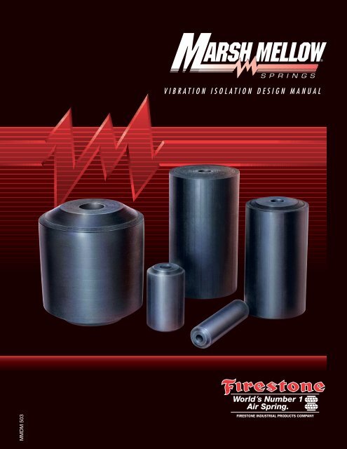
Introduction<br />
<strong>Marsh</strong> <strong>Mellow</strong> ® is the trade name of the fabric and rubber<br />
spring developed by Firestone Industrial Products in the<br />
early 1970's. Rubber springs have long been a subject<br />
of interest in the vehicular suspension and industrial<br />
application fields because of their reliability, corrosion<br />
resistance, low cost, and basic simplicity. The concept<br />
has been tried with varying degrees of success over<br />
the years. The major obstacle to solid rubber springs<br />
has been that to obtain the load requirements for many<br />
applications, solid rubber springs were either physically<br />
too large, or became unstable laterally when they were<br />
made long enough to provide good isolation. The concept<br />
of “stacking” rubber springs answered the latter<br />
problem, but introduced the need for complicated<br />
mechanical guide systems to control the lateral movement.<br />
Individual Data Sheet.....................................................12<br />
Part Number...................................................................12<br />
Table of Dynamic Characteristics .................................12<br />
<strong>Marsh</strong> <strong>Mellow</strong> and Mounting Pin Dimensions .............12<br />
Load/Deflection Curve...................................................13<br />
Selection Procedure (Imperial)......................................14<br />
Vibration Isolation Selection ..........................................14<br />
Vibration Isolation Selection Example ..........................15<br />
Shock Impact Selection.................................................18<br />
Selection Procedure (Metric).........................................19<br />
Vibration Isolation Selection ..........................................19<br />
Vibration Isolation Selection Example ..........................20<br />
Shock Impact Selection.................................................23<br />
Installation........................................................................24<br />
Vibration Isolation New Installation...............................24<br />
Coil Spring Replacement ..............................................25<br />
Miscellaneous Mounting Arrangements .......................26<br />
Applications.....................................................................27<br />
Vibration Isolation...........................................................27<br />
Shock Impact .................................................................27<br />
Tag Line..........................................................................27<br />
Selection Guide (Imperial)..............................................28<br />
Load Requirements .......................................................28<br />
Stroke Requirements.....................................................29<br />
Selection Guide (Metric).................................................30<br />
Load Requirements .......................................................30<br />
Stroke Requirements.....................................................31<br />
Individual Data Pages...............................................32-60<br />
Design Parameter Sheet................................................61<br />
The <strong>Marsh</strong> <strong>Mellow</strong> ® fabric and rubber spring solves this<br />
basic problem and provides a new and unique way to<br />
make use of the many advantages of rubber as an<br />
isolator. The basic construction of the <strong>Marsh</strong> <strong>Mellow</strong> ®<br />
spring includes a solid rubber core with a hollow center,<br />
and fabric reinforced body. The controllable variables of<br />
this construction are the keys to the extreme design<br />
flexibility that the spring offers.<br />
Please Note:<br />
The information contained in this publication is intended to provide<br />
a general guide to the characteristics and applications of these products.<br />
The material, herein, was developed through engineering design<br />
and development, testing and actual applications and is believed to be<br />
reliable and accurate. Firestone, however, makes no warranty,<br />
expressed or implied, of this information. Anyone making use of this<br />
material does so at his own risk and assumes all liability resulting from<br />
such use. It is suggested that competent professional assistance be<br />
employed for specific applications.
Advantages of Firestone<br />
<strong>Marsh</strong> <strong>Mellow</strong> ®<br />
springs<br />
Constant Vibration Isolation<br />
with Changing Loads<br />
The variable spring rate allows for a nearly constant<br />
natural frequency with changing loads. This results in<br />
consistent vibration isolation with variable loading.<br />
High Load Carrying Capacity<br />
Due to the <strong>Marsh</strong> <strong>Mellow</strong> ® spring’s greater deflection<br />
capabilities and load carrying influences of the<br />
fabric reinforcement, it can carry a greater load<br />
when compared to an all rubber part of the same<br />
modulus and dimensions.<br />
Excellent Vibration Isolation<br />
Low natural frequencies provide excellent isolation of<br />
forced frequencies in the range of 800-1200 cycles<br />
per minute (13-20Hz).<br />
Lateral Vibration Isolation<br />
The lateral spring rate of a <strong>Marsh</strong> <strong>Mellow</strong> ® spring<br />
can be less than the vertical spring rate, resulting<br />
in a lower lateral natural frequency. <strong>Marsh</strong> <strong>Mellow</strong><br />
springs provide better vibration isolation in all<br />
degrees of freedom.<br />
Compact Overall Size<br />
The ability to support greater loads and maintain<br />
a cylindrical shape results in a smaller overall size<br />
of the <strong>Marsh</strong> <strong>Mellow</strong> spring compared to an all<br />
rubber spring with identical load capacity. This is<br />
important when considering an application with a<br />
small design envelope.<br />
Corrosion Resistant<br />
for a Durable, Long Life<br />
Due to its rubber and fabric reinforced construction,<br />
the <strong>Marsh</strong> <strong>Mellow</strong> spring has been proven in the<br />
damp and corrosive environments of mines and mills<br />
where a standard coil spring will fail.<br />
Copyright © 1998 Firestone Industrial Products Company<br />
Does Not Bottom-Out<br />
Due to the rubber construction, <strong>Marsh</strong> <strong>Mellow</strong> springs<br />
do not bottom-out like coil springs. Bottoming-out<br />
under overload or surge load sends a large amount of<br />
stress to all of the machine’s components.<br />
Eliminates Downtime and Potential<br />
Damage to Machinery<br />
When a coil spring fails, it will often crack allowing<br />
fragments of the coil to damage equipment. This<br />
problem is eliminated with the rubber construction<br />
of <strong>Marsh</strong> <strong>Mellow</strong> springs. Additionally, <strong>Marsh</strong><br />
<strong>Mellow</strong> springs exhibit exceptionally high overload<br />
characteristics and usually do not fail catastrophically,<br />
offering some support even during failure.<br />
Increased Stability at Higher<br />
Percentages of Compression<br />
Rubber is an incompressible fluid which will flow to<br />
the path of least resistance. In a <strong>Marsh</strong> <strong>Mellow</strong>, as the<br />
height compresses, the fabric reinforced rubber plies<br />
pantograph and the diameter grows. This supports the<br />
rubber core laterally even at 30-40% compression.<br />
Effective Noise Reduction<br />
<strong>Marsh</strong> <strong>Mellow</strong> springs reduce structurally transmitted<br />
noise caused by vibration. <strong>Marsh</strong> <strong>Mellow</strong> springs<br />
are quiet, unlike steel springs which often suffer<br />
coil chatter and readily transmit high frequency<br />
structural noise.<br />
Low Cost<br />
The <strong>Marsh</strong> <strong>Mellow</strong> spring’s high load capability<br />
means fewer springs may be needed in an application,<br />
resulting in less overall cost.<br />
Maintenance Free<br />
<strong>Marsh</strong> <strong>Mellow</strong> springs have no moving parts.<br />
No maintenance or lubrication is required.<br />
3
4<br />
Precautions with <strong>Marsh</strong> <strong>Mellow</strong> ®<br />
springs<br />
Temperature<br />
Our standard industrial <strong>Marsh</strong> <strong>Mellow</strong> springs have<br />
an operating range of -40°F to 135°F (-40°C to 57°C).<br />
The upper limit is defined by the actual rubber<br />
temperature during operation. High frequency inputs<br />
or large deflections will cause the rubber temperature<br />
to increase.<br />
Design Envelope<br />
Adequate clearance should be provided around the<br />
<strong>Marsh</strong> <strong>Mellow</strong> spring to prevent rubbing of the outer<br />
cover. The outside diameter of the spring at various<br />
heights is listed in the table of dynamic characteristics<br />
on each individual data page.<br />
Contaminates<br />
Shielding should be used to protect the rubber from<br />
exposure to hot metal, petroleum base fluids, acids,<br />
etc. Please consult Firestone if you wish to know<br />
how the spring will withstand a specific contaminate.<br />
(For liquids such as acids, it is important to know both<br />
concentration and temperature.)<br />
Storage<br />
The best storage environment is a dark, dry area at<br />
normal room temperature.<br />
Percent Compression<br />
The general compression range of a <strong>Marsh</strong> <strong>Mellow</strong><br />
spring is 15% to 27%, however this value may vary<br />
somewhat among springs and applications. Always<br />
follow the load ranges and their corresponding compression<br />
percentages as shown in the selection guide.<br />
Allowable Stroke<br />
When applying a <strong>Marsh</strong> <strong>Mellow</strong> spring, the stroke<br />
throughout the range of motion of the machine being<br />
isolated must be considered. Delta strain, defined as<br />
the ratio of the stroke to the free length, is restricted<br />
to less than 7.5%.<br />
Note that a given stroke is typical of vibrating screen<br />
types of applications, where the stroke is designed into<br />
the system. In other isolation applications, this stroke<br />
may not be known. The stroke is typically not excessive<br />
in standard isolation applications, but should be<br />
considered. Consult Firestone for assistance.<br />
Disturbing Frequency Range<br />
<strong>Marsh</strong> <strong>Mellow</strong>s are suitable for disturbing frequencies in<br />
the 800-1200 CPM (13-20Hz) range for medium stroke<br />
applications. High frequency, high stroke applications<br />
may lead to overheating the <strong>Marsh</strong> <strong>Mellow</strong> spring. Low<br />
stroke applications, however, are capable of handling<br />
higher disturbing frequencies. Please consult Firestone<br />
Industrial Products with specific applications.<br />
Lateral Stability<br />
The lateral spring rate to load ratio for a <strong>Marsh</strong><br />
<strong>Mellow</strong> spring decreases as deflection increases.<br />
This is one reason it is important not to exceed the<br />
given load capabilities.
Precautions with <strong>Marsh</strong> <strong>Mellow</strong> ®<br />
springs<br />
Center of Gravity<br />
A <strong>Marsh</strong> <strong>Mellow</strong> spring isolation system is inherently soft<br />
(easily deflected); therefore, precautions must be taken<br />
to insure that the system is stable. First consider the<br />
location of the center of gravity (CG). Ideally, <strong>Marsh</strong><br />
<strong>Mellow</strong> springs should be located on the same plane<br />
(parallel to the ground) as the center of gravity. Where<br />
this is not possible, follow this guideline: The distance<br />
between the narrowest mounting points should be at<br />
least twice the height of the center of gravity.<br />
Height 48"<br />
Width 46"<br />
Length 50"<br />
In the above example, the most narrow distance<br />
between two <strong>Marsh</strong> <strong>Mellow</strong> springs is 46 inches<br />
(117 cm). The height to the CG is 48 inches (122 cm);<br />
therefore, this system does not meet our guideline.<br />
Two possible solutions would be:<br />
1. Increase the base dimensions to meet our guideline<br />
by increasing both the width and length to at<br />
least 48 x 2 or 96 inches (122 x 2 or 244 cm).<br />
2. Locate the <strong>Marsh</strong> <strong>Mellow</strong> spring at the CG<br />
as shown below.<br />
Startup and Shutdown / Resonance<br />
and Amplification<br />
Resonance is the condition where the forced<br />
frequency of the vibrating system is equal to the<br />
natural frequency of the suspension. When this<br />
happens, amplification of movement occurs. If the<br />
normal stroke of a vibrating screen, for example, is<br />
5/16 of an inch (8 mm), during startup and shutdown<br />
(as the machine goes through resonance), the<br />
amplitude of movement will be multiplied. So while<br />
the machine is accelerating to normal operating speed<br />
and decelerating during shutdown, the stroke may be<br />
amplified in the range of 1 ⁄2 (12 mm) to<br />
1 1 ⁄2 (38 mm) inches. The longer the machine<br />
takes to go through resonance (to speed up to,<br />
or slow down from full operating speed), the larger<br />
the amplitude of movement. Note that in some<br />
applications, the addition of viscous or friction<br />
dampers may be required to reduce the amplitude of<br />
motion during startup and shutdown.<br />
Isolating an Unbalanced Mass<br />
The primary concern in this case is the amplitude of<br />
movement. It is dependent on:<br />
1. The ratio of the unbalanced moving mass to the<br />
total suspended mass, and<br />
2. The ratio of the speed of the unbalanced moving<br />
mass (forced frequency) to the natural frequency<br />
of the <strong>Marsh</strong> <strong>Mellow</strong> spring and supported<br />
mass system.<br />
The addition of damping to the isolation system<br />
(“shock absorbers”) will reduce the large amplitude<br />
of movement experienced during resonance.<br />
If the amplitude of movement is too great, one<br />
possible solution would be to add a static inertia base<br />
in order to increase the ratio of the total suspended<br />
mass to the moving unbalanced mass. A good “rule of<br />
thumb” is 10:1, respectively.<br />
See page 10 for additional information.<br />
5
6<br />
<strong>Marsh</strong> <strong>Mellow</strong> ®<br />
spring Construction<br />
Solid Rubber Core<br />
Unique construction elements are the key to the<br />
<strong>Marsh</strong> <strong>Mellow</strong> ® spring’s design flexibility. The basic<br />
construction of the <strong>Marsh</strong> <strong>Mellow</strong> spring includes a<br />
solid rubber core with a hollow center, and several<br />
plies of fabric reinforced rubber as an outer cover.<br />
These elements may be modified to meet specific<br />
load and performance requirements.<br />
Solid Rubber Core Material<br />
The rubber material of the <strong>Marsh</strong> <strong>Mellow</strong> spring<br />
has a large effect on the performance of the spring<br />
as well as to what application it is suited. The rubber<br />
material used in vibration isolation applications is<br />
efficient and provides little damping. Higher damping<br />
compounds are available but better suit shock<br />
absorbing applications. The correct rubber core<br />
material is application dependent.<br />
Hollow Center<br />
The diameter of the hollow center is another variable<br />
in the load capacity of the <strong>Marsh</strong> <strong>Mellow</strong> spring.<br />
The hollow center directly affects the contact area<br />
over which force is applied. As expected, a smaller<br />
diameter center will support a greater load compared<br />
to an otherwise identical <strong>Marsh</strong> <strong>Mellow</strong> spring.<br />
The hollow center also permits mounting the <strong>Marsh</strong><br />
<strong>Mellow</strong> spring in a variety of applications. These<br />
mounting arrangements are discussed in greater<br />
detail within the “Installation and Mounting<br />
Arrangements” section of the <strong>Marsh</strong> <strong>Mellow</strong><br />
Spring Design Manual.<br />
Hollow Center<br />
Fabric<br />
Reinforcement<br />
Cover Stock<br />
Fabric Reinforcement<br />
The fabric reinforced rubber has a large effect on<br />
the performance of the <strong>Marsh</strong> <strong>Mellow</strong> springs. In<br />
appearance, <strong>Marsh</strong> <strong>Mellow</strong> springs are cylindrical in<br />
shape with a hollow center the entire length of the<br />
part. What separates the <strong>Marsh</strong> <strong>Mellow</strong> spring from<br />
an all rubber part of the same dimensions is its<br />
bias plies of fabric reinforced rubber. The plies, which<br />
surround the rubber core material, provide stability and<br />
a consistent cylindrical shape. The angle which the<br />
plies are laid upon each other may be manipulated to<br />
meet application specific requirements.<br />
The performance of the <strong>Marsh</strong> <strong>Mellow</strong> spring is<br />
influenced by several variables. If the models<br />
provided within this catalog do not meet your<br />
engineering requirements, please contact Firestone<br />
Industrial Products. By modifying the construction<br />
details, we may be able to meet your needs.<br />
Cover Stock<br />
The cover rubber aids in abrasion resistance and<br />
protects the inner layers of fabric reinforcement.<br />
This is not intended to take the place of an adequate<br />
design envelope. Please consult data pages for<br />
outside diameter dimensions, and allow for adequate<br />
space to avoid abrasion.
<strong>Marsh</strong> <strong>Mellow</strong> ®<br />
spring Dynamic Characteristics<br />
This section includes terminology associated with the<br />
dynamic characteristics of the <strong>Marsh</strong> <strong>Mellow</strong> ® spring.<br />
The terminology is defined both quantitatively and<br />
qualitatively. This information will help in determining<br />
which spring best suits an application, whether it is<br />
vibration isolation, isolating an unbalanced mass, or<br />
shock absorption.<br />
Vibration Isolation<br />
Vibration (disturbing frequency)<br />
The periodic motion of a body, measured in cycles<br />
per minute.<br />
Isolator<br />
An isolator is a device which allows two objects<br />
to exist without influencing each other. For example,<br />
a <strong>Marsh</strong> <strong>Mellow</strong> spring prevents a vibrating object<br />
from affecting the surrounding environment while still<br />
allowing the object to vibrate.<br />
Spring Rate<br />
Spring rate is defined as the amount of force required<br />
to deflect a spring 1 inch. Graphically, spring rate is<br />
equal to the slope of the load/deflection curve at the<br />
corresponding load. A steel coil spring has a constant<br />
spring rate as shown by the straight line on the<br />
load/deflection chart below. The slope of a <strong>Marsh</strong><br />
<strong>Mellow</strong> spring curve changes with height. This results<br />
in a changing spring rate. These characteristics are<br />
illustrated below:<br />
Spring Rate = Force = Slope of the Load/Deflection Curve<br />
Deflection<br />
Load/Deflection Curves<br />
3000<br />
LOAD<br />
L<br />
1.0" 2.0" 3.0" 4.0" 5.0" 6.0"<br />
STEEL<br />
LOAD/DEFLECTION CURVES<br />
MARSH MELLOW<br />
da<br />
de<br />
C<br />
DEFLECTION<br />
Effective Deflection<br />
Because the slope of the <strong>Marsh</strong> <strong>Mellow</strong> spring<br />
load/deflection curve changes, the spring rate must<br />
be expressed in terms of effective deflection and load.<br />
Effective deflection is the difference between actual<br />
deflection and the x intercept of the tangent line to the<br />
load curve at the design load. Effective deflection is also<br />
equal to the given load divided by the slope of the load<br />
curve at that point.<br />
Effective Deflection (in) = Load (lbs)<br />
Spring Rate (lbs / in)<br />
Effective Deflection (m) = Load (kN)<br />
Spring Rate (kN / m)<br />
Since the spring rate of a coil spring is constant,<br />
the effective deflection is equivalent to the actual<br />
deflection. A <strong>Marsh</strong> <strong>Mellow</strong> spring’s spring rate<br />
increases as the load increases, therefore the<br />
effective deflection is almost constant. This results<br />
in a consistent isolator with changing loads.<br />
LOAD LBS. X 1000<br />
15<br />
10<br />
5<br />
LOAD<br />
LB.<br />
5000<br />
2000<br />
EFFECTIVE<br />
DEFLECTION<br />
1.6"<br />
LOAD DEFLECTION CURVE<br />
RATE<br />
LB./IN.<br />
3125<br />
1250<br />
EFFECTIVE<br />
DEFLECTION<br />
1.6"<br />
1.6"<br />
TANGENT TO CURVE<br />
EFFECTIVE<br />
DEFLECTION<br />
1.6"<br />
10 9 8 7 6 5<br />
HEIGHT IN.<br />
NATURAL<br />
FREQ. CPM<br />
149<br />
149<br />
Spring Height Load Actual Effective Spring<br />
Type Deflection Deflection Rate<br />
Coil Spring 7.3 in 1500lbs 1.2 in 1.2 in 1200 lb/in<br />
Coil Spring 6.0 in 3000lbs 2.5 in 2.5 in 1200 lb/in<br />
<strong>Marsh</strong> <strong>Mellow</strong> 6.0 in 1500lbs 2.5 in 1.8 in 810 lb/in<br />
<strong>Marsh</strong> <strong>Mellow</strong> 4.8 in 3000lbs 3.7 in 1.8 in 1620 lb/in<br />
7
8<br />
<strong>Marsh</strong> <strong>Mellow</strong> ®<br />
spring<br />
Dynamic Characteristics<br />
Natural Frequency<br />
A spring system’s natural frequency determines the<br />
efficiency of an isolator. Effective isolators have a low<br />
natural frequency.<br />
Natural Frequency (CPM) = 188 x Spring Rate (lbs / in)<br />
Load (lbs)<br />
= 188<br />
Effective Deflection (in)<br />
Natural Frequency (Hz) = 0.50 x Spring Rate (kN / m)<br />
Load (kN)<br />
= 0.50<br />
Effective Deflection (m)<br />
FORCED FREQUENCY (ff)<br />
HERTZ<br />
50<br />
41.7<br />
33.2<br />
3000<br />
2500<br />
2000<br />
25 1500<br />
16.7<br />
15<br />
13.3<br />
11.7<br />
10<br />
8.3<br />
6.7<br />
5.0<br />
4.2<br />
3.3<br />
2.5<br />
1.7<br />
CPM<br />
1000<br />
900<br />
800<br />
700<br />
600<br />
500<br />
400<br />
300<br />
250<br />
200<br />
150<br />
Percent<br />
Isolation<br />
99.9<br />
30<br />
0.50 40<br />
0.67 50<br />
0.83 60<br />
1.0 80<br />
1.33 100<br />
100<br />
1.67<br />
Disturbing Frequency<br />
Disturbing frequency is the frequency of the motion<br />
which needs to be isolated. This is usually expressed<br />
in cycles per minute (CPM) or cycles per second (Hz).<br />
As an example, the disturbing frequency of a motor is<br />
the number of revolutions per minute. The lower the<br />
disturbing frequency is, the more difficult it is to isolate.<br />
Transmissibility<br />
Transmissibility is the amount of vibration energy<br />
which is transmitted from the vibrating source to the<br />
surrounding environment.<br />
% Transmission =<br />
100<br />
2<br />
Disturbing Freq (CPM) [ Natural Freq (CPM) ] -1<br />
Isolation<br />
Isolation is the amount of vibration energy prevented<br />
from being transmitted through the isolator.<br />
% Isolation = 100% - Transmissibility<br />
This equation is illustrated in the chart below.<br />
ISOLATION CHART<br />
99.5 99 98 97 9695 90 80 70 60<br />
150<br />
2.50 200<br />
3.33<br />
Resonance<br />
NATURAL FREQUENCY (fn)<br />
Amplification<br />
300<br />
5.00 400<br />
6.67 500<br />
8.33 600<br />
10.0 800<br />
13.3 1000<br />
16.7 CPM<br />
HERTZ
<strong>Marsh</strong> <strong>Mellow</strong> ®<br />
spring<br />
Dynamic Characteristics<br />
Resonance<br />
Resonance occurs when the disturbing frequency<br />
equals the natural frequency of the <strong>Marsh</strong> <strong>Mellow</strong><br />
spring system. When this occurs the amplitude of<br />
vibration will increase without bound. The system is<br />
unstable at resonance.<br />
Amplification<br />
Amplification occurs when the disturbing frequency is<br />
less than 1.4 times the natural frequency. The vibrating<br />
motion is amplified in this range.<br />
Amplitude<br />
Amplitude is the amount of motion associated with the<br />
vibration. Quantitatively, the amplitude is half of the<br />
total peak to peak distance. On the figure below it is<br />
defined as X 1 and X 2.<br />
x<br />
x1 x2 r<br />
STROKE<br />
(MM)<br />
(IN)<br />
40<br />
35<br />
30<br />
25<br />
20<br />
15<br />
10<br />
5<br />
0<br />
1.6<br />
1.4<br />
1.2<br />
1.0<br />
0.8<br />
0.6<br />
0.4<br />
0.2<br />
t<br />
Stroke<br />
The stroke is the total peak to peak distance the<br />
machine moves during operation. It is equal to twice<br />
the amplitude.<br />
Strain<br />
<strong>Marsh</strong> <strong>Mellow</strong> springs will survive a defined amount of<br />
movement from vibrating equipment. The amount of<br />
movement, or stroke, allowed is measured in delta<br />
strain. Delta strain is dependent upon stroke and the<br />
free height of the <strong>Marsh</strong> <strong>Mellow</strong> spring.<br />
∆Strain = Stroke (in or mm) x 100%<br />
Free Height (in or mm)<br />
The maximum delta strain allowed for the <strong>Marsh</strong><br />
<strong>Mellow</strong> spring is 7.5%. The following delta chart<br />
shows the relationship of free height, stroke, and<br />
delta strain.<br />
MARSH MELLOW SPRING STRAIN CHART<br />
0<br />
0 2 4 6 8 10 12 14 16 18 20 (IN)<br />
0 51 102 153 203 254 305 356 406 458 508 (MM)<br />
FREE HEIGHT<br />
7.5%<br />
6.5%<br />
5.5%<br />
4.5%<br />
3.5%<br />
2.5%<br />
1.5%<br />
9
10<br />
<strong>Marsh</strong> <strong>Mellow</strong> ®<br />
spring<br />
Dynamic Characteristics<br />
Isolating an Unbalanced Mass<br />
Excursion<br />
Excursion is the amount of movement caused by a<br />
moving mass. An isolator will not decrease this movement.<br />
Excursion, however, can be controlled through<br />
dampers or by increasing the static mass. Excursion<br />
is directly proportional to the ratio of moving mass to<br />
static mass. The smaller the ratio is, the smaller the<br />
amount of excursion. A good “rule of thumb” is a static<br />
mass no smaller than 10 times the moving mass.<br />
Excursion(in or mm) ~ MovingMass(lbs or kN)<br />
StaticMass(lbs or kN)<br />
Static, or Inertia, Mass<br />
Static, or inertia, mass is a heavy base used to<br />
decrease the amount of movement caused by a<br />
smaller moving mass.<br />
Eccentricity<br />
Eccentricity is the radius a moving mass rotates,<br />
thereby causing excursion. The larger the eccentricity,<br />
the greater the amount of excursion.<br />
Total<br />
mass<br />
M<br />
k<br />
r<br />
ω<br />
Static Mass<br />
b=Damper<br />
k=Isolator<br />
m=Moving Mass<br />
r=Eccentricity<br />
x=Excursion<br />
ω=Rotational Velocity,<br />
Disturbing Frequency<br />
m<br />
b<br />
x
FORCE POUNDS X 10'<br />
FORCE POUNDS X 10'<br />
14.0<br />
12.0<br />
10.0<br />
8.0<br />
6.0<br />
4.0<br />
2.0<br />
HIGH DAMPING CURVE<br />
HIGH DAMPING<br />
4 1 /8 X 1 X 10<br />
<strong>Marsh</strong>mellow Dimensions<br />
0<br />
10.0 9.0 8.0 7.0 6.0 5.0<br />
7.0<br />
6.0<br />
5.0<br />
4.0<br />
3.0<br />
2.0<br />
1.0<br />
HEIGHT IN INCHES<br />
LOW DAMPING CURVE<br />
LOW DAMPING<br />
4 1 /8 X 1 X 10<br />
<strong>Marsh</strong>mellow Dimensions<br />
0<br />
10.0 9.0 8.0 7.0 6.0 5.0<br />
HEIGHT IN INCHES
12<br />
Individual Data Sheet<br />
On each individual data sheet detailed information<br />
is provided on a specific <strong>Marsh</strong> <strong>Mellow</strong> spring.<br />
Each sheet contains four main components.<br />
• Part Number<br />
• Table of Dynamic Characteristics<br />
• Drawing showing <strong>Marsh</strong> <strong>Mellow</strong> spring<br />
Dimensions and Mounting Pin Dimensions<br />
• Load/Deflection Curve<br />
Part Number<br />
The part number of the <strong>Marsh</strong> <strong>Mellow</strong> spring is shown<br />
at the top of the data sheet. The part number will start<br />
with W22-358- – – – – . The last four digits are specific<br />
for each <strong>Marsh</strong> <strong>Mellow</strong> spring.<br />
Table of Dynamic Characteristics<br />
The Table of Dynamic Characteristics contains critical<br />
information needed to select the correct <strong>Marsh</strong> <strong>Mellow</strong><br />
spring. The range of allowable percentages of<br />
compression are given at the top of the table. The<br />
corresponding heights and loads, as well as the<br />
spring rate and effective deflection, are listed below<br />
the percentages of compression. It is necessary to<br />
know the natural frequency of the <strong>Marsh</strong> <strong>Mellow</strong><br />
spring to determine the percentage of isolation.<br />
The outside diameter of the <strong>Marsh</strong> <strong>Mellow</strong> spring<br />
throughout the allowable compression is listed in<br />
order to check the design envelope.<br />
(W22-358-0176)<br />
IMPERIAL<br />
Compression (%) 15.0 20.0 22.5 25.0 27.5<br />
Load (lbs.) 2300 3350 4000 4600 5300<br />
Height (in.) 8.5 8.0 7.8 7.5 7.3<br />
Rate (lbs./in.) 2000 2400 2500 2600 3100<br />
Effective Deflection (in.) 1.15 1.40 1.60 1.77 1.71<br />
Natural Freq. (CPM) 175 159 149 141 144<br />
Maximum OD (in.) 7.9 8.1 8.3 8.4 8.6<br />
<strong>Marsh</strong> <strong>Mellow</strong> spring and Mounting<br />
Pin Dimensions<br />
A <strong>Marsh</strong> <strong>Mellow</strong> spring has three important<br />
dimensions: outside diameter, inside diameter,<br />
and free height. The three dimensions illustrated on<br />
the data sheet are at an unloaded state. The heights<br />
and outside diameters of the <strong>Marsh</strong> <strong>Mellow</strong> spring<br />
under loaded conditions are listed in the table of<br />
dynamic characteristics.<br />
10"<br />
7.5"<br />
3.5"<br />
9.25"<br />
(Min. Dia.)<br />
@ Maximum Load<br />
The mounting pin dimensions for the specific spring<br />
are needed for installation. These given dimensions<br />
are for typically mounting the <strong>Marsh</strong> <strong>Mellow</strong> spring in<br />
vibration isolation applications. The height of the<br />
mounting pin, and mounting plate diameter, are the<br />
minimum values allowed at maximum loading. The<br />
pin diameter should be equal to the inside diameter<br />
of the spring.<br />
1.5"<br />
3.5"
Individual Data Sheet<br />
Load/Deflection Curve<br />
The load/deflection curve shows the load vs. height<br />
of the <strong>Marsh</strong> <strong>Mellow</strong> spring.<br />
In order to determine the height of the <strong>Marsh</strong> <strong>Mellow</strong><br />
spring at a given load, use the load/deflection curve.<br />
Move horizontally on the chart from the given load on<br />
the vertical axis. Stop and make a fixed point at the<br />
compression curve. The height directly below this<br />
point on the x axis is the height of the <strong>Marsh</strong> <strong>Mellow</strong><br />
spring at the given load. This procedure is shown on<br />
the chart below with a given load of 4000 lbs.<br />
12000<br />
8000<br />
6000<br />
Load (lbs.) 10000<br />
4000<br />
2000<br />
0<br />
10.0 9.5 9.0 8.5 8.0 7.5 7.0 6.5 6.0<br />
Minimum<br />
Maximum<br />
Compression<br />
Compression<br />
(8.5)<br />
(7.25)<br />
Height (in.)<br />
1. Proceed right horizontally from a load of 4000 lbs.<br />
2. Stop and make a fixed point directly on the<br />
compression curve.<br />
3. Proceed straight down to the horizontal axis.<br />
4. The intersection at the horizontal axis is the height<br />
at the given load, 7.8 inches.<br />
LOAD/DEFLECTION CURVE<br />
13
14<br />
Selection Procedure (Imperial)<br />
Vibration Isolation Selection<br />
1. For specific design parameters needed to determine<br />
the correct <strong>Marsh</strong> <strong>Mellow</strong> spring for an application,<br />
consult the “Design Parameter Sheet” on page 61.<br />
2. If possible, determine the load at each mounting<br />
point. If this is not possible, estimate the load on<br />
the <strong>Marsh</strong> <strong>Mellow</strong> spring by adding the weight of<br />
the machine plus the weight of the materials on<br />
the machine while operating, then divide the total<br />
weight by the number of <strong>Marsh</strong> <strong>Mellow</strong> springs to<br />
be used. This estimate will only be accurate if the<br />
load’s center of gravity is equidistant from each<br />
mounting point. If the weight of the machine is<br />
unknown, contact the equipment manufacturer,<br />
your distributor or Firestone for assistance.<br />
Firestone’s or your distributor’s machine weight<br />
estimates are based on the manufacturer’s published<br />
weights of current models of the same size<br />
and type. Weight consideration must be given to a<br />
special machine, modified machines, or older<br />
machines that will add weight to the unit.<br />
3. Select a spring that falls in the mid-range of the<br />
minimum and maximum load capacities shown<br />
in the “Selection Guide”. For maximum life and<br />
stability, it is suggested that <strong>Marsh</strong> <strong>Mellow</strong> springs<br />
be used at or less than 25% (of free height) actual<br />
static deflection. Although the maximum loading<br />
figures in the above selection guide are given at<br />
27.5% deflection (and these <strong>Marsh</strong> <strong>Mellow</strong> ® springs<br />
all pass our lateral stability test at up to 30%<br />
deflection), the lateral rate to load ratio decreases<br />
as deflection increases. The extra 2.5% deflection,<br />
then, is a safety factor for possible weight miscalculations.<br />
Additionally, the delta strain (Stroke/Free<br />
Length x 100) should not exceed 7.5%.<br />
4. If more than one spring meets the load criteria<br />
in number 2, then select the spring with the<br />
lowest natural frequency (isolation percentage<br />
will be increased).<br />
5. Determine the stroke required.<br />
6. Refer to the second selection guide table.<br />
Check to make sure that for a given stroke<br />
and part, the height and load are within<br />
the allowable limits given.<br />
7. If it does not fall within the proper range, then<br />
select a different spring or go to more than one<br />
<strong>Marsh</strong> <strong>Mellow</strong> ® spring per corner.<br />
8. Consult the individual data page for the specific<br />
load and vibration capabilities, as well as<br />
mounting and <strong>Marsh</strong> <strong>Mellow</strong> spring dimensions.<br />
9. Determine if the natural frequency of the<br />
<strong>Marsh</strong> <strong>Mellow</strong> spring will sufficiently isolate<br />
the disturbing vibration.<br />
10. Tag lines are usually required for inclined screens<br />
or screens with off-mounted pivoted motors.<br />
(Consider using our tension band W22-358-0215<br />
or W22-358-0275).<br />
11. Please review the “Installation” section of<br />
the <strong>Marsh</strong> <strong>Mellow</strong> Spring Design Manual for<br />
additional information.
Selection Procedure (Imperial)<br />
Vibration Isolation Selection Example<br />
The following example follows the correct procedure<br />
in determining which <strong>Marsh</strong> <strong>Mellow</strong> spring best suits<br />
a given set of requirements.<br />
The vibrating screen illustrated to the right has the<br />
following description and design requirements:<br />
Description of Equipment = Vibrating screen<br />
Total Weight of Machine = 12000 lbs.<br />
Total Material Load = 4000 lbs.<br />
Number of Mounting Points = 4<br />
Space Available =10 inch diameter<br />
footprint<br />
Stroke = 1/2 inch<br />
Disturbing Frequency = 1000CPM<br />
Percent Isolation Desired = 90%<br />
1. Determine Individual Spring Load<br />
The exact load at each mounting point is not<br />
available, so the individual loads must be estimated.<br />
The minimum load each spring will support is<br />
assumed to be equal to the machine weight divided<br />
by the number of mounting points.<br />
Machine Load(lbs) 12000lbs = 3000lbs per spring<br />
Minimum Load = # of Mounting Points =<br />
4<br />
The maximum load is equal to the machine load plus the weight of the material.<br />
Maximum Load = (Machine + Material Load)lbs = (12000 + 4000)lbs = 4000lbs per spring<br />
# of Mounting Points 4<br />
2. Examine <strong>Marsh</strong> <strong>Mellow</strong> Spring<br />
Load Capabilities<br />
From the “Selection Guide - Load Capabilities”, seven<br />
different <strong>Marsh</strong> <strong>Mellow</strong> springs will support load range<br />
from 3000lbs. to 4000lbs. The W22-358-0200, 0176,<br />
0042, 0190, 0179, 0122, and 0228. As discussed in<br />
the “Dynamic Characteristics” section, a lower natural<br />
frequency <strong>Marsh</strong> <strong>Mellow</strong> spring will provide better<br />
isolation. Since the W22-358-0176 has a low natural<br />
frequency at both minimum and maximum loading,<br />
we will select this part for the example.<br />
3'<br />
16'<br />
3. Determine Stroke Requirement<br />
The required stroke for this screen is 0.5 inches with<br />
a maximum load of 4000lbs. On the “Selection Table -<br />
Stroke Requirements”, the 0176 has a maximum<br />
stroke capability of 0.5 inches with a load range of<br />
1940 to 4540lbs. The 0176 meets this requirement.<br />
6'<br />
15
16<br />
Selection Procedure (Imperial)<br />
4. Determine Exact % Isolation<br />
The percentage of isolation can either be calculated<br />
or the % Isolation chart may be used. The first step<br />
is to refer to the individual data page for necessary<br />
information. The Dynamic Characteristics table will<br />
provide this data.<br />
IMPERIAL<br />
Compression (%) 15.0 20.0 22.5 25.0 27.5<br />
Load (lbs.) 2300 3350 4000 4600 5300<br />
Height (in.) 8.5 8.0 7.8 7.5 7.3<br />
Rate (lbs./in.) 2000 2400 2500 2600 3100<br />
Effective Deflection (in.) 1.15 1.40 1.60 1.77 1.71<br />
Natural Freq. (CPM) 175 159 149 141 144<br />
Maximum OD (in.) 7.9 8.1 8.3 8.4 8.6<br />
At the minimum load of 3000lbs, the 0176 is between 15% and 20% compression.<br />
We can interpolate this data and estimate the natural frequency at minimum load.<br />
MinimumLoad - Load@15%<br />
=<br />
NaturalFreq - NaturaIFreq@15%<br />
Load@20% - Load@15% NaturaIFreq@20% - NaturaIFreq@15%<br />
[(MinimumLoad - Load@15%) x (NatFreq@20% - NatFreq@15%)]<br />
NaturalFreq = NatFreq@15% +<br />
Load@20% - Load@15%<br />
[(3000 - 2300)lbs x (159 - 175)CPM)]<br />
NaturalFreq = 175CPM +<br />
(3350 - 2300)lbs<br />
NaturalFreq@3000lbs = 164CPM<br />
We can interpolate the natural frequency at the maximum load of 4000lbs in a similar way.<br />
However, in this case we know the natural frequency at 4000lbs directly from the data table.<br />
NaturalFreq@4000lbs = 149CPM<br />
Knowing these natural frequencies, as well as the disturbing frequency, allows us to determine<br />
the exact % isolation with the following equations:<br />
100<br />
%Isolation = 100 -<br />
DisturbingFreq2 NaturalFreq<br />
-1<br />
%Isolation@3000lbs = 100 - 100<br />
1000CPM 2<br />
[ ]<br />
( )<br />
[ ] ( -1<br />
164CPM )<br />
%Isolation@3000lbs. = 97.2%<br />
%Isolation@4000lbs = 100 - 100<br />
%Isolation@4000/lbs = 97.7%<br />
1000CPM 2 [ ]<br />
( -1<br />
149CPM )<br />
(Note: The percentage of isolation is relatively constant with changing loads.)
Selection Procedure (Imperial)<br />
FORCED FREQUENCY (ff)<br />
HERTZ CPM<br />
50 3000<br />
41.7 2500<br />
33.2 2000<br />
25 1500<br />
16.7<br />
15<br />
13.3<br />
11.7<br />
10<br />
8.3<br />
6.7<br />
5.0<br />
4.2<br />
3.3<br />
2.5<br />
1.7<br />
1000<br />
900<br />
800<br />
700<br />
600<br />
500<br />
400<br />
300<br />
250<br />
200<br />
150<br />
The percentage of isolation can also be determined<br />
using the % isolation chart shown above.<br />
The diagonal lines across the chart represent specific<br />
isolation percentages. The intersection point, where<br />
the forced frequency and natural frequency meet,<br />
will lie on or between these diagonal lines. As shown<br />
above, the forced frequency of 1000 CPM and the<br />
natural frequencies of 149 and 164 CPM result in<br />
97-98% isolation.<br />
The percent isolation of 97% exceeds the required<br />
isolation of 90%.<br />
5. Determine Exact Strain<br />
The maximum allowable delta strain a <strong>Marsh</strong><br />
<strong>Mellow</strong> spring can withstand is 7.5%. In order to<br />
calculate this we need to know the free height of<br />
the <strong>Marsh</strong> <strong>Mellow</strong> spring. Strain is equal to the<br />
stroke, 0.5 inches, divided by the free height.<br />
∆Strain = Stoke (in) x 100%<br />
FreeHeight (in)<br />
Percent<br />
Isolation<br />
∆Strain = 0.5 inches x l00% = 5%<br />
10 inches<br />
100<br />
30 40 50 60 80 100<br />
0.50 0.67 0.83 1.0 1.33 1.67<br />
The required stroke is within the 0176’s limitations.<br />
PERCENT ISOLATION CHART<br />
99.9<br />
99.5 99 98 97 9695 90 80 70 60<br />
150<br />
2.50<br />
200<br />
3.33<br />
Resonance<br />
NATURAL FREQUENCY (fn)<br />
Amplification<br />
300 400 500 600 800 1000 CPM<br />
5.00 6.67 8.33 10.0 13.3 16.7 HERTZ<br />
6. Design Envelope Requirements<br />
The Dynamic Characteristics Table shows that the<br />
outside diameter meets the space requirements<br />
of a minimum 10 inch diameter footprint. The OD is<br />
given at various heights between 15% and 27.5%<br />
compression. The OD of the <strong>Marsh</strong> <strong>Mellow</strong> spring at<br />
26% compression is approximately 8.5 inches. The<br />
height of the <strong>Marsh</strong> <strong>Mellow</strong> spring can easily be read<br />
from the load deflection curve. From the previous<br />
section “Individual Data Sheet, Load Deflection<br />
Curve” we determined the height of the 0176 with<br />
a load of 4000 lbs is 7.8 inches.<br />
7. Lateral Stability<br />
As shown on the sketch of the equipment, the <strong>Marsh</strong><br />
<strong>Mellow</strong> springs are mounted within the recommended<br />
distance of the center of gravity. The 0176 is also<br />
being used between 15% and 27.5% compression for<br />
maximum lateral stability. For additional stability with<br />
inclined screens or screen with off-mounted pivot<br />
motors, Firestone tension bands are often used as tag<br />
lines. The W22-358-0215 and 0275 tension bands are<br />
widely used in this application.<br />
17
18<br />
Selection Procedure (Imperial)<br />
Shock Impact Selection<br />
<strong>Marsh</strong> <strong>Mellow</strong> springs are commonly found on<br />
overhead cranes and other bumper applications.<br />
The following are the basic guidelines in determining<br />
the correct <strong>Marsh</strong> <strong>Mellow</strong> spring under shock<br />
impact conditions.<br />
Calculating the Required<br />
Energy Dissipation<br />
To size the proper <strong>Marsh</strong> <strong>Mellow</strong> spring, the amount of<br />
energy generated by the moving object must be known.<br />
There are several ways to calculate this.<br />
For a free falling mass without an initial velocity:<br />
The following will calculate the amount of energy that<br />
needs to be absorbed for a free falling mass which<br />
starts at rest.<br />
Potential Energy = mass x gravity/height (lb force•inches)<br />
mass x gravity = the weight of the object (lb force)<br />
height = the height the object begins its<br />
descent (inches)<br />
For a free falling mass with an initial velocity:<br />
This calculation models a falling mass which has an<br />
initial velocity. The energy generated during free fall<br />
must be added to the kinetic energy associated with<br />
its initial velocity.<br />
Kinetic Energy = 1/2 x mass x velocity2 (lb force•inches)<br />
Potential Energy = see calculation for free falling<br />
mass without initial velocity<br />
mass = weight (lb force)<br />
386<br />
velocity = initial velocity before free fall<br />
inches<br />
( seconds)<br />
For a horizontal impact or if the velocity immediately<br />
before impact is known:<br />
Under these conditions the kinetic energy generated<br />
by velocity must be calculated.<br />
Kinetic Energy = 1/2 x mass x velocity2 (lb force•inches)<br />
mass = weight (lb force)<br />
386<br />
velocity = velocity object inches<br />
(<br />
second )<br />
<strong>Marsh</strong> <strong>Mellow</strong> Spring Selection<br />
After the amount of energy needed to be absorbed<br />
is calculated, the proper <strong>Marsh</strong> <strong>Mellow</strong> spring for<br />
the application may be determined. Please contact<br />
Firestone Industrial Products to select the correct<br />
<strong>Marsh</strong> <strong>Mellow</strong> spring which has at least the same<br />
amount of absorbed energy capability as required<br />
for the application.<br />
Note: While the marshmellow will absorb the impact<br />
energy on the compression stroke and dissipate<br />
some amount of this energy, it will still return<br />
some of the energy in the form of a rebound<br />
stroke. In some applications, viscous or friction<br />
dampers may be required to control the speed<br />
of the rebound stroke.
Selection Procedure (Metric)<br />
Vibration Isolation Selection<br />
1. For specific design parameters needed to determine<br />
the correct <strong>Marsh</strong> <strong>Mellow</strong> spring for an application,<br />
consult the “Design Parameter Sheet” on page 61.<br />
2. If possible, determine the load at each mounting<br />
point. If this is not possible, estimate the load on<br />
the <strong>Marsh</strong> <strong>Mellow</strong> spring by adding the weight of<br />
the machine plus the weight of the materials on<br />
the machine while operating, then divide the total<br />
weight by the number of <strong>Marsh</strong> <strong>Mellow</strong> springs to<br />
be used. This estimate will only be accurate if the<br />
load’s center of gravity is equidistant from each<br />
mounting point. If the weight of the machine is<br />
unknown, contact the equipment manufacturer,<br />
your distributor or Firestone for assistance.<br />
Firestone’s or your distributor’s machine weight<br />
estimates are based on the manufacturer’s published<br />
weights of current models of the same size<br />
and type. Weight consideration must be given to a<br />
special machine, modified machines, or older<br />
machines that will add weight to the unit.<br />
3. Select a spring that falls in the mid-range of the<br />
minimum and maximum load capacities shown<br />
in the “Selection Guide”. For maximum life and<br />
stability, it is suggested that <strong>Marsh</strong> <strong>Mellow</strong> springs<br />
be used at or less than 25% (of free height) actual<br />
static deflection. Although the maximum loading<br />
figures in the above selection guide are given at<br />
27.5% deflection (and these <strong>Marsh</strong> <strong>Mellow</strong> ® springs<br />
all pass our lateral stability test at up to 30%<br />
deflection), the lateral rate to load ratio decreases<br />
as deflection increases. The extra 2.5% deflection,<br />
then, is a safety factor for possible weight miscalculations.<br />
Additionally, the delta strain (Stroke/Free<br />
Length x 100) should not exceed 7.5%.<br />
4. If more than one spring meets the load criteria<br />
in number 2, then select the spring with the<br />
lowest natural frequency (isolation percentage<br />
will be increased).<br />
5. Determine the stroke required.<br />
6. Refer to the second selection guide table.<br />
Check to make sure that for a given stroke<br />
and part, the height and load are within<br />
the allowable limits given.<br />
7. If it does not fall within the proper range, then<br />
select a different spring or go to more than one<br />
<strong>Marsh</strong> <strong>Mellow</strong> ® spring per corner.<br />
8. Consult the individual data page for the specific<br />
load and vibration capabilities, as well as<br />
mounting and <strong>Marsh</strong> <strong>Mellow</strong> spring dimensions.<br />
9. Determine if the natural frequency of the<br />
<strong>Marsh</strong> <strong>Mellow</strong> spring will sufficiently isolate<br />
the disturbing vibration.<br />
10. Tag lines are usually required for inclined screens<br />
or screens with off-mounted pivoted motors.<br />
(Consider using our tension band W22-358-0215<br />
or W22-358-0275).<br />
11. Please review the “Installation” section of<br />
the <strong>Marsh</strong> <strong>Mellow</strong> Spring Design Manual for<br />
additional information.<br />
19
20<br />
Selection Procedure (Metric)<br />
Vibration Isolation Selection Example<br />
The following example follows the correct procedure<br />
in determining which <strong>Marsh</strong> <strong>Mellow</strong> spring best suits<br />
a given set of requirements.<br />
The vibrating screen illustrated to the right has the<br />
following description and design requirements:<br />
Description of Equipment = Vibrating screen<br />
Total Weight of Machine = 53.3kN<br />
Total Material Load = 17.8kN<br />
Number of Mounting Points = 4<br />
Space Available =254mm diameter<br />
footprint<br />
Stroke = 12mm<br />
Disturbing Frequency = 16.7Hz<br />
Percent Isolation Desired = 90%<br />
1. Determine Individual Spring Load<br />
The exact load at each mounting point is not<br />
available, so the individual loads must be estimated.<br />
The minimum load each spring will support is<br />
assumed to be equal to the machine weight divided<br />
by the number of mounting points.<br />
2. Examine <strong>Marsh</strong> <strong>Mellow</strong> Spring<br />
Load Capabilities<br />
From the “Selection Guide - Load Capabilities”, seven<br />
different <strong>Marsh</strong> <strong>Mellow</strong> springs will support load range<br />
from 13.3kN to 17.8kN. The W22-358-0200, 0176,<br />
0042, 0190, 0179, 0122, and 0228. As discussed in<br />
the “Dynamic Characteristics” section, a lower natural<br />
frequency <strong>Marsh</strong> <strong>Mellow</strong> spring will provide better<br />
isolation. Since the W22-358-0176 has a low natural<br />
frequency at both minimum and maximum loading,<br />
we will select this part for the example.<br />
0.91m<br />
4.88m<br />
Machine Load(kN) 53.3kN = 13.3kN per spring<br />
Minimum Load = # of Mounting Points =<br />
4<br />
The maximum load is equal to the machine load plus the weight of the material.<br />
Maximum Load = (Machine + Material Load)kN = (53.3 + 17.8)kN = 17.8kN per spring<br />
# of Mounting Points 4<br />
1.82m<br />
3. Determine Stroke Requirement<br />
The required stroke for this screen is 12mm with<br />
a maximum load of 17.8kN. On the “Selection Table -<br />
Stroke Requirements”, the 0176 has a maximum<br />
stroke capability of 12mm with a load range of 8.62<br />
to 20.18kN. The 0176 meets this requirement.
Selection Procedure (Metric)<br />
4. Determine Exact % Isolation<br />
The percentage of isolation can either be calculated<br />
or the % Isolation chart may be used. The first step<br />
is to refer to the individual data page for necessary<br />
information. The Dynamic Characteristics table will<br />
provide this data.<br />
M E T R I C<br />
Compression (%) 15.0 20.0 22.5 25.0 27.5<br />
Load (kN) 10.22 14.89 17.78 20.44 23.56<br />
Height (mm) 216 203 197 191 184<br />
Rate (kN/m) 350 420 437 455 542<br />
Effective Deflection (mm) 29 35 41 45 43<br />
Natural Freq. (Hz) 2.92 2.65 2.48 2.36 2.40<br />
Maximum OD (mm) 201 206 211 213 218<br />
At the minimum load of 13.3kN, the 0176 is between 15% and 20% compression.<br />
We can interpolate this data and estimate the natural frequency at minimum load.<br />
MinimumLoad - Load@15%<br />
=<br />
NaturalFreq - NaturaIFreq@15%<br />
Load@20% - Load@15% NaturaIFreq@20% - NaturaIFreq@15%<br />
[(MinimumLoad - Load@15%) x (NatFreq@20% - NatFreq@15%)]<br />
NaturalFreq = NatFreq@15% +<br />
Load@20% - Load@15%<br />
[(13.3 - 10.22)kN x (2.65 - 2.92)Hz)]<br />
NaturalFreq = 2.92Hz +<br />
(14.89 - 10.22)Hz<br />
NaturalFreq@13.3kN = 2.73Hz<br />
We can interpolate the natural frequency at the maximum load of 17.8kN in a similar way.<br />
However, in this case we know the natural frequency at 17.8kN directly from the data table.<br />
NaturalFreq@17.8kN = 2.48Hz<br />
Knowing these natural frequencies, as well as the disturbing frequency, allows us to determine<br />
the exact % isolation with the following equations:<br />
100<br />
%Isolation = 100 -<br />
DisturbingFreq2 NaturalFreq<br />
-1<br />
%Isolation@13.3kN = 100 - 100<br />
16.7Hz 2<br />
[ ]<br />
( )<br />
[ ] ( -1<br />
2.73Hz )<br />
%Isolation@13.3kN = 97.2%<br />
%Isolation@17.8kN = 100 - 100<br />
%Isolation@17.8kN = 97.7%<br />
16.7Hz 2 [ ] ( -1<br />
2.48Hz)<br />
(Note: The percentage of isolation is relatively constant with changing loads.)<br />
21
22<br />
Selection Procedure (Metric)<br />
FORCED FREQUENCY (ff)<br />
HERTZ CPM<br />
50 3000<br />
41.7 2500<br />
33.2 2000<br />
25 1500<br />
16.7<br />
15<br />
13.3<br />
11.7<br />
10<br />
8.3<br />
6.7<br />
5.0<br />
4.2<br />
3.3<br />
2.5<br />
1.7<br />
1000<br />
900<br />
800<br />
700<br />
600<br />
500<br />
The percentage of isolation can also be determined<br />
using the % isolation chart shown above.<br />
The diagonal lines across the chart represent specific<br />
isolation percentages. The intersection point, where<br />
the forced frequency and natural frequency meet,<br />
will lie on or between these diagonal lines. As shown<br />
above the forced frequency of 16.7Hz and the<br />
natural frequencies of 2.48 and 2.73Hz result in<br />
97-98% isolation.<br />
The percent isolation of 97% exceeds the required<br />
isolation of 90%.<br />
5. Determine Exact Strain<br />
The maximum allowable delta strain a <strong>Marsh</strong> <strong>Mellow</strong><br />
spring can withstand is 7.5%. In order to calculate this<br />
we need to know the free height of the <strong>Marsh</strong> <strong>Mellow</strong><br />
spring. Strain is equal to the stroke, 12mm, divided by<br />
the free height.<br />
400<br />
300<br />
250<br />
200<br />
150<br />
∆Strain = Stoke (mm) x 100%<br />
FreeHeight (mm)<br />
∆Strain = 12mm x l00% = 5%<br />
254mm<br />
Percent<br />
Isolation<br />
100<br />
30 40 50 60 80 100<br />
0.50 0.67 0.83 1.0 1.33 1.67<br />
The required stroke is within the 0176’s limitations.<br />
PERCENT ISOLATION CHART<br />
99.9<br />
99.5 99 98 97 9695 90 80 70 60<br />
150<br />
2.50<br />
200<br />
3.33<br />
Resonance<br />
NATURAL FREQUENCY (fn)<br />
Amplification<br />
300 400 500 600 800 1000 CPM<br />
5.00 6.67 8.33 10.0 13.3 16.7 HERTZ<br />
6. Design Envelope Requirements<br />
The Dynamic Characteristics table shows that the<br />
outside diameter meets the space requirements<br />
of a minimum 254mm diameter footprint. The OD is<br />
given at various heights between 15% and 27.5%<br />
compression. The OD of the <strong>Marsh</strong> <strong>Mellow</strong> spring at<br />
26% compression is approximately 216mm. The<br />
height of the <strong>Marsh</strong> <strong>Mellow</strong> spring can easily be read<br />
from the load deflection curve. From the previous<br />
section “Individual Data Sheet, Load Deflection<br />
Curve”, we determined the height of the 0176 with<br />
a load of 17.8kN is 198mm.<br />
7. Lateral Stability<br />
As shown on the sketch of the equipment, the <strong>Marsh</strong><br />
<strong>Mellow</strong> springs are mounted within the recommended<br />
distance of the center of gravity. The 0176 is also<br />
being used between 15% and 27.5% compression for<br />
maximum lateral stability. For additional stability with<br />
inclined screens or screen with off-mounted pivot<br />
motors, Firestone tension bands are often used as tag<br />
lines. The W22-358-0215 and 0275 tension bands are<br />
widely used in this application.
Selection Procedure (Metric)<br />
Shock Impact Selection<br />
<strong>Marsh</strong> <strong>Mellow</strong> springs are commonly found on<br />
overhead cranes and other bumper applications.<br />
The following are the basic guidelines in determining<br />
the correct <strong>Marsh</strong> <strong>Mellow</strong> spring under shock<br />
impact conditions.<br />
Calculating the Required<br />
Energy Dissipation<br />
To size the proper <strong>Marsh</strong> <strong>Mellow</strong> spring, the amount of<br />
energy generated by the moving object must be known.<br />
There are several ways to calculate this.<br />
For a free falling mass without an initial velocity:<br />
The following will calculate the amount of energy that<br />
needs to be absorbed for a free falling mass which<br />
starts at rest.<br />
Potential Energy = mass x gravity/height (N•m)<br />
mass x gravity = the weight of the object (N)<br />
height = the height the object begins its<br />
descent (m)<br />
For a free falling mass with an initial velocity:<br />
This calculation models a falling mass which has an<br />
initial velocity. The energy generated during free fall<br />
must be added to the kinetic energy associated with<br />
its initial velocity.<br />
Kinetic Energy = 1/2 x mass x velocity 2 (N•m)<br />
Potential Energy = see calculation for free falling<br />
mass without initial velocity<br />
mass = weight (N)<br />
9.81<br />
velocity = initial velocity before free fall<br />
meters<br />
( second)<br />
For a horizontal impact or if the velocity immediately<br />
before impact is known:<br />
Under these conditions the kinetic energy generated<br />
by velocity must be calculated.<br />
Kinetic Energy = 1/2 x mass x velocity2 (N•m)<br />
mass = weight (N)<br />
9.81<br />
velocity = velocity object meters<br />
(<br />
second)<br />
<strong>Marsh</strong> <strong>Mellow</strong> Spring Selection<br />
After the amount of energy needed to be absorbed<br />
is calculated, the proper <strong>Marsh</strong> <strong>Mellow</strong> spring for<br />
the application may be determined. Please contact<br />
Firestone Industrial Products to select the correct<br />
<strong>Marsh</strong> <strong>Mellow</strong> spring which has at least the same<br />
amount of absorbed energy capability as required<br />
for the application.<br />
Note: While the marshmellow will absorb the impact<br />
energy on the compression stroke and dissipate<br />
some amount of this energy, it will still return<br />
some of the energy in the form of a rebound<br />
stroke. In some applications, viscous or friction<br />
dampers may be required to control the speed<br />
of the rebound stroke.<br />
23
24<br />
Installation<br />
EXISTING<br />
SUPPORT<br />
SPACER<br />
10"<br />
8" DIA.<br />
1" DIA.<br />
1 1/2"<br />
8" DIA. MIN.<br />
1/4" X 45"<br />
DRILL FOR<br />
PIN DIA.<br />
Note: Pin diameter equals spring inside diameter.<br />
Vibration Isolation New Installation<br />
1. Select the correct <strong>Marsh</strong> <strong>Mellow</strong> spring for the<br />
specific application following the guide lines in<br />
“Selection Procedure” of the <strong>Marsh</strong> <strong>Mellow</strong><br />
Spring Design Manual.<br />
2. Fabricate mounting plates with locating pins for the<br />
<strong>Marsh</strong> <strong>Mellow</strong> spring according to the dimensions<br />
on the individual data sheet.<br />
3. Raise the machine to a height greater than the<br />
height of the mounting plates and <strong>Marsh</strong> <strong>Mellow</strong><br />
spring free height. Prepare the mounting surface,*<br />
and insert the <strong>Marsh</strong> <strong>Mellow</strong> ® spring assembly<br />
with upper and lower mounting plates in place.<br />
4. Carefully lower the machine on mounting plates,<br />
making sure the upper and lower mounting plates<br />
are in line vertically at all support points.<br />
5. Caution–check the loaded <strong>Marsh</strong> <strong>Mellow</strong> spring<br />
height. It must be within the height range shown on<br />
the data sheet. If the height is not within the height<br />
range, the estimated loads are not correct. If the<br />
height is greater than the limit, the machine may<br />
shift while going through resonance. If the height<br />
is less than allowable, the spring is overloaded<br />
and may be damaged while running. In either case,<br />
contact your distributor or Firestone. Record the<br />
actual height to determine the actual load from<br />
the data sheet. This will assist your distributor or<br />
Firestone in recommending another size <strong>Marsh</strong><br />
<strong>Mellow</strong> spring.<br />
x<br />
General–see individual Data Sheet for dimension<br />
NO WELD<br />
SMOOTH FLAT<br />
SURFACE<br />
WELD<br />
MIN. DIA. CLEAR<br />
When mounting bolts are in mounting<br />
plate they must be located outside of the<br />
Min. Dia. area–see Data Sheet<br />
6. If the height of the loaded <strong>Marsh</strong> <strong>Mellow</strong> spring is<br />
within the range but the machine is not level, raise<br />
the lower end by using shims.<br />
7 If the height is correct, drill holes in the mounting<br />
plates and mating machine mount and floor mount.<br />
Bolt securely.<br />
8. Run the machine through startup and shutdown<br />
2 or 3 times to observe any erratic motion. If gallop<br />
through resonance is excessive, something may be<br />
wrong. If there is any question, contact your distributor<br />
or Firestone.<br />
9. Operate the machine as you would normally–check<br />
the temperature of the <strong>Marsh</strong> <strong>Mellow</strong> spring after<br />
about 1 hour and 4 hours of operation by placing<br />
your hand on the surface of the <strong>Marsh</strong> <strong>Mellow</strong><br />
spring. The <strong>Marsh</strong> <strong>Mellow</strong> spring will be warm.<br />
If the <strong>Marsh</strong> <strong>Mellow</strong> spring is so hot that you can’t<br />
leave your hand on it, something is wrong. Check<br />
your spring height. If it is not within the height<br />
range as shown on the <strong>Marsh</strong> <strong>Mellow</strong> spring data<br />
sheet, your load is not correct and a different<br />
size spring is needed. Contact your distributor or<br />
Firestone and do not continue to run the machine<br />
under this condition.<br />
*Note: Use water or silicone spray lube to assist in<br />
pressing the marshmellow on the pin. Avoid<br />
damaging the ID.
Installation<br />
MACHINE<br />
MOUNT<br />
PEDESTAL OR<br />
FLOOR MOUNT<br />
REMOVE COIL<br />
SPRING RETAINER<br />
LOADED<br />
HEIGHT<br />
Coil Spring Replacement<br />
1. Select the correct <strong>Marsh</strong> <strong>Mellow</strong> spring for the<br />
specific application following the guide lines in<br />
“Selection Procedure” of the <strong>Marsh</strong> <strong>Mellow</strong><br />
Spring Design Manual.<br />
2. Measure present spring loaded height while the<br />
machine is shut down.<br />
3. From the Individual <strong>Marsh</strong> <strong>Mellow</strong> Spring Data<br />
Sheet, find the loaded <strong>Marsh</strong> <strong>Mellow</strong> spring height.<br />
4. Determine the total spacer/mounting plate height<br />
required by subtracting the loaded <strong>Marsh</strong> <strong>Mellow</strong><br />
spring height from present loaded spring height.<br />
PIPE<br />
SINGLE MARSH MELLOW<br />
SPRING MOUNT<br />
SPACER &<br />
MOUNTING PLATE<br />
MARSH<br />
MELLOW<br />
SPRING<br />
LOADED HEIGHT<br />
SPACER &<br />
MOUNTING PLATE<br />
TYP. MOUNTING<br />
BOLT<br />
5. Fabricate mounting plates for the <strong>Marsh</strong> <strong>Mellow</strong><br />
spring. Follow the same scheme shown above.<br />
6. Raise the machine. Remove the existing spring.<br />
Prepare the mounting surface, and insert the <strong>Marsh</strong><br />
<strong>Mellow</strong> spring assembly with upper and lower<br />
mounting plates in place.<br />
7. Carefully lower the machine on mounting plates,<br />
making sure the upper and lower mounting plates<br />
are in line vertically at all support points.<br />
8. Follow steps 5-9 of “Vibration Isolation New<br />
Installation” for final installation.<br />
25
26<br />
Installation<br />
Miscellaneous Mounting Arrangements<br />
The following mounting arrangements shown below<br />
are for various applications. If your application requires<br />
such an arrangement and additional information is<br />
required, please call Firestone Industrial Products.<br />
Shock Impact<br />
The center rod<br />
arrangement provides<br />
an ideal system to<br />
utilize the <strong>Marsh</strong><br />
<strong>Mellow</strong> spring in shock<br />
impact applications.<br />
This design provides<br />
lateral stability in a high<br />
damping application.<br />
Hanging Vibrator Screen Mount<br />
MARSH MELLOW<br />
SPRING<br />
BASE PLATE<br />
Tension Retainer<br />
HANGER BRACKET<br />
HEX NUTS<br />
WASHER<br />
UPPER SUPPORT PLATE<br />
3 X 1 1/4 X 5 MARSH MELLOW SPRINGS<br />
LOWER ALIGNMENT RING<br />
LOWER SUPPORT PLATE<br />
EYE BOLT
Applications<br />
Vibration Isolation<br />
Bin Hopper Compressor<br />
Blower and Motor<br />
Shock Impact<br />
Shock absorption is a natural application for <strong>Marsh</strong><br />
<strong>Mellow</strong> ® springs. Suitable for cranes, hammers,<br />
bumpers, and similar applications.<br />
Shock Absorption<br />
Vibrating Screen<br />
Tag Line<br />
Tag lines are usually required for inclined screens or<br />
screens with off-mounted pivot motors. Consider using<br />
<strong>Marsh</strong> <strong>Mellow</strong> tension bands. <strong>Marsh</strong> <strong>Mellow</strong> tension<br />
bands are constructed with just the fabric reinforced plies<br />
and serve as an industrial strength band.<br />
1" 0 REQUIRED<br />
PRELOADED AS REQUIRED<br />
NOTE: SHOWN IN PRELOADED<br />
CONDITION<br />
27
28<br />
Firestone <strong>Marsh</strong> <strong>Mellow</strong> ®<br />
spring<br />
Selection Guide (Imperial)<br />
Load Requirements<br />
<strong>Marsh</strong> <strong>Mellow</strong> Data<br />
spring Page<br />
UNLOADED SIZE MINIMUM LOADING MAXIMUM LOADING<br />
Outside Inside Free Minimum Compressed Natural Maximum Compressed Natural<br />
Diameter Diameter Height Loading Height Frequency LoadIng Height Frequency<br />
(in) (in) (in) (lbs) (in) (CPM) (lbs) (in) (CPM)<br />
W22-358-0216 32 1 5 ⁄8 5⁄8 1 3 ⁄4 145 1.50 414 315 1.27 304<br />
W22-358-0222 33 1 5 ⁄8 5⁄8 3 1 ⁄2 140 2.98 279 320 2.54 253<br />
W22-358-0031 34 3 1 ⁄4 1 1 ⁄4 5 400 4.25 251 900 3.63 186<br />
W22-358-0183 35 3 1 4 350 3.40 230 680 2.90 242<br />
W22-358-0047 36 3 1 4 420 3.40 246 910 2.90 228<br />
W22-358-0030 37 3 1 3 475 2.55 293 925 2.18 216<br />
W22-358-0180 38 4 2 6 530 5.10 218 1100 4.35 162<br />
W22-358-0123 39 3 1 ⁄2 1 6 570 5.10 223 1225 4.35 165<br />
W22-358-0178 40 4 1 ⁄2 2 6 720 5.10 235 1690 4.35 173<br />
W22-358-0091 41 4 1 ⁄2 1 7 1120 5.95 213 2550 5.08 158<br />
W22-358-0064 42 5 1 7 1400 5.95 210 2860 5.08 165<br />
W22-358-0172 43 6 3 6 1400 5.10 208 3080 4.35 192<br />
W22-358-0186 44 6 1 ⁄2 3 8 1530 6.80 195 3350 5.80 144<br />
W22-358-0187 45 5 1 ⁄2 2 7 1540 5.95 182 3280 5.08 181<br />
W22-358-0200 46 6 1 6 1765 5.10 232 4050 4.35 171<br />
W22-358-0042 47 6 1 10 1980 8.50 175 4340 7.25 129<br />
W22-358-0190 48 6 1 ⁄2 2 8 1990 6.80 186 4400 5.80 160<br />
W22-356-0122 49 6 1 8 2180 6.80 192 4670 5.80 142<br />
W22-358-0179 50 7 1 ⁄2 3 1 ⁄2 8 2300 6.80 180 5150 5.80 164<br />
W22-358-0176 51 7 1 ⁄2 3 1 ⁄2 10 2300 8.50 175 5300 7.25 144<br />
W22-358-0228 52 8 3 1 ⁄2 12 2700 10.20 158 5870 8.70 116<br />
W22-358-0232 53 8 2 8 3300 6.80 188 7900 5.80 178<br />
W22-358-0230 54 9 2 8 5200 6.80 182 11400 5.80 151<br />
W22-358-0108 55 10 2 14 5500 11.90 148 12250 10.15 110<br />
W22-358-0254 56 10 2 8 6600 6.80 199 15000 5.80 159<br />
W22-358-0143 57 11 2 6 8200 5.10 220 20000 4.35 204<br />
W22-358-0243 58 11 2 8 8300 6.80 195 19600 5.80 138<br />
The individual data pages for the tension bands W22-358-0215 and W22-358-0275 are on pages 59 and 60 respectively.
Stroke Requirements<br />
<strong>Marsh</strong> <strong>Mellow</strong> Data<br />
spring Page<br />
UNLOADED SIZE Maximum MINIMUM LOADING MAXIMUM LOADING<br />
Allowable<br />
Outside Inside Free Stroke Required<br />
Allowable Allowable<br />
Required<br />
Allowable Allowable<br />
Diameter Diameter Height @ 800 Stroke<br />
Static Load<br />
Stroke<br />
Static Load<br />
(in) (in) (in) 1200 CPM (in)<br />
Height Range<br />
(in)<br />
Height Range<br />
(in)<br />
Range (in) (lbs) Range (in) (lbs)<br />
W22-358-0216 32 1 5 ⁄8 5⁄8 1 3 ⁄4 0.13 .13 to .09 1.49 to 1.31 145 to 280 .09 or less 1.49 to 1.27 145 to 315<br />
W22-358-0222 33 1 5 ⁄8 5⁄8 3 1 ⁄2 0.26 .26 to .17 2.98 to 2.63 140 to 275 .17 or less 2.98 to 2.54 140 to 320<br />
W22-358-0031 34 3 1 ⁄4 1 1 ⁄4 5 0.38 .38 to .25 4.25 to 3.75 400 to 800 .25 or less 4.25 to 3.83 400 to 900<br />
W22-358-0183 35 3 1 4 0.30 .30 to .20 3.40 to 3.00 350 to 580 .20 or less 3.40 to 2.90 350 to 680<br />
W22-358-0047 36 3 1 4 0.30 .30 to .20 3.40 to 3.00 420 to 790 .20 or less 3.40 to 2.90 420 to 910<br />
W22-358-0030 37 3 1 3 0.23 .23 to .15 2.55 to 2.25 475 to 825 .15 or less 2.55 to 2.18 475 to 925<br />
W22-358-0180 38 4 2 6 0.45 .45 to .30 5.10 to 4.50 530 to 990 .30 or less 5.10 to 4.35 530 to 1100<br />
W22-358-0123 39 3 1 ⁄2 1 6 0.45 .45 to .30 5.10 to 4.50 570 to 1100 .30 or less 5.10 to 4.35 570 to 1225<br />
W22-358-0178 40 4 1 ⁄2 2 6 0.45 .45 to .30 5.10 to 4.50 720 to 1480 .30 or less 5.10 to 4.35 720 to 1690<br />
W22-358-0091 41 4 1 ⁄2 1 7 0.53 .53 to .35 5.95 to 5.25 1120 to 2220 .35 or less 5.95 to 5.08 1120 to 2550<br />
W22-358-0064 42 5 1 7 0.53 .53 to .35 5.95 to 5.25 1400 to 2480 .35 or less 5.95 to 5.08 1400 to 2860<br />
W22-358-0172 43 6 3 6 0.45 .45 to .30 5.10 to 4.50 1400 to 2290 .30 or less 5.10 to 4.35 1400 to 3080<br />
W22-358-0186 44 6 1 ⁄2 3 8 0.60 .60 to .40 6.80 to 6.00 1530 to 2970 .40 or less 6.80 to 5.80 1530 to 3350<br />
W22-358-0187 45 5 1 ⁄2 2 7 0.53 .53 to .35 5.95 to 5.25 1540 to 2600 .35 or less 5.95 to 5.08 1540 to 3280<br />
W22-358-0200 46 6 1 6 0.45 .45 to .30 5.10 to 4.50 1765 to 3550 .30 or less 5.10 to 4.35 1765 to 4050<br />
W22-358-0042 47 6 1 10 0.75 .75 to .50 8.50 to 7.50 1980 to 3330 .50 or less 8.50 to 7.25 1980 to 4340<br />
W22-358-0190 48 6 1 ⁄2 2 8 0.60 .60 to .40 6.80 to 6.00 1990 to 3800 .40 or less 6.80 to 5.80 1990 to 4400<br />
W22-358-0122 49 6 1 8 0.60 .60 to .40 6.80 to 6.00 2180 to 4100 .40 or less 6.80 to 5.80 2180 to 4670<br />
W22-358-0179 50 7 1 ⁄2 3 1 ⁄2 8 0.60 .60 to .40 6.80 to 6.00 2300 to 4070 .40 or less 6.80 to 5.80 2300 to 5150<br />
W22-358-0176 51 7 1⁄2 3 1⁄2 10 0.75 .75 to .50 8.50 to 7.50 2300 to 3910 .50 or less 8.50 to 7.25 2300 to 5300<br />
W22-358-0228 52 8 3 1 ⁄2 12 0.90 .90 to .60 10.20 to 9.00 2700 to 5100 .60 or less 10.20 to 8.70 2700 to 5870<br />
W22-358-0232 53 8 2 8 0.60 .60 to .40 6.80 to 6.00 3300 to 6600 .40 or less 6.80 to 5.80 3300 to 7900<br />
W22-358-0230 54 9 2 8 0.60 .60 to .40 6.80 to 6.00 5200 to 10000 .40 or less 6.80 to 5.80 5200 to 11400<br />
W22-358-0108 55 10 2 14 1.05 1.05 to .70 11.90 to 10.50 5500 to 10750 .70 or less 11.90 to 10.15 5500 to 12250<br />
W22-358-0254 56 10 2 8 0.60 .60 to .40 6.80 to 6.00 6600 to 13000 .40 or less 6.80 to 5.80 6600 to 15000<br />
W22-358-0143 57 11 2 6 0.45 .45 to .30 5.10 to 4.50 8200 to 15500 .30 or less 5.10 to 4.35 8200 to 20000<br />
W22-358-0243 58 11 2 8 0.60 .60 to .40 6.80 to 6.00 8300 to 16200 .40 or less 6.80 to 5.80 8300 to 19600<br />
The individual data pages for the tension bands W22-358-0215 and W22-358-0275 are on pages 59 and 60 respectively.<br />
29
30<br />
Firestone <strong>Marsh</strong> <strong>Mellow</strong> ®<br />
spring<br />
Selection Guide (Metric)<br />
Load Requirements<br />
<strong>Marsh</strong> <strong>Mellow</strong> Data<br />
spring Page<br />
UNLOADED SIZE MINIMUM LOADING MAXIMUM LOADING<br />
Outside Inside Free Minimum Compressed Natural Maximum Compressed Natural<br />
Diameter Diameter Height Loading Height Frequency LoadIng Height Frequency<br />
(mm) (mm) (mm) (kN) (mm) (Hz) (kN) (mm) (Hz)<br />
W22-358-0216 32 41 16 44 0.64 38 6.90 1.40 32 5.07<br />
W22-358-0222 33 41 16 89 0.62 76 4.65 1.42 65 4.22<br />
W22-358-0031 34 83 32 127 1.78 108 4.18 4.00 92 3.10<br />
W22-358-0183 35 76 25 102 1.56 86 3.85 3.02 74 4.03<br />
W22-358-0047 36 76 25 102 1.87 86 2.90 4.04 74 2.69<br />
W22-358-0030 37 76 25 76 2.11 65 4.88 4.11 55 3.60<br />
W22-358-0180 38 102 51 152 2.36 130 3.63 4.89 110 2.70<br />
W22-358-0123 39 89 25 152 2.53 130 3.72 5.44 110 2.75<br />
W22-358-0178 40 114 51 152 3.20 130 3.92 7.51 110 2.88<br />
W22-358-0091 41 114 25 178 4.98 151 3.55 11.33 129 2.63<br />
W22-358-0064 42 127 25 178 6.22 151 3.50 12.71 129 2.75<br />
W22-358-0172 43 152 76 152 6.22 130 3.47 13.69 110 3.19<br />
W22-358-0186 44 165 76 203 6.80 173 3.25 14.89 147 2.40<br />
W22-358-0187 45 140 51 178 6.84 151 3.03 14.58 129 3.02<br />
W22-358-0200 46 152 25 152 7.84 130 3.87 18.00 110 2.85<br />
W22-358-0042 47 152 25 254 8.80 216 2.92 19.29 184 2.15<br />
W22-358-0190 48 165 51 203 8.84 173 3.10 19.56 147 2.67<br />
W22-356-0122 49 152 25 203 9.69 173 3.20 20.76 147 2.37<br />
W22-358-0179 50 191 89 203 10.22 173 2.99 22.89 147 2.73<br />
W22-358-0176 51 191 89 254 10.22 216 2.92 23.56 184 2.40<br />
W22-358-0228 52 203 89 305 12.00 259 2.63 26.09 221 1.93<br />
W22-358-0232 53 203 51 203 14.67 173 3.13 35.11 147 2.97<br />
W22-358-0230 54 229 51 203 23.11 173 3.03 50.67 147 2.52<br />
W22-358-0108 55 254 51 356 24.44 302 2.47 54.44 258 1.83<br />
W22-358-0254 56 254 51 203 29.33 173 3.32 66.67 147 2.65<br />
W22-358-0143 57 279 51 152 36.44 130 3.66 88.89 110 3.4<br />
W22-358-0243 58 279 51 203 36.89 173 3.25 87.11 147 2.31<br />
The individual data pages for the tension bands W22-358-0215 and W22-358-0275 are on pages 59 and 60 respectively.
Stroke Requirements<br />
<strong>Marsh</strong> <strong>Mellow</strong> Data<br />
spring Page<br />
UNLOADED SIZE Maximum MINIMUM LOADING MAXIMUM LOADING<br />
Allowable<br />
Outside Inside Free Stroke Required<br />
Allowable Allowable<br />
Required<br />
Allowable Allowable<br />
Diameter Diameter Height @ 800 Stroke<br />
Static Load<br />
Stroke<br />
Static Load<br />
(mm) (mm) (mm) 1200 CPM (mm)<br />
Height Range<br />
(mm)<br />
Height Range<br />
(mm)<br />
Range (mm) (kN) Range (mm) (kN)<br />
W22-358-0216 32 41 16 44 3 3 to 2 38 to 33 0.64 to 1.24 2 or less 38 to 32 0.64 to 1.40<br />
W22-358-0222 33 41 16 89 7 7 to 4 76 to 67 0.62 to 1.22 4 or less 76 to 65 0.62 to 1.42<br />
W22-358-0031 34 83 32 127 10 10 to 6 108 to 95 1.78 to 3.56 6 or less 108 to 97 1.78 to 4.00<br />
W22-358-0183 35 76 25 102 8 8 to 5 86 to 76 1.56 to 2.58 5 or less 86 to 74 1.56 to 3.02<br />
W22-358-0047 36 76 25 102 8 8 to 5 86 to 76 1.87 to 3.51 5 or less 86 to 74 1.87 to 4.04<br />
W22-358-0030 37 76 25 76 6 6 to 4 65 to 57 2.11 to 3.67 4 or less 65 to 55 2.11 to 4.11<br />
W22-358-0180 38 102 51 152 11 11 to 8 130 to 114 2.36 to 4.40 8 or less 130 to 110 2.36 to 4.89<br />
W22-358-0123 39 89 25 152 11 11 to 8 130 to 114 2.53 to 4.89 8 or less 130 to 110 2.53 to 5.44<br />
W22-358-0178 40 114 51 152 11 11 to 8 130 to 114 3.20 to 6.58 8 or less 130 to 110 3.20 to 7.51<br />
W22-358-0091 41 114 25 178 13 13 to 9 151 to 133 4.98 to 9.87 9 or less 151 to 129 4.98 to 11.33<br />
W22-358-0064 42 127 25 178 13 13 to 9 151 to 133 6.22 to 11.02 9 or less 151 to 129 6.22 to 12.71<br />
W22-358-0172 43 152 76 152 11 11 to 8 130 to 114 6.22 to 10.18 8 or less 130 to 110 6.22 to 13.69<br />
W22-358-0186 44 165 76 203 15 15 to 10 173 to 152 6.80 to 13.20 10 or less 173 to 147 6.80 to 14.89<br />
W22-358-0187 45 140 51 178 13 13 to 9 151 to 133 6.84 to 11.56 9 or less 151 to 129 6.84 to 14.58<br />
W22-358-0200 46 152 25 152 11 11 to 8 130 to 114 7.84 to 15.78 8 or less 130 to 110 7.84 to 18.00<br />
W22-358-0042 47 152 25 254 19 19 to 13 216 to 191 8.80 to 14.80 13 or less 216 to 184 8.80 to 19.29<br />
W22-358-0190 48 165 51 203 15 15 to 10 173 to 152 8.84 to 16.89 10 or less 173 to 147 8.84 to 19.56<br />
W22-358-0122 49 152 25 203 15 15 to 10 173 to 152 9.69 to 18.22 10 or less 173 to 147 9.69 to 20.76<br />
W22-358-0179 50 191 89 203 15 15 to 10 173 to 152 10.22 to 18.09 10 or less 173 to 147 10.22 to 22.89<br />
W22-358-0176 51 191 89 254 19 19 to 13 216 to 191 10.22 to 17.38 13 or less 216 to 184 10.22 to 23.56<br />
W22-358-0228 52 203 89 305 23 23 to 15 259 to 229 12.00 to 22.67 15 or less 259 to 221 12.00 to 26.09<br />
W22-358-0232 53 203 51 203 15 15 to 10 173 to 152 14.67 to 29.33 10 or less 173 to 147 14.67 to 35.11<br />
W22-358-0230 54 229 51 203 15 15 to 10 173 to 152 23.11 to 44.44 10 or less 173 to 147 23.11 to 50.67<br />
W22-358-0108 55 254 51 356 27 27 to 18 302 to 267 24.44 to 47.78 18 or less 302 to 258 24.44 to 54.44<br />
W22-358-0254 56 254 51 203 15 15 to 10 173 to 152 29.33 to 57.78 10 or less 173 to 147 29.33 to 66.67<br />
W22-358-0143 57 279 51 152 11 11 to 8 130 to 114 36.44 to 68.89 8 or less 130 to 110 36.44 to 88.89<br />
W22-358-0243 58 279 51 203 15 15 to 10 173 to 152 36.89 to 72.00 10 or less 173 to 147 36.89 to 87.11<br />
The individual data pages for the tension bands W22-358-0215 and W22-358-0275 are on pages 59 and 60 respectively.<br />
31
32<br />
Load (lbs.)<br />
0216<br />
IMPERIAL<br />
Compression (%) 15.0 20.0 22.5 25.0 27.5<br />
Load (lbs.) 145 210 245 280 315<br />
Height (in.) 1.49 1.40 1.36 1.31 1.27<br />
Rate (lbs./in.) 705 760 783 805 826<br />
Effective Deflection (in.) 0.2 0.3 0.3 0.3 0.4<br />
Natural Freq. (CPM) 414 358 336 319 304<br />
Maximum OD (in.) 2.5<br />
Weight (lbs.) 0.12<br />
1400<br />
1200<br />
1000<br />
800<br />
600<br />
400<br />
200<br />
1.75"<br />
1.625"<br />
.625"<br />
0<br />
1.8 1.6 1.4 1.2 1.0 .8<br />
Minimum Maximum<br />
Compression Compression<br />
(1.5)<br />
(1.27)<br />
Height (in.)<br />
.5"<br />
.625"<br />
2"<br />
(Min. Dia.)<br />
@ Maximum Load<br />
Load (kN)<br />
M E T R I C<br />
Compression (%) 15.0 20.0 22.5 25.0 27.5<br />
Load (kN) 0.64 0.93 1.09 1.24 1.40<br />
Height (mm) 38 36 35 33 32<br />
Rate (kN/m) 123 132 137 140 144<br />
Effective Deflection (mm) 5 8 8 8 10<br />
Natural Freq. (Hz) 6.90 5.97 5.60 5.32 5.07<br />
Maximum OD (mm) 64<br />
Weight (kg) 0.05<br />
7<br />
6<br />
5<br />
4<br />
3<br />
2<br />
1<br />
44mm<br />
41mm<br />
16<br />
mm<br />
12mm<br />
16<br />
mm<br />
51mm<br />
(Min. Dia.)<br />
@ Maximum Load<br />
0<br />
45 40 35 30 25 20<br />
Minimum Maximum<br />
Compression Compression<br />
(38)<br />
(32)<br />
Height (mm)
Load (lbs.)<br />
IMPERIAL<br />
Compression (%) 15.0 20.0 22.5 25.0 27.5<br />
Load (lbs.) 140 205 240 275 320<br />
Height (in.) 2.98 2.80 2.71 2.63 2.54<br />
Rate (lbs./in.) 310 360 420 500 580<br />
Effective Deflection (in.) 0.45 0.57 0.57 0.55 0.55<br />
Natural Freq. (CPM) 280 249 249 253 253<br />
Maximum OD (in.) 2.5<br />
Weight (lbs.) 0.24<br />
800<br />
700<br />
600<br />
500<br />
400<br />
300<br />
200<br />
100<br />
3.5"<br />
1.625"<br />
.625"<br />
.5"<br />
.625"<br />
0<br />
3.6 3.4 3.2 3.0 2.8 2.6 2.4 2.2 2.0<br />
Minimum Maximum<br />
Compression Compression<br />
(2.98)<br />
Height (in.)<br />
(2.54)<br />
2.5"<br />
(Min. Dia.)<br />
@ Maximum Load<br />
.25" x 45°<br />
Load (kN)<br />
M E T R I C<br />
3.5<br />
3.0<br />
2.5<br />
2.0<br />
1.5<br />
1.0<br />
0.5<br />
0222<br />
Compression (%) 15.0 20.0 22.5 25.0 27.5<br />
Load (kN) 0.62 0.91 1.07 1.22 1.42<br />
Height (mm) 76 71 69 67 64<br />
Rate (kN/m) 54 63 73 87 101<br />
Effective Deflection (mm) 11 14 15 14 14<br />
Natural Freq. (Hz) 4.66 4.15 4.15 4.22 4.22<br />
Maximum OD (mm) 64<br />
Weight (kg) 0.11<br />
89mm<br />
41mm<br />
16<br />
mm<br />
12mm<br />
16<br />
mm<br />
64mm<br />
(Min. Dia.)<br />
@ Maximum Load<br />
6mm x 45°<br />
0<br />
90 85 80 75 70 65 60 55 50<br />
Minimum<br />
Maximum<br />
Compression<br />
Compression<br />
(76)<br />
(64)<br />
Height (mm)<br />
33
34<br />
0031<br />
Load (lbs.)<br />
IMPERIAL<br />
Compression (%) 15.0 20.0 22.5 25.0 27.5<br />
Load (lbs.) 400 595 685 800 900<br />
Height (in.) 4.3 4.0 3.9 3.8 3.6<br />
Rate (lbs./in.) 716 790 822 852 880<br />
Effective Deflection (in.) 0.6 0.8 0.8 0.9 1.0<br />
Natural Freq. (CPM) 252 217 206 194 186<br />
Maximum OD (in.) 4.1<br />
Weight (lbs.) 1.22<br />
5"<br />
2500<br />
2000<br />
1500<br />
1000<br />
500<br />
3.25" 0<br />
1.25" 0<br />
.25"<br />
1"<br />
1.25" 0<br />
.25" x 45°<br />
4" 0 Min.<br />
(Min. Dia.)<br />
@ Maximum Load<br />
0<br />
5.5 5.0 4.5 4.0 3.5 3.0 2.5<br />
Minimum Maximum<br />
Compression Compression<br />
(4.25) (3.63)<br />
Height (in.)<br />
Load (kN)<br />
M E T R I C<br />
Compression (%) 15.0 20.0 22.5 25.0 27.5<br />
Load (kN) 1.78 2.64 3.04 3.56 4.00<br />
Height (mm) 109 102 99 97 91<br />
Rate (kN/m) 125 138 144 149 154<br />
Effective Deflection (mm) 15 20 20 23 25<br />
Natural Freq. (Hz) 4.20 3.62 3.43 3.23 3.10<br />
Maximum OD (mm) 104<br />
Weight (kg) 0.56<br />
127mm<br />
10<br />
8<br />
6<br />
4<br />
2<br />
83mm 0<br />
32<br />
mm<br />
0<br />
25mm<br />
32<br />
mm<br />
102mm 0 Min.<br />
(Min. Dia.)<br />
@ Maximum Load<br />
0<br />
6mm x 45°<br />
0<br />
135 125 115 105 95 85 75 65<br />
Minimum<br />
Maximum<br />
Compression Compression<br />
(108)<br />
(92)<br />
Height (mm)
Load (lbs.)<br />
IMPERIAL<br />
Compression (%) 15.0 20.0 22.5 25.0 27.5<br />
Load (lbs.) 350 440 500 580 680<br />
Height (in.) 3.4 3.2 3.1 3.0 2.9<br />
Rate (lbs./in.) 525 531 695 892 1122<br />
Effective Deflection (in.) 0.7 0.8 0.7 0.7 0.6<br />
Natural Freq. (CPM) 230 207 222 233 242<br />
Maximum OD (in.) 3.2 3.3 3.4 3.4 3.5<br />
Weight (lbs.) 0.93<br />
1600<br />
1400<br />
1200<br />
1000<br />
800<br />
600<br />
400<br />
200<br />
4"<br />
3"<br />
1"<br />
1"<br />
0<br />
4.25 4.0 3.75 3.5 3.25 3.0 2.75 2.5 2.25<br />
Minimum Maximum<br />
Compression Compression<br />
(3.4)<br />
Height (in.)<br />
(2.9)<br />
1"<br />
3.625"<br />
(Min. Dia.)<br />
@ Maximum Load<br />
Load (kN)<br />
M E T R I C<br />
7<br />
6<br />
5<br />
4<br />
3<br />
2<br />
1<br />
102mm<br />
76mm<br />
25<br />
mm<br />
25mm<br />
0183<br />
Compression (%) 15.0 20.0 22.5 25.0 27.5<br />
Load (kN) 1.56 1.96 2.22 2.58 3.02<br />
Height (mm) 86 81 79 76 74<br />
Rate (kN/m) 92 93 122 156 196<br />
Effective Deflection (mm) 18 20 18 18 15<br />
Natural Freq. (Hz) 3.85 3.45 3.70 3.88 4.03<br />
Maximum OD (mm) 81 84 86 86 89<br />
Weight (kg) 0.42<br />
25<br />
mm<br />
92mm<br />
(Min. Dia.)<br />
@ Maximum Load<br />
0<br />
105 95 85 75 65 55<br />
Minimum<br />
Maximum<br />
Compression<br />
Compression<br />
(86.36)<br />
Height (mm)<br />
(74)<br />
35
36<br />
0047<br />
Load (lbs.)<br />
IMPERIAL<br />
Compression (%) 15 20 22.5 25 27.5<br />
Load (lbs.) 420 600 690 790 910<br />
Height (in.) 3.4 3.2 3.1 3 2.9<br />
Rate (lbs./in.) 720 840 980 1080 1340<br />
Effective Deflection (in.) 0.58 0.71 0.70 0.73 0.68<br />
Natural Freq. (CPM) 246 222 224 220 228<br />
Maximum OD (in.) 3.28 3.3 3.35 3.4 3.46<br />
Weight (lbs.) 0.94<br />
3500<br />
3000<br />
2500<br />
2000<br />
1500<br />
1000<br />
500<br />
4"<br />
3"<br />
1"<br />
1"<br />
0<br />
4.25 4.0 3.75 3.5 3.25 3.0 2.75 2.5 2.25 2.0<br />
Minimum Maximum<br />
Compression Compression<br />
(3.4)<br />
(2.9)<br />
Height (in.)<br />
1"<br />
3.75"<br />
(Min. Dia.)<br />
@ Maximum Load<br />
Load (kN)<br />
M E T R I C<br />
Compression (%) 15 20 22.5 25 27.5<br />
Load (kN) 1.87 2.67 3.07 3.51 4.04<br />
Height (mm) 86 81 79 76 74<br />
Rate (kN/m) 126 147 171 189 234<br />
Effective Deflection (mm) 15 18 18 19 17<br />
Natural Freq. (Hz) 4.10 3.71 3.73 3.66 3.80<br />
Maximum OD (mm.) 83 84 85 86 88<br />
Weight (kg) 0.43<br />
15<br />
12<br />
9<br />
6<br />
3<br />
102mm<br />
76mm<br />
25<br />
mm<br />
25mm<br />
25<br />
mm<br />
95mm<br />
(Min. Dia.)<br />
@ Maximum Load<br />
0<br />
105 95 85 75 65 55<br />
Minimum<br />
Maximum<br />
Compression<br />
Compression<br />
(86)<br />
Height (mm)<br />
(74)
Load (lbs.)<br />
IMPERIAL<br />
Compression (%) 15.0 20.0 22.5 25.0 27.5<br />
Load (lbs.) 475 650 725 825 925<br />
Height (in.) 2.6 2.4 2.33 2.25 2.2<br />
Rate (lbs./in.) 1314 1085 1138 1322 1591<br />
Effective Deflection (in.) 0.4 0.6 0.6 0.6 0.6<br />
Natural Freq. (CPM) 313 243 236 238 247<br />
Maximum OD (in.) 4.1<br />
Weight (lbs.) 0.68<br />
3"<br />
5000<br />
4000<br />
3000<br />
2000<br />
1000<br />
3" 0<br />
1" 0<br />
.5"<br />
1" 0<br />
.25" x 45°<br />
4" 0 Min.<br />
(Min. Dia.)<br />
@ Maximum Load<br />
0<br />
3.2 3.0 2.8 2.6 2.4 2.2 2.0 1.8 1.6 1.4<br />
Minimum Maximum<br />
Compression Compression<br />
(2.55) (2.18)<br />
Height (in.)<br />
Load (lbs.)<br />
M E T R I C<br />
76mm<br />
1000<br />
800<br />
600<br />
400<br />
200<br />
76mm0<br />
25<br />
mm<br />
0<br />
12mm<br />
0030<br />
Compression (%) 15.0 20.0 22.5 25.0 27.5<br />
Load (kN) 2.11 2.89 3.22 3.67 4.11<br />
Height (mm) 66 61 59 57 56<br />
Rate (kN/m) 230 190 199 231 278<br />
Effective Deflection (mm) 10 15 15 15 15<br />
Natural Freq. (Hz) 5.22 4.05 3.93 3.97 4.12<br />
Maximum OD (mm) 104<br />
Weight (kg) 0.31<br />
25<br />
mm<br />
102mm 0 Min.<br />
(Min. Dia.)<br />
@ Maximum Load<br />
6mm x 45°<br />
0<br />
3.0 2.8 2.6 2.4 2.2 2.0 1.8 1.6 1.4<br />
Minimum Maximum<br />
Compression Compression<br />
(2.34)<br />
Height (in.)<br />
(2)<br />
0<br />
37
38<br />
0180<br />
Load (lbs.)<br />
IMPERIAL<br />
Compression (%) 15.0 20.0 22.5 25.0 27.5<br />
Load (lbs.) 530 750 870 990 1100<br />
Height (in.) 5.1 4.8 4.7 4.5 4.4<br />
Rate (lbs./in.) 714 759 779 796 813<br />
Effective Deflection (in.) 0.7 1.0 1.1 1.2 1.4<br />
Natural Freq. (CPM) 218 189 178 169 162<br />
Maximum OD (in.) 4.3 4.4 4.5 4.5 4.7<br />
Weight (lbs.) 2.08<br />
3500<br />
3000<br />
2500<br />
2000<br />
1500<br />
1000<br />
500<br />
6"<br />
4"<br />
2"<br />
1.5"<br />
0<br />
6.5 6.0 5.5 5.0 4.5 4.0 3.5 3.0<br />
Minimum Maximum<br />
Compression Compression<br />
(5.1)<br />
(4.35)<br />
Height (in.)<br />
2"<br />
5.125"<br />
(Min. Dia.)<br />
@ Maximum Load<br />
Load (kN)<br />
M E T R I C<br />
Compression (%) 15.0 20.0 22.5 25.0 27.5<br />
Load (kN) 2.36 3.33 3.87 4.40 4.89<br />
Height (mm) 130 122 119 114 112<br />
Rate (kN/m) 125 133 136 139 142<br />
Effective Deflection (mm) 18 25 28 30 36<br />
Natural Freq. (Hz) 3.63 3.15 2.97 2.82 2.70<br />
Maximum OD (mm) 109 112 114 114 119<br />
Weight (kg) 0.95<br />
15<br />
12<br />
9<br />
6<br />
3<br />
152mm<br />
102mm<br />
51mm<br />
38mm<br />
51mm<br />
130mm<br />
(Min. Dia.)<br />
@ Maximum Load<br />
0<br />
155 145 135 125 115 105 95 85<br />
Minimum<br />
Maximum<br />
Compression Compression<br />
(130)<br />
(110)<br />
Height (mm)
Load (lbs.)<br />
IMPERIAL<br />
Compression (%) 15.0 20.0 22.5 25.0 27.5<br />
Load (lbs.) 570 825 950 1100 1225<br />
Height (in.) 5.1 4.8 4.7 4.5 4.4<br />
Rate (lbs./in.) 804 869 897 923 947<br />
Effective Deflection (in.) 0.7 0.9 1.1 1.2 1.3<br />
Natural Freq. (CPM) 223 193 183 172 165<br />
Maximum OD (in.) 4.2<br />
Weight (lbs.) 1.90<br />
3500<br />
3000<br />
2500<br />
2000<br />
1500<br />
1000<br />
500<br />
3.5"<br />
1.0"<br />
1.5"<br />
0<br />
6.5 6.0 5.5 5.0 4.5 4.0 3.5<br />
Minimum Maximum<br />
Compression Compression<br />
(5.1)<br />
Height (in.)<br />
(4.35)<br />
1.0"<br />
6" 4.25" Min.<br />
(Min. Dia.)<br />
@ Maximum Load<br />
.25" x 45°<br />
Load (kN)<br />
M E T R I C<br />
14<br />
12<br />
10<br />
8<br />
6<br />
4<br />
2<br />
89mm<br />
152mm 108mm Min.<br />
25<br />
mm<br />
38mm<br />
0123<br />
Compression (%) 15.0 20.0 22.5 25.0 27.5<br />
Load (kN) 2.53 3.67 4.22 4.89 5.44<br />
Height (mm) 130 122 119 114 112<br />
Rate (kN/m) 141 152 157 162 166<br />
Effective Deflection (mm) 18 23 28 30 33<br />
Natural Freq. (Hz) 3.72 3.22 3.05 2.87 2.75<br />
Maximum OD (mm) 107<br />
Weight (kg) 0.87<br />
25<br />
mm<br />
(Min. Dia.)<br />
@ Maximum Load<br />
6mm x 45°<br />
0<br />
160 150 140 130 120 110 100 90<br />
Minimum<br />
Maximum<br />
Compression Compression<br />
(129)<br />
Height (mm)<br />
(110)<br />
39
40<br />
0178<br />
Load (lbs.)<br />
IMPERIAL<br />
Compression (%) 15.0 20.0 22.5 25.0 27.5<br />
Load (lbs.) 720 1080 1270 1480 1690<br />
Height (in.) 5.1 4.8 4.7 4.5 4.4<br />
Rate (lbs./in.) 1126 1266 1328 1387 1442<br />
Effective Deflection (in.) 0.6 0.9 1.0 1.1 1.2<br />
Natural Freq. (CPM) 235 204 192 182 174<br />
Maximum OD (in.) 4.9 5.0 5.1 5.1 5.2<br />
Weight (lbs.) 2.65<br />
4000<br />
3500<br />
3000<br />
2500<br />
2000<br />
1500<br />
1000<br />
500<br />
6"<br />
4.5"<br />
2"<br />
1.5"<br />
0<br />
6.5 6.0 5.5 5.0 4.5 4.0 3.5 3.0<br />
Minimum Maximum<br />
Compression Compression<br />
(5.1)<br />
(4.35)<br />
Height (in.)<br />
2"<br />
5.75"<br />
(Min. Dia.)<br />
@ Maximum Load<br />
Load (kN)<br />
M E T R I C<br />
Compression (%) 15.0 20.0 22.5 25.0 27.5<br />
Load (kN) 3.20 4.80 5.64 6.58 7.51<br />
Height (mm) 130 122 119 114 112<br />
Rate (kN/m) 197 222 232 243 252<br />
Effective Deflection (mm) 15 23 25 28 30<br />
Natural Freq. (Hz) 3.92 3.40 3.20 3.03 2.90<br />
Maximum OD (mm) 124 127 130 130 132<br />
Weight (kg) 1.21<br />
18<br />
16<br />
14<br />
12<br />
10<br />
8<br />
6<br />
4<br />
2<br />
152mm<br />
114mm<br />
51mm<br />
38mm<br />
51mm<br />
146mm<br />
(Min. Dia.)<br />
@ Maximum Load<br />
0<br />
155 145 135 125 115 105 95 85<br />
Minimum<br />
Maximum<br />
Compression<br />
Compression<br />
(130)<br />
(110)<br />
Height (mm)
Load (lbs.)<br />
IMPERIAL<br />
Compression (%) 15.0 20.0 22.5 25.0 27.5<br />
Load (lbs.) 1120 1630 1950 2220 2550<br />
Height (in.) 6.0 5.6 5.4 5.3 5.1<br />
Rate (lbs./in.) 1442 1598 1667 1730 1790<br />
Effective Deflection (in.) 0.8 1.0 1.2 1.3 1.4<br />
Natural Freq. (CPM) 213 186 174 166 158<br />
Maximum OD (in.) 4.8 4.9 5.0 5.1 5.2<br />
Weight (lbs.) 3.76<br />
7000<br />
6000<br />
5000<br />
4000<br />
3000<br />
2000<br />
1000<br />
4.5"<br />
1"<br />
1.5"<br />
7" 5.625"<br />
0<br />
7.5 7.0 6.5 6.0 5.5 5.0 4.5 4.0<br />
Minimum Maximum<br />
Compression Compression<br />
(5.95)<br />
Height (in.)<br />
(5.08)<br />
1"<br />
(Min. Dia.)<br />
@ Maximum Load<br />
Load (kN)<br />
M E T R I C<br />
30<br />
25<br />
20<br />
15<br />
10<br />
5<br />
114mm<br />
178mm 143mm<br />
25<br />
mm<br />
38mm<br />
0091<br />
Compression (%) 15.0 20.0 22.5 25.0 27.5<br />
Load (kN) 4.98 7.24 8.67 9.87 11.33<br />
Height (mm) 152 142 137 135 130<br />
Rate (kN/m) 252 280 292 303 313<br />
Effective Deflection (mm) 20 25 30 33 36<br />
Natural Freq. (Hz) 3.55 3.10 2.90 2.77 2.63<br />
Maximum OD (mm) 122 124 127 130 132<br />
Weight (kg) 1.71<br />
25<br />
mm<br />
(Min. Dia.)<br />
@ Maximum Load<br />
0<br />
180 170 160 150 140 130 120 110 100<br />
Minimum<br />
Maximum<br />
Compression<br />
Compression<br />
(151)<br />
(129)<br />
Height (mm)<br />
41
42<br />
0064<br />
Load (lbs.)<br />
IMPERIAL<br />
Compression (%) 15.0 20.0 22.5 25.0 27.5<br />
Load (lbs.) 1400 1770 2100 2480 2860<br />
Height (in.) 5.95 5.6 5.4 5.3 5.1<br />
Rate (lbs./in.) 1743 1886 1998 2103 2203<br />
Effective Deflection (in.) 0.8 0.9 1.1 1.2 1.3<br />
Natural Freq. (CPM) 210 194 183 173 165<br />
Maximum OD (in.) 5.2 5.4 5.5 5.6 5.7<br />
Weight (lbs.) 4.78<br />
8000<br />
7000<br />
6000<br />
5000<br />
4000<br />
3000<br />
2000<br />
1000<br />
7"<br />
5"<br />
1"<br />
1.5"<br />
0<br />
7.5 7.0 6.5 6.0 5.5 5.0 4.5 4.0<br />
Minimum Maximum<br />
Compression Compression<br />
(5.95)<br />
Height (in.)<br />
(5.08)<br />
1"<br />
6.125"<br />
(Min. Dia.)<br />
@ Maximum Load<br />
Load (kN)<br />
M E T R I C<br />
Compression (%) 15.0 20.0 22.5 25.0 27.5<br />
Load (kN) 6.22 7.87 9.33 11.02 12.71<br />
Height (mm) 147 142 137 135 130<br />
Rate (kN/m) 305 330 350 368 385<br />
Effective Deflection (mm) 20 23 28 30 33<br />
Natural Freq. (Hz) 3.50 3.23 3.05 2.88 2.75<br />
Maximum OD (mm) 132 137 140 142 145<br />
Weight (kg) 2.18<br />
35<br />
30<br />
25<br />
20<br />
15<br />
10<br />
5<br />
178mm<br />
127mm<br />
25<br />
mm<br />
38mm<br />
25<br />
mm<br />
156mm<br />
(Min. Dia.)<br />
@ Maximum Load<br />
0<br />
180 170 160 150 140 130 120 110 100<br />
Minimum<br />
Maximum<br />
Compression<br />
Compression<br />
(151)<br />
(129)<br />
Height (mm)
Load (lbs.)<br />
IMPERIAL<br />
Compression (%) 15.0 20.0 22.5 25.0 27.5<br />
Load (lbs.) 1400 1980 2340 2660 3080<br />
Height (in.) 5.1 4.8 4.65 4.5 4.35<br />
Rate (lbs./in.) 1720 2080 2360 2720 3200<br />
Effective Deflection (in.) 0.81 0.95 0.99 0.98 0.96<br />
Natural Freq. (CPM) 208 193 189 190 192<br />
Maximum OD (in.) 6.5 6.6 6.7 6.8 6.9<br />
Weight (lbs.) 4.42<br />
7000<br />
6000<br />
5000<br />
4000<br />
3000<br />
2000<br />
1000<br />
6"<br />
6"<br />
3"<br />
1.5"<br />
0<br />
6.5 6.0 5.5 5.0 4.5 4.0 3.5<br />
Minimum Maximum<br />
Compression Compression<br />
(5.1)<br />
Height (in.)<br />
(4.35)<br />
3"<br />
7.75"<br />
(Min. Dia.)<br />
@ Maximum Load<br />
Load (kN)<br />
M E T R I C<br />
28<br />
24<br />
20<br />
16<br />
12<br />
8<br />
4<br />
152mm<br />
152mm<br />
76<br />
mm<br />
0172<br />
Compression (%) 15.0 20.0 22.5 25.0 27.5<br />
Load (kN) 6.22 8.80 10.40 11.82 13.69<br />
Height (mm) 129 122 118 114 110<br />
Rate (kN/m) 301 364 413 476 560<br />
Effective Deflection (mm) 21 24 25 25 24<br />
Natural Freq. (Hz) 3.47 3.21 3.15 3.17 3.19<br />
Maximum OD (mm) 165 168 170 173 175<br />
Weight (kg) 2.01<br />
38mm<br />
76<br />
mm<br />
197mm<br />
(Min. Dia.)<br />
@ Maximum Load<br />
0<br />
160 150 140 130 120 110 100 90<br />
Minimum<br />
Maximum<br />
Compression Compression<br />
(129)<br />
Height (mm)<br />
(110)<br />
43
44<br />
0186<br />
Load (lbs.)<br />
IMPERIAL<br />
Compression (%) 15.0 20.0 22.5 25.0 27.5<br />
Load (lbs.) 1530 2220 2590 2970 3350<br />
Height (in.) 6.8 6.4 6.2 6.0 5.8<br />
Rate (lbs./in.) 1652 1798 1862 1921 1976<br />
Effective Deflection (in.) 0.9 1.2 1.4 1.5 1.7<br />
Natural Freq. (CPM) 195 169 159 151 144<br />
Maximum OD (in.) 6.9 7.1 7.2 7.3 7.5<br />
Weight (lbs.) 7.29<br />
10000<br />
9000<br />
8000<br />
7000<br />
6000<br />
5000<br />
4000<br />
3000<br />
2000<br />
1000<br />
8"<br />
6.5"<br />
3"<br />
1.5"<br />
0<br />
8.0 7.5 7.0 6.5 6.0 5.5 5.0 4.5<br />
Minimum<br />
Maximum<br />
Compression Compression<br />
(6.8)<br />
(5.8)<br />
Height (in.)<br />
3"<br />
8.25"<br />
(Min. Dia.)<br />
@ Maximum Load<br />
Load (kN)<br />
M E T R I C<br />
Compression (%) 15.0 20.0 22.5 25.0 27.5<br />
Load (kN) 6.80 9.87 11.51 13.20 14.89<br />
Height (mm) 173 163 157 152 147<br />
Rate (kN/m) 289 315 326 336 346<br />
Effective Deflection (mm) 23 30 36 38 43<br />
Natural Freq. (Hz) 3.25 2.82 2.65 2.52 2.40<br />
Maximum OD (mm) 175 180 183 185 191<br />
Weight (kg) 3.32<br />
40<br />
35<br />
30<br />
25<br />
20<br />
15<br />
10<br />
5<br />
203mm<br />
165mm<br />
76mm<br />
38mm<br />
76mm<br />
210mm<br />
(Min. Dia.)<br />
@ Maximum Load<br />
0<br />
205 190 175 160 145 130 115<br />
Minimum Maximum<br />
Compression Compression<br />
(173) (147)<br />
Height (mm)
Load (lbs.)<br />
IMPERIAL<br />
Compression (%) 15.0 20.0 22.5 25.0 27.5<br />
Load (lbs.) 1540 2100 2460 2790 3280<br />
Height (in.) 5.95 5.6 5.425 5.25 5.075<br />
Rate (lbs./in.) 1440 1720 2110 2490 3040<br />
Effective Deflection (in.) 1.07 1.22 1.17 1.12 1.08<br />
Natural Freq. (CPM) 182 170 174 178 181<br />
Maximum OD (in.) 5.8 6.0 6.1 6.2 6.3<br />
Weight (lbs.) 5.07<br />
6000<br />
5000<br />
4000<br />
3000<br />
2000<br />
1000<br />
7"<br />
5.5"<br />
2"<br />
1.5"<br />
0<br />
7.5 7.0 6.5 6.0 5.5 5.0 4.5 4.0<br />
Minimum Maximum<br />
Compression Compression<br />
(5.95)<br />
Height (in.)<br />
(5.08)<br />
2"<br />
6.75"<br />
(Min. Dia.)<br />
@ Maximum Load<br />
Load (kN)<br />
M E T R I C<br />
28<br />
24<br />
20<br />
16<br />
12<br />
8<br />
4<br />
178mm<br />
140mm<br />
51<br />
mm<br />
38mm<br />
0187<br />
Compression (%) 15.0 20.0 22.5 25.0 27.5<br />
Load (kN) 6.84 9.33 10.93 12.40 14.58<br />
Height (mm) 151 142 138 133 129<br />
Rate (kN/m) 252 301 369 436 532<br />
Effective Deflection (mm) 27 31 30 28 27<br />
Natural Freq. (Hz) 3.03 2.84 2.90 2.96 3.02<br />
Maximum OD (mm) 147 152 155 157 160<br />
Weight (kg) 2.31<br />
51<br />
mm<br />
171mm<br />
(Min. Dia.)<br />
@ Maximum Load<br />
0<br />
180 170 160 150 140 130 120 110 100<br />
Minimum Maximum<br />
Compression Compression<br />
(151)<br />
Height (mm)<br />
(129)<br />
45
46<br />
0200<br />
Load (lbs.)<br />
IMPERIAL<br />
Compression (%) 15.0 20.0 22.5 25.0 27.5<br />
Load (lbs.) 1965 2610 3070 3550 4050<br />
Height (in.) 5.1 4.8 4.7 4.5 4.4<br />
Rate (lbs./in.) 2684 2985 3118 3242 3359<br />
Effective Deflection (in.) 0.7 0.9 1.0 1.1 1.2<br />
Natural Freq. (CPM) 220 201 190 180 171<br />
Maximum OD (in.) 6.4 6.5 6.6 6.7 6.9<br />
Weight (lbs.) 5.78<br />
16000<br />
14000<br />
12000<br />
10000<br />
8000<br />
6000<br />
4000<br />
2000<br />
6"<br />
6"<br />
1"<br />
1.5"<br />
0<br />
6.5 6.0 5.5 5.0 4.5 4.0 3.5 3.0<br />
Minimum Maximum<br />
Compression Compression<br />
(5.1)<br />
(4.35)<br />
Height (in.)<br />
1"<br />
7.625"<br />
(Min. Dia.)<br />
@ Maximum Load<br />
Load (kN)<br />
M E T R I C<br />
Compression (%) 15.0 20.0 22.5 25.0 27.5<br />
Load (kN) 8.73 11.60 13.64 15.78 18.00<br />
Height (mm) 130 122 119 114 112<br />
Rate (kN/m) 470 522 546 567 588<br />
Effective Deflection (mm) 18 23 25 28 30<br />
Natural Freq. (Hz) 3.66 3.35 3.17 3.00 2.85<br />
Maximum OD (mm) 163 165 168 170 175<br />
Weight (kg) 2.63<br />
70<br />
60<br />
50<br />
40<br />
30<br />
20<br />
10<br />
152mm<br />
152mm<br />
25mm<br />
38mm<br />
25mm<br />
194mm<br />
(Min. Dia.)<br />
@ Maximum Load<br />
0<br />
155 145 135 125 115 105 95 85<br />
Minimum<br />
Maximum<br />
Compression Compression<br />
(130)<br />
(110)<br />
Height (mm)
IMPERIAL<br />
Compression (%) 15.0 20.0 22.5 25.0 27.5<br />
Load (lbs.) 1980 2870 3344 3830 4340<br />
Height (in.) 8.5 8.0 7.8 7.5 7.3<br />
Rate (lbs./in.) 1707 1857 1922 1983 2039<br />
Effective Deflection (in.) 1.2 1.5 1.7 1.9 2.1<br />
Natural Freq. (CPM) 175 151 143 135 129<br />
Maximum OD (in.) 7.6<br />
Weight (lbs.) 9.84<br />
10"<br />
12000<br />
8000<br />
6000<br />
Load (lbs.) 10000<br />
4000<br />
2000<br />
6" 0<br />
1" 0<br />
1.5"<br />
1" 0<br />
7.5" 0 Min.<br />
(Min. Dia.)<br />
@ Maximum Load<br />
.25" x 45°<br />
0<br />
10.0 9.5 9.0 8.5 8.0 7.5 7.0 6.5 6.0<br />
Minimum<br />
Maximum<br />
Compression<br />
Compression<br />
(8.5)<br />
(7.25)<br />
Height (in.)<br />
Load (kN)<br />
M E T R I C<br />
254mm<br />
45<br />
40<br />
30<br />
20<br />
10<br />
152mm 0<br />
25<br />
mm<br />
0<br />
38mm<br />
0042<br />
Compression (%) 15.0 20.0 22.5 25.0 27.5<br />
Load (kN) 8.80 12.76 14.84 17.02 19.29<br />
Height (mm) 216 203 198 191 185<br />
Rate (kN/m) 299 325 336 347 357<br />
Effective Deflection (mm) 30 38 43 48 53<br />
Natural Freq. (Hz) 2.92 2.52 2.38 2.25 2.15<br />
Maximum OD (mm) 193<br />
Weight (kg) 4.48<br />
25<br />
mm<br />
191mm 0 Min.<br />
(Min. Dia.)<br />
@ Maximum Load<br />
6mm x 45°<br />
0<br />
255 235 215 195 175 155<br />
Minimum<br />
Maximum<br />
Compression<br />
Compression<br />
(216)<br />
Height (mm)<br />
(184)<br />
0<br />
47
48<br />
0190<br />
IMPERIAL<br />
Compression (%) 15.0 20.0 22.5 25.0 27.5<br />
Load (lbs.) 1990 2810 3280 3800 4400<br />
Height (in.) 6.8 6.4 6.2 6.0 5.8<br />
Rate (lbs./in.) 1946 2213 2464 2792 3198<br />
Effective Deflection (in.) 1.0 1.3 1.3 1.4 1.4<br />
Natural Freq. (CPM) 186 167 163 161 160<br />
Maximum OD (in.) 6.9 7.1 7.2 7.3 7.4<br />
Weight (lbs.) 8.48<br />
12000<br />
8000<br />
6000<br />
Load (lbs.) 10000<br />
4000<br />
2000<br />
8"<br />
6.5"<br />
2"<br />
1.5"<br />
0<br />
8.0 7.5 7.0 6.5 6.0 5.5 5.0 4.5<br />
Minimum<br />
Maximum<br />
Compression Compression<br />
(6.8)<br />
(5.8)<br />
Height (in.)<br />
2"<br />
8"<br />
(Min. Dia.)<br />
@ Maximum Load<br />
Load (kN)<br />
M E T R I C<br />
Compression (%) 15.0 20.0 22.5 25.0 27.5<br />
Load (kN) 8.84 12.49 14.58 16.89 19.56<br />
Height (mm) 173 163 157 152 147<br />
Rate (kg./cm.) 341 387 431 489 560<br />
Effective Deflection (mm) 25 33 33 36 36<br />
Natural Freq. (Hz) 3.10 2.78 2.72 2.68 2.67<br />
Maximum OD (mm) 175 180 183 185 188<br />
Weight (kg) 3.86<br />
50<br />
40<br />
30<br />
20<br />
10<br />
203mm<br />
165mm<br />
51<br />
mm<br />
38mm<br />
51<br />
mm<br />
203mm<br />
(Min. Dia.)<br />
@ Maximum Load<br />
0<br />
205 190 175 160 145 130 115<br />
Minimum Maximum<br />
Compression Compression<br />
(173) (147)<br />
Height (mm)
Load (lbs.)<br />
IMPERIAL<br />
Compression (%) 15.0 20.0 22.5 25.0 27.5<br />
Load (lbs.) 2180 3060 3650 4100 4670<br />
Height (in.) 6.8 6.4 6.2 6.0 5.8<br />
Rate (lbs./in.) 2273 2448 2524 2594 2558<br />
Effective Deflection (in.) 1.0 1.2 1.4 1.6 1.8<br />
Natural Freq. (CPM) 192.0 168.2 156.3 150.0 142.0<br />
Maximum OD (in.) 6.4 6.6 6.7 6.8 7.0<br />
Weight (lbs.) 7.84<br />
10000<br />
9000<br />
8000<br />
7000<br />
6000<br />
5000<br />
4000<br />
3000<br />
2000<br />
1000<br />
8"<br />
6"<br />
1"<br />
1.5"<br />
0<br />
8.5 8.0 7.5 7.0 6.5 6.0 5.5 5.0 4.5<br />
Minimum Maximum<br />
Compression Compression<br />
(6.8)<br />
Height (in.)<br />
(5.8)<br />
1"<br />
7.375"<br />
(Min. Dia.)<br />
@ Maximum Load<br />
Load (lkN)<br />
M E T R I C<br />
45<br />
40<br />
30<br />
20<br />
10<br />
203mm<br />
152mm<br />
25<br />
mm<br />
0122<br />
Compression (%) 15.0 20.0 22.5 25.0 27.5<br />
Load (kN) 9.69 13.60 16.22 18.22 20.76<br />
Height (mm) 173 163 157 152 147<br />
Rate (kN/m) 397 428 441 453 465<br />
Effective Deflection (mm) 25 30 36 41 46<br />
Natural Freq. (Hz) 3.20 2.80 2.61 2.50 2.37<br />
Maximum OD (mm) 163 168 170 173 178<br />
Weight (kg) 3.57<br />
38mm<br />
25<br />
mm<br />
187mm<br />
(Min. Dia.)<br />
@ Maximum Load<br />
0<br />
215 195 175 155 135 115<br />
Minimum Maximum<br />
Compression Compression<br />
(173)<br />
(147)<br />
Height (mm)<br />
49
50<br />
0179<br />
IMPERIAL<br />
Compression (%) 15.0 20.0 22.5 25.0 27.5<br />
Load (lbs.) 2300 3200 3800 4400 5150<br />
Height (in.) 6.8 6.4 6.2 6.0 5.8<br />
Rate (lbs./in.) 2100 2700 3000 3300 3900<br />
Effective Deflection (in.) 1.10 1.19 1.27 1.33 1.32<br />
Natural Freq. (CPM) 180 173 167 163 164<br />
Maximum OD (in.) 8.0 8.2 8.3 8.4 8.6<br />
Weight (lbs.) 10.00<br />
12000<br />
8000<br />
6000<br />
Load (lbs.) 10000<br />
4000<br />
2000<br />
7.5"<br />
3.5"<br />
1.5"<br />
0<br />
8.0 7.5 7.0 6.5 6.0 5.5 5.0 4.5<br />
Minimum<br />
Maximum<br />
Compression Compression<br />
(6.8)<br />
(5.8)<br />
Height (in.)<br />
3.5"<br />
8" 9.375"<br />
(Min. Dia.)<br />
@ Maximum Load<br />
Load (kN)<br />
M E T R I C<br />
Compression (%) 15.0 20.0 22.5 25.0 27.5<br />
Load (kN) 10.22 14.22 16.89 19.56 22.89<br />
Height (mm) 173 163 157 152 147<br />
Rate (kN/m) 367 472 525 577 682<br />
Effective Deflection (mm) 28 30 32 34 34<br />
Natural Freq. (Hz) 2.99 2.88 2.78 2.71 2.73<br />
Maximum OD (mm) 203 208 211 213 218<br />
Weight (kg) 4.55<br />
50<br />
40<br />
30<br />
20<br />
10<br />
191mm<br />
203mm 238mm<br />
89mm<br />
38mm<br />
89mm<br />
(Min. Dia.)<br />
@ Maximum Load<br />
0<br />
205 190 175 160 145 130 115<br />
Minimum Maximum<br />
Compression Compression<br />
(173) (147)<br />
Height (mm)
IMPERIAL<br />
Compression (%) 15.0 20.0 22.5 25.0 27.5<br />
Load (lbs.) 2300 3350 4000 4600 5300<br />
Height (in.) 8.5 8.0 7.8 7.5 7.3<br />
Rate (lbs./in.) 2000 2400 2500 2600 3100<br />
Effective Deflection (in.) 1.15 1.40 1.60 1.77 1.71<br />
Natural Freq. (CPM) 175 159 149 141 144<br />
Maximum OD (in.) 7.9 8.1 8.3 8.4 8.6<br />
Weight (lbs.) 12.58<br />
12000<br />
8000<br />
6000<br />
Load (lbs.) 10000<br />
4000<br />
2000<br />
10"<br />
7.5"<br />
3.5"<br />
1.5"<br />
0<br />
10.0 9.5 9.0 8.5 8.0 7.5 7.0 6.5 6.0<br />
Minimum<br />
Maximum<br />
Compression<br />
Compression<br />
(8.5)<br />
(7.25)<br />
Height (in.)<br />
3.5"<br />
9.25"<br />
(Min. Dia.)<br />
@ Maximum Load<br />
Load (kN)<br />
M E T R I C<br />
45<br />
40<br />
30<br />
20<br />
10<br />
254mm<br />
191mm<br />
89mm<br />
0176<br />
Compression (%) 15.0 20.0 22.5 25.0 27.5<br />
Load (kN) 10.22 14.89 17.78 20.44 23.56<br />
Height (mm) 216 203 197 191 184<br />
Rate (kN/m) 350 420 437 455 542<br />
Effective Deflection (mm) 29 35 41 45 43<br />
Natural Freq. (Hz) 2.92 2.65 2.48 2.36 2.40<br />
Maximum OD (mm) 201 206 211 213 218<br />
Weight (kg) 5.73<br />
38mm<br />
89mm<br />
235mm<br />
(Min. Dia.)<br />
@ Maximum Load<br />
0<br />
255 235 215 195 175 155<br />
Minimum<br />
Maximum<br />
Compression<br />
Compression<br />
(216)<br />
Height (mm)<br />
(184)<br />
51
52<br />
0228<br />
IMPERIAL<br />
Compression (%) 15.0 20.0 22.5 25.0 27.5<br />
Load (lbs.) 2700 3820 4540 5100 5870<br />
Height (in.) 10.2 9.6 9.3 9.0 8.7<br />
Rate (lbs./in.) 1903 2060 2128 2191 2249<br />
Effective Deflection (in.) 1.4 1.9 2.1 2.3 2.6<br />
Natural Freq. (CPM) 158 138 129 123 116<br />
Maximum OD (in.) 8.5 8.7 8.9 9.0 9.3<br />
Weight (lbs.) 16.94<br />
16000<br />
14000<br />
10000<br />
8000<br />
Load (lbs.) 12000<br />
6000<br />
4000<br />
2000<br />
12"<br />
8"<br />
3.5"<br />
1.5"<br />
0<br />
12 11 10 9 8 7 6<br />
Minimum Maximum<br />
Compression Compression<br />
(10.2)<br />
(8.7)<br />
Height (in.)<br />
3.5"<br />
10.5"<br />
(Min. Dia.)<br />
@ Maximum Load<br />
Load (kN)<br />
M E T R I C<br />
Compression (%) 15.0 20.0 22.5 25.0 27.5<br />
Load (kN) 12.00 16.98 20.18 22.67 26.09<br />
Height (mm) 259 244 236 229 221<br />
Rate (kN/m) 332 360 372 383 393<br />
Effective Deflection (mm) 36 48 53 58 66<br />
Natural Freq. (Hz) 2.63 2.30 2.15 2.05 1.93<br />
Maximum OD (mm) 216 221 226 229 236<br />
Weight (kg) 7.71<br />
70<br />
60<br />
50<br />
40<br />
30<br />
20<br />
10<br />
305mm<br />
203mm<br />
89<br />
mm<br />
38mm<br />
89<br />
mm<br />
267mm<br />
(Min. Dia.)<br />
@ Maximum Load<br />
0<br />
305 285 265 245 225 205 185 165<br />
Minimum<br />
Maximum<br />
Compression Compression<br />
(259)<br />
(221)<br />
Height (mm)
Load (lbs.)<br />
IMPERIAL<br />
Compression (%) 15.0 20.0 22.5 25.0 27.5<br />
Load (lbs.) 3800 5300 6200 7200 8400<br />
Height (in.) 6.8 6.4 6.2 6.0 5.8<br />
Rate (lbs./in.) 3508 4141 4727 5492 6436<br />
Effective Deflection (in.) 1.1 1.3 1.3 1.3 1.3<br />
Natural Freq. (CPM) 181 166 164 164 165<br />
Maximum OD (in.) 8.2 8.5 8.7 9.0 9.3<br />
Weight (lbs.) 13.52<br />
20000<br />
18000<br />
16000<br />
14000<br />
12000<br />
10000<br />
8000<br />
6000<br />
4000<br />
2000<br />
8"<br />
2"<br />
1.5"<br />
8" 9.63"<br />
0<br />
8.0 7.5 7.0 6.5 6.0 5.5 5.0 4.5<br />
Minimum<br />
Maximum<br />
Compression Compression<br />
(6.8)<br />
(5.8)<br />
Height (in.)<br />
2"<br />
(Min. Dia.)<br />
@ Maximum Load<br />
Load (kN)<br />
M E T R I C<br />
90<br />
80<br />
70<br />
60<br />
50<br />
40<br />
30<br />
20<br />
10<br />
203mm<br />
51<br />
mm<br />
38mm<br />
203mm 245mm<br />
0232<br />
Compression (%) 15.0 20.0 22.5 25.0 27.5<br />
Load (kN) 16.89 23.58 27.56 32.00 37.33<br />
Height (mm) 173 163 157 152 147<br />
Rate (kN/m) 614 725 827 961 1126<br />
Effective Deflection (mm) 28 33 33 33 33<br />
Natural Freq. (Hz) 3.02 2.77 2.73 2.73 2.75<br />
Maximum OD (mm) 208 216 221 229 236<br />
Weight (kg) 6.16<br />
51<br />
mm<br />
(Min. Dia.)<br />
@ Maximum Load<br />
0<br />
205 190 175 160 145 130 115<br />
Minimum Maximum<br />
Compression Compression<br />
(173) (147)<br />
Height (mm)<br />
53
54<br />
0230<br />
IMPERIAL<br />
Compression (%) 15.0 20.0 22.5 25.0 27.5<br />
Load (lbs.) 5200 7400 8600 10000 11400<br />
Height (in.) 6.8 6.4 6.2 6.0 5.8<br />
Rate (lbs./in.) 4893 5993 6486 6942 7359<br />
Effective Deflection (in.) 1.1 1.2 1.3 1.4 1.5<br />
Natural Freq. (CPM) 182 169 163 157 151<br />
Maximum OD (in.) 9.50 9.78 9.90 10.08 10.24<br />
Weight (lbs.) 16.88<br />
25000<br />
15000<br />
Load (lbs.) 20000<br />
10000<br />
5000<br />
9"<br />
2"<br />
1.5"<br />
8" 10.875"<br />
0<br />
8.0 7.5 7.0 6.5 6.0 5.5 5.0 4.5<br />
Minimum<br />
Maximum<br />
Compression Compression<br />
(6.8)<br />
(5.8)<br />
Height (in.)<br />
2"<br />
(Min. Dia.)<br />
@ Maximum Load<br />
Load (kN)<br />
M E T R I C<br />
Compression (%) 15.0 20.0 22.5 25.0 27.5<br />
Load (kN) 23.11 32.89 38.22 44.44 50.67<br />
Height (mm) 173 163 157 152 147<br />
Rate (kN/m) 856 1048 1134 1214 1287<br />
Effective Deflection (mm) 28 30 33 36 38<br />
Natural Freq. (Hz) 3.03 2.82 2.72 2.62 2.52<br />
Maximum OD (mm) 241 248 251 256 260<br />
Weight (kg) 7.69<br />
120<br />
100<br />
80<br />
60<br />
40<br />
20<br />
229mm<br />
203mm 276mm<br />
51<br />
mm<br />
38mm<br />
51<br />
mm<br />
(Min. Dia.)<br />
@ Maximum Load<br />
0<br />
205 190 175 160 145 130 115<br />
Minimum Maximum<br />
Compression Compression<br />
(173) (147)<br />
Height (mm)
IMPERIAL<br />
Compression (%) 15.0 20.0 22.5 25.0 27.5<br />
Load (lbs.) 5500 7850 9150 10750 12250<br />
Height (in.) 11.9 11.2 10.9 10.5 10.2<br />
Rate (lbs./in.) 3422 3752 3897 4031 4156<br />
Effective Deflection (in.) 1.6 2.1 2.3 2.7 2.9<br />
Natural Freq. (CPM) 148 130 123 115 110<br />
Maximum OD (in.) 12.7<br />
Weight (lbs.) 37.28<br />
14"<br />
35000<br />
25000<br />
20000<br />
Load (lbs.) 30000<br />
15000<br />
10000<br />
5000<br />
10" 0<br />
2" 0<br />
.25<br />
1.5"<br />
2" 0<br />
.25" x 45°<br />
12.75" 0 Min.<br />
(Min. Dia.)<br />
@ Maximum Load<br />
0<br />
14 13 12 11 10 9 8<br />
Minimum Maximum<br />
Compression Compression<br />
(11.9)<br />
(10.15)<br />
Height (in.)<br />
Load (kN)<br />
M E T R I C<br />
356mm<br />
140<br />
120<br />
100<br />
80<br />
60<br />
40<br />
20<br />
254mm 0<br />
51<br />
mm<br />
0<br />
6mm<br />
38mm<br />
0108<br />
Compression (%) 15.0 20.0 22.5 25.0 27.5<br />
Load (kN) 24.44 34.89 40.67 47.78 54.44<br />
Height (mm) 302 284 277 267 259<br />
Rate (kN/m) 598 656 681 705 727<br />
Effective Deflection (mm) 41 53 58 69 74<br />
Natural Freq. (Hz) 2.47 2.17 2.05 1.92 1.83<br />
Maximum OD (mm) 323<br />
Weight (kg) 16.98<br />
51<br />
mm<br />
324mm 0 Min.<br />
(Min. Dia.)<br />
@ Maximum Load<br />
0<br />
6mm x 45°<br />
0<br />
355 325 295 265 235 205<br />
Minimum<br />
Maximum<br />
Compression Compression<br />
(302)<br />
(258)<br />
Height (mm)<br />
55
Load (lbs.)<br />
56<br />
0254<br />
IMPERIAL<br />
Compression (%) 15.0 20.0 22.5 25.0 27.5<br />
Load (lbs.) 6600 9600 11200 13000 15000<br />
Height (in.) 6.8 6.4 6.2 6.0 5.8<br />
Rate (lbs./in.) 7409 7775 8440 9425 10731<br />
Effective Deflection (in.) 0.9 1.2 1.3 1.4 1.4<br />
Natural Freq. (CPM) 199 169 163 160 159<br />
Maximum OD (in.) 12.6<br />
Weight (lbs.) 21.62<br />
40000<br />
35000<br />
30000<br />
25000<br />
20000<br />
15000<br />
10000<br />
5000<br />
8"<br />
10"<br />
2"<br />
1.5"<br />
0<br />
8.0 7.5 7.0 6.5 6.0 5.5 5.0 4.5<br />
Minimum<br />
Maximum<br />
Compression Compression<br />
(6.8)<br />
(5.8)<br />
Height (in.)<br />
2"<br />
12.75"<br />
(Min. Dia.)<br />
@ Maximum Load<br />
Load (kN)<br />
M E T R I C<br />
Compression (%) 15.0 20.0 22.5 25.0 27.5<br />
Load (kN) 29.33 42.67 49.78 57.78 66.67<br />
Height (mm) 173 163 157 152 147<br />
Rate (kN/m) 1296 1360 1477 1649 1878<br />
Effective Deflection (mm) 23 30 33 36 36<br />
Natural Freq. (Hz) 3.32 2.82 2.72 2.67 2.65<br />
Maximum OD (mm) 320<br />
Weight (kg) 9.84<br />
180<br />
160<br />
120<br />
80<br />
40<br />
203mm<br />
254mm<br />
51<br />
mm<br />
38mm<br />
51<br />
mm<br />
324mm<br />
(Min. Dia.)<br />
@ Maximum Load<br />
0<br />
205 190 175 160 145 130 115<br />
Minimum Maximum<br />
Compression Compression<br />
(173) (147)<br />
Height (mm)
Load (lbs.)<br />
IMPERIAL<br />
Compression (%) 15.0 20.0 22.5 25.0 27.5<br />
Load (lbs.) 8200 11700 14000 16625 20000<br />
Height (in.) 5.1 4.8 4.65 4.5 4.35<br />
Rate (lbs./in.) 11200 13700 16600 20000 23600<br />
Effective Deflection (in.) 0.73 0.85 0.84 0.83 0.85<br />
Natural Freq. (CPM) 220 203 205 206 204<br />
Maximum OD (in.) 13.7<br />
Weight (lbs.) 19.58<br />
40000<br />
35000<br />
30000<br />
25000<br />
20000<br />
15000<br />
10000<br />
5000<br />
6"<br />
11" 0<br />
2" 0<br />
1"<br />
2" 0<br />
13.75" 0 Min.<br />
(Min. Dia.)<br />
@ Maximum Load<br />
.25" x 45°<br />
0<br />
6.0 5.5 5.0 4.5 4.0 3.5<br />
Minimum<br />
Maximum<br />
Compression<br />
Compression<br />
(5.1)<br />
(4.35)<br />
Height (in.)<br />
Load (kN)<br />
M E T R I C<br />
152mm<br />
180<br />
160<br />
140<br />
120<br />
100<br />
80<br />
60<br />
40<br />
20<br />
279mm 0<br />
51<br />
mm<br />
0<br />
25mm<br />
0143<br />
Compression (%) 15.0 20.0 22.5 25.0 27.5<br />
Load (kN) 36.44 52.00 62.22 73.89 88.89<br />
Height (mm) 130 122 118 114 110<br />
Rate (kN/m) 1960 2397 2905 3500 4129<br />
Effective Deflection (mm) 19 22 21 21 22<br />
Natural Freq. (Hz) 3.66 3.39 3.41 3.44 3.40<br />
Maximum OD (mm) 348<br />
Weight (kg) 8.92<br />
51<br />
mm<br />
350mm 0 Min.<br />
(Min. Dia.)<br />
@ Maximum Load<br />
6mm x 45°<br />
0<br />
155 145 135 125 115 105 95<br />
Minimum<br />
Maximum<br />
Compression<br />
Compression<br />
(130)<br />
Height (mm)<br />
(110)<br />
0<br />
57
Load (lbs.)<br />
58<br />
0243<br />
IMPERIAL<br />
Compression (%) 15.0 20.0 22.5 25.0 27.5<br />
Load (lbs.) 8300 12000 14000 16200 19600<br />
Height (in.) 6.8 6.4 6.2 6.0 5.8<br />
Rate (lbs./in.) 8917 9690 10025 10335 10623<br />
Effective Deflection (in.) 0.9 1.2 1.4 1.6 1.9<br />
Natural Freq. (CPM) 195 169 159 150 138<br />
Maximum OD (in.) 13.4<br />
Weight (lbs.) 26.60<br />
8"<br />
40000<br />
35000<br />
30000<br />
25000<br />
20000<br />
15000<br />
10000<br />
5000<br />
11"<br />
2"<br />
1.5"<br />
0<br />
8.0 7.5 7.0 6.5 6.0 5.5 5.0<br />
Minimum<br />
Maximum<br />
Compression<br />
Compression<br />
(6.8)<br />
(5.8)<br />
Height (in.)<br />
2"<br />
13.5"<br />
(Min. Dia.)<br />
@ Maximum Load<br />
Load (kN)<br />
M E T R I C<br />
Compression (%) 15.0 20.0 22.5 25.0 27.5<br />
Load (kN) 36.89 53.33 62.22 72.00 87.11<br />
Height (mm) 173 163 157 152 147<br />
Rate (kN/m) 1560 1696 1754 1808 1859<br />
Effective Deflection (mm) 23 30 36 41 47<br />
Natural Freq. (Hz) 3.25 2.82 2.65 2.50 2.31<br />
Maximum OD (mm) 340<br />
Weight (kg) 12.11<br />
203mm<br />
180<br />
160<br />
120<br />
80<br />
40<br />
279mm<br />
51<br />
mm<br />
38mm<br />
51<br />
mm<br />
343mm<br />
(Min. Dia.)<br />
@ Maximum Load<br />
0<br />
205 195 185 175 165 155 145 135 125<br />
Minimum Maximum<br />
Compression Compression<br />
(173)<br />
Height (mm)<br />
(147)
Load (lbs.)<br />
IMPERIAL<br />
Extension (%) 110.0 120.0 130.0<br />
Load (lbs.) 125 200 270<br />
Length (in.) 7.15 7.8 8.45<br />
Rate (lbs./in.) 120 80 120<br />
Effective Deflection (in.) 1.04 2.5 2.25<br />
Natural Freq. (CPM) 184 119 125<br />
Weight (lbs.) 0.57<br />
1200<br />
1000<br />
800<br />
600<br />
400<br />
200<br />
6.5"<br />
0.5" 0<br />
1.0" 0<br />
0<br />
6.0 6.5 7.0 7.5 8.0 8.5 9.0 9.5 10.0 10.5<br />
Height (in.)<br />
3"<br />
Note: Shown with 55 lbs.<br />
Preload over 1.0" 0 Rods<br />
Load (kN)<br />
M E T R I C<br />
5<br />
4<br />
3<br />
2<br />
1<br />
165mm<br />
12mm 0<br />
25mm 0<br />
0215<br />
Extension (%) 110.0 120.0 130.0<br />
Load (kN) 0.56 0.89 1.2<br />
Length (mm) 182 198 215<br />
Rate (kN/m) 21 14 21<br />
Effective Deflection (mm) 26 64 57<br />
Natural Freq. (Hz) 3.07 1.98 2.09<br />
Weight (lbs.) 0.26<br />
76mm<br />
Note: Shown with 0.25kN<br />
Preload over 25mm 0 Rods<br />
0<br />
150 170 190 210<br />
Height (mm)<br />
230 250 270<br />
59
60<br />
0275<br />
Load (lbs.)<br />
IMPERIAL<br />
Extension (%) 110.0 120.0 130.0<br />
Load (lbs.) 175 275 375<br />
Length (in.) 15.4 16.8 18.2<br />
Rate (lbs./in.) 70 74 94<br />
Effective Deflection (in.) 2.5 3.72 3.99<br />
Natural Freq. (CPM) 119 98 94<br />
Weight (lbs.) 1.38<br />
1000<br />
900<br />
800<br />
700<br />
600<br />
500<br />
400<br />
300<br />
200<br />
100<br />
14"<br />
1.0" 0<br />
0.5" 0<br />
0<br />
13 14 15 16 17 18 19 20 21<br />
Height (in.)<br />
3"<br />
Note: Shown with 60 lbs.<br />
Preload over 1.0" 0 Rods<br />
Load (kN)<br />
M E T R I C<br />
Extension (%) 110.0 120.0 130.0<br />
Load (kN) 0.78 1.22 1.67<br />
Length (mm) 391 427 462<br />
Rate (kN/m) 12 13 16<br />
Effective Deflection (mm) 64 94 101<br />
Natural Freq. (Hz) 1.98 1.63 1.57<br />
Weight (lbs.) 0.63<br />
4.5<br />
4.0<br />
3.0<br />
2.0<br />
1.0<br />
356mm<br />
12mm 0<br />
25mm 0<br />
75mm<br />
Note: Shown with 0.27kN<br />
Preload over 25mm 0 Rods<br />
0<br />
335 360 385 410 435 460 485 510 535<br />
Height (mm)
PLEASE CUT ALONG DOTTED LINE<br />
<strong>Marsh</strong> <strong>Mellow</strong> ®<br />
spring<br />
Design Parameter Sheet<br />
Description of Equipment<br />
1. Type: ❑ Screen ❑ Conveyor<br />
❑ Feeder ❑ Shake-Out<br />
❑ Other<br />
2. Manufacturer:_______________________<br />
3. Model:_____________________________<br />
4. Number of decks:_____________________<br />
5. Mounting: ❑ Horizontal<br />
❑ Incline<br />
6. Size: Width _____ ft. or m x Length _____ ft. or m<br />
7. Weight: Empty __________________ lbs. or kN<br />
Loaded _________________ lbs. or kN<br />
8. Weight distribution (Please sketch on graph)<br />
9. Motor location: ❑ On equipment<br />
❑ Off equipment<br />
10. Position of center of gravity (CG, inches up from base)<br />
__________ inches or mm<br />
11. Disturbing frequency:<br />
Max. machine speed _______ cpm or Hz<br />
Min. machine speed _______ cpm or Hz<br />
12. Stroke:________________inches or mm<br />
Spring Replacement<br />
13. Type of isolator presently using:<br />
❑ Steel coil free length ________ inches or mm<br />
❑ Steel leaf<br />
❑ Other ________________________<br />
14. Height of present spring under load:<br />
Height empty _______________ inches or mm<br />
Height loaded ______________ inches or mm<br />
15. Rate of present springs (Please refer to sketch):<br />
_____________________ lbs / inches or kN / m<br />
Vibration Isolation<br />
16. Desired number of mounting Pts. _________<br />
17. Position of mounting Pts. (Please sketch on<br />
graph)<br />
18. Space (diameter) available for <strong>Marsh</strong> <strong>Mellow</strong><br />
springs:<br />
_____________________inches or mm<br />
19. Percent isolation desired: _________%<br />
Isolating an Unbalanced Mass<br />
20. Type of moving components (unbalanced mass):<br />
________________<br />
21. Wt. of unbalanced mass: _________ lbs. or kN<br />
22. Radius of movement: __________ inches or mm<br />
23. Direction of movement (please sketch on graph)<br />
Shock Impact Isolation<br />
(Please complete description of equipment and the<br />
following data.)<br />
24. Weight of moving object: _________ lbs or kN<br />
25. Speed of moving object: _________ in/sec or m/sec<br />
26. Distance of free fall: ____________ inches or m<br />
27. Desired stopping distance ________ inches or mm<br />
Please return to your local stocking distributor, or send directly to: Firestone Industrial Products Co.<br />
12650 Hamilton Crossing Boulevard, Carmel, IN 46032 Phone 1-800-888-0650 Fax 317-818-8645<br />
61
STOCKED AND DISTRIBUTED BY:<br />
MMDM 503<br />
12650 Hamilton Crossing Blvd. Carmel, Indiana 46032<br />
1-800-888-0650 support@firestoneindustrial.com<br />
www.firestoneindustrial.com/Industrial<br />
Printed in U.S.A.