The stability of the excavation face of shallow civil and mining tunnels
The stability of the excavation face of shallow civil and mining tunnels
The stability of the excavation face of shallow civil and mining tunnels

Create successful ePaper yourself
Turn your PDF publications into a flip-book with our unique Google optimized e-Paper software.
THE STABILITY OF THE EXCAVATION FACE OF<br />
SHALLOW CIVIL AND MINING TUNNELS<br />
PIERPAOLO ORESTE<br />
about <strong>the</strong> author<br />
Pierpaolo Oreste<br />
Politecnico di Torino,<br />
Dep. <strong>of</strong> L<strong>and</strong>, Environment <strong>and</strong> Geotechnology Engineering<br />
Torino, Italy<br />
E-mail: pierpaolo.oreste@polito.it<br />
Abstract<br />
<strong>The</strong> <strong>stability</strong> <strong>of</strong> <strong>the</strong> <strong>excavation</strong> <strong>face</strong> <strong>of</strong> <strong>shallow</strong> <strong>tunnels</strong><br />
excavated in difficult ground conditions is currently a<br />
relevant problem in <strong>the</strong> sector for tunnelling <strong>and</strong> <strong>mining</strong>.<br />
Even though <strong>face</strong>-reinforcement interventions with fibreglass<br />
dowels have proved to be efficient, <strong>the</strong>re is still no reliable<br />
analysis <strong>and</strong> dimensioning method available. A new calculation<br />
procedure is illustrated in this paper for <strong>the</strong> analysis<br />
<strong>of</strong> <strong>the</strong> <strong>face</strong> static condition in <strong>shallow</strong> <strong>tunnels</strong>, also when<br />
reinforcement interventions with fibreglass dowels are used.<br />
<strong>The</strong> procedure is based on <strong>the</strong> limit-equilibrium method<br />
applied to <strong>the</strong> ground core ahead <strong>of</strong> <strong>the</strong> <strong>face</strong>. <strong>The</strong> main result<br />
<strong>of</strong> <strong>the</strong> calculation is that <strong>the</strong> safety factor <strong>of</strong> <strong>the</strong> <strong>excavation</strong><br />
<strong>face</strong> is also obtained in <strong>the</strong> presence <strong>of</strong> reinforcements <strong>and</strong><br />
from this it is <strong>the</strong>n possible to proceed with <strong>the</strong> dimensioning<br />
<strong>of</strong> <strong>the</strong> intervention. <strong>The</strong> procedure has been applied to two<br />
real cases <strong>and</strong> satisfactory results have been obtained.<br />
Keywords<br />
fibreglass dowels, <strong>face</strong> reinforcement, sur<strong>face</strong> tunnel,<br />
limit equilibrium method, factor <strong>of</strong> safety<br />
1 INTRODUCTION<br />
Full-<strong>face</strong> <strong>excavation</strong> in <strong>tunnels</strong>, even in poor grounds, is<br />
currently being used increasingly <strong>of</strong>ten <strong>and</strong> when used<br />
advantage is taken <strong>of</strong> <strong>the</strong> potentiality <strong>of</strong> <strong>the</strong> machines,<br />
<strong>the</strong> equipment <strong>and</strong> <strong>the</strong> large dimensioned plants to<br />
reduce <strong>the</strong> construction times, limit <strong>the</strong> costs <strong>and</strong><br />
guarantee better safety conditions [1, 2]. An <strong>excavation</strong><br />
<strong>face</strong>, however, can be instable for medium-large <strong>excavation</strong><br />
sections when <strong>the</strong> ground has poor geotechnical<br />
characteristics. In order to guarantee <strong>the</strong> <strong>stability</strong> <strong>of</strong> <strong>the</strong><br />
<strong>excavation</strong> <strong>face</strong>, it is necessary to intervene at <strong>the</strong> <strong>excavation</strong><br />
<strong>face</strong> with fibreglass reinforcements. <strong>The</strong>y allow<br />
an increase in <strong>the</strong> stabilising forces on <strong>the</strong> core <strong>and</strong> a<br />
reduction in <strong>the</strong> destabilizing ones. <strong>The</strong>se result in a very<br />
efficient intervention that can even render <strong>the</strong> <strong>excavation</strong><br />
<strong>face</strong> stable in very difficult conditions <strong>and</strong> which is at<br />
<strong>the</strong> same time flexible (easy to change in <strong>the</strong> function <strong>of</strong><br />
<strong>the</strong> geotechnical characteristics <strong>of</strong> <strong>the</strong> ground <strong>and</strong> <strong>of</strong> <strong>the</strong><br />
stress conditions in <strong>the</strong> site), easy to use <strong>and</strong> reliable.<br />
In spite <strong>of</strong> <strong>the</strong> successes that have been obtained when<br />
using fibreglass reinforcements at <strong>the</strong> <strong>excavation</strong> <strong>face</strong>, no<br />
adequate calculation instruments have yet been developed<br />
that are able to proceed quickly with <strong>the</strong> analysis <strong>of</strong><br />
<strong>the</strong>ir behaviour <strong>and</strong> <strong>the</strong>refore with <strong>the</strong>ir dimensioning.<br />
In particular, it is currently problematic to define <strong>the</strong><br />
number <strong>and</strong> type <strong>of</strong> reinforcements that must be used:<br />
simplified analysis methods introduce such large approximations<br />
that <strong>the</strong> results <strong>of</strong> <strong>the</strong> calculations are no longer<br />
reliable, while numerical methods, as it is necessary to<br />
use tri-dimensional ones, require very long calculation<br />
times <strong>and</strong> complex operations in order to be able to set<br />
up a model <strong>and</strong> to correctly interpret <strong>the</strong> obtained results.<br />
This paper illustrates a new calculation procedure for <strong>the</strong><br />
analysis <strong>and</strong> dimensioning <strong>of</strong> fibreglass reinforcements<br />
at <strong>the</strong> <strong>excavation</strong> <strong>face</strong> <strong>of</strong> sur<strong>face</strong> <strong>mining</strong> <strong>and</strong> <strong>civil</strong> <strong>tunnels</strong>.<br />
This procedure is based on <strong>the</strong> limit-equilibrium method<br />
applied to <strong>the</strong> ground core ahead <strong>of</strong> <strong>the</strong> <strong>face</strong>. By evaluating<br />
<strong>the</strong> interaction between each reinforcement element<br />
<strong>and</strong> <strong>the</strong> surrounding ground in detail, it has been<br />
possible to determine <strong>the</strong> maximum static contribution<br />
that <strong>the</strong> reinforcements are able to develop.<br />
2 STABILITY ANALYSIS OF THE<br />
EXCAVATION FACE USING THE<br />
LIMIT-EQUILIBRIUM METHOD (LEM)<br />
<strong>The</strong> <strong>stability</strong> <strong>of</strong> an <strong>excavation</strong> <strong>face</strong> in a sur<strong>face</strong> tunnel can<br />
be studied using <strong>the</strong> limit-equilibrium method (LEM),<br />
ACTA GEOTECHNICA SLOVENICA, 2011/2 57.
P. ORESTE: THE STABILITY OF THE EXCAVATION FACE OF SHALLOW CIVIL AND MINING TUNNELS<br />
dividing <strong>the</strong> ground ahead <strong>of</strong> <strong>the</strong> <strong>face</strong> into two portions<br />
that are considered infinitely rigid <strong>and</strong> which can present<br />
relative displacements both between each o<strong>the</strong>r <strong>and</strong><br />
with respect to <strong>the</strong> remaining part <strong>of</strong> <strong>the</strong> ground (<strong>the</strong><br />
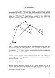
Horn mechanism) (Figure 1). For <strong>the</strong> sake <strong>of</strong> simplicity,<br />
<strong>the</strong> <strong>face</strong> section is approximated as being rectangular;<br />
<strong>the</strong> prism opposite <strong>the</strong> <strong>face</strong>, which is free to slide, can<br />
allow <strong>the</strong> upper parallelepiped to move vertically <strong>and</strong><br />
produce <strong>the</strong> so-called “rise” effect, which has obvious<br />
repercussions on <strong>the</strong> ground sur<strong>face</strong>. Indeed, in <strong>the</strong> case<br />
<strong>of</strong> <strong>shallow</strong> <strong>tunnels</strong>, <strong>excavation</strong>-<strong>face</strong> in<strong>stability</strong> can lead<br />
to <strong>the</strong> formation <strong>of</strong> a subsidence basin on <strong>the</strong> ground<br />
sur<strong>face</strong>. <strong>The</strong>re have been many cases in which accidents<br />
have occurred, sometimes ra<strong>the</strong>r serious ones, concerning<br />
existing buildings on <strong>the</strong> sur<strong>face</strong>, due to <strong>the</strong> impossibility<br />
<strong>of</strong> contrasting <strong>the</strong> <strong>face</strong>-in<strong>stability</strong> mechanism.<br />
<strong>The</strong> LEM is based on <strong>the</strong> following main hypo<strong>the</strong>ses:<br />
– <strong>the</strong> potentially unstable mass is represented by one<br />
or more monoliths that are considered infinitely<br />
rigid (undeformable), inside which failure cannot<br />
occur;<br />
– <strong>the</strong> kinematics <strong>of</strong> <strong>the</strong> block occurs due to sliding on<br />
simple sur<strong>face</strong>s known a priori as far as <strong>the</strong> shape<br />
<strong>and</strong> dimensions are concerned;<br />
– it is a static-type analysis, in that only <strong>the</strong> possibility<br />
<strong>of</strong> <strong>the</strong> initial displacement <strong>of</strong> <strong>the</strong> ground blocks is<br />
proved <strong>and</strong> <strong>the</strong> evolution <strong>of</strong> <strong>the</strong> potential in<strong>stability</strong><br />
phenomenon is not considered in any way whatsoever;<br />
– <strong>the</strong> possibility <strong>of</strong> ‘progressive failure’ occurring along<br />
<strong>the</strong> sliding sur<strong>face</strong>s is not taken into consideration.<br />
It is evident that <strong>the</strong> LEM is based on particular simplifications<br />
<strong>of</strong> <strong>the</strong> hypo<strong>the</strong>sised in<strong>stability</strong> mechanisms <strong>and</strong><br />
58. ACTA GEOTECHNICA SLOVENICA, 2011/2<br />
<strong>the</strong>refore requires that <strong>the</strong> results should be considered<br />
in a particularly critical manner. <strong>The</strong> use <strong>of</strong> <strong>the</strong> LEM in<br />
<strong>the</strong> analysis <strong>of</strong> many in<strong>stability</strong> mechanisms is, however,<br />
very common in <strong>the</strong> geotechnical <strong>and</strong> geomechanical<br />
fields, thanks to its simplicity, <strong>the</strong> intuitive nature <strong>of</strong> <strong>the</strong><br />
approach <strong>and</strong> <strong>the</strong> possibility <strong>of</strong> evaluating <strong>the</strong> degree <strong>of</strong><br />
<strong>stability</strong> through <strong>the</strong> safety factors.<br />
In order to evaluate <strong>the</strong> <strong>stability</strong> condition <strong>of</strong> <strong>the</strong> <strong>face</strong>,<br />
it is necessary to define <strong>the</strong> resisting (limit equilibrium<br />
condition) <strong>and</strong> <strong>the</strong> active forces on <strong>the</strong> instable ground<br />
zone so that <strong>the</strong>ir ratio can be computed along <strong>the</strong><br />
potentially feasible displacement direction. This implies<br />
a set <strong>of</strong> logical operations:<br />
1) identification <strong>of</strong> <strong>the</strong> geometry <strong>of</strong> <strong>the</strong> possible unstable<br />
ground zones, varying <strong>the</strong> slope angle ϑ;<br />
2) evaluation <strong>of</strong> <strong>the</strong>ir geometry (vertexes, volume <strong>and</strong><br />
areas <strong>of</strong> <strong>the</strong> unstable ground zones);<br />
3) computation <strong>of</strong> <strong>the</strong> resultants <strong>of</strong> <strong>the</strong> volume <strong>and</strong><br />
sur<strong>face</strong> forces acting on <strong>the</strong> unstable zones;<br />
4) evaluation <strong>of</strong> <strong>the</strong> resisting forces;<br />
5) static analysis, that is, computation <strong>of</strong> <strong>the</strong> safety<br />
factor or <strong>of</strong> <strong>the</strong> force that induces <strong>the</strong> limiting equilibrium<br />
condition.<br />
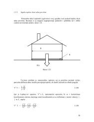
In <strong>the</strong> specific case under examination (Figure 2), block<br />
1 (a triangular prism) is enclosed by <strong>the</strong> planes 1, 2 <strong>and</strong><br />
3 <strong>and</strong> by <strong>the</strong> parallel planes a <strong>and</strong> d, on which <strong>the</strong> triangular<br />
bases rest. Plane 2 represents <strong>the</strong> sliding sur<strong>face</strong>.<br />
Block 2 is instead enclosed by planes 3, 4 <strong>and</strong> 5, by <strong>the</strong><br />
parallel planes b <strong>and</strong> e, <strong>and</strong> by <strong>the</strong> ground sur<strong>face</strong>.<br />
<strong>The</strong> vertical force V that block 2 applies to block 1 is<br />
given by <strong>the</strong> weight <strong>of</strong> block 2, by <strong>the</strong> possible pressure<br />
applied to <strong>the</strong> sur<strong>face</strong> <strong>and</strong> by <strong>the</strong> strength that<br />
Figure 1. a) <strong>The</strong> Horn mechanism used for <strong>the</strong> analysis <strong>of</strong> <strong>the</strong> <strong>stability</strong> <strong>of</strong> <strong>the</strong> <strong>excavation</strong> <strong>face</strong> [3];b) longitudinal section with <strong>the</strong> two<br />
blocks <strong>of</strong> ground (block 1 is prismatic <strong>and</strong> block 2 parallelepiped) under <strong>the</strong> hypo<strong>the</strong>sis <strong>of</strong> failure <strong>of</strong> <strong>the</strong> <strong>face</strong> in a sur<strong>face</strong> tunnel; c)<br />
admissible kinematics, for <strong>the</strong> two identified blocks, during failure <strong>of</strong> <strong>the</strong> <strong>excavation</strong> <strong>face</strong>. Key: V <strong>and</strong> H: forces that block 2 applies to<br />
block 1; ϑ: angle that is formed between <strong>the</strong> sliding sur<strong>face</strong> <strong>of</strong> block 1 <strong>and</strong> <strong>the</strong> horizontal plain; z: depth from <strong>the</strong> ground sur<strong>face</strong>;<br />
H t: height <strong>of</strong> <strong>the</strong> tunnel; h c: depth <strong>of</strong> <strong>the</strong> tunnel crown from <strong>the</strong> ground sur<strong>face</strong>.
can develop on <strong>the</strong> lateral sur<strong>face</strong>s <strong>of</strong> this block at <strong>the</strong><br />
moment in which it tends to move downwards:<br />
æB⋅Htö '<br />
æ Ht<br />
ö<br />
V = W2 + q⋅ ç<br />
÷ ( c snm , ,2 tanj) 2 çB<br />
÷<br />
ç<br />
- + ⋅ ⋅ ⋅ + ⋅hc<br />
è<br />
÷ ÷<br />
tanJ÷ ø è ç tanJ÷<br />
;<br />
ø<br />
V ≥ 0<br />
(1)<br />
æB⋅Htö where: W2 : <strong>the</strong> weight <strong>of</strong> block 2: W2= g ⋅ ç<br />
÷<br />
çè<br />
÷ ⋅hc<br />
tanJ<br />
÷ ø<br />
γ : <strong>the</strong> specific weight <strong>of</strong> <strong>the</strong> ground;<br />
q : <strong>the</strong> load applied to <strong>the</strong> ground sur<strong>face</strong>;<br />
B <strong>and</strong> H t: <strong>the</strong> width <strong>and</strong> height <strong>of</strong> <strong>the</strong> <strong>excavation</strong> <strong>face</strong>;<br />
ϑ: <strong>the</strong> inclination <strong>of</strong> plane 2 with respect to <strong>the</strong><br />
horizontal;<br />
c <strong>and</strong> φ: cohesion <strong>and</strong> friction angle inside <strong>the</strong> ground,<br />
adopting <strong>the</strong> Mohr-Coulomb failure criterion;<br />
σ n,m,2 : <strong>the</strong> mean normal effective stress on <strong>the</strong> lateral<br />
sur<strong>face</strong>s <strong>of</strong> block 2.<br />
V is only considered when positive; if it is negative, it is<br />
made equal to 0 so as not to consider <strong>the</strong> possibility that<br />
block 1 is hanging from block 2.<br />
<strong>The</strong> horizontal force H that block 2 applies to block 1 in<br />
correspondence to plane 3 is produced from <strong>the</strong> shear<br />
strength <strong>of</strong> <strong>the</strong> ground that can develop when a relative<br />
horizontal displacement between block 1 <strong>and</strong> block 2<br />
occurs:<br />
é æB⋅Htöù æB⋅Htö H = êV-u3⋅ ç<br />
÷ ú tanj<br />
c ç ÷<br />
ç<br />
⋅ + ⋅<br />
è<br />
÷ ç ÷<br />
tanJ÷ ø çètanJ÷<br />
; H ≥ 0 (2)<br />
êë úû<br />
ø<br />
where:<br />
Figure 2. Longitudinal section <strong>of</strong> <strong>the</strong> zone close to <strong>the</strong> <strong>excavation</strong> <strong>face</strong>, with <strong>the</strong> scheme <strong>of</strong><br />
<strong>the</strong> geometry adopted in <strong>the</strong> simplified analysis <strong>of</strong> <strong>the</strong> <strong>face</strong> <strong>stability</strong>.<br />
u 3: <strong>the</strong> mean pore pressure <strong>of</strong> <strong>the</strong> underground water in<br />
correspondence to plane 3.<br />
P. ORESTE: THE STABILITY OF THE EXCAVATION FACE OF SHALLOW CIVIL AND MINING TUNNELS<br />
H = 0 is also given for H < 0.<br />
Block 1, in incipient movement conditions, is also<br />
subject to two o<strong>the</strong>r forces, due to <strong>the</strong> shear strength <strong>of</strong><br />
<strong>the</strong> ground, which act in <strong>the</strong> direction <strong>of</strong> <strong>the</strong> displacement<br />
vector, but in an opposite versus to it: force R 2<br />
on <strong>the</strong> sliding sur<strong>face</strong> (eq.3) <strong>and</strong> force R a on <strong>the</strong> lateral<br />
planes a (eq.3):<br />
æB⋅Htö R2 = é( W1 V) cosJ ( H X1) sinJ Uù tanj<br />
c ç ÷<br />
ë<br />
+ ⋅ + - ⋅ -<br />
û<br />
⋅ + ⋅<br />
çèç ÷<br />
sinJ<br />
ø ÷ ;<br />
R2 ≥ 0 (3)<br />
where:<br />
2 æ H ö t<br />
W1: <strong>the</strong> weight <strong>of</strong> block 1: W1= g ⋅ ç ÷ ÷⋅ B<br />
ç è2⋅tanJ ÷ ø<br />
X1: <strong>the</strong> horizontal filtration force in block 1, due to<br />
<strong>the</strong> movement <strong>of</strong> <strong>the</strong> underground water, if present,<br />
towards <strong>the</strong> <strong>excavation</strong> <strong>face</strong>;<br />
U: <strong>the</strong> hydraulic under thrust force on <strong>the</strong> sliding<br />
sur<strong>face</strong>:<br />
æB⋅Htö U = u2⋅<br />
ç ÷<br />
çè<br />
÷<br />
sinJ<br />
÷<br />
; (4)<br />
ø<br />
u2: mean pressure <strong>of</strong> <strong>the</strong> underground water on<br />
plane 2.<br />
' ( )<br />
2 æ H ö t ÷<br />
Ra = c+ sn, m, ad⋅tanj<br />
⋅2⋅ ç ÷<br />
ç è2⋅tanJ ÷ ø ; Ra ≥ 0 (5)<br />
where:<br />
σn,m,ad : <strong>the</strong> mean normal effective stress on <strong>the</strong> lateral<br />
sur<strong>face</strong>s a <strong>of</strong> block 1.<br />
A more detailed study <strong>of</strong> <strong>the</strong> effect <strong>of</strong> <strong>the</strong> groundwater<br />
filtration on <strong>the</strong> static <strong>of</strong> <strong>the</strong> <strong>excavation</strong> <strong>face</strong> was developed<br />
by Oreste [4].<br />
ACTA GEOTECHNICA SLOVENICA, 2011/2 59.
P. ORESTE: THE STABILITY OF THE EXCAVATION FACE OF SHALLOW CIVIL AND MINING TUNNELS<br />
Once <strong>the</strong> forces acting on block 1 have been determined<br />
(W 1, V, H, R 2 , R ad , <strong>and</strong> X 1), it is possible to determine<br />
<strong>the</strong> safety factor in <strong>the</strong> function <strong>of</strong> <strong>the</strong> angle ϑ:<br />
F<br />
s,<br />
J<br />
R2+ Rad + H⋅cosJ<br />
=<br />
( W + V) ⋅ sinJ+ X ⋅cos<br />
J<br />
1 1<br />
60. ACTA GEOTECHNICA SLOVENICA, 2011/2<br />
(6)<br />
where <strong>the</strong> forces that oppose <strong>the</strong> sliding <strong>of</strong> block 1<br />
appear in <strong>the</strong> numerator, i.e., <strong>the</strong> forces mobilized by <strong>the</strong><br />
ground strength on sur<strong>face</strong>s 2 (sliding sur<strong>face</strong>) <strong>and</strong> on<br />
planes a, <strong>and</strong> <strong>the</strong> component H parallel to plane 2;<br />
while <strong>the</strong> forces that tend to induce sliding, i.e., <strong>the</strong><br />
components parallel to sur<strong>face</strong> 2 <strong>of</strong> <strong>the</strong> forces W 1, V <strong>and</strong><br />
X 1, appear in <strong>the</strong> denominator.<br />
As <strong>the</strong> angle ϑ <strong>of</strong> <strong>the</strong> potential sliding sur<strong>face</strong> is not<br />
known a priori, <strong>the</strong> minimum value <strong>of</strong> F s,ϑ is assumed<br />
for ϑ variables from 0 to 90° as <strong>the</strong> safety factor F s :<br />
= é ù<br />
ë û<br />
(7)<br />
Fs min Fs, J J= 0¸90 3 FIBREGLASS-REINFORCEMENT<br />
SYSTEM AT THE EXCAVATION<br />
FACE<br />
<strong>The</strong> reinforcement <strong>of</strong> <strong>the</strong> ground core at <strong>the</strong> <strong>excavation</strong><br />
<strong>face</strong> with fibreglass elements in <strong>shallow</strong> <strong>tunnels</strong> has <strong>the</strong><br />
main purpose <strong>of</strong> increasing <strong>the</strong> ground strength; this, as<br />
a consequence, leads to <strong>the</strong> <strong>stability</strong> <strong>of</strong> both <strong>the</strong> <strong>excavation</strong><br />
<strong>face</strong> itself <strong>and</strong> <strong>of</strong> <strong>the</strong> ground sur<strong>face</strong>, even when<br />
excavating large <strong>tunnels</strong> in poor or very poor ground<br />
(Figures 3 <strong>and</strong> 4).<br />
<strong>The</strong> technique consists <strong>of</strong> inserting sub-horizontal<br />
fibreglass dowels into <strong>the</strong> core ahead <strong>of</strong> <strong>the</strong> <strong>excavation</strong><br />
<strong>face</strong>. <strong>The</strong>se dowels are connected in a continuous way to<br />
<strong>the</strong> surrounding ground through <strong>the</strong> injection <strong>of</strong> mortar<br />
in <strong>the</strong> boreholes; <strong>the</strong>y <strong>the</strong>refore act in a traction <strong>and</strong><br />
shear dominion <strong>and</strong> have no external constraint system.<br />
<strong>The</strong> reinforcement elements are <strong>the</strong>n demolished during<br />
<strong>excavation</strong>.<br />
<strong>The</strong> use <strong>of</strong> this reinforcement system has become very<br />
common in recent years with a tendency <strong>of</strong> advancing<br />
using a full <strong>face</strong> <strong>excavation</strong> even in difficult geotechnical<br />
conditions. Fibreglass elements (generally hollow bars<br />
with an external diameter <strong>of</strong> 60 mm <strong>and</strong> a thickness <strong>of</strong><br />
about 20 mm or filled bars <strong>of</strong> various types) are characterised<br />
by high degrees <strong>of</strong> strength <strong>and</strong> low levels <strong>of</strong> specific<br />
weight, but also by a remarkable fragility that makes<br />
it possible to carry out <strong>the</strong> <strong>excavation</strong> with traditional<br />
ground-<strong>excavation</strong> machines, without any particular<br />
problems for <strong>the</strong> tools. <strong>The</strong> fibreglass pipes are produced<br />
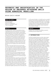
Figure 3. Example <strong>of</strong> <strong>face</strong> reinforcement in a <strong>shallow</strong> tunnel<br />
using longitudinal fibreglass pipes (Avigliana Tunnel, Turin,<br />
Italy): a) view <strong>of</strong> <strong>the</strong> <strong>face</strong> during <strong>the</strong> drilling stage; b) details <strong>of</strong><br />
<strong>the</strong> reinforcement intervention with <strong>the</strong> pipes already in place.<br />
with <strong>the</strong>rmo-hardening polyester resin, reinforced with<br />
glass fibres, whose content in weight is higher than 50 %.<br />
<strong>The</strong> reinforcement elements are usually arranged on<br />
<strong>the</strong> <strong>excavation</strong> <strong>face</strong> in concentric circles, with a certain<br />
regularity, trying to maintain a constant density as <strong>the</strong><br />
distance from <strong>the</strong> centre <strong>of</strong> <strong>the</strong> section changes.<br />
<strong>The</strong> intervention is marked by a high flexibility (its characteristics<br />
can easily change during advancement without<br />
<strong>the</strong> necessity <strong>of</strong> having to change machines) <strong>and</strong> an<br />
operative simplicity. However, this intervention requires<br />
that <strong>the</strong> <strong>excavation</strong> operations should be stopped for a<br />
few days in large <strong>tunnels</strong> <strong>and</strong> in <strong>the</strong> presence <strong>of</strong> a high<br />
density <strong>of</strong> reinforcements.<br />
<strong>The</strong> dimensioning <strong>of</strong> <strong>the</strong> intervention should be able to<br />
define <strong>the</strong> most important geometric parameters: <strong>the</strong><br />
number, <strong>the</strong> length <strong>and</strong> <strong>the</strong> section <strong>of</strong> <strong>the</strong> elements that<br />
it is necessary to use to make <strong>the</strong> <strong>excavation</strong> <strong>face</strong> stable,<br />
a)<br />
b)
a)<br />
b)<br />
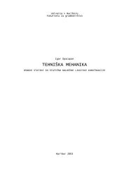
Figure 4. Typical scheme <strong>of</strong> a <strong>face</strong>-reinforcement intervention<br />
using longitudinal fibreglass elements: a) longitudinal section;<br />
b) transversal section [5]. A large number <strong>of</strong> elements, which<br />
are placed divergent from <strong>the</strong> tunnel axis, are <strong>of</strong>ten concentrated<br />
around <strong>the</strong> perimeter <strong>of</strong> <strong>the</strong> <strong>face</strong> to allow a crown <strong>of</strong><br />
ground around <strong>the</strong> tunnel to be reinforced.<br />
with an adequate safety margin. It is just as important to<br />
define <strong>the</strong> minimum residual length that <strong>the</strong> elements<br />
can have at <strong>the</strong> end <strong>of</strong> <strong>the</strong> advancement stage, before<br />
proceeding with <strong>the</strong> reinforcement <strong>of</strong> a subsequent tract.<br />
4 SIMPLIFIED ANALYSIS<br />
METHODS TO EVALUATE THE<br />
ACTION OF REINFORCEMENTS<br />
<strong>The</strong> reinforcement <strong>of</strong> <strong>the</strong> ground at <strong>the</strong> <strong>excavation</strong><br />
<strong>face</strong> in sur<strong>face</strong> <strong>tunnels</strong> is at present <strong>of</strong>ten dimensioned<br />
through simplified approaches. <strong>The</strong> number <strong>and</strong> <strong>the</strong><br />
type <strong>of</strong> <strong>the</strong> reinforcement elements is defined in an<br />
empirical manner, in an analogous way to similar cases<br />
in which <strong>the</strong> intervention was performed successfully,<br />
or using simplified analytical formulas. Recourse to<br />
numerical calculations that are able to simulate in detail<br />
each reinforcement element <strong>and</strong> each construction<br />
stage <strong>of</strong> <strong>the</strong> tunnel is still rare outside research practice;<br />
a tri-dimensional numerical modelling with very small<br />
model elements in order to be able to precisely capture<br />
<strong>the</strong> reinforcement-ground interaction, <strong>and</strong> also <strong>the</strong><br />
simulation <strong>of</strong> each single <strong>excavation</strong> <strong>and</strong> support stage <strong>of</strong><br />
<strong>the</strong> tunnel are in fact required. All <strong>the</strong>se aspects make an<br />
adequate numerical calculation complex <strong>and</strong> not suitable<br />
for <strong>the</strong> parametric analyses that are necessary to obtain a<br />
correct dimensioning <strong>of</strong> a reinforcement intervention.<br />
Empirical methods are mainly based on acquired experience<br />
in <strong>the</strong> construction <strong>of</strong> structures with characteristics<br />
P. ORESTE: THE STABILITY OF THE EXCAVATION FACE OF SHALLOW CIVIL AND MINING TUNNELS<br />
similar to those <strong>of</strong> <strong>the</strong> project or on experimental models<br />
set up in <strong>the</strong> laboratory, which reproduce <strong>the</strong> phenomenon<br />
under examination, though on a reduced scale.<br />
An application <strong>of</strong> <strong>the</strong>se methods, which is very common<br />
<strong>and</strong> has been well tested for structures both in rock <strong>and</strong><br />
in ground, is that <strong>of</strong> <strong>the</strong> use <strong>of</strong> technical classifications<br />
which, however, consider <strong>the</strong> overall <strong>stability</strong> <strong>of</strong> <strong>the</strong> void<br />
<strong>and</strong> do not generally deal with <strong>the</strong> problem <strong>of</strong> <strong>the</strong> <strong>stability</strong><br />
<strong>of</strong> <strong>the</strong> <strong>excavation</strong> <strong>face</strong> in a specific way.<br />
Broms <strong>and</strong> Bennermark [6], on <strong>the</strong> basis <strong>of</strong> observations<br />
<strong>of</strong> real cases <strong>and</strong> laboratory tests that consisted<br />
in extruding clayey materials through a circular hole,<br />
revealed that <strong>the</strong> <strong>stability</strong> conditions <strong>of</strong> <strong>the</strong> <strong>excavation</strong><br />
<strong>face</strong> are guaranteed if <strong>the</strong> <strong>stability</strong> index N f is lower than<br />
6-7, where N f is equal to:<br />
where:<br />
N<br />
f<br />
sv - p f<br />
= (8)<br />
c<br />
σ v : <strong>the</strong> vertical stress at <strong>the</strong> depth <strong>of</strong> <strong>the</strong> centre <strong>of</strong> <strong>the</strong><br />
<strong>excavation</strong> <strong>face</strong>;<br />
p f : <strong>the</strong> pressure applied to <strong>the</strong> <strong>excavation</strong> <strong>face</strong>;<br />
c u : <strong>the</strong> undrained shear strength.<br />
u<br />
Kimura <strong>and</strong> Mair [7], on <strong>the</strong> basis <strong>of</strong> centrifuge tests on<br />
clay reconsolidated in <strong>the</strong> laboratory, obtained values<br />
<strong>of</strong> <strong>the</strong> N f index between 5 <strong>and</strong> 10 for <strong>the</strong> condition <strong>of</strong><br />
<strong>stability</strong> <strong>of</strong> <strong>the</strong> <strong>excavation</strong> <strong>face</strong> <strong>and</strong> were able to demonstrate<br />
<strong>the</strong> marked dependence <strong>of</strong> N f on <strong>the</strong> depth.<br />
<strong>The</strong> reinforcement elements should <strong>the</strong>refore be able<br />
to guarantee <strong>the</strong> development <strong>of</strong> a fictitious pressure p f<br />
(<strong>and</strong> <strong>the</strong>refore <strong>of</strong> a force S that is equal to such a pressure<br />
multiplied by <strong>the</strong> <strong>excavation</strong> <strong>face</strong> area A f) so as to obtain<br />
an index N f that is lower than 6-7, with a certain margin<br />
<strong>of</strong> safety.<br />
It is also possible to obtain <strong>the</strong> horizontal force S that is<br />
necessary to apply to <strong>the</strong> <strong>excavation</strong> <strong>face</strong> to obtain <strong>the</strong><br />
required safety factor using <strong>the</strong> LEM. Once <strong>the</strong> desired<br />
value <strong>of</strong> F s has been decided, <strong>the</strong> force H is back calculated<br />
from equations 3, 6 <strong>and</strong> 7 (H*). S is <strong>the</strong>n derived by<br />
<strong>the</strong> difference (H*- H), that is <strong>the</strong> difference between <strong>the</strong><br />
value <strong>of</strong> H obtained from <strong>the</strong> back analysis <strong>and</strong> <strong>the</strong> value<br />
<strong>of</strong> H calculated from eq. 2.<br />
Once <strong>the</strong> force S is known through empirical laws or<br />
using <strong>the</strong> LEM, <strong>the</strong> reinforcement elements can be<br />
simply dimensioned, hypo<strong>the</strong>sising that <strong>the</strong>y perform<br />
<strong>the</strong>ir static function only by developing an axial force on<br />
<strong>the</strong>ir inside (a hypo<strong>the</strong>sis <strong>of</strong> flexural stiffness nil <strong>of</strong> <strong>the</strong><br />
reinforcement system).<br />
ACTA GEOTECHNICA SLOVENICA, 2011/2 61.
P. ORESTE: THE STABILITY OF THE EXCAVATION FACE OF SHALLOW CIVIL AND MINING TUNNELS<br />
This hypo<strong>the</strong>sis makes it possible to limit <strong>the</strong> verification<br />
<strong>of</strong> <strong>the</strong> behaviour <strong>of</strong> <strong>the</strong> reinforcement elements to <strong>the</strong><br />
following three inequalities:<br />
S<br />
£ sadm<br />
⋅ Abar<br />
(9)<br />
n<br />
S<br />
£ tadm ⋅( p⋅fhole ⋅ La<br />
) (10)<br />
n<br />
S<br />
£ tadm ⋅( p⋅fhole ⋅ Lp<br />
) (11)<br />
n<br />
where:<br />
σ adm: <strong>the</strong> maximum allowed traction stress in <strong>the</strong><br />
fibreglass;<br />
τ adm: <strong>the</strong> maximum allowed shear stress at <strong>the</strong><br />
mortar-ground inter<strong>face</strong>;<br />
Φ hole: <strong>the</strong> diameter <strong>of</strong> <strong>the</strong> hole;<br />
L a: <strong>the</strong> length <strong>of</strong> <strong>the</strong> dowel in prismatic block 1;<br />
L p: <strong>the</strong> length <strong>of</strong> <strong>the</strong> dowel in <strong>the</strong> stable portion <strong>of</strong><br />
<strong>the</strong> ground;<br />
n: <strong>the</strong> number <strong>of</strong> dowels foreseen at <strong>the</strong> <strong>excavation</strong><br />
<strong>face</strong>;<br />
A bar: section area <strong>of</strong> each single element.<br />
It is possible to define A bar , L a , L p <strong>and</strong> n from equations<br />
9-11, though not in a univocal manner.<br />
5 DETAILED ANALYSIS OF THE<br />
GROUND-DOWEL INTERACTION<br />
In order to perform an accurate analysis <strong>of</strong> <strong>the</strong> grounddowels<br />
interaction, a new analytical formulation is<br />
presented in <strong>the</strong> following; it is able to provide a reasonable<br />
evaluation <strong>of</strong> <strong>the</strong> behaviour <strong>of</strong> a single dowel <strong>and</strong> it<br />
also allows a quick dimensioning <strong>of</strong> <strong>the</strong> reinforcement<br />
system.<br />
<strong>The</strong> unknown factors are <strong>the</strong> global forces (axial N, shear<br />
T <strong>and</strong> bending M stresses) that develop along <strong>the</strong> dowels<br />
<strong>and</strong> which are functions <strong>of</strong> a small dislocation displacement<br />
<strong>of</strong> <strong>the</strong> potentially unstable block.<br />
<strong>The</strong> design <strong>of</strong> <strong>the</strong> dowels can take place through a<br />
sequence <strong>of</strong> trials, assuming different reinforcement<br />
schemes, until <strong>the</strong> safety factor <strong>of</strong> <strong>the</strong> potentially<br />
unstable block at <strong>the</strong> <strong>excavation</strong> <strong>face</strong> is higher than <strong>the</strong><br />
minimum allowed value.<br />
After having defined <strong>the</strong> safety factor <strong>of</strong> <strong>the</strong> <strong>excavation</strong><br />
<strong>face</strong> in its natural state (i.e., without reinforcement),<br />
according to <strong>the</strong> criteria reported in section 2, <strong>and</strong><br />
having verified <strong>the</strong> needs <strong>of</strong> reinforcement to increase<br />
<strong>the</strong> safety factor, <strong>the</strong> main stages <strong>of</strong> <strong>the</strong> design can be<br />
summarised as follows:<br />
62. ACTA GEOTECHNICA SLOVENICA, 2011/2<br />
a) definition <strong>of</strong> <strong>the</strong> chosen reinforcement scheme<br />
(number, position <strong>and</strong> dimensions <strong>of</strong> <strong>the</strong> dowels);<br />
b) assignment <strong>of</strong> a value to <strong>the</strong> angle ϑ;<br />
c) assignment <strong>of</strong> an arbitrary displacement δ to unstable<br />
block 1 along <strong>the</strong> sliding direction; evaluation <strong>of</strong> <strong>the</strong><br />
components <strong>of</strong> such a displacement-vector acting in<br />
<strong>the</strong> normal δ t <strong>and</strong> axial δ n dowel directions (Figure 5);<br />
d) based on δ t <strong>and</strong> δ n , evaluation <strong>of</strong> <strong>the</strong> shear force T, <strong>of</strong><br />
<strong>the</strong> bending moment M, <strong>of</strong> <strong>the</strong> axial tensile force N<br />
<strong>and</strong> <strong>of</strong> <strong>the</strong> relative dowel-rock displacement v r, induced<br />
along each dowel. In order to design <strong>the</strong> dowels<br />
<strong>and</strong> analyse <strong>the</strong> <strong>stability</strong> <strong>of</strong> <strong>the</strong> <strong>face</strong>, <strong>the</strong> values <strong>of</strong> T,<br />
N <strong>and</strong> M at <strong>the</strong> sliding sur<strong>face</strong> (plan 2) (where <strong>the</strong><br />
maximum values <strong>of</strong> <strong>the</strong> shear force <strong>and</strong> <strong>the</strong> traction<br />
axial force develop) are <strong>of</strong> particular importance;<br />
e) calculation <strong>of</strong> <strong>the</strong> “local” safety factors for failure<br />
<strong>of</strong> <strong>the</strong> bar <strong>and</strong> <strong>of</strong> <strong>the</strong> dowel-ground connection, for<br />
each dowel, on <strong>the</strong> basis <strong>of</strong> <strong>the</strong> values <strong>of</strong> T, N <strong>and</strong> M<br />
<strong>and</strong> <strong>of</strong> <strong>the</strong> displacements v r evaluated in d);<br />
f) evaluation <strong>of</strong> <strong>the</strong> ratio η between each calculated<br />
local safety factor <strong>and</strong> <strong>the</strong> corresponding previously<br />
imposed minimum allowable value;<br />
g) <strong>the</strong> minimum value <strong>of</strong> η for each local safety factor<br />
<strong>and</strong> each dowel at <strong>the</strong> <strong>face</strong>, multiplied by <strong>the</strong> arbitrary<br />
displacement δ applied to <strong>the</strong> block, represents<br />
<strong>the</strong> maximum displacement δ max that <strong>the</strong> unstable<br />
block can sustain before at least one <strong>of</strong> <strong>the</strong> local safety<br />
factors drops below its minimum allowable value;<br />
h) evaluation <strong>of</strong> <strong>the</strong> N <strong>and</strong> T forces in each single dowel<br />
at <strong>the</strong> sliding sur<strong>face</strong>, for a displacement <strong>of</strong> <strong>the</strong> block<br />
equal to δ max ; such forces represent <strong>the</strong> maximum<br />
contribution that each dowel can <strong>of</strong>fer to <strong>the</strong> <strong>stability</strong><br />
<strong>of</strong> <strong>the</strong> block;<br />
i) determination <strong>of</strong> <strong>the</strong> “global” safety factor <strong>of</strong> <strong>the</strong><br />
unstable block 1, considering <strong>the</strong> contribution <strong>of</strong> <strong>the</strong><br />
dowels, for <strong>the</strong> assigned value <strong>of</strong> ϑ;<br />
j) repetition <strong>of</strong> steps b)-i), increasing <strong>the</strong> value <strong>of</strong> ϑ at<br />
each cycle until ϑ =90°; <strong>the</strong> “global” safety factor <strong>of</strong><br />
<strong>the</strong> unstable block is obtained at each cycle for <strong>the</strong><br />
assigned value <strong>of</strong> ϑ;<br />
k) <strong>the</strong> minimum value <strong>of</strong> <strong>the</strong> obtained global safety<br />
factors is <strong>the</strong>n considered as <strong>the</strong> safety factor <strong>of</strong> <strong>the</strong><br />
reinforced <strong>excavation</strong> <strong>face</strong>; if this value is lower or<br />
much higher than <strong>the</strong> minimum allowable value,<br />
return to point a), change <strong>the</strong> reinforcement scheme<br />
<strong>and</strong> repeat <strong>the</strong> whole procedure until <strong>the</strong> reinforcement<br />
scheme that is suitable for stabilising <strong>the</strong> <strong>face</strong> is<br />
obtained.<br />
<strong>The</strong> detail <strong>of</strong> <strong>the</strong> proposed ma<strong>the</strong>matical procedure is<br />
developed in Oreste [4]. <strong>The</strong> global safety factor F s,ϑ <strong>of</strong><br />
<strong>the</strong> unstable block 1 must now be evaluated, taking into<br />
consideration <strong>the</strong> stabilising forces produced by each<br />
dowel (i=1÷n)
F<br />
s,<br />
J<br />
éæ ö æ ö ù<br />
R2 + Rad + H⋅ cosJ+ êç N ÷<br />
0, dmax , i ÷ ⋅ cosJ+ ç T ÷<br />
0, dmax<br />
, i ÷ ⋅sin<br />
Jú<br />
ê ç çå ÷<br />
ç çå<br />
èi=¸ 1 n ø è<br />
÷ ú<br />
i=¸ 1 n ø<br />
=<br />
ë û<br />
( W + V) ⋅ sinJ+ X ⋅cos<br />
J<br />
1 1<br />
where R 2 is now given by <strong>the</strong> following expression, which substitutes eq. 3:<br />
éæ ö æ ö ù æB⋅Htö R2= êçW1+ V- T ÷<br />
0, dmax , i÷ ⋅ cosJ+ çH-<br />
X1+ N ÷<br />
0, dmax<br />
, i÷<br />
⋅sinJ-Uú ⋅ tanj+<br />
c⋅ç<br />
÷<br />
ê ç å ÷<br />
ç å ç ÷<br />
è<br />
÷ ú ç<br />
i=¸ 1 n ø è ÷<br />
è i=¸ 1 n ø<br />
sinJ<br />
÷ ; R<br />
ø 2≥0 (13)<br />
ë û<br />
where N0 ,δmax <strong>and</strong> T0 ,δmax are <strong>the</strong> axial force <strong>and</strong> shear force in <strong>the</strong> dowel at <strong>the</strong> dowel-sliding sur<strong>face</strong> intersection when<br />
δ=δmax .<br />
Figure 5. Breakdown <strong>of</strong> <strong>the</strong> displacement δ imposed on block<br />
1. Key: δ displacement <strong>of</strong> block 1 along <strong>the</strong> sliding direction; δ n<br />
<strong>and</strong> δ t components <strong>of</strong> <strong>the</strong> displacement in <strong>the</strong> axial <strong>and</strong> normal<br />
directions <strong>of</strong> <strong>the</strong> dowel; L a length <strong>of</strong> <strong>the</strong> dowel in <strong>the</strong> ground<br />
block 1 (zone I); L p length <strong>of</strong> <strong>the</strong> remaining part <strong>of</strong> <strong>the</strong> dowel<br />
in <strong>the</strong> stable ground (zone II); x axial coordinate; ϑ: angle<br />
between <strong>the</strong> sliding direction <strong>and</strong> <strong>the</strong> horizontal plane; A, B,<br />
<strong>and</strong> D vertices <strong>of</strong> ground block 1.<br />
P. ORESTE: THE STABILITY OF THE EXCAVATION FACE OF SHALLOW CIVIL AND MINING TUNNELS<br />
(12)<br />
<strong>The</strong> presence <strong>of</strong> <strong>the</strong> dowels obviously induces an<br />
increase in <strong>the</strong> safety-factor value in relation to <strong>the</strong> characteristics<br />
<strong>of</strong> <strong>the</strong> chosen reinforcement system.<br />
<strong>The</strong> calculations developed in steps b)-i) are repeated<br />
for different values <strong>of</strong> ϑ, increasing it at each cycle, for<br />
example by 5°, until ϑ=90° is reached; at each cycle <strong>the</strong><br />
“global” safety factor <strong>of</strong> <strong>the</strong> unstable block 1 is obtained<br />
for <strong>the</strong> assigned value <strong>of</strong> ϑ. <strong>The</strong> safety factor <strong>of</strong> <strong>the</strong> reinforced<br />
<strong>excavation</strong> <strong>face</strong> is <strong>the</strong>refore <strong>the</strong> minimum value <strong>of</strong><br />
<strong>the</strong> obtained F s,ϑ.<br />
If <strong>the</strong> increase in <strong>the</strong> safety factor <strong>of</strong> <strong>the</strong> <strong>face</strong> due to <strong>the</strong><br />
reinforcement system is still not sufficient, or when it is<br />
considered excessive, it is necessary to modify <strong>the</strong> reinforcement<br />
scheme on <strong>the</strong> basis <strong>of</strong> <strong>the</strong> obtained results<br />
<strong>and</strong> to repeat <strong>the</strong> procedure from stage a) to stage k).<br />
Figure 6. Example <strong>of</strong> <strong>the</strong> procedure for <strong>the</strong> determination <strong>of</strong> <strong>the</strong> number <strong>and</strong> <strong>the</strong> minimum length <strong>of</strong> <strong>the</strong> reinforcements at <strong>the</strong> <strong>face</strong>.<br />
Each line <strong>of</strong> <strong>the</strong> graph refers to a different length <strong>of</strong> <strong>the</strong> dowels at <strong>the</strong> <strong>excavation</strong> <strong>face</strong><br />
ACTA GEOTECHNICA SLOVENICA, 2011/2 63.
P. ORESTE: THE STABILITY OF THE EXCAVATION FACE OF SHALLOW CIVIL AND MINING TUNNELS<br />
<strong>The</strong> dimensioning <strong>of</strong> <strong>the</strong> intervention is generally<br />
limited to a definition <strong>of</strong> <strong>the</strong> number <strong>of</strong> reinforcements<br />
<strong>and</strong> <strong>the</strong>ir minimal residual length. <strong>The</strong> total length <strong>of</strong><br />
each reinforcement is subsequently identified by <strong>the</strong><br />
maximum length that can be obtained without deviations<br />
<strong>of</strong> <strong>the</strong> hole. From <strong>the</strong> proposed procedure it is<br />
possible to obtain a summarizing graph (<strong>the</strong> results <strong>of</strong> a<br />
calculation example are shown in Figure 6) in which <strong>the</strong><br />
safety factors <strong>of</strong> <strong>the</strong> <strong>face</strong> are reported with a variation in<br />
<strong>the</strong> number <strong>of</strong> reinforcements <strong>and</strong> <strong>the</strong>ir length (which<br />
should be intended as <strong>the</strong> minimum residual length).<br />
After having fixed <strong>the</strong> desired safety factor (1.2 in <strong>the</strong><br />
example <strong>of</strong> Figure 6), it is possible to define <strong>the</strong> necessary<br />
intervention scheme: 80 dowels with a minimum<br />
residual length <strong>of</strong> 7 m, or 110 dowels with a minimum<br />
residual length <strong>of</strong> 6 m, or even 140 dowels with a<br />
minimum residual length <strong>of</strong> 5 m. <strong>The</strong> total length <strong>of</strong> <strong>the</strong><br />
reinforcements does not usually exceed 22 m.<br />
Two real cases, both <strong>of</strong> which occurred in <strong>the</strong> North-<br />
West <strong>of</strong> Italy, in which failure <strong>of</strong> <strong>the</strong> <strong>excavation</strong> <strong>face</strong><br />
occurred in s<strong>and</strong>y quartzite grounds <strong>of</strong> medium to<br />
coarse size, were studied by applying <strong>the</strong> proposed<br />
calculation method. <strong>The</strong> examined <strong>tunnels</strong>, <strong>of</strong> polycentric<br />
shape <strong>and</strong> areas <strong>of</strong> about 104 m 2 , belong to <strong>the</strong> same<br />
zone in <strong>the</strong> Province <strong>of</strong> Biella (Italy). In both cases, loose<br />
s<strong>and</strong> formations (arkose s<strong>and</strong>s) derived from <strong>the</strong> decay<br />
<strong>of</strong> <strong>the</strong> rocky granite substratum were being crossed. <strong>The</strong><br />
reinforcement scheme at <strong>the</strong> <strong>excavation</strong> <strong>face</strong> in both<br />
cases foresaw <strong>the</strong> use <strong>of</strong> 40 injected fibreglass pipes with<br />
a total length <strong>of</strong> 14 m, 5 m <strong>of</strong> which were overlapping.<br />
<strong>The</strong> hole diameter (Ф hole) was 150 mm. <strong>The</strong> <strong>tunnels</strong> were<br />
full section excavated.<br />
In <strong>the</strong> first case a sliding <strong>of</strong> <strong>the</strong> <strong>face</strong> occurred during<br />
<strong>the</strong> <strong>excavation</strong> in correspondence to <strong>the</strong> second steel<br />
set after having realised <strong>the</strong> reinforcement phase (<strong>the</strong><br />
residual length <strong>of</strong> <strong>the</strong> dowels at <strong>the</strong> <strong>face</strong> was <strong>the</strong>refore 12<br />
m), when <strong>the</strong> overburden was about 10 m.<br />
In <strong>the</strong> second case <strong>the</strong> collapse occurred when <strong>the</strong><br />
residual length <strong>of</strong> <strong>the</strong> dowels at <strong>the</strong> <strong>face</strong> was 10 m. <strong>The</strong><br />
overburden on <strong>the</strong> crown, at <strong>the</strong> moment <strong>of</strong> <strong>the</strong> failure,<br />
was about 5 m.<br />
From <strong>the</strong> results obtained using <strong>the</strong> proposed calculation<br />
method it was possible to see how <strong>the</strong> safety factor<br />
<strong>of</strong> <strong>the</strong> <strong>excavation</strong> <strong>face</strong> in both cases is slightly lower<br />
than unity <strong>and</strong> this justifies <strong>the</strong> failures that occurred.<br />
<strong>The</strong>se results make it possible to confirm <strong>the</strong> causes <strong>of</strong><br />
<strong>the</strong> previously identified events (insufficient drainage<br />
system <strong>and</strong> an imperfect construction <strong>of</strong> <strong>the</strong> pre-support<br />
structure) <strong>and</strong> also to validate <strong>the</strong> proposed calculation<br />
procedure.<br />
64. ACTA GEOTECHNICA SLOVENICA, 2011/2<br />
6 CONCLUSIONS<br />
<strong>The</strong> problem <strong>of</strong> <strong>excavation</strong>-<strong>face</strong> <strong>stability</strong> in sur<strong>face</strong><br />
<strong>tunnels</strong> in poor ground currently represents one <strong>of</strong> <strong>the</strong><br />
most interesting challenges in <strong>the</strong> tunnel sector. Cases<br />
in which <strong>the</strong> <strong>excavation</strong> <strong>face</strong>s collapse in spite <strong>of</strong> <strong>the</strong> fact<br />
that <strong>the</strong>y have previously been reinforced with fibreglass<br />
dowels are in fact not so rare. A new calculation procedure<br />
for <strong>the</strong> analysis <strong>of</strong> reinforcement interventions<br />
using fibreglass dowels at <strong>the</strong> <strong>excavation</strong> <strong>face</strong> in sur<strong>face</strong><br />
<strong>tunnels</strong> has been illustrated in this paper. <strong>The</strong> procedure,<br />
which is based on <strong>the</strong> limit-equilibrium method applied<br />
to <strong>the</strong> ground core ahead <strong>of</strong> <strong>the</strong> <strong>excavation</strong> <strong>face</strong>, is able<br />
to evaluate, in detail, <strong>the</strong> interaction between each<br />
reinforcement element <strong>and</strong> <strong>the</strong> surrounding ground <strong>and</strong><br />
it permits <strong>the</strong> maximum static contribution that each<br />
reinforcement element is able to give to <strong>the</strong> <strong>stability</strong> <strong>of</strong><br />
<strong>the</strong> <strong>face</strong> to be determined.<br />
<strong>The</strong> calculation procedure has been applied to two real<br />
cases <strong>of</strong> tunnel-<strong>face</strong> collapse in <strong>the</strong> presence <strong>of</strong> fibreglass<br />
reinforcement intervention <strong>and</strong> <strong>the</strong> results show a safety<br />
factor just below unity for both cases, which is in agreement<br />
with <strong>the</strong> events that have occurred. This has made<br />
it possible, on <strong>the</strong> one h<strong>and</strong>, to consider <strong>the</strong> presented<br />
procedure reliable, <strong>and</strong> on <strong>the</strong> o<strong>the</strong>r, to confirm <strong>the</strong><br />
hypo<strong>the</strong>ses initially advanced concerning <strong>the</strong> causes <strong>of</strong><br />
<strong>the</strong> collapses.<br />
REFERENCES<br />
[1] Likar J. (2004). Back analysis <strong>of</strong> time-dependet<br />
displacement at <strong>the</strong> Trojane tunnel construction.<br />
Acta geotech. Slov., 1, 1, 21-36.<br />
[2] Likar J., Vesel G., Dervaric E. <strong>and</strong> Jeromel G.<br />
(2006). Time-dependent processes in rocks. RMZmater.<br />
geoenviron., 53, 3, 285-301.<br />
[3] Anagnostou G. <strong>and</strong> Kovari K. (1996). Face Stability<br />
Conditions with Earth-Pressure-Balanced<br />
Shields. Tunn.&Undergr. Space Techn., 11,<br />
165-173.<br />
[4] Oreste P. (2009). Face stabilisation <strong>of</strong> <strong>shallow</strong><br />
<strong>tunnels</strong> using fibreglass dowels. Proceedings <strong>of</strong><br />
ICE, Geotechnical Engineering, 162, 2, 95-109.<br />
[5] Lunardi, P. (2000). <strong>The</strong> design <strong>and</strong> construction <strong>of</strong><br />
<strong>tunnels</strong> using <strong>the</strong> approach based on <strong>the</strong> analysis <strong>of</strong><br />
controlled deformations in rocks <strong>and</strong> soils. http://<br />
www.rocksoil.com/p_d_f/t_<strong>and</strong>_t_rocksoil_supp.<br />
pdf.<br />
[6] Broms B.B. <strong>and</strong> Bennermark H. (1967). Stability<br />
<strong>of</strong> Clay at Vertical Openings. ASCE Journal <strong>of</strong> Soil<br />
Mech. <strong>and</strong> Found. Div, 93.
[7] Kimura T. <strong>and</strong> Mair J.R. (1981). Centrifugal Testing<br />
<strong>of</strong> Model Tunnels in S<strong>of</strong>t Clay. 10 th Int. Conf. <strong>of</strong><br />
Soil Mech. <strong>and</strong> Found. Eng., Stockolm (Sweden).<br />
P. ORESTE: THE STABILITY OF THE EXCAVATION FACE OF SHALLOW CIVIL AND MINING TUNNELS<br />
ACTA GEOTECHNICA SLOVENICA, 2011/2 65.