Direct Acting Pressure Reducing Valves - Filter
Direct Acting Pressure Reducing Valves - Filter
Direct Acting Pressure Reducing Valves - Filter

Create successful ePaper yourself
Turn your PDF publications into a flip-book with our unique Google optimized e-Paper software.
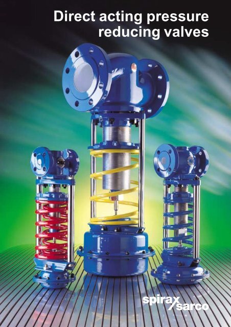
<strong>Direct</strong> acting pressure<br />
reducing valves
2<br />
<strong>Pressure</strong> control valves for steam, water<br />
and air mains distribution<br />
Spirax Sarco DRV control valves are specifically designed for<br />
the control of pressure within steam, water and air distribution<br />
mains which operate at pressures up to 40 bar g and<br />
temperatures up to 300°C.<br />
A NITRILE rubber soft seated option Type DRV-G is<br />
available for tight shut-off applications which do not<br />
exceed 90°C, a maximum pressure turndown ratio<br />
of 10:1 is recommended for optimum performance.<br />
Flow from under to over seat<br />
for improved control and longer life.<br />
Stainless steel metal / metal and<br />
NITRILE rubber soft seated options.<br />
Double guided stem for extended valve life.<br />
Balancing bellows provides high closing<br />
differential pressure and improved control.<br />
Spanner operated pressure setting plate<br />
which is light in operation and gives<br />
fine adjustment of downstream pressure.<br />
Bellows stem sealing for<br />
low maintenance and long life.<br />
Chrome vanadium springs, colour coded<br />
for setting range and total interchangeability.<br />
Spring plate with needle roller bearing which<br />
adds to ease of adjustment.<br />
<strong>Pressure</strong> chamber with fabric reinforced<br />
diaphragms for accuracy and sensitivity.<br />
Range of interchangeable actuators<br />
combined with 6 spring ranges<br />
to give maximum product flexibility.
Valve options<br />
Due to the diverse and often remote nature of distribution pipework, this modern range of products has retained<br />
the feature of being self-powered and therefore provides the major benefits of easy installation and a long, low<br />
maintenance life expectancy.<br />
Set pressures for the DRV cover a wide span of 0.1 to 20 bar g and are available for all DN15 to 100 valve sizes,<br />
with the option of SG iron or cast steel body materials.<br />
When the valves are used on steam which has a temperature in excess of 125°C, the pressure sensing line to the<br />
valve actuator passes through a water seal pot. This allows the use of a fabric reinforced EPDM diaphragm within<br />
the actuator, giving the benefit of greater sensitivity and control accuracy throughout the pressure control range.<br />
For applications where there is rapid fluctuation of pressures or loads the larger volume WS4 - 3 is available.<br />
Actuators are available with NITRILE rubber diaphragms for oil applications.<br />
Although designed for operating on saturated steam a small amount of superheat can be tolerated due to the<br />
cooling affect of the pressure signal line.<br />
The standard DRV has<br />
Water Research Council approval<br />
Certificate No. 9603028<br />
for primary use applications.<br />
Model Size Body material Connections*<br />
How it works<br />
On start-up, the valve is open allowing the medium to flow to the downstream system. Compression is applied<br />
to the control spring through the setting plate using a spanner. The power in the spring is transmitted through the<br />
spring plate to the valve push rod which holds the valve plug in the fully open position. As downstream pressure<br />
increases it acts through a pressure sensing line onto the diaphragm attached to the end of the valve push rod.<br />
Downstream pressure will continue to increase until the pressure acting on the diaphragm, overcomes spring<br />
pressure holding the valve plug in the open position, moving it towards the valve seat to modulate flow and<br />
maintain the required downstream pressure.<br />
An important feature in the operation of the valve<br />
is the use of a balancing bellows to eliminate the<br />
effect of differences in upstream and downstream<br />
pressure on the valve plug which can cause noise<br />
and vibration.<br />
Water seal pot type WS4<br />
<strong>Pressure</strong> ranges<br />
bar g<br />
DRV7<br />
DRV7G<br />
DN15 - 50 SG iron BSP / NPT<br />
✝ 0.1 -<br />
✝✝ 0.2 -<br />
0.6<br />
1.2<br />
300°C<br />
90°C<br />
DRV7<br />
DRV7G<br />
DN15 - 100 SG iron BS 4504 PN16 / 25<br />
0.8 -<br />
2.0 -<br />
2.5<br />
5.0<br />
300°C<br />
90°C<br />
DRV4<br />
DN15 - 100 Cast steel BS 4504 PN40<br />
4.5 - 10.0 300°C<br />
User benefits<br />
● Long life and reliable performance from the<br />
natural features of a self-powered unit.<br />
● Low installation costs through one trade fix.<br />
● Low maintenance costs<br />
from bellows sealing of the valve stem.<br />
● Accurate and stable control<br />
through the balancing bellows.<br />
Operating limits<br />
25 bar g<br />
25 bar g<br />
40 bar g<br />
DRV4G 8.0 - 20.0 90°C<br />
*ANSI and JIS flanges also available DN32 to DN50 range 0.15 - 0.6, DN65 to DN100 range 0.3 - 0.6 DN65 to DN100 range 0.4 - 1.2<br />
● Close setting of the desired pressure through the<br />
inclusion of fine actuator setting adjustment .<br />
● Simple on site pressure range changes due to<br />
totally interchangeable springs and actuators.<br />
● Safety where steam mains are subject to thermal<br />
shock. This is achieved by including in the range,<br />
PN25 SG (ductile) iron valves - DN15-100.<br />
● Flexibility of choice from a downstream pressure<br />
control range which spans 0.1 to 20 bar g.<br />
● Integrity of shut-off with tight soft seat option.<br />
3
4<br />
Typical applications<br />
Control of steam distribution<br />
Cost effective steam distribution depends upon keeping pipe sizes to the minimum. This in turn, means designing<br />
for the highest acceptable distribution pressure between the boiler house and the areas of steam usage, then<br />
dropping pressure at the working area to the levels for the highest heat transfer, efficiency and safety.<br />
Spirax Sarco direct acting pressure reducing valves are designed specifically to match this task. The installation<br />
sketch above shows a steam pressure reducing station serving the entry to a typical food, textile, industrial<br />
process area or hospital building. A safety valve might be required to meet safety requirements of equipment.<br />
Control of water and air distribution<br />
<strong>Pressure</strong> reduction in water systems aids both the efficient design of the piping network and protects consumers from:-<br />
Excessive noise from high velocity within their buildings.<br />
High pressure discharge at taps and other outlets.<br />
Climbing overnight pressures when the distribution network is lightly loaded.<br />
The ability to control water entry pressures ensures a balanced distribution network and also limits the<br />
maximum supply volume thus reducing water waste.<br />
The installation sketch above shows the simplicity of a typical water or air pressure reducing station. For water<br />
could be used at the point of entry to an office block, residential block of flats or industrial consumer.<br />
A safety valve might be required to meet safety requirements of equipment.<br />
Where the consumption of water or air is small the Spirax Sarco LRV2 or BRV2 pressure reducing valve is<br />
available. Refer to the relevant sales brochure.
The sizing chart shown below can be used to determine<br />
the Kv value of the required pressure reducing valve for<br />
most steam applications by plotting:-<br />
■ Inlet steam pressure.<br />
■ Valve pressure drop.<br />
■ Steam demand.<br />
Where the Kv value is already known, the chart can be<br />
used to determine valve pressure drop for any given<br />
flowrate. The valve and actuator relationship is simply<br />
established by quoting the pressure setting range.<br />
A<br />
Inlet pressure bar (abs)<br />
Steam flow kg / h (÷3 600 = kg/s)<br />
Valve sizing and selection<br />
0.3<br />
0.4<br />
0.5<br />
1<br />
2<br />
3<br />
4<br />
5<br />
10<br />
20<br />
30<br />
40<br />
50<br />
100<br />
1<br />
2<br />
3<br />
4<br />
5<br />
10<br />
20<br />
30<br />
40<br />
50<br />
100<br />
200<br />
300<br />
400<br />
500<br />
1 000<br />
2 000<br />
3 000<br />
4 000<br />
5 000<br />
10 000<br />
20 000<br />
30 000<br />
40 000<br />
50 000<br />
80 000<br />
200 150 100 50 0<br />
Superheat °C<br />
This sizing chart is empirical and should not be used for critical applications<br />
0.005<br />
0.01<br />
➤<br />
0.03<br />
0.02<br />
0.05<br />
0.1<br />
1.25 1<br />
5<br />
12.5 10<br />
20 16<br />
31.5<br />
40<br />
50<br />
63<br />
80<br />
25<br />
0.2 0.3<br />
0.5<br />
0.125 0.1<br />
0.08<br />
0.2 0.16<br />
0.315 0.25<br />
0.5 0.4<br />
0.8 0.63<br />
2 1.6<br />
3.15 2.5<br />
8 6.3<br />
125 100<br />
200 160<br />
315<br />
400<br />
250<br />
Kv selection example:<br />
Steam demand for process = 3 500 kg / h<br />
Steam pressure upstream of valve = 10 bar (11 bar abs)<br />
Superheat = None<br />
Steam pressure required in process = 4 bar g (5 bar abs)<br />
Valve pressure drop = 11 - 5 = 6 bar g<br />
Draw line A - B at 3 500 kg / h flowrate and from 11 bar abs inlet<br />
pressure to the 6 bar pressure drop line which in this case is the<br />
critical pressure drop line (line C - D).<br />
Drop vertical line (D - E) to meet the 3 500 kg / h flow line and read<br />
the required Kv value at the crossing point (F) i.e. Kv = 28.<br />
Actual valve size can be selected from the Kvs table at the<br />
bottom of page 6. For the above example the selected valve is<br />
the DN50 with a Kvs of 40 being the next highest value above the<br />
design Kv.<br />
Saturated /superheated steam sizing chart<br />
C<br />
Critical pressure drop (bar)<br />
Note: Always use the pressure reducing valve maximum lift Kvs for sizing the safety valve and not the design Kv value.<br />
4<br />
1<br />
F<br />
E<br />
D<br />
2<br />
B<br />
5<br />
5
6<br />
The sizing chart shown below can be used to determine<br />
the Kv value of the required pressure reducing valve for<br />
water applications by plotting:-<br />
■ Inlet water pressure.<br />
■ Outlet water pressure.<br />
■ Water demand.<br />
When choosing the water set pressure, take into<br />
account any likelihood of the pressure being set<br />
higher or the inlet pressure dropping, as this will<br />
reduce the pressure drop through the valve and<br />
consequently affect the capacity. In such cases,<br />
always size for the lowest valve pressure drop.<br />
200<br />
100<br />
50<br />
40<br />
30<br />
20<br />
10<br />
5<br />
4<br />
3<br />
2<br />
1<br />
0.5<br />
0.4<br />
0.3<br />
0.2<br />
0.1<br />
0.05<br />
0.04<br />
0.03<br />
0.02<br />
0.01<br />
0.005<br />
0.004<br />
0.003<br />
Valve sizing for water<br />
Water sizing chart<br />
Kv selection example<br />
Water demand for the building = 25 m³/h<br />
Inlet pressure = 4.0 bar g<br />
Set pressure = 1.5 bar g<br />
<strong>Pressure</strong> drop = 4.0 - 1.5 = 2.5 bar<br />
Draw line A - B across the chart at 25 m³/ h flowrate and<br />
vertical line C - D upwards from the 2.5 bar pressure drop point.<br />
Where the two lines cross at point E, indicates the required<br />
valve Kv i.e. Kv = 17.<br />
Actual valve size can be selected from the Kvs table at the<br />
bottom of this page. For the above example the selected<br />
valve is the DN40 with a Kvs of 24 being the next highest<br />
valve above the design Kv.<br />
500<br />
400<br />
300<br />
200<br />
100<br />
40<br />
30<br />
20<br />
50<br />
B A<br />
E<br />
Flow l/s<br />
1<br />
0.1<br />
0.01<br />
2<br />
3<br />
4<br />
5<br />
0.2<br />
0.3<br />
0.4<br />
0.5<br />
0.02<br />
0.03<br />
0.04<br />
0.05<br />
Kv m³/h<br />
1 000<br />
500<br />
400<br />
300<br />
200<br />
10<br />
1<br />
0.1<br />
100<br />
50<br />
40<br />
30<br />
20<br />
Note: Always use the pressure reducing valve maximum lift Kvs for sizing the safety valve and not the design Kv value.<br />
10<br />
3<br />
2<br />
4<br />
5<br />
1<br />
0.5<br />
0.4<br />
0.3<br />
0.2<br />
0.1<br />
0.05<br />
0.04<br />
0.03<br />
0.02<br />
Kvs values for DRV reducing valves<br />
Valve size D N 15 D N 20 D N 25 D N 32 D N 40 D N 50 D N 65 D N 80 D N 100<br />
Kvs 3.4 6.5 11.4 16.4 24 40 58 92 145<br />
10<br />
20<br />
30<br />
40<br />
50<br />
100<br />
5 4<br />
3<br />
2<br />
1<br />
0.5<br />
0.4<br />
0.3<br />
0.2<br />
<strong>Pressure</strong> drop kPa<br />
2<br />
3<br />
4<br />
5<br />
0.2<br />
<strong>Pressure</strong> drop m wg<br />
0.3<br />
0.4<br />
0.5<br />
10<br />
1<br />
D<br />
<strong>Pressure</strong> drop bar C<br />
0.1<br />
0.05<br />
0.04<br />
0.03<br />
0.02<br />
200<br />
300<br />
400<br />
500<br />
20<br />
30<br />
40<br />
50<br />
2<br />
3<br />
4<br />
5<br />
0.01<br />
1 000<br />
100<br />
10<br />
2 000<br />
3 000<br />
4 000<br />
200<br />
20<br />
300<br />
400<br />
30<br />
40<br />
0.01<br />
Flow m³ /h
Operating range DRV7<br />
Temperature °C<br />
300<br />
Operating range DRV4<br />
Temperature °C<br />
300<br />
DRV7<br />
Technical information<br />
200<br />
Steam saturation curve<br />
100<br />
A A<br />
0<br />
0 10 20 30 40<br />
Materials<br />
Body SG iron DIN 1693 GGG40.3<br />
Bonnet SG iron DIN 1693 GGG40.3<br />
DRV4<br />
Body Cast steel DIN 17245 GS C-25<br />
Bonnet Cast steel DIN 17245 GS C-25<br />
DRV7 and DRV4<br />
<strong>Valves</strong><br />
200<br />
Steam saturation curve<br />
100<br />
A A<br />
0<br />
0 5 10 15 20 25<br />
<strong>Pressure</strong> bar g<br />
The product should not be used in the red shaded area.<br />
A - A DRV7G limited to + 90°C<br />
<strong>Pressure</strong> bar g<br />
The product should not be used in the red shaded area.<br />
A - A DRV4G limited to + 90°C<br />
Valve plug Stainless steel BS 970 431 S29<br />
Valve plug Stainless steel BS 970 431 S29<br />
soft seated Nitrile<br />
Valve seat Stainless steel BS 970 431 S29<br />
Valve stem Stainless steel AISI 316<br />
Bellows Stainless steel AISI 316 L<br />
Bonnet gasket Reinforced exfoliated graphite<br />
Maximum differential pressures<br />
DRV7 DN15 to 50 25 bar<br />
DRV7 DN65 to 100 20 bar<br />
DRV4 DN15 to 50 25 bar<br />
DRV4 DN65 to 100 20 bar<br />
Technical data<br />
Maximum temperature<br />
Actuators<br />
EPDM diaphragm 125°C<br />
Nitrile diaphragm 110°C<br />
Maximum operating pressure<br />
<strong>Pressure</strong> Maximum Actuator<br />
range set pressure (bar) pressure rating<br />
1 0.6 PN2.5<br />
2 1.2 PN2.5<br />
3 2.5 PN6<br />
4 5.0 PN16<br />
5 10.0 PN25<br />
6 20.0 PN25<br />
Material<br />
Actuator housing<br />
Type 1-4 Carbon steel DIN 1614 St W24<br />
Type 5 Carbon steel BS EN 10025 S355 J2G3<br />
Diaphragms<br />
EPDM<br />
Nitrile<br />
Fabric reinforced<br />
Fabric reinforced<br />
Spring Steel Chrome vanadium<br />
How to select<br />
Valve selection is derived from the following:<br />
Connection DN15, 20, 25, 32, 40,<br />
type 50, 65, 80 and 100<br />
DN25<br />
Valve type DRV DRV<br />
Body material<br />
4 = Cast steel<br />
7 = SG iron<br />
Option G = Nitrile rubber soft seated G<br />
Stem sealing B = Bellows sealed B<br />
Spring<br />
setting<br />
range<br />
✝ 1 = 0.1 - 0.6 bar<br />
✝✝ 2 = 0.2 - 1.2 bar<br />
3 = 0.8 - 2.5 bar<br />
Yellow spring<br />
4 = 2.0 - 5.0 bar<br />
5 = 4.5 - 10 bar<br />
Blue spring 2<br />
6 = 8.0 - 20 bar Red spring<br />
Option N = Nitrile diaphragm N<br />
Connections<br />
Screwed BSP or NPT<br />
Flanged PN16, 25 or 40<br />
7<br />
PN25<br />
Water seal pot WS4 or WS4-3 (If required)<br />
WS4 BSP<br />
Connections BSP / NPT or butt weld<br />
Example<br />
DN25 DRV7-B2 flanged PN25, with WS4 water seal pot screwed BSP.<br />
Notes<br />
1. For tight shut-off add 'G' forNITRILE rubber soft seat<br />
i.e. DRV7G-B2.<br />
2. For oil applications add suffix 'N' for NITRILE diaphragm<br />
i.e. DRV7-B2N.<br />
✝ DN32 to DN50 Range 0.15 - 0.6, DN65 - DN100 range 0.3 - 0.6<br />
✝✝ DN65 to DN100 range 0.4 - 1.2<br />
7
➤<br />
D<br />
➤<br />
➤<br />
Flanged valves Screwed valves<br />
A1 ➤<br />
A2 ➤<br />
➤<br />
C<br />
Actuator weight kg (excluding valve)<br />
WS4 water seal pot = 1.7 kg (empty)<br />
WS4-3 water seal pot = 5.4 kg (empty)<br />
➤<br />
➤<br />
B<br />
➤<br />
Dimensions approximate in mm<br />
E<br />
➤<br />
➤<br />
➤<br />
Typical specification<br />
<strong>Pressure</strong> reduction shall be achieved using direct<br />
acting pressure reducing valves with stainless steel<br />
bellow stem seals and fully balanced trims for high<br />
closing differentials. Trim balancing shall be by plug<br />
balancing on sizes DN15 and DN20 and stainless steel<br />
balancing bellow on sizes DN25 to DN100.<br />
All valves shall be controlled by high quality chrome<br />
vanadium springs and fabric reinforced diaphragms.<br />
Valve bodies shall be either PN25 SG iron or PN40<br />
cast steel dependent upon the maximum operating<br />
pressure.<br />
Valve<br />
Connections<br />
BS 4504 PN40<br />
Upstream pressure range<br />
size Flanged Screwed 1 2 3 4 5 6<br />
A1 D A2 E B C B C B C B C B C B C<br />
DN15 130 97 88 38 537 305 511 250 426 208 426 168 411 143 411 143<br />
DN20 150 107 102 38 537 305 511 250 426 208 426 168 411 143 411 143<br />
DN25 160 117 134 51 546 305 520 250 435 208 435 168 420 143 420 143<br />
DN32 180 142 144 51 608 305 582 250 497 208 497 168 482 143 482 143<br />
DN40 200 152 150 62 608 305 582 250 497 208 497 168 482 143 482 143<br />
DN50 230 167 180 71 611 305 585 250 500 208 500 168 485 143 485 143<br />
DN65 290 187 - - 633 305 607 250 522 208 522 168 507 143 507 143<br />
DN80 310 202 - - 639 305 613 250 528 208 528 168 513 143 513 143<br />
DN100 350 237 - - 744 305 718 250 633 208 633 168 618 143 618 143<br />
Valve weight kg (excluding actuator)<br />
Valve size DN15 DN20 DN25 DN32 DN40 DN50 DN65 DN80 DN100<br />
Yellow / Blue spring<br />
DEP4<br />
Red spring<br />
11.0<br />
12.0<br />
12.4<br />
13.4<br />
14.6<br />
15.6<br />
19.8<br />
21.2<br />
21.2<br />
22.6<br />
25.2<br />
26.6<br />
35.5<br />
37.3<br />
41.3<br />
73.1<br />
58.3<br />
60.9<br />
Yellow / Blue spring 10.8 11.8 14.0 18.8 20.4 23.0 31.7 38.2 53.9<br />
DEP7 Red spring 11.8 12.8 15.0 20.2 21.8 24.4 33.5 40.0 56.5<br />
Reduction for<br />
screwed connections<br />
-1.7 -2.2 -2.2 -3.6 -3.9 -5.5 - - -<br />
Type 1 2 3 4 5<br />
Weight 12.3 6.5 3.9 2.5 2.6<br />
Some of the products shown may not be available in certain markets.<br />
Spirax-Sarco Limited, Charlton House,<br />
Cheltenham, Gloucestershire, GL53 8ER UK.<br />
Tel: +44 (0)1242 521361 Fax: +44 (0)1242 573342<br />
E-mail: enq@spiraxuk.attmail.com<br />
Internet: www.spirax-sarco.com<br />
© Copyright 1999 Spirax Sarco is a registered trademark of Spirax-Sarco Limited<br />
SB-S12-01 CH Issue 8<br />
DRV