BG-12SL Single Action Pull Station - Fire-Lite Alarms
BG-12SL Single Action Pull Station - Fire-Lite Alarms
BG-12SL Single Action Pull Station - Fire-Lite Alarms

You also want an ePaper? Increase the reach of your titles
YUMPU automatically turns print PDFs into web optimized ePapers that Google loves.
<strong>BG</strong>-<strong>12SL</strong> <strong>Single</strong> <strong>Action</strong> <strong>Pull</strong> <strong>Station</strong><br />
Document: 51860 Revision: A ECN: 01-500 09/14/01<br />
Patented, U.S. Patent No. Des. 428,351 Other Pantents Pending<br />
Description<br />
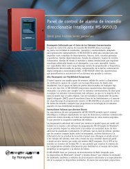
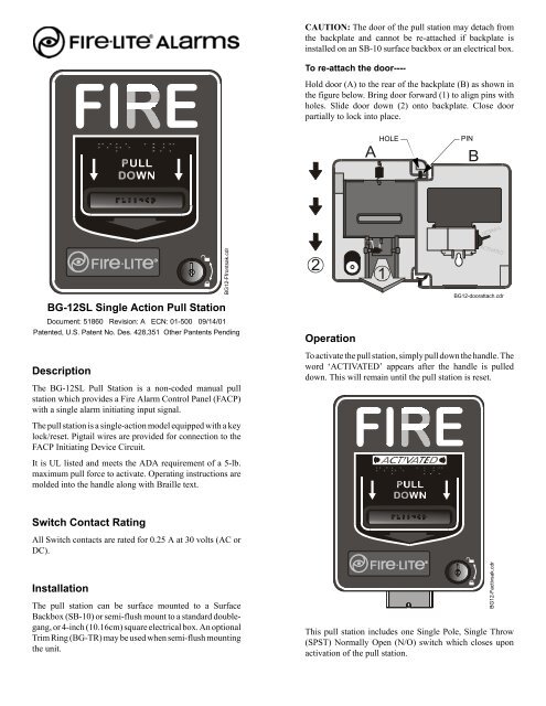
The <strong>BG</strong>-<strong>12SL</strong> <strong>Pull</strong> <strong>Station</strong> is a non-coded manual pull<br />
station which provides a <strong>Fire</strong> Alarm Control Panel (FACP)<br />
with a single alarm initiating input signal.<br />
The pull station is a single-action model equipped with a key<br />
lock/reset. Pigtail wires are provided for connection to the<br />
FACP Initiating Device Circuit.<br />
It is UL listed and meets the ADA requirement of a 5-lb.<br />
maximum pull force to activate. Operating instructions are<br />
molded into the handle along with Braille text.<br />
Switch Contact Rating<br />
All Switch contacts are rated for 0.25 A at 30 volts (AC or<br />
DC).<br />
Installation<br />
The pull station can be surface mounted to a Surface<br />
Backbox (SB-10) or semi-flush mount to a standard doublegang,<br />
or 4-inch (10.16cm) square electrical box. An optional<br />
Trim Ring (<strong>BG</strong>-TR) may be used when semi-flush mounting<br />
the unit.<br />
<strong>BG</strong>12-Ffrontsak.cdr<br />
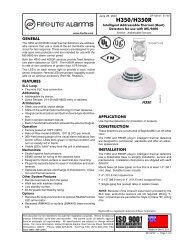
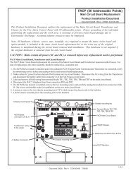
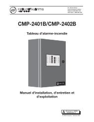
CAUTION: The door of the pull station may detach from<br />
the backplate and cannot be re-attached if backplate is<br />
installed on an SB-10 surface backbox or an electrical box.<br />
To re-attach the door----<br />
Hold door (A) to the rear of the backplate (B) as shown in<br />
the figure below. Bring door forward (1) to align pins with<br />
holes. Slide door down (2) onto backplate. Close door<br />
partially to lock into place.<br />
2<br />
Operation<br />
HOLE<br />
A B<br />
1<br />
PIN<br />
<strong>BG</strong>12-doorattach.cdr<br />
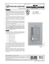
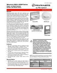
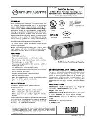
To activate the pull station, simply pull down the handle. The<br />
word ‘ACTIVATED’ appears after the handle is pulled<br />
down. This will remain until the pull station is reset.<br />
This pull station includes one <strong>Single</strong> Pole, <strong>Single</strong> Throw<br />
(SPST) Normally Open (N/O) switch which closes upon<br />
activation of the pull station.<br />
<strong>BG</strong>12-Factivsak.cdr
Resetting the <strong>Pull</strong> <strong>Station</strong><br />
1. Insert the key into the lock and rotate 1/4 turn counterclockwise.<br />
2. Open the door until the handle returns to normal.<br />
3. Close and lock the door.<br />
Note: Closing the door automatically resets the switch to the ‘Normal’<br />
position. Opening the door will not activate or deactivate the<br />
alarm switch.<br />
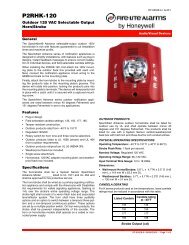
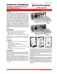
Wiring Instructions for <strong>BG</strong>-<strong>12SL</strong><br />
Prior to wiring the pull station, pull all necessary wiring<br />
through a mounted backbox and the optional trim ring.<br />
Connect the field wiring from the FACP’s IDC, or previous<br />
device on the IDC, to the pull station’s pigtail wires.<br />
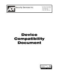
1. Connect the positive (+) FACP’s IDC wire to a red<br />
pigtail wire and the negative (–) FACP’s IDC wire to<br />
a black pigtail wire.<br />
2. Connect the positive (+) wire going to the next<br />
device, or an ELR, to the remaining red pigtail wire<br />
and the negative (–) wire going to the next device, or<br />
an ELR, to the remaining black pigtail wire.<br />
3. Maintain consistent polarity with all connections<br />
throughout the IDC.<br />
RED<br />
Positive<br />
BLACK<br />
Negative<br />
<strong>BG</strong>12-wiring3.cdr<br />
Caution<br />
Install the pull station in accordance with the supplied<br />
instructions, applicable NFPA standards, national and local<br />
<strong>Fire</strong> and Electrical codes and the requirements of the<br />
Authority Having Jurisdiction (AHJ). Conduct regular<br />
testing of the devices using appropriate NFPA standards.<br />
<strong>Fire</strong>•lite <strong>Alarms</strong> is not responsible for devices that have not<br />
been properly installed, tested and maintained.<br />
ADA Compliance<br />
For ADA compliance, if the clear floor space only allows<br />
forward approach to an object, the maximum forward reach<br />
height allowed is 48-inches (121.92cm). If the clear floor<br />
space allows parallel approach by a person in a wheelchair,<br />
the maximum side reach allowed is 54-inches (137.16cm).<br />
Document: 51860 Revision: A ECN: 01-500 09/14/01