Filters Made by MFC

Create successful ePaper yourself
Turn your PDF publications into a flip-book with our unique Google optimized e-Paper software.
PRODUCT REPORT<br />
High-Frequency <strong>Filters</strong><br />
<strong>Filters</strong><br />
<strong>Made</strong> <strong>by</strong> <strong>MFC</strong><br />
• HF filters for all kinds of applications<br />
• hugely successful in the C band filter segment<br />
• highly specialised filters to prevent WiMAX interference, among<br />
others<br />
• high-pass filters and low-pass filters can be combined to replace<br />
frequency-separating filters<br />
170 TELE-audiovision International — The World‘s Largest Digital TV Trade Magazine — 11-12/2013 — www.TELE-audiovision.com<br />
www.TELE-audiovision.com — 11-12/2013 — TELE-audiovision International — 全 球 发 行 量 最 大 的 数 字 电 视 杂 志 171
PRODUCT REPORT<br />
High-Frequency <strong>Filters</strong><br />
The Benefits of HF <strong>Filters</strong><br />
If you’re an average end<br />
user planning to set up<br />
your own Ku band satellite<br />
reception system you<br />
simply get your antenna,<br />
LNB, receiver and coax<br />
cable to connect LNB and<br />
receiver – no need to worry<br />
about anything else. If,<br />
however, you’re the kind<br />
of satellite enthusiast<br />
who always wants to dig<br />
a little deeper, or if you<br />
run a professional cable<br />
head-end or even a satellite<br />
uplink station, then<br />
you might need some<br />
more equipment, such<br />
as high-frequency filters.<br />
The market for those accessories<br />
is rather small,<br />
and this is why only a<br />
handful of manufacturers<br />
can actually supply such<br />
filters.<br />
<strong>MFC</strong> (Microwave Filter<br />
Co., Inc.) is one of them – a<br />
4<br />
company that specialises in<br />
filters and optional equipment<br />
for the high-frequency<br />
range between 5 Hz and 50<br />
GHz. <strong>MFC</strong>’s product portfolio<br />
includes waveguides,<br />
dielectric resonators, frequency-separating<br />
filters,<br />
standard filters, load resistors<br />
(frequently called ‘dummy<br />
loads’), adapters and all<br />
accessories that come with<br />
those items.<br />
Demand is particularly<br />
high for C band filters, because<br />
this is where interference<br />
frequently occurs and<br />
– more importantly – the<br />
right filter can work wonders<br />
in eliminating such interference.<br />
High-frequency filters are<br />
mostly used for eliminating<br />
unwanted signals. More often<br />
than not, such interfering<br />
signals cannot only be<br />
noticed on a single frequency,<br />
but also have a nega-<br />
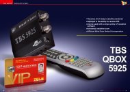
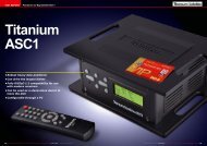
1. A sample spectrum: the signal level is high over a great<br />
frequency range, no filter is used.<br />
2. Using a high pass filter: only frequencies above the cutoff<br />
frequency pass the filter, low frequencies are attenuated<br />
substantially.<br />
3. Using a low pass filter: only frequencies under the cut-off<br />
frequency pass the filter, high frequencies are attenuated<br />
substantially.<br />
4. Band-Pass filter: combining both a high pass filter with a<br />
lower cut-off frequency and a low pass filter with a higher cut-off<br />
frequency. The result is that the centre band will pass the filter with<br />
minimal attenuation.<br />
5. Band-Rejection filter: in this case a low pass filter with a low<br />
cut-off frequency is combined with a high pass filter with a high<br />
cut-off frequency are combined. The result is that the centre band<br />
is attenuated substantially.<br />
1<br />
2<br />
3<br />
5<br />
172 TELE-audiovision International — The World‘s Largest Digital TV Trade Magazine — 11-12/2013 — www.TELE-audiovision.com
■<br />
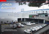
Example with a UHF filter of a pay TV operator: The left picture shows the whole CATV<br />
spectrum without any filter. The right picture shows the result of using a low pass filter<br />
with a cut-off frequency of 296 MHz.<br />
■<br />
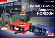
The new catalogue <strong>by</strong> <strong>MFC</strong> gives an extensive overview of all available filters made <strong>by</strong> <strong>MFC</strong>. The<br />
catalogue can also be downloaded directly from their website: www.microwavefilter.com<br />
tive impact on neighbouring<br />
frequencies. In addition, receivers<br />
and other active elements<br />
within the system are<br />
at risk of malfunctioning due<br />
to interference.<br />
The trick now is to filter<br />
out those unused frequency<br />
ranges that carry the interfering<br />
signals.<br />
Existing signals can be filtered<br />
in a number of different<br />
ways. For one, it is possible<br />
to filter out signals above<br />
and/or below a certain specified<br />
frequency. Low-pass and<br />
high-pass filters are used to<br />
that end. A low-pass filter<br />
allows all frequencies below<br />
the cut-off frequency, while a<br />
high-pass filter lets through<br />
all frequencies above a set<br />
cut-off frequency. Unwanted<br />
frequencies that are outside<br />
the cut-off frequencies are<br />
highly attenuated, whereas<br />
the target frequency range<br />
comes through with minimal<br />
attenuation.<br />
Now if you combine a highpass<br />
filter with low cut-off<br />
frequency and a low-pass<br />
filter with high cut-off frequency<br />
it is even possible to<br />
only allow a single frequency<br />
range through the filter setup.<br />
The correct term for such<br />
a configuration is band-pass<br />
filter.<br />
If, on the other hand, a<br />
low-pass filter is used in conjunction<br />
with a high-pass filter<br />
that has a higher cut-off<br />
frequency, only the centre<br />
frequency space is filtered<br />
and what we get is a socalled<br />
reject filter.<br />
Then again, what’s the use<br />
of all those filters? To start<br />
with, they allow providing<br />
individual frequency bands<br />
to different receivers without<br />
those receivers having to<br />
share frequency bands. SCR<br />
(Single Cable Routing) distribution<br />
setups, for instance,<br />
make use of this approach,<br />
with up to eight receivers<br />
having independent access<br />
to all satellite channels via a<br />
single cable that is led from<br />
one wall outlet to the next.<br />
In such a configuration, each<br />
receiver is assigned a dedicated<br />
frequency band with<br />
a central router modulating<br />
the required transponder<br />
onto the corresponding frequency<br />
band.<br />
Network operators, on<br />
the other hand, use filters<br />
in analog CATV networks<br />
as well to make sure customers<br />
with less expensive<br />
subscriptions cannot receive<br />
premium channels. Those<br />
channels are usually transmitted<br />
on higher frequencies<br />
and a sealed low-pass filter<br />
at the transfer point just outside<br />
the house or apartment<br />
prevents those subscribers<br />
from watching channels they<br />
don’t pay for.<br />
The most important reason<br />
for installing filters,<br />
however, can be found in the<br />
fact that neighbouring signals<br />
are generally prone to<br />
interference from each other.<br />
Unlike the number of different<br />
applications and uses<br />
sharing the same resources,<br />
the frequency range cannot<br />
be increased at random<br />
and has to be accepted as<br />
a given, with all its capacity<br />
constraints. Even very strict<br />
technical regulations and<br />
mandatory frequency charts<br />
cannot do much in terms of<br />
interference prevention.<br />
A prominent everyday example<br />
is interference in the<br />
DVB-T/T2 and ATSC range<br />
caused <strong>by</strong> LTE signals. As<br />
far as the regulator is concerned,<br />
all applications<br />
should work side <strong>by</strong> side<br />
in the frequency spectrum<br />
without doing harm to each<br />
other <strong>by</strong> using only those<br />
frequencies that have been<br />
specifically sat aside for each<br />
application.<br />
We all know too well, however,<br />
that in the real world<br />
it’s often an entirely different<br />
story.<br />
Generally speaking, highfrequency<br />
interference can<br />
<strong>by</strong> caused <strong>by</strong> a number of<br />
different phenomena.<br />
As far as receivers are<br />
concerned:<br />
• Interference from neighbouring<br />
frequencies<br />
• Interference in the IF<br />
(intermediate frequency)<br />
• Interference in the LO<br />
(local oscillator) frequency<br />
Interference can also be<br />
caused at the transmitting<br />
end:<br />
• In addition to the desired<br />
emission frequency,<br />
neighbouring frequencies<br />
may be affected <strong>by</strong> unwanted<br />
emissions that are<br />
caused <strong>by</strong> the modulator.<br />
• Harmonics emissions<br />
• Interference caused <strong>by</strong><br />
intermodulation<br />
When it comes to selecting<br />
an appropriate filter it<br />
is paramount to understand<br />
all parameters given <strong>by</strong> the<br />
manufacturer. Listed below<br />
are the most important of<br />
them:<br />
• Attenuation<br />
Attenuation is measured<br />
in decibels and indicates<br />
the level <strong>by</strong> which the input<br />
signal is decreased. To find<br />
out the exact attenuation<br />
the signal level is measured<br />
first at input and then again<br />
at output, with the resulting<br />
difference in decibels (dB)<br />
being the achieved attenuation.<br />
• Bandwidth<br />
This parameter indicates<br />
the bandwidth of a bandpass<br />
filter, that is to say the<br />
frequency range that passes<br />
through the filter with a relative<br />
insertion loss of 3 dB or<br />
less.<br />
• Cut-off frequency<br />
This is the frequency that<br />
triggers either the high-pass<br />
New High-Frequency <strong>Filters</strong> <strong>by</strong> <strong>MFC</strong><br />
for the C-Band<br />
Model 18253 - C-Band (INSAT) Transmit Reject Filter<br />
• This TRF provides deep rejection of the transmit band with minimal effect on the<br />
receive band.<br />
• Ideal for INSAT and other Region-Specific Receive Applications<br />
• Alternate Flange Configurations are Available Upon Request<br />
Pass band<br />
4.5 - 4.8 GHz (C-INSAT Downlink)<br />
Insertion Loss<br />
0.50 dB Max<br />
VSWR<br />
1.30:1 Max<br />
Reject Band<br />
6.725 - 7.025 GHz (C-INSAT Uplink)<br />
Rejection<br />
80 dB Min<br />
Operating Temperature Range -10°C to +60°C<br />
Flanges<br />
CPR229G<br />
Dimensions<br />
3.95” x 3.88” x 2.75” (100mm x 98mm x 70mm)<br />
Finish<br />
Gloss White Lacquer<br />
Model 18323 - C-Band (INSAT) Receive Reject Filter<br />
• Same as before but rejection of the receive (Downlink) band<br />
Passband<br />
6.725 - 7.025 GHz<br />
Insertion Loss<br />
0.10 dB Approx.<br />
VSWR<br />
1.22:1 Max<br />
Reject Band<br />
4.5 - 4.8 GHz<br />
Rejection<br />
80 dB Typ<br />
Flanges<br />
CPR137/CPR137G<br />
Dimensions<br />
5.00“ x 2.69“ x 1.94“ (127mm x 68mm x 49mm)<br />
Finish<br />
White Lacquer<br />
Model 18506 - Multi-Purpose C-Band Transmit Filter<br />
• This Uplink filter not only rejects the entire receive band (below 4.2 GHz), but<br />
it also rejects transmissions from other potential sources of interference etc., that<br />
RRFs do not.<br />
• Ideal for use in high-density transmit paths, like:<br />
Wireless Services (Point-Multipoint) 4.55 - 4.9 GHz<br />
Maritime & Aeronautical Radio Navigation 4.2 - 5.6 GHz<br />
Broadcast Auxiliary Services<br />
6.95 -7.15 GHz<br />
• Ideal for all “standard band” C-Band Uplink Applications<br />
• Easy bolt-on installation and no power supply required<br />
Passband<br />
5.925 - 6.425 GHz<br />
Passband Loss<br />
0.3 dB Max<br />
Passband Return Loss<br />
17.7 dB Min<br />
Rejection<br />
50 dB Min @ 5.625 GHz<br />
40 dB Min @ 6.725 GHz<br />
Power Rating<br />
400 Watts<br />
Flanges<br />
CPR137F<br />
Dimensions<br />
9.50” x 2.69” x 1.94” (241mm x 68mm x 49mm)<br />
Finish<br />
Gloss White Lacquer<br />
174 TELE-audiovision International — The World‘s Largest Digital TV Trade Magazine — 11-12/2013 — www.TELE-audiovision.com<br />
www.TELE-audiovision.com — 11-12/2013 — TELE-audiovision International — 全 球 发 行 量 最 大 的 数 字 电 视 杂 志 175
filter or low-pass filter.<br />
• Decibel<br />
This measuring unit gives<br />
the relation between two<br />
signals (P1 and P2) based on<br />
the following equation:<br />
dB = 10 Log10 (P1/P2)<br />
• Insertion loss<br />
Like any other active or<br />
passive element between the<br />
antenna and the receiver/<br />
transmitter the use of a filter<br />
causes a certain amount<br />
of overall signal attenuation.<br />
The insertion loss parameter<br />
indicates that attenuation,<br />
which should be as low as<br />
possible (max. 3 dB).<br />
• Phase shift<br />
This parameter indicates<br />
the runtime shift of the signal<br />
that is caused <strong>by</strong> the filter.<br />
In general, phase shifts<br />
become more pronounced<br />
with higher frequencies,<br />
which means digital signals<br />
are more affected than<br />
analog signals.<br />
Problems<br />
in the C Band<br />
WiMAX and radar applications<br />
(weather radar, in particular)<br />
are major sources of<br />
interference in the C band.<br />
For uninterrupted C band<br />
reception it can therefore<br />
be recommended to use<br />
band-pass filters that only<br />
allow the required frequency<br />
range to pass through.<br />
As far as the C band is<br />
concerned, we have to draw<br />
a line between the standard<br />
C band and the extended C<br />
band. To complicate matters<br />
even further, some regions,<br />
such as Russia for example,<br />
use a slightly different frequency<br />
range for the C band.<br />
This means that the actual<br />
frequency band defines the<br />
filter to be used. In recent<br />
years, WiMAX (Worldwide<br />
Interoperatibility for Microwave<br />
Access) has become a<br />
source of much frustration.<br />
WiMAX is used for wireless<br />
Internet access in the 2300<br />
MHz, 2500 MHz and 3500<br />
MHz bands and as such has<br />
enormous potential for causing<br />
interference in the C<br />
band.<br />
The standard approach in<br />
such a case calls for adding<br />
a highly selective bandpass<br />
filter, whose frequency<br />
range corresponds to the<br />
local footprint (that is 3700-<br />
4200 MHz, 3400-4200 MHz,<br />
etc.). More recently, however,<br />
WiMAX was also launched<br />
in many regions worldwide<br />
in the 3400-3800 MHz frequency<br />
band. The resulting<br />
in-band interference in the C<br />
band can no longer be eliminated<br />
with the help of conventional<br />
band-pass filters,<br />
since signals from WiMAX<br />
transmitters using 3700 MHz<br />
and consequently impacting<br />
the 3700-4200 MHz range,<br />
will still come through with<br />
a standard band-pass filter<br />
that allows all frequencies<br />
between 3700 and 4200 MHz<br />
to pass through. This means<br />
the interfering WiMAX signal<br />
is not blocked and such<br />
a filter does not solve the<br />
problem. A special filter is<br />
required in such a scenario<br />
– one that only lets through<br />
signals on frequencies of<br />
3750 MHz and above, for example.<br />
<strong>Filters</strong> for such high-frequency<br />
applications are extremely<br />
complex and a lot<br />
of expertise and experience<br />
are necessary for designing<br />
state-of-the-art filters.<br />
What’s more, special manufacturing<br />
processes must be<br />
adhered to, since we’re not<br />
only talking about the odd<br />
electronic switch or circuit<br />
C-Band TX(MHz) RX (MHz)<br />
Standard 5850–6425 3625–4200<br />
Extended 6425–6725 3400–3625<br />
New High-Frequency <strong>Filters</strong> <strong>by</strong> <strong>MFC</strong><br />
for the C-Band<br />
Model 13961W-I - International (Extended)<br />
C-Band Interference Elimination Filter<br />
• No other filter in the industry provides as much rejection of undesired signals in<br />
such a compact size.<br />
• Eliminates WiMAX, RADAR and virtually all other sources of out-of-band interference<br />
• Lightweight - Aluminium Construction<br />
• Ready to install between LNB & feed horn<br />
Pass band<br />
3.6 - 4.2 GHz<br />
Pass band Loss<br />
0.5 dB Typ @ centre band<br />
0.5 dB Typ roll-off @ band edges<br />
Pass band VSWR<br />
1.5:1 Typ<br />
Group Delay Variation<br />
8 ns Max<br />
Rejection<br />
45 dB Typ @ 3.55 GHz / 4.25 GHz<br />
55 dB Typ @ 3.45 GHz / 4.35 GHz<br />
70 dB Typ @ 3.40 GHz / 4.40 GHz<br />
Flanges<br />
CPR229G (Input), CPR229F (Output)<br />
Length<br />
5.49“ (13.9 cm)<br />
Weight<br />
1.125 lbs. (0.51 Kg)<br />
Finish<br />
Gloss White Lacquer<br />
here. High-frequency signals<br />
are transmitted even without<br />
electronic conductors<br />
in place, which is why such<br />
filters mainly consist of hollow<br />
conductors in the form of<br />
waveguides.<br />
When you look at one of<br />
those filters as an absolute<br />
layperson, it’s almost impossible<br />
to tell where and how<br />
the filter can be integrated<br />
into the existing reception<br />
system. The answer is surprisingly<br />
straightforward:<br />
right at the antenna between<br />
the feed horn and the LNB/<br />
LNA.<br />
<strong>Filters</strong> of this kind are<br />
mainly produced with computer-assisted<br />
milling in<br />
combination with special<br />
CAM software which calculates<br />
the exact milling movements.<br />
As far as the C band<br />
is concerned, <strong>MFC</strong> is the<br />
leading manufacturer worldwide<br />
of filters for eliminating<br />
interference. No other company<br />
even comes close to<br />
<strong>MFC</strong> and its comprehensive<br />
portfolio of filters for radar,<br />
WiMAX or any other signal<br />
causing interference.<br />
All it takes is a look at recently<br />
introduced filters,<br />
which <strong>MFC</strong> has started to<br />
produce not too long ago<br />
to see what this company is<br />
made of. And of course TELEaudiovision<br />
readers can take<br />
a first-row seat when some<br />
of <strong>MFC</strong>’s major new developments<br />
take centre stage<br />
below.<br />
For filters in the C band<br />
there’s no way around <strong>MFC</strong>,<br />
a company specialising in the<br />
development and production<br />
of those special purpose filters,<br />
and which therefore is<br />
in a position to offer products<br />
with top-notch specifications.<br />
176 TELE-audiovision International — The World‘s Largest Digital TV Trade Magazine — 11-12/2013 — www.TELE-audiovision.com