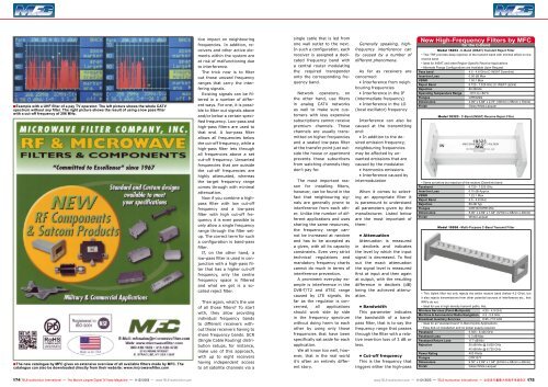
Filtros Hechos por MFC

Create successful ePaper yourself
Turn your PDF publications into a flip-book with our unique Google optimized e-Paper software.
■<br />
Example with a UHF filter of a pay TV operator: The left picture shows the whole CATV<br />
spectrum without any filter. The right picture shows the result of using a low pass filter<br />
with a cut-off frequency of 296 MHz.<br />
■<br />
The new catalogue by <strong>MFC</strong> gives an extensive overview of all available filters made by <strong>MFC</strong>. The<br />
catalogue can also be downloaded directly from their website: www.microwavefilter.com<br />
tive impact on neighbouring<br />
frequencies. In addition, receivers<br />
and other active elements<br />
within the system are<br />
at risk of malfunctioning due<br />
to interference.<br />
The trick now is to filter<br />
out those unused frequency<br />
ranges that carry the interfering<br />
signals.<br />
Existing signals can be filtered<br />
in a number of different<br />
ways. For one, it is possible<br />
to filter out signals above<br />
and/or below a certain specified<br />
frequency. Low-pass and<br />
high-pass filters are used to<br />
that end. A low-pass filter<br />
allows all frequencies below<br />
the cut-off frequency, while a<br />
high-pass filter lets through<br />
all frequencies above a set<br />
cut-off frequency. Unwanted<br />
frequencies that are outside<br />
the cut-off frequencies are<br />
highly attenuated, whereas<br />
the target frequency range<br />
comes through with minimal<br />
attenuation.<br />
Now if you combine a highpass<br />
filter with low cut-off<br />
frequency and a low-pass<br />
filter with high cut-off frequency<br />
it is even possible to<br />
only allow a single frequency<br />
range through the filter setup.<br />
The correct term for such<br />
a configuration is band-pass<br />
filter.<br />
If, on the other hand, a<br />
low-pass filter is used in conjunction<br />
with a high-pass filter<br />
that has a higher cut-off<br />
frequency, only the centre<br />
frequency space is filtered<br />
and what we get is a socalled<br />
reject filter.<br />
Then again, what’s the use<br />
of all those filters? To start<br />
with, they allow providing<br />
individual frequency bands<br />
to different receivers without<br />
those receivers having to<br />
share frequency bands. SCR<br />
(Single Cable Routing) distribution<br />
setups, for instance,<br />
make use of this approach,<br />
with up to eight receivers<br />
having independent access<br />
to all satellite channels via a<br />
single cable that is led from<br />
one wall outlet to the next.<br />
In such a configuration, each<br />
receiver is assigned a dedicated<br />
frequency band with<br />
a central router modulating<br />
the required transponder<br />
onto the corresponding frequency<br />
band.<br />
Network operators, on<br />
the other hand, use filters<br />
in analog CATV networks<br />
as well to make sure customers<br />
with less expensive<br />
subscriptions cannot receive<br />
premium channels. Those<br />
channels are usually transmitted<br />
on higher frequencies<br />
and a sealed low-pass filter<br />
at the transfer point just outside<br />
the house or apartment<br />
prevents those subscribers<br />
from watching channels they<br />
don’t pay for.<br />
The most im<strong>por</strong>tant reason<br />
for installing filters,<br />
however, can be found in the<br />
fact that neighbouring signals<br />
are generally prone to<br />
interference from each other.<br />
Unlike the number of different<br />
applications and uses<br />
sharing the same resources,<br />
the frequency range cannot<br />
be increased at random<br />
and has to be accepted as<br />
a given, with all its capacity<br />
constraints. Even very strict<br />
technical regulations and<br />
mandatory frequency charts<br />
cannot do much in terms of<br />
interference prevention.<br />
A prominent everyday example<br />
is interference in the<br />
DVB-T/T2 and ATSC range<br />
caused by LTE signals. As<br />
far as the regulator is concerned,<br />
all applications<br />
should work side by side<br />
in the frequency spectrum<br />
without doing harm to each<br />
other by using only those<br />
frequencies that have been<br />
specifically sat aside for each<br />
application.<br />
We all know too well, however,<br />
that in the real world<br />
it’s often an entirely different<br />
story.<br />
Generally speaking, highfrequency<br />
interference can<br />
by caused by a number of<br />
different phenomena.<br />
As far as receivers are<br />
concerned:<br />
• Interference from neighbouring<br />
frequencies<br />
• Interference in the IF<br />
(intermediate frequency)<br />
• Interference in the LO<br />
(local oscillator) frequency<br />
Interference can also be<br />
caused at the transmitting<br />
end:<br />
• In addition to the desired<br />
emission frequency,<br />
neighbouring frequencies<br />
may be affected by unwanted<br />
emissions that are<br />
caused by the modulator.<br />
• Harmonics emissions<br />
• Interference caused by<br />
intermodulation<br />
When it comes to selecting<br />
an appropriate filter it<br />
is paramount to understand<br />
all parameters given by the<br />
manufacturer. Listed below<br />
are the most im<strong>por</strong>tant of<br />
them:<br />
• Attenuation<br />
Attenuation is measured<br />
in decibels and indicates<br />
the level by which the input<br />
signal is decreased. To find<br />
out the exact attenuation<br />
the signal level is measured<br />
first at input and then again<br />
at output, with the resulting<br />
difference in decibels (dB)<br />
being the achieved attenuation.<br />
• Bandwidth<br />
This parameter indicates<br />
the bandwidth of a bandpass<br />
filter, that is to say the<br />
frequency range that passes<br />
through the filter with a relative<br />
insertion loss of 3 dB or<br />
less.<br />
• Cut-off frequency<br />
This is the frequency that<br />
triggers either the high-pass<br />
New High-Frequency Filters by <strong>MFC</strong><br />
for the C-Band<br />
Model 18253 - C-Band (INSAT) Transmit Reject Filter<br />
• This TRF provides deep rejection of the transmit band with minimal effect on the<br />
receive band.<br />
• Ideal for INSAT and other Region-Specific Receive Applications<br />
• Alternate Flange Configurations are Available Upon Request<br />
Pass band<br />
4.5 - 4.8 GHz (C-INSAT Downlink)<br />
Insertion Loss<br />
0.50 dB Max<br />
VSWR<br />
1.30:1 Max<br />
Reject Band<br />
6.725 - 7.025 GHz (C-INSAT Uplink)<br />
Rejection<br />
80 dB Min<br />
Operating Temperature Range -10°C to +60°C<br />
Flanges<br />
CPR229G<br />
Dimensions<br />
3.95” x 3.88” x 2.75” (100mm x 98mm x 70mm)<br />
Finish<br />
Gloss White Lacquer<br />
Model 18323 - C-Band (INSAT) Receive Reject Filter<br />
• Same as before but rejection of the receive (Downlink) band<br />
Passband<br />
6.725 - 7.025 GHz<br />
Insertion Loss<br />
0.10 dB Approx.<br />
VSWR<br />
1.22:1 Max<br />
Reject Band<br />
4.5 - 4.8 GHz<br />
Rejection<br />
80 dB Typ<br />
Flanges<br />
CPR137/CPR137G<br />
Dimensions<br />
5.00“ x 2.69“ x 1.94“ (127mm x 68mm x 49mm)<br />
Finish<br />
White Lacquer<br />
Model 18506 - Multi-Purpose C-Band Transmit Filter<br />
• This Uplink filter not only rejects the entire receive band (below 4.2 GHz), but<br />
it also rejects transmissions from other potential sources of interference etc., that<br />
RRFs do not.<br />
• Ideal for use in high-density transmit paths, like:<br />
Wireless Services (Point-Multipoint) 4.55 - 4.9 GHz<br />
Maritime & Aeronautical Radio Navigation 4.2 - 5.6 GHz<br />
Broadcast Auxiliary Services<br />
6.95 -7.15 GHz<br />
• Ideal for all “standard band” C-Band Uplink Applications<br />
• Easy bolt-on installation and no power supply required<br />
Passband<br />
5.925 - 6.425 GHz<br />
Passband Loss<br />
0.3 dB Max<br />
Passband Return Loss<br />
17.7 dB Min<br />
Rejection<br />
50 dB Min @ 5.625 GHz<br />
40 dB Min @ 6.725 GHz<br />
Power Rating<br />
400 Watts<br />
Flanges<br />
CPR137F<br />
Dimensions<br />
9.50” x 2.69” x 1.94” (241mm x 68mm x 49mm)<br />
Finish<br />
Gloss White Lacquer<br />
174 TELE-audiovision International — The World‘s Largest Digital TV Trade Magazine — 11-12/2013 — www.TELE-audiovision.com<br />
www.TELE-audiovision.com — 11-12/2013 — TELE-audiovision International — 全 球 发 行 量 最 大 的 数 字 电 视 杂 志 175