VSG compressor - Emerson Climate Technologies
VSG compressor - Emerson Climate Technologies
VSG compressor - Emerson Climate Technologies

Create successful ePaper yourself
Turn your PDF publications into a flip-book with our unique Google optimized e-Paper software.
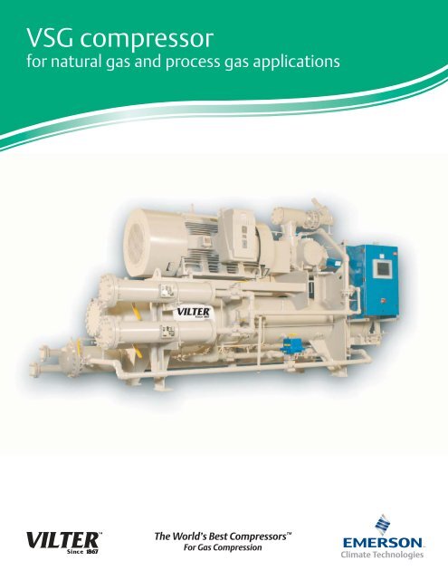
<strong>VSG</strong> <strong>compressor</strong><br />
for natural gas and process gas applications<br />
The World’s Best Compressors <br />
For Gas Compression
Why choose a Vilter single screw <strong>compressor</strong>?<br />
Vilter’s <strong>VSG</strong> single screw gas <strong>compressor</strong>s deliver longer life, higher reliability and better energy<br />
efficiency than twin screw <strong>compressor</strong>s and have fewer moving parts than reciprocating <strong>compressor</strong>s.<br />
The key to the single screw <strong>compressor</strong>’s reliability is in its balanced design. At the core of the positive<br />
displacement rotary <strong>compressor</strong> is a single main rotor intermeshed with two opposing gaterotors. The<br />
balanced design results in ultra-low bearing loads with significantly decreased vibration and sound levels.<br />
The key to the single screw <strong>compressor</strong>’s high energy efficiency is Vilter’s exclusive Parallex slide system<br />
allowing the <strong>compressor</strong> to run at optimum efficiency through its full range of capacity.<br />
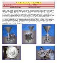
Part Load Energy Consumption –<br />
Single Screw vs. Twin Screw<br />
Isentropic Efficiency Comparison<br />
Between Variable and Fixed Volume
Parallex slide system<br />
It’s the key to part load efficiencies far superior to twin screw<br />
<strong>compressor</strong>s. Capacity and volume slides move independently of<br />
each other based on load, eliminating over or under compression<br />
and saving motor horsepower.<br />
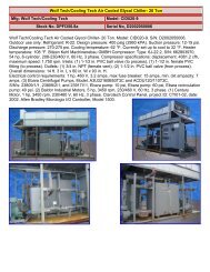
Allen-Bradley programmable controller<br />
The CompactLogix programmable controller with an A-B PanelView<br />
1000 graphic display provides high performance in a small footprint<br />
for stand alone operation or for integrated system control.<br />
Large capacity oil filter<br />
Filters will remove all particles, 25 microns or larger, from the oil before<br />
the <strong>compressor</strong>. Filter assemblies are equipped with transducers to<br />
measure pressure drop and shut-off valves for isolation and servicing.<br />
Oil cooling options<br />
• Water cooled<br />
• Air cooled<br />
Applications<br />
Features and benefits<br />
• Gas liquification<br />
• Vapor recovery<br />
• Flare gas recovery<br />
• Coal bed methane recovery<br />
• Field and fuel gas boosting<br />
• Wellhead recovery<br />
• Enhanced oil recovery<br />
• Landfill gas recovery<br />
• LNG boil off<br />
• Gas gathering<br />
• BIO - gas<br />
• Digester<br />
• CO 2<br />
• Nitrogen<br />
• Hydrogen<br />
• Refrigerant<br />
•Displacements from 310 to 2,048 CFM<br />
• Variable capacity control 10-100%<br />
• Variable volume ratios 1.2 – 7.0<br />
• Compression ratios 2 – 20<br />
• Electronic actuators are weatherproof and conform to<br />
Class 1, Group C&D, Division 2 Classification<br />
• Balanced main rotor with no axial or radial loads<br />
• Parallex slide system for maximum operating efficiency<br />
• Low bearing loads – no hydrodynamic bearings<br />
• High suction pressure capability is standard<br />
• Clockwise rotation models available<br />
• Low noise levels<br />
• Low maintenance costs
Unit features<br />
Standard construction<br />
• Main bearings – Roller and ball type angular contact<br />
thrust.<br />
• Gaterotor bearings – Roller and ball type angular contact<br />
thrust.<br />
• Hand wheels or optical slide valve motor for capacity and<br />
volume control. Suitable for Class 1, Group C+D, Div. II.<br />
• Variable vi - Independent volume control and capacity<br />
control for improving efficiencies.<br />
• Separate prelube oil pump with TEFC drive motor.<br />
• Lube oil piping is carbon steel, using socket weld or butt<br />
weld connections. Threaded connections are kept to a<br />
minimum.<br />
• ASME designed oil separator with coalesing oil filter.<br />
• CompactLogix programmable controller with an A-B<br />
PanelView 1000 graphic display<br />
• Separate stop and check valves for both suction and<br />
discharge lines.<br />
Process gas circuit<br />
• Suction gas stop and check valve.<br />
• Suction line strainer – The strainer is stainless steel mesh<br />
construction and suited to process gas applications.<br />
• Process gas/oil separator – The separator is capable of<br />
removing the oil from the discharge gas stream and is an<br />
ASME-coded vessel which uses five stages of separation to<br />
achieve an oil loss of below 4 ppm.<br />
• Discharge oil separator relief valve.<br />
Injection oil circuit<br />
• Oil prelube pump with TEFC motor.<br />
• Oil cooler/temperature control valve – An oil cooler,<br />
either air or water cooled, must be used to remove the<br />
heat of compression from the oil stream. A two way<br />
temperature control valve is used to maintain precise oil<br />
injection temperature to the <strong>compressor</strong> VIA PID loop<br />
control in PLC<br />
• Oil filtration – Filtration down to 25 microns nominal.<br />
Optional dual filters are recommended to allow replacement<br />
of one cartridge while the <strong>compressor</strong> continues<br />
running with the other cartridge in service<br />
• Oil heater –Oil heaters are supplied to maintain oil temperature<br />
of at least 90°F when the <strong>compressor</strong> is<br />
not running<br />
Available options<br />
• Stainless steel lube oil circuit<br />
• Suction bypass connection for fuel gas booster application<br />
• Dual oil pumps<br />
• Dual oil filters<br />
• Water cooled or air cooled oil coolers<br />
• High and low ambient temperature options<br />
Note – Because the oil system on the <strong>VSG</strong> <strong>compressor</strong> utilizes discharge gas<br />
pressure as the means to move the injection oil through the system, it<br />
must be remembered that all components of the oil system are exposed<br />
to full discharge pressure and must be pressure rated accordingly.<br />
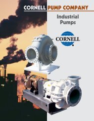
Flow Diagram (Figure 1)
Instrumentation<br />
Pressure<br />
There are four pressure transducers to read system pressures<br />
as listed below (Figure 1).<br />
PT1 suction pressure transducer<br />
(-15.0 - 400 PSIG) measures the gas suction pressure into<br />
the <strong>compressor</strong> housing.<br />
PT2 discharge pressure transducer<br />
(-15.0 - 400 PSIG) measures the discharge pressure of the<br />
process gas in the separator.<br />
PT3 oil filter inlet pressure transducer<br />
(-15.0 - 400 PSIG) measures the oil pressure as it enters the<br />
oil filter canisters.<br />
PT4 oil manifold pressure transducer<br />
(-15.0 - 400 PSIG) measures the oil pressure downstream<br />
of the oil filter as the oil is injected into the <strong>compressor</strong>.<br />
Additional pressure transducers may be required and installed by the customer<br />
for pressure readings at customer specified points such as process gas<br />
discharge pressure from the package boundary, cooling water pressure to<br />
and/or from the oil cooler, etc.<br />
Temperature<br />
There are four temperature readings for processor control, as<br />
listed below (Figure 1).<br />
RTD1 suction temperature RTD<br />
measures the temperature of the incoming suction gas.<br />
RTD2 discharge temperature RTD<br />
measures the temperature of the gas/oil mixture as it is<br />
discharged from the <strong>compressor</strong> housing.<br />
RTD3 oil separator temperature RTD<br />
measures the temperature of the oil in the separator sump.<br />
RTD4 oil Injection temperature RTD<br />
measures the temperature of the oil as it is injected into<br />
the <strong>compressor</strong>.<br />
Alarm and shutdown annunciation/indication<br />
The control system for the <strong>VSG</strong> <strong>compressor</strong> must protect<br />
the machine from running outside of normal operating<br />
conditions. This is accomplished by providing operators with<br />
alarms when operating parameters have reached an abnormal<br />
condition, and by automatically stopping the <strong>compressor</strong><br />
before these conditions can cause a unit failure.<br />
Safety setpoints:<br />
• Low gas suction temperature<br />
• High gas discharge temperature<br />
• Low oil separator start temperature<br />
• Low oil separator run temperature<br />
• Low oil injection temperature<br />
• High oil injection temperature<br />
• Low suction pressure<br />
• High discharge pressure<br />
• Prelube oil pressure<br />
• Low oil pressure<br />
• High starting oil filter differential pressure<br />
• High running oil filter differential pressure<br />
• High motor amperage limit<br />
In most cases, the safety setpoints described will have<br />
settings which are dictated by process requirements, and not<br />
necessarily mechanical constraints of the <strong>compressor</strong>.Process<br />
pressures and temperatures may vary considerably depending<br />
on the application of the <strong>compressor</strong>. The <strong>VSG</strong> <strong>compressor</strong><br />
is designed to operate in a broad range of applications.<br />
Minimum and maximum values for each safety setpoint are<br />
provided, while precise settings for the safety setpoints must<br />
be derived for each installation.<br />
Additional RTD’s may be required and installed by the customer for<br />
temperature readings at customer specified points such as discharge gas<br />
temperature from the package boundary, cooling water temperature to and/<br />
or from the oil cooler, gas aftercooler temperature, etc.<br />
Additional instrumentation<br />
• Motor current transformer<br />
• Optical actuators for capacity and volume slide indication<br />
Other options<br />
• Remote start/stop input<br />
• Remote alarm/trip output
Application guidelines<br />
To ensure the successful operation of the <strong>VSG</strong> <strong>compressor</strong>,<br />
the guidelines described below should be followed.<br />
Proper lubrication is critical to the operation of the <strong>VSG</strong><br />
<strong>compressor</strong>. The <strong>compressor</strong> relies on the injected oil to<br />
absorb and remove the heat of compression, to seal the<br />
compression chambers formed in the flutes of the screw,<br />
and to lubricate all moving parts. For this reason, it is imperative<br />
that the oil chosen be of correct viscosity, and that<br />
sufficient oil flow be provided at all times, using an auxiliary<br />
oil pump when necessary. The oil chosen must be compatible<br />
with the process gas, to prevent absorption of the gas<br />
into the oil, which would dilute the oil and reduce the viscosity.<br />
Also oil filtration to 25 micron nominal particle size<br />
is required to ensure that only clean oil is injected into the<br />
<strong>compressor</strong>. For assistance in choosing the correct oil for<br />
the application and in sizing an auxiliary oil pump, consult a<br />
Vilter representative.<br />
Injection oil temperature must be closely controlled for<br />
optimum performance. Oil temperature must be maintained<br />
a minimum of 15 - 20°F above the gas mixture dewpoint at<br />
anytime to prevent condensation or liquid knockout from<br />
occurring within the <strong>compressor</strong>.<br />
Gas composition plays a role in the performance of the <strong>VSG</strong><br />
<strong>compressor</strong> as well. While the <strong>VSG</strong> is capable of handling a<br />
wide variety of gases, if H 2<br />
S is present in the process gas in<br />
any concentration, special oil additives are required to<br />
protect the <strong>compressor</strong> from corrosion. Levels below 100<br />
PPM of H 2<br />
S allow the standard warranty to apply.<br />
Typical gases handled: Natural gas, landfill gas, carbon<br />
dioxide, propane, helium, propylene and ammonia.<br />
Other gases will need to be reviewed for compatibility<br />
and operational performance by Vilter.<br />
Compressor capacity and design limitations - standard models<br />
Description<br />
<strong>VSG</strong><br />
301<br />
<strong>VSG</strong><br />
361<br />
<strong>VSG</strong><br />
401<br />
<strong>VSG</strong><br />
501<br />
<strong>VSG</strong><br />
601<br />
<strong>VSG</strong><br />
701<br />
<strong>VSG</strong><br />
751<br />
<strong>VSG</strong><br />
901<br />
<strong>VSG</strong><br />
1051<br />
<strong>VSG</strong><br />
1201<br />
<strong>VSG</strong><br />
1551<br />
<strong>VSG</strong><br />
1851<br />
<strong>VSG</strong><br />
2101<br />
<strong>VSG</strong><br />
2401<br />
<strong>VSG</strong><br />
2601<br />
<strong>VSG</strong><br />
2801<br />
<strong>VSG</strong><br />
3001<br />
Rotor diameter (mm) 205 205 205 240 240 240 280 280 310 310 350 350 350 401 401 401 401<br />
Gaterotor diameter (mm) 195 205 216 225 240 252 268 280 298 310 331 350 368 388 400 411 416<br />
Max. HP 3600 RPM* 300 HP 500 HP 675 HP 1000 HP 2000 HP<br />
Max. allowable torque 444 ft. lbs. 739 ft. lbs. 998 ft. lbs. 1479 ft. lbs. 2958 ft. lbs.<br />
Rotor speed (RPM) 1200-4200 1200-4000 1200-3800<br />
Direction of rotation<br />
CCW facing<br />
drive end<br />
CW facing<br />
drive end<br />
CCW facing drive end<br />
Drive type<br />
Direct drive, electric motor, gas engine<br />
Built-in volume ratio<br />
1.2 to 7.0 (Continuously variable automatic, or manual control)<br />
Capacity range<br />
10% to 100% (Continuously variable automatic, or manual control)<br />
Bare comp. MAWP<br />
(psig)**<br />
515 485 535<br />
Max. pressure differential<br />
(psig)***<br />
325<br />
Min. inlet temp. (°F)<br />
-50°F<br />
Max. inlet temp. (°F) 180°F<br />
Max. disch. temp. (°F)<br />
225° (Contact Vilter for increased temperature limits)<br />
Max. oil temp. (°F)<br />
190° (Contact Vilter for increased temperature limits)<br />
*Higher limits are available. Consult Vilter Manuafacturing LLC.<br />
**Higher discharge pressures are achievable. Consult Vilter Manuafacturing LLC. for approval.<br />
***Higher differential pressures can be achieved. Consult Vilter Manuafacturing LLC. for approval.<br />
Note: MAWP (Maximum Allowable Working Pressure). The relief valve setting must be below the MAWP. The relief valve is usually set 10% lower than the MAWP.
ROTATION<br />
<strong>VSG</strong> unit dimensions and specifications<br />
Models <strong>VSG</strong> 301-701<br />
C<br />
Models <strong>VSG</strong> 751-3001<br />
A<br />
B<br />
D<br />
Models <strong>VSG</strong> 301-701, left, are<br />
shown with a standard C-Flange<br />
motor mount, single oil filter<br />
and standard water-cooled oil<br />
cooler which is noted by the D<br />
dimension on the drawing.<br />
Models <strong>VSG</strong> 751-3001 drawings<br />
illustrate the optional dual oil<br />
filter and the optional remote<br />
mounted oil cooler which can<br />
be air cooled.<br />
C<br />
It is important to note that all<br />
<strong>VSG</strong> models can be fitted with<br />
single or dual oil filters, watercooled<br />
oil cooler or remote<br />
mounted oil cooler.<br />
<strong>VSG</strong> unit dimensions<br />
Vilter model<br />
A<br />
Standard connection size*<br />
Suction<br />
Discharge<br />
A<br />
Length<br />
B<br />
D<br />
Unit dimensions (approx.)*<br />
B<br />
Width<br />
C<br />
Height<br />
D<br />
Optional oil cooler<br />
Approx. shipping<br />
weight (lbs)**<br />
<strong>VSG</strong>-301 3” 3” 8’-10” 4’-2” 6’ 7-3/4” 7000<br />
<strong>VSG</strong>-361 3” 3” 8’-10” 4’-2” 6’ 7-3/4” 7300<br />
<strong>VSG</strong>-401 3” 3” 8’-10” 4’-2” 6’ 7-3/4” 7500<br />
<strong>VSG</strong>-501 4” 3” 8’-9” 3’-8” 7’-6” 10-3/4” 8500<br />
<strong>VSG</strong>-601 4” 4” 9’-10” 4’ 7’-10” 10-3/4” 8800<br />
<strong>VSG</strong>-701 4” 4” 9’-10” 4’ 7’-10” 10-3/4” 9000<br />
<strong>VSG</strong>-751 6” 4” 12’ 3’-7” 8’ 16” 14800<br />
<strong>VSG</strong>-901 6” 4” 12’ 3’-7” 8’ 16” 15200<br />
<strong>VSG</strong>-1051 6” 6” 13’-2” 4’-1” 8’-8” 16” 15500<br />
<strong>VSG</strong>-1201 6” 6” 13’-2” 4’-1” 8’-10” 16” 16000<br />
<strong>VSG</strong>-1551 8” 6” 15’ 5’-8” 10’ 17” 18000<br />
<strong>VSG</strong>-1851 8” 6” 15’ 5’-8” 10’ 17” 18200<br />
<strong>VSG</strong>-2101 10” 6” 15’ 5’-8” 10’ 17” 18500<br />
<strong>VSG</strong>-2401 12” 8” 17’-4” 7’-4” 11’-4” 17” 19000<br />
<strong>VSG</strong>-2601 12” 8” 17’-4” 7’-4” 11’-4” 17” 19000<br />
<strong>VSG</strong>-2801 12” 8” 17’-4” 7’-4” 11’-4” 17” 19200<br />
<strong>VSG</strong>-3001 12” 8” 17’-4” 7’-4” 11’-4” 17” 19500<br />
*Dimensions shown are approximate and should not be used for construction.<br />
** Typical motor weight used, actual weight may differ.
2012VM-17 (4/12) <strong>Emerson</strong> and Vilter are trademarks of <strong>Emerson</strong> Electric Co. or one of its affiliated companies. ©2012 <strong>Emerson</strong> <strong>Climate</strong> <strong>Technologies</strong>, Inc. All rights reserved. Printed in the USA.<br />
Vilter Manufacturing LLC reserves the right to make changes in design and specifications without notice.