Dual Vintage Overdrive - G LAB
Dual Vintage Overdrive - G LAB
Dual Vintage Overdrive - G LAB

Create successful ePaper yourself
Turn your PDF publications into a flip-book with our unique Google optimized e-Paper software.
Dear Customer!<br />
Version 1.0<br />
Thank you for choosing our product.<br />
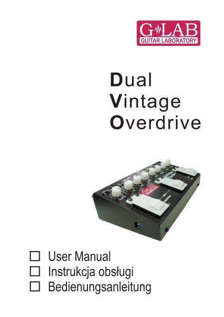
<strong>Dual</strong> <strong>Vintage</strong> <strong>Overdrive</strong> (G <strong>LAB</strong> DVO) is the overdrive type stompbox<br />
effect with two overdriven channels (independent setting of gain, overdrive type<br />
and volume), SOLO volume boosting function and CLEAN tone. DVO can work<br />
as a stompbox connected between a guitar and an amp or as the pre-amp –<br />
connected between a guitar and the power amp.<br />
Basic characteristics:<br />
- classical guitar tube pre-amp emulated by selected FET transistors,<br />
- passive equalizer: TREBLE, MIDDLE, BASS with typical tube amp<br />
characteristics,<br />
- two overdriven channels (CH 1, CH 2) with gain control (GAIN),<br />
boosting and characteristics settable by BOOST A and BOOST B<br />
switches, volume control (VOLUME), enabling to perform from almost<br />
clean tone, through crunch one up to full overdrive,<br />
- SOLO function with adjustable +3 dB or +5 dB boost,<br />
- four working modes of footswitches (set by DIP switches),<br />
- clean tone with volume control (CLEAN),<br />
- independent guitar electronic tuner output (TUNER) with MUTE<br />
function,<br />
- PRE OUT output with buffered direct signal from a guitar,<br />
- FOOT PEDAL input for controlling by the G <strong>LAB</strong> GSC controller or by<br />
a footswitch,<br />
- possibility working in the parallel mode with amp channels and<br />
overdriven channels (CH 1 or CH 2 of DVO), connected directly to a<br />
power amp (skipping pre-amp),<br />
- TREBLE and BASS boost switches post overdriving,<br />
- backlighted footswitches,<br />
- 9V DC power supply.<br />
1
1 - DIP switches<br />
2 - CLEAN tone volume control<br />
3 - SOLO boosting mode switch<br />
4 - 1st and 2nd mode - SOLO mode indicator (full volume),<br />
3rd mode – clean tone indicator (CLEAN),<br />
4th mode – bypass mode indicator<br />
5 - 9V DC power supply socket<br />
6 - Amp output (OUT)<br />
7 - + 3dB TREBLE boosting (post overdriving)<br />
8 - TREBLE control (pre overdriving)<br />
9 - MIDDLE control (pre overdriving)<br />
10 - BASS control (pre overdriving)<br />
11 - FOOT PEDAL input<br />
12 - + 3dB BASS boosting (post overdriving)<br />
13 - First channel (CH1) GAIN control<br />
14 - TUNER output<br />
15 - First channel (CH1) boost switch (BOOST A)<br />
16 - First channel (CH1) indicator<br />
17 - First channel (CH1) VOLUME control<br />
18 - First channel (CH1) boost switch (BOOST B)<br />
19 - Guitar direct signal output (PRE OUT)<br />
20 - Second channel (CH2) GAIN control<br />
21 - Second channel (CH2) boost switch (BOOST A)<br />
22 - Second channel (CH2) indicator<br />
23 - Guitar signal input (IN)<br />
24 - Second channel (CH2) boost switch (BOOST B)<br />
25 - Second channel (CH2) VOLUME control<br />
26 - Right footswitch<br />
27 - Central footswitch<br />
28 - Left footswitch<br />
3
Power supply<br />
DVO should be supplied from external regulated 9V (from 8.7V up to<br />
9.6V) DC power supply, with 80 mA output or more. Before connecting<br />
please check if the connector’s polarisation is proper. DVO is protected<br />
against opposite polarity and overvoltage.<br />
Mode of working selection<br />
In the below table are given footswitches functions in four modes of<br />
working. Mode of working selection is done by No.1 and No.2 DIP switches<br />
located on the left-hand side of the casing.<br />
Mode<br />
DIP switch<br />
position<br />
Left switch<br />
Central<br />
switch<br />
Right switch<br />
1 CH 1* CH 2*<br />
SOLO (CH 2 with full<br />
volume)<br />
2 CH 1* CH 2*<br />
SOLO (active channel<br />
volume change from lowered<br />
to full - or reverse)<br />
3<br />
CLEAN<br />
tone<br />
CH 1<br />
with full<br />
volume<br />
CH 2<br />
with full volume<br />
4<br />
BYPASS<br />
mode<br />
CH 1<br />
with full<br />
volume<br />
CH 2<br />
with full volume<br />
* - with volume -3 dB or -5 dB set by SOLO switch<br />
DIP switch lower position is ON.<br />
Operations of particular modes of working are graphically presented in the<br />
next page table.<br />
4
Mode 1 Mode 2<br />
Mode 3 Mode 4<br />
5
Connecting to a guitar amp<br />
The way of connecting DVO to a guitar amp, an amp type and an amp<br />
controls adjustment affect to a high degree of the final tone effect.<br />
Connecting to the amp guitar input<br />
In such case it is recommended to switch on clean amp channel and to set<br />
flat tone characteristics.<br />
This way of DVO connecting makes that overdriven tone is highly<br />
dependent on an amp tone setting.<br />
Connecting to the amp effects loop input<br />
When the amp is equipped with the serial effect loop (LOOP), it is<br />
recommended to connect OUT output to RETURN effects loop input. In such<br />
case the tone is depending only on amp PRESENCE control if available.<br />
Correction of the tone can be done post overdriving by +3dB BASS and<br />
TREBLE boost switches. If such connected DVO allows to get a good<br />
overdriven ton, you should use parallel connection to the pre-amp (see below).<br />
6
Parallel connection to the amp<br />
The connection with the amp is done by two circuits.<br />
PRE OUT output signal is connected to the amp guitar input.<br />
Output (OUT) signal from DVO should be connected to the amp effects<br />
loop using Switching cable for DVO (product code 00804, ordered separately).<br />
REMARK: In case of connecting Switching cable for DVO, it is required to<br />
connect PRE OUT output to the amp INPUT by the Jack/Jack cable (this cable<br />
assures proper grounding). DVO should be switched to No. 4 mode of working<br />
and for work with Switching cable for DVO (No.3 DIP switch position should be<br />
ON).<br />
DIP switch<br />
position<br />
Connection to an amp<br />
Without „ Switching Cable<br />
for DVO”<br />
Using „ Switching Cable for<br />
DVO”<br />
In this case switching on the first CH1 channel or the second CH2 one will<br />
affect in connecting DVO output directly to the RETURN input of the effects<br />
loop (directly to the power amp skipping pre-amp section). Independence of<br />
amp tones from the overdriven DVO channels is the advantage of such<br />
solution. Tones from the DVO are independent from amp tone settings (except<br />
of PRESENCE control if available).<br />
7
Silent tuning function (MUTE)<br />
Electronic tuner should be connected to the TUNER output. To MUTE<br />
press at the same time left and central footswitches. All indicators will start to<br />
blink. To exit MUTE function should be pressed any footswitch again. The<br />
guitar signal is active all the time at TUNER output.<br />
Connection to the Guitar System Controller G <strong>LAB</strong> GSC<br />
DVO can be controlled by a typical latching type output two-switch foot<br />
pedal connected to the FOOT PEDAL input.<br />
Connecting the FOOT PEDAL input and SW1&2 (or SW3&4) output of<br />
the GSC controller by a Jack/Jack stereo cable enables to control DVO<br />
functions according to the below table.<br />
Mode Switch Indicator is not lit Indicator is lit<br />
1 i 2<br />
3<br />
4<br />
SW1 (or SW3) CH 1 CH 2<br />
SW2 (or SW4) Lowered volume Full volume<br />
SW1 (or SW3) CLEAN tone CH 1 or CH 2<br />
SW2 (or SW4) CH 1 CH 2<br />
SW1 (or SW3) BYPASS CH 1 or CH 2<br />
SW2 (or SW4) CH 1 CH 2<br />
8
Considering the signal path, DVO can be connected between a guitar and<br />
GSC (all effects connected to GSC will be placed post this overdrive), or<br />
between GSC and an amp (all effects connected to GSC will be placed pre this<br />
overdrive), or to the one of GSC loop (DVO can be bypassed and some effects<br />
can be placed pre and some of them post this overdrive).<br />
Rules of overdriving<br />
<strong>Overdrive</strong>n tone is one of the basic tone used by guitar players for playing<br />
different kinds of music.<br />
Slightly overdriven tone is the common used guitar sound. To get slightly<br />
overdriven preset the BOOST A and BOOST B switches should be set to zero<br />
and the GAIN control should be set to minimum. Equalizer controls should be<br />
set at the central position (to “0” value). Tone testing should be done at the<br />
medium volume. Guitar volume controls should be set to maximum. Playing<br />
the guitar, test tone by increasing the GAIN. At some position of the GAIN<br />
knob there will appear the effect of „cutting” sounds with higher amplitude<br />
and later, the effect of adding harmonics to the tone what is the overdrive<br />
effect. It can be clearly heard by programming for example: less GAIN on the<br />
CH 1 than on the CH 2 and more VOLUME on the CH 1 than on the CH 2<br />
(BOOST A and BOOST B switches on both channels should be set<br />
identically) and during songs played these two channels should be switched.<br />
In case of guitars with low signal converters (e.g. single type) this test may<br />
require switching on BOOST A or BOOST B switches.<br />
To get well-defined overdriven tone, one of the active channel BOOST<br />
switches should be switched on. BOOST A and BOOST B offer different<br />
overdriving characteristics. BOOST A supply the tone with more middle and<br />
treble and BOOST B with more bass. To get more bass slightly overdriven tone<br />
only BOOST B should be switched on and GAIN should be lowered to the<br />
required level.<br />
Then can be tested what is the influence of equalizer controls onto the tone.<br />
You should realize that BASS and TREBLE boosting switches (+3dB) are<br />
operating on the overdriven signal. Switching them on produce different effect<br />
than using BASS and TREBLE controls. For typical guitars with humbacker<br />
pickups the best results give setting TREBLE control at -3 dB to 0 dB and<br />
setting on +3 dB TREBLE switch at the same time.<br />
The main factor determining overdriven tone is a frequency characteristics of<br />
amplifying elements between DVO and a speaker, as well as a speaker alone<br />
(understood here as a speaker or a set of speakers in a cabinet). If DVO is<br />
9
connected to the amp clean channel input, it is recommended to set tone<br />
controls of this channel in the following way: BASS to maximum, MIDDLE at<br />
the centre, TREBLE almost to minimum. If DVO is connected to RETURN<br />
input of effects loop then controlling of tone at an amp is limited only to<br />
PRESENCE control (if available).<br />
The element determining tone is a speaker or are speakers (or rather<br />
speaker/speakers model), their quantity, capacity and type of the cabinet.<br />
The largest manufacturers of guitar speakers obtain in their offer wide range<br />
of guitar speakers models. Specially are easily identified speakers<br />
differences for overdriven tones because they obtain a lot of harmonics which<br />
played lauder or more silently make reasonable tone difference. As higher<br />
quantity of speakers as better performance of bass (even at the same amp<br />
power). DVO was designed for working with speakers models usually used in<br />
the high quality amps. The BASS +3dB boost switch allows to increase bass<br />
level to the required one. It is recommended to switch on this boost switch<br />
and eventual excess of bass correct by BASS control.<br />
Some tips from G <strong>LAB</strong> web site: www.glab.com.pl<br />
Too much bass at a neck pickup<br />
Typical problem of many guitars equipped with humbackers is too high<br />
level of bass from a neck pickup comparing with a bridge pickup. If a guitar is<br />
connected to DVO or G <strong>LAB</strong> GSC it is recommended to correct this guitar<br />
electronic circuit (see the diagram at www.glab.com.pl).<br />
Treble disappearing while lowering a volume<br />
Many guitars (with two volume pots) are equipped with an electronic<br />
circuit enabling them to mix in any proportion signals from pickups (even<br />
lowering to zero the volume of one of the pickup do not mute the guitar).<br />
Such a circuit cuts treble while the guitar volume is lowered (as much cut as<br />
longer is the guitar cable) and changes the guitar tone when its volume is<br />
reasonably lowered (the resistance of the pot „short circuit” the pickup). To<br />
solve this problem it is recommended to modify the circuit according to the<br />
diagram at www.glab.com.pl. If after performing this step the effect of cutting<br />
treble still exists, then the reason can be long guitar cable (e.g. 10 meters) or<br />
high parasitic capacitance of this cable (over 1000pF).<br />
10
EMC/EMI & Certificate of conformity<br />
EMC/EMI<br />
This device has been designed and manufactured to conform with directives and<br />
standards in the field of safety operations and electromagnetic interference.<br />
This device uses and can radiate radio frequency energy and, if not installed and<br />
used in accordance with the instructions, may cause harmful interference to radio<br />
communications. However in spite of performing below standards there is no<br />
guarantee that interference will not occur in a particular installation. If this device does<br />
cause harmful interference to radio or television reception which can be determined<br />
by turning the device on and off, the user is encouraged to try to correct the<br />
interference by one or more of the following operations:<br />
● Reorient or relocate the receiving antenna.<br />
● Increase the separation between the device and receiver.<br />
● Connect the device into an outlet on a circuit different from that to which<br />
the receiver is connected.<br />
● Contact with the manufacturer.<br />
● Consult the dealer for help.<br />
Certificate of Conformity<br />
ELZAB S.A., ul. Kruczkowskiego 39, 41-813 Zabrze, Poland,<br />
hereby declares on own responsibility that the following product:<br />
<strong>Dual</strong> <strong>Vintage</strong> <strong>Overdrive</strong> (G <strong>LAB</strong> DVO)<br />
that is covered by this certificate and marked with CE 07 label conforms with<br />
following standards:<br />
PN-EN 60065:2004 Safety requirements for mains operated electronic and<br />
related apparatus for household and similar general use<br />
PN-EN 55103-1:1998 Product family standard for audio, video, audio-visual and<br />
entertainment lighting control apparatus for professional<br />
use. Part 1: Emission.<br />
PN-EN 55103-2:1998 Product family standard for audio, video, audio-visual and<br />
entertainment lighting control apparatus for professional<br />
use. Part 2: Immunity.<br />
with reference to regulations in following directives:<br />
73/23/EEC, 2004/108/EEC<br />
Issued in Zabrze, May 2007<br />
Jerzy Biernat<br />
President of the ELZAB S.A. Board of Directors<br />
11
DO NOT PLACE THIS PRODUCT INTO THE WASTE CONTAINER !<br />
This device is marked with a cross-lined waste container symbol<br />
according to 2002/96/EU Directive on Waste Electric and Electronic<br />
Equipment.<br />
Such marking informs that after usage equipment can not be trashed<br />
together with other household waste.<br />
An user obligation is to return wasted equipment to a party collecting wasted electric and<br />
electronic equipment. Parties collecting such equipment organise a system, including<br />
local collection points, shops and other units, allowing to return such equipment. This<br />
Directive assures an user free of charge utilisation of such delivered equipment.<br />
This device is made of materials which can be recycled or utilised after becoming out of<br />
use. Proper handling of wasted electric and electronic equipment reduce demand for row<br />
materials and contribute in avoiding harmful consequences for environment and health of<br />
people caused by dangerous components and not proper storing and utilising of such<br />
equipment.<br />
Owner Manual, Drawing No.G03INA00<br />
12