HR6 Series.pdf - Genius
HR6 Series.pdf - Genius
HR6 Series.pdf - Genius
You also want an ePaper? Increase the reach of your titles
YUMPU automatically turns print PDFs into web optimized ePapers that Google loves.
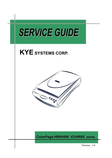
KYE SYSTEMS CORP.<br />
ColorPage-<strong>HR6</strong>/<strong>HR6</strong> V2/<strong>HR6</strong>X series<br />
Version: 1.0
Service<br />
Guide<br />
ColorPage-<strong>HR6</strong>/<strong>HR6</strong> V2/<strong>HR6</strong>X series<br />
Revision History<br />
Version Date Changes<br />
1.0 2001/11/13 Official Release<br />
Version: 1.0<br />
Page 1/59
Service<br />
Guide<br />
ColorPage-<strong>HR6</strong>/<strong>HR6</strong> V2/<strong>HR6</strong>X series<br />
Table of Contents<br />
Revision History............................................................................................................... 1<br />
Table of Contents ............................................................................................................. 2<br />
Chapter 1. Getting Started .......................................................................................... 4<br />
How to Use the Service Guide .................................................................. 4<br />
Conventions Used in this Guide ................................................................ 5<br />
Necessary Tools......................................................................................... 5<br />
Safety Precautions ..................................................................................... 5<br />
Chapter 2. How to Handle Defective Returns............................................................ 7<br />
1.1. Overview ......................................................................................... 7<br />
1.2. Problems .......................................................................................... 8<br />
1.2.1. Main lamp unilluminated ................................................. 9<br />
1.2.2. TPA lamp unilluminated................................................. 10<br />
1.2.3. Unable to Scan ................................................................11<br />
1.2.4. Bad Motor Driving......................................................... 12<br />
1.2.5. Poor Scanning Image ..................................................... 13<br />
1.2.6. Vertical Line ................................................................... 14<br />
1.2.7. Incorrect Initial Scanning Position................................. 15<br />
1.2.8. Incorrect Scanning Center Value.................................... 16<br />
1.2.9. Poor Resolution.............................................................. 17<br />
Chapter 3. Assembly and Disassembly..................................................................... 18<br />
2.1. How to Assembly and Disassembly the Scanner .......................... 18<br />
2.1.1. How to Unlock the Lock Switch.................................... 18<br />
2.1.2. How to Remove the Upper Cover.................................. 19<br />
2.1.3. How to Replace or Clean up the Document glass.......... 21<br />
2.1.4. How to Replace or Clean up the White Calibration Stripe<br />
........................................................................................ 23<br />
2.1.5. How to Replace the Function Button Cable Set............. 24<br />
2.1.6. How to Remove the Sliding Axle and the Timing Belt.. 25<br />
2.1.7. How to Replace the Motor and the Gear Wheel ............ 27<br />
2.1.8. How to Replace the Scan Board..................................... 28<br />
Version: 1.0<br />
Page 2/59
Service<br />
Guide<br />
ColorPage-<strong>HR6</strong>/<strong>HR6</strong> V2/<strong>HR6</strong>X series<br />
2.1.9. How to Replace the CCD Board .................................... 29<br />
2.1.10. How to Clean up the CCD Board Sensor....................... 30<br />
2.1.11. How to Replace the FFC Cable...................................... 31<br />
2.1.12. How to Replace the Lamp and the Inverter.................... 33<br />
2.1.13. How to Replace or Clean up the Mirrors ....................... 35<br />
2.2. How to Assembly and Disassembly TPA Cover............................ 38<br />
2.2.1. How to Replace the TPA Lamp ...................................... 38<br />
2.2.2. How to Replace the TPA Inverter................................... 40<br />
Chapter 4. How to Adjust CCD Resolution and Pixels............................................ 41<br />
3.1. Introduction of Facilities and Tools............................................... 41<br />
3.1.1. Facilities ......................................................................... 41<br />
3.1.2. Tools ............................................................................... 41<br />
3.2. Adjustment Procedures.................................................................. 42<br />
3.2.1. Preparation ..................................................................... 42<br />
3.2.2. How to Adjust the Resolution for Scanner Lens............ 42<br />
3.2.3. How to Adjust CCD Pixel .............................................. 44<br />
3.2.4. How to Adjust the CCD Scanner Center Value.............. 45<br />
Chapter 5. Important Notes ...................................................................................... 46<br />
4.1. Packing requirement for sending the PCB assembly by post........ 46<br />
4.2. Short of spare parts while repairing a scanner............................... 46<br />
Appendix A: Part List .................................................................................................... 47<br />
<strong>HR6</strong> EPP/USB Model .......................................................................... 47<br />
<strong>HR6</strong> V2 EPP/USB Model..................................................................... 49<br />
<strong>HR6</strong>X EPP/USB Model ....................................................................... 51<br />
Appendix B: Disassembly Drawing .............................................................................. 54<br />
<strong>HR6</strong>/<strong>HR6</strong> V2 EPP Model..................................................................... 54<br />
<strong>HR6</strong> USB Model .................................................................................. 55<br />
<strong>HR6</strong> V2 USB Model............................................................................. 56<br />
<strong>HR6</strong>X EPP Model.................................................................................... 57<br />
<strong>HR6</strong>X USB Model .................................................................................. 58<br />
Version: 1.0<br />
Page 3/59
Service<br />
Guide<br />
ColorPage-<strong>HR6</strong>/<strong>HR6</strong> V2/<strong>HR6</strong>X series<br />
Chapter 1.<br />
Getting Started<br />
How to Use the Service Guide<br />
This Service Guide provides instructions and illustrations of servicing scanners related<br />
to ColorPage-<strong>HR6</strong>/<strong>HR6</strong> V2/<strong>HR6</strong>X series scanners. In this section, a basic preparation<br />
for servicing the scanners will be instructed, and therefore please read this section<br />
carefully, before you start servicing the scanners.<br />
Divided into 5 sections, this Service Guide describes an in-depth explanation of<br />
servicing scanners step by step. Each topic may be related with each other; hence you<br />
are highly recommended to read this guide from cover to cover first. After that, you<br />
may go directly to any specific topic that most interests you or meets your immediate<br />
needs.<br />
Chapter 1: How to Handle Defective Returns<br />
Gives a brief working flow for handling defective returns, by which you may<br />
distinguish the causes of the defective returns with the help of these working<br />
flows.<br />
Chapter 2: Assembly and Disassembly<br />
Gives complete instructions and illustrations on how to uninstall and install the<br />
scanners.<br />
Chapter 3: CCD Adjustment<br />
Gives complete instructions and illustrations on how to adjust the lens<br />
resolution and CCD pixel.<br />
Chapter 4: Important Notes<br />
Gives information on how to have your scanner well packed and what to do<br />
when being short of spare parts.<br />
Appendices A & B<br />
Provides part lists and exploded drawings.<br />
Version: 1.0<br />
Page 4/59
Service<br />
Guide<br />
ColorPage-<strong>HR6</strong>/<strong>HR6</strong> V2/<strong>HR6</strong>X series<br />
Conventions Used in this Guide<br />
Attention<br />
Caution<br />
Pay Special Attention: Instructions that are important to<br />
remember and may prevent mistakes<br />
Caution: Information that, if not followed, may result in<br />
damage to the product.<br />
Necessary Tools<br />
• Module Horizontal Resolution<br />
Adjustment tool<br />
• Screwdriver (Cross type)<br />
• Green Seal<br />
• Torsional Driver<br />
• Tweezers<br />
Safety Precautions<br />
The following precautions should be observed in handling the scanner described in this<br />
guide:<br />
• Place the scanner on a flat, level and stable surface.<br />
• Do not place the scanner in environments subject to mist, smoke, vibration,<br />
excessive dust, salty or greasy air, or other corrosive gases and fumes.<br />
• Do not drop or jolt the scanner.<br />
• Do not bump or knock the document glass as it is fragile and could break.<br />
• Do not use another power adapter other than the one enclosed with the<br />
scanner.<br />
• Disconnect the AC adapter and USB Cable. Slide the lock switch to unlock<br />
position<br />
before performing any maintenance procedures on the<br />
scanner.<br />
Version: 1.0<br />
Page 5/59
Service<br />
Guide<br />
ColorPage-<strong>HR6</strong>/<strong>HR6</strong> V2/<strong>HR6</strong>X series<br />
• Do not perform any maintenance with wet hands.<br />
• Prevent foreign substances, such as water, other liquids or chemicals, from<br />
entering the scanner while performing maintenance procedures on the scanner.<br />
Version: 1.0<br />
Page 6/59
Service<br />
Guide<br />
ColorPage-<strong>HR6</strong>/<strong>HR6</strong> V2/<strong>HR6</strong>X series<br />
Chapter 2.<br />
How to Handle Defective Returns<br />
1.1. Overview<br />
Receiving defective<br />
scanners<br />
from customers<br />
Verifying problems &<br />
proceeding necessary tests<br />
Functioning NG<br />
Analyzing possible<br />
malfunction causes<br />
Function NG<br />
Deciding & proceeding<br />
the rectification methods<br />
Functioning OK<br />
Replacing necessary<br />
defective parts<br />
Proceeding tests<br />
to verify if the scanner is<br />
founctioning normally<br />
Function OK<br />
Return the scanners with proper<br />
repackaging to customers<br />
Version: 1.0<br />
Page 7/59
Service<br />
Guide<br />
ColorPage-<strong>HR6</strong>/<strong>HR6</strong> V2/<strong>HR6</strong>X series<br />
1.2. Problems<br />
Item<br />
Problem Descriptions<br />
1.2.1. Main lamp unilluminated<br />
1.2.2. TPA lamp unilluminated<br />
1.2.3.<br />
Unable to Scan (Including: Scanner not functioning, or fail to activate<br />
TWAIN program, etc…)<br />
1.2.4. Bad Motor<br />
1.2.5. Poor Scanning Image<br />
1.2.6. Vertical Line<br />
1.2.7. Incorrect Initial Scanning Position<br />
1.2.8. Incorrect Scanning Center<br />
1.2.9. Poor Resolution<br />
Version: 1.0<br />
Page 8/59
Service<br />
Guide<br />
ColorPage-<strong>HR6</strong>/<strong>HR6</strong> V2/<strong>HR6</strong>X series<br />
Attention<br />
Please follow the numbered sequence marked within parenthesis given in<br />
individual flow chart, in that this is the best-recommended sequence to rectify the<br />
problems.<br />
1.2.1. Main lamp unilluminated<br />
Problem<br />
Main lamp unilluminated<br />
Analyze the<br />
Problem<br />
(1)<br />
Mechanical<br />
(2)<br />
Electronic<br />
(1-1) (1-2) (2-1) (2-2)<br />
Identify the<br />
Problem Causes<br />
Broken or<br />
Defective Lamp<br />
Burned out or<br />
Defective<br />
Inverter<br />
Defective<br />
Scan Board<br />
Defective<br />
CCD Board<br />
Solutions<br />
Replace Lamp<br />
Replace<br />
Inverter<br />
Replace<br />
Scan Board<br />
Replace<br />
CCD Board<br />
Version: 1.0<br />
Page 9/59
Service<br />
Guide<br />
ColorPage-<strong>HR6</strong>/<strong>HR6</strong> V2/<strong>HR6</strong>X series<br />
1.2.2. TPA lamp unilluminated<br />
Problem<br />
TPA lamp unilluminated<br />
Analyze the<br />
Problem<br />
(1) Mechanical<br />
(2) Electronic<br />
(1-1) (1-2) (2-1) (2-2)<br />
Identify the<br />
Problem Causes<br />
Broken or<br />
Defective Lamp<br />
Burned out or<br />
Defective<br />
Inverter<br />
TPA wire is not<br />
attached to Scan<br />
Board<br />
Defective<br />
Scan Board<br />
Solutions<br />
Replace Lamp<br />
Replace<br />
Inverter<br />
Re-attach<br />
the wire<br />
Replace<br />
Scan Board<br />
Version: 1.0<br />
Page 10/59
Service<br />
Guide<br />
ColorPage-<strong>HR6</strong>/<strong>HR6</strong> V2/<strong>HR6</strong>X series<br />
1.2.3. Unable to Scan<br />
Problem<br />
Unable to Scan<br />
Analyze the<br />
Problem<br />
Lock Switch<br />
CCD Board<br />
Scan Board<br />
(1) (2) (3)<br />
Identify the<br />
Problem Causes<br />
Lock Switch<br />
remains in<br />
position<br />
Defective<br />
CCD Board<br />
Defective<br />
Scan Board<br />
Solutions<br />
Slide the<br />
Lock Switch<br />
to<br />
position<br />
Replace<br />
CCD Board<br />
Replace<br />
Scan Board<br />
Version: 1.0<br />
Page 11/59
Service<br />
Guide<br />
ColorPage-<strong>HR6</strong>/<strong>HR6</strong> V2/<strong>HR6</strong>X series<br />
1.2.4. Bad Motor Driving<br />
Problem<br />
Bad Motor Driving<br />
Analyze the<br />
Problem<br />
(1)<br />
Mechanical<br />
(2)<br />
Electronic<br />
(1-1) (1-2) (1-3) (2-1)<br />
Identify the<br />
Problem Causes<br />
Upper Housing,<br />
Base Housing,<br />
or Belt is not in<br />
the right<br />
position<br />
Defective<br />
Motor<br />
Defective<br />
Gear<br />
Defective<br />
Scan Board<br />
Solutions<br />
Re-install<br />
Upper Housing,<br />
Base Housing,<br />
or Belt<br />
Replace Motor<br />
Replace Gear<br />
Replace<br />
Scan Board<br />
Version: 1.0<br />
Page 12/59
Service<br />
Guide<br />
ColorPage-<strong>HR6</strong>/<strong>HR6</strong> V2/<strong>HR6</strong>X series<br />
1.2.5. Poor Scanning Image<br />
Problem<br />
Poor Scanning Image<br />
Analyze the<br />
Problem<br />
(1)<br />
Mechanical (2)<br />
Electronic<br />
(1-1) (1-2) (2-1) (2-2)<br />
Identify the<br />
Problem Causes<br />
Incorrect<br />
CCD Focus<br />
Defective<br />
Reflection<br />
Mirror<br />
Defective<br />
Scan Board<br />
Defective<br />
CCD Board<br />
Solutions<br />
Re-adjust<br />
CCD Pixels<br />
Replace<br />
Reflection<br />
Mirror<br />
Replace<br />
Scan Board<br />
Replace<br />
CCD Board<br />
Version: 1.0<br />
Page 13/59
Service<br />
Guide<br />
ColorPage-<strong>HR6</strong>/<strong>HR6</strong> V2/<strong>HR6</strong>X series<br />
1.2.6. Vertical Line<br />
Problem<br />
Vertical Line<br />
Analyze the<br />
Problem<br />
(1)<br />
Lines in Transparency<br />
(2)<br />
Lines in Colors<br />
(1-1) (1-2) (1-3) (2-1) (2-2) (2-3)<br />
Identify the<br />
Problem Causes<br />
Unclean White<br />
Calibration<br />
Stripe<br />
Unclean<br />
Reflection<br />
Mirror<br />
Assembly<br />
Unclean<br />
Reflection<br />
Mirror<br />
Unclean<br />
Reflection<br />
Mirror<br />
Unclean<br />
CCD Board<br />
Sensor<br />
Defective<br />
CCD Board<br />
Solutions<br />
Clean<br />
up the<br />
Upper<br />
Housing<br />
Clean up<br />
the<br />
Reflection<br />
Mirror<br />
Clean<br />
up the<br />
Mirror<br />
Clean<br />
up the<br />
Mirror<br />
Clean<br />
up the<br />
CCD<br />
Board<br />
Sensor<br />
Replace<br />
The<br />
CCD<br />
Board<br />
Version: 1.0<br />
Page 14/59
Service<br />
Guide<br />
ColorPage-<strong>HR6</strong>/<strong>HR6</strong> V2/<strong>HR6</strong>X series<br />
1.2.7. Incorrect Initial Scanning Position<br />
Problem<br />
Incorrect Initial Scanning Position<br />
Analyze the<br />
Problem<br />
(1)<br />
Cut image found, on<br />
top of the scanned<br />
image<br />
(2)<br />
Blank image found, on<br />
top of the scanned<br />
image<br />
(1-1) (1-2) (2-1) (2-2)<br />
Identify the<br />
Problem Causes<br />
Incorrect<br />
CCD Focus<br />
Deformed<br />
Module<br />
Incorrect<br />
CCD Focus<br />
Deformed<br />
Module<br />
Solutions<br />
Re-adjust<br />
CCD Pixels<br />
Replace<br />
CCD Board<br />
Re-adjust<br />
CCD Pixels<br />
Replace<br />
CCD Board<br />
Version: 1.0<br />
Page 15/59
Service<br />
Guide<br />
ColorPage-<strong>HR6</strong>/<strong>HR6</strong> V2/<strong>HR6</strong>X series<br />
1.2.8. Incorrect Scanning Center Value<br />
Problem<br />
Incorrect Scanning Center Value<br />
Analyze the<br />
Problem<br />
(1)<br />
Scanned image slides<br />
to the Left<br />
(2)<br />
Scanned image slides<br />
to the Right<br />
(1-1) (1-2) (2-1) (2-2)<br />
Identify the<br />
Problem Causes<br />
Incorrect<br />
CCD Focus<br />
Defective CCD<br />
or CCD screw<br />
Incorrect<br />
CCD Focus<br />
Defective CCD<br />
or CCD screw<br />
Solutions<br />
Re-adjust<br />
CCD Scanner<br />
Center<br />
Replace<br />
CCD Board<br />
Re-adjust<br />
CCD Scanner<br />
Center<br />
Replace<br />
CCD Board<br />
Version: 1.0<br />
Page 16/59
Service<br />
Guide<br />
ColorPage-<strong>HR6</strong>/<strong>HR6</strong> V2/<strong>HR6</strong>X series<br />
1.2.9. Poor Resolution<br />
Problem<br />
Poor Resolution<br />
Analyze the<br />
Problem<br />
(1)<br />
Lens<br />
(2)<br />
Reflection Mirror<br />
(1-1) (1-2) (2-1) (2-2)<br />
Identify the<br />
Problem Causes<br />
Lens in<br />
wrong position<br />
Defective Lens<br />
Reflection<br />
Mirror in wrong<br />
position<br />
Wrong<br />
installation of<br />
Reflection<br />
Mirror<br />
Solutions<br />
Re-adjust<br />
CCD Scanner<br />
Center<br />
Replace<br />
CCD Board<br />
Re-adjust<br />
CCD Scanner<br />
Center<br />
Replace<br />
CCD Board<br />
Version: 1.0<br />
Page 17/59
Service<br />
Guide<br />
ColorPage-<strong>HR6</strong>/<strong>HR6</strong> V2/<strong>HR6</strong>X series<br />
Chapter 3.<br />
Assembly and Disassembly<br />
2.1. How to Assembly and Disassembly the Scanner<br />
2.1.1. How to Unlock the Lock Switch<br />
1. Before disassemble the main unit,<br />
slide the Lock Switch to unlock<br />
position. The Lock Switch<br />
is located on the real penal of the<br />
scanner.<br />
Attention<br />
This scanner has a locking<br />
mechanism to hold the Scanner<br />
Module in place during<br />
transportation.<br />
Lock Switch<br />
figure 2.1.1-1<br />
<br />
Please slide the Lock Switch back to<br />
lock position after proper<br />
adjustments have been given. This<br />
will ensure accurate and<br />
problem-free use of the scanner.<br />
Version: 1.0<br />
Page 18/59
Service<br />
Guide<br />
ColorPage-<strong>HR6</strong>/<strong>HR6</strong> V2/<strong>HR6</strong>X series<br />
2.1.2. How to Remove the Upper Cover<br />
Attention<br />
The Upper Housing and the Bottom<br />
Chassis are jointed together mainly by<br />
six points: [a], [b], [c], [d], [e], [f].<br />
[a]<br />
<br />
[b]<br />
figure 2.1.2-1<br />
<br />
[c] [d] [e] [f]<br />
If we open up the Upper Housing and<br />
the Bottom Chassis, in point [a] and<br />
[b] (refer to figure 2.1.2-2,) we will<br />
find a mortise-like and a tenon-like<br />
device (point [X] and [Y]), which<br />
fasten up the Upper Housing and the<br />
Bottom Chassis. In the other 4 points<br />
[c], [d], [e], [f], (refer to figure<br />
2.1.2-2,) the Upper Housing and the<br />
Bottom Chassis are simply jointed<br />
together.<br />
<br />
figure 2.1.2-2<br />
Point [X], Stick Lock<br />
Point [Y], Hook<br />
<br />
figure 2.1.2-3<br />
Version: 1.0<br />
Page 19/59
Service<br />
Guide<br />
ColorPage-<strong>HR6</strong>/<strong>HR6</strong> V2/<strong>HR6</strong>X series<br />
1. To separate the Upper Housing and the<br />
Bottom Chassis, lift up the points [c],<br />
[d], [e], or [f] with both hands or tools,<br />
and then take apart the Upper Housing<br />
from the Bottom Chassis.<br />
2. When points [c], [d], [e], [f] are<br />
successfully separated, use a<br />
screwdriver to release the mortise-like<br />
and a tenon-like device (refer to<br />
figure2.1.2-3)<br />
figure 2.1.2-4<br />
<br />
Attention<br />
When separating the mortise-like<br />
and the tenon-like device, ensure<br />
that the lifting-up direction and<br />
strength is properly, otherwise you<br />
may break the tenon-like device or<br />
the Document Glass.<br />
3. To install the Upper Housing, reverse<br />
the steps shown above.<br />
Attention<br />
When installing the Upper Housing,<br />
ensure that the mortise-like and the<br />
tenon-like device must be aligned<br />
properly before you press down the<br />
Upper Housing.<br />
Version: 1.0<br />
Page 20/59
Service<br />
Guide<br />
ColorPage-<strong>HR6</strong>/<strong>HR6</strong> V2/<strong>HR6</strong>X series<br />
2.1.3. How to Replace or Clean up the Document glass<br />
1 Remove two Glass Stop Blocks [a] and<br />
[b]<br />
[a]<br />
[b]<br />
2 With a screwdriver, press down the left<br />
end of the Glass Stop Block, and then<br />
push it to the right. Then, you may<br />
take the Glass Stop Block out of the<br />
glass holder, and release the space<br />
between the edge of the Document<br />
Glass and the Upper Housing.<br />
Glass Stop Block<br />
figure 2.1.3-1<br />
Glass Holder<br />
3 After the Glass Stop Block is removed,<br />
turn the Document Glass upside down to<br />
let it drop into the space between the<br />
edge of the Document Glass and the<br />
upper cover as mentioned in step 2.<br />
figure 2.1.3-2<br />
figure 2.1.3-3<br />
Version: 1.0<br />
Page 21/59
Service<br />
Guide<br />
ColorPage-<strong>HR6</strong>/<strong>HR6</strong> V2/<strong>HR6</strong>X series<br />
4 Erect the Document Glass as shown in<br />
figure 2.1.3-4.<br />
5 Gently take out the Document Glass.<br />
figure 2.1.3-4<br />
6 Clean up the Document Glass with<br />
cotton cloth and water.<br />
figure 2.1.3-5<br />
Caution<br />
Do not clean up the Document Glass<br />
with any chemical.<br />
7 To install the Document Glass, reverse<br />
the steps shown above.<br />
Version: 1.0<br />
Page 22/59
Service<br />
Guide<br />
ColorPage-<strong>HR6</strong>/<strong>HR6</strong> V2/<strong>HR6</strong>X series<br />
2.1.4. How to Replace or Clean up the White Calibration Stripe<br />
1 Remove the Document Glass.<br />
2 Clean up the White Calibration Stripe<br />
with cotton cloth and water.<br />
figure 2.1.4-1<br />
Caution<br />
Do not clean up the White Calibration<br />
stripe with any chemical.<br />
3 Re-install the Document Glass.<br />
figure 2.1.4-2<br />
Version: 1.0<br />
Page 23/59
Service<br />
Guide<br />
ColorPage-<strong>HR6</strong>/<strong>HR6</strong> V2/<strong>HR6</strong>X series<br />
2.1.5. How to Replace the Function Button Cable Set<br />
1 Loosen the screw [a] on the Function<br />
Button Cable Set.<br />
[a] screw<br />
2 Pull up the cable which is attached on<br />
point [b], [c], [d], [e].<br />
figure 2.1.5-1<br />
[b] [c] [d] [e]<br />
3 Disconnect the connecter [f] that is<br />
connected to the Scan Board.<br />
figure 2.1.5-2<br />
[f]<br />
4 To install the Function Button Cable Set,<br />
reverse the steps shown above.<br />
figure 2.1.5-3<br />
Version: 1.0<br />
Page 24/59
Service<br />
Guide<br />
ColorPage-<strong>HR6</strong>/<strong>HR6</strong> V2/<strong>HR6</strong>X series<br />
2.1.6. How to Remove the Sliding Axle and the Timing Belt<br />
1 Push the Siding Axle holder [a] to the<br />
left and pull up the Sliding Axle [b] as<br />
shown in figure 2.1.6-1.<br />
[b] Pull up<br />
[a] Push to the left<br />
figure 2.1.6-1<br />
2 Push in the Gear Wheel [a] and take out<br />
the Timing Belt spring [b].<br />
[b] Take out the belt<br />
[a] Push in<br />
figure 2.1.6-2<br />
Version: 1.0<br />
Page 25/59
Service<br />
Guide<br />
ColorPage-<strong>HR6</strong>/<strong>HR6</strong> V2/<strong>HR6</strong>X series<br />
3<br />
Attention<br />
The Timing Belt has been fixed on the<br />
belt-fixed point of Scanner Module<br />
with green seal (as shown in figure<br />
2.1.6-3, point [A].) Please do not<br />
pull out the Timing Belt with violence,<br />
in that it may cause the belt-fixed<br />
point cracked from the Scanner<br />
Module.<br />
To replace the Timing Belt, place<br />
alcohol in drops to dissolve green seal.<br />
figure 2.1.6-3<br />
After green seal was completely<br />
dissolved, and then you may use a<br />
tweezers to take off the Timing Belt<br />
from Scanner Module.<br />
4 To install the Sliding Axle and the<br />
Timing Belt, reverse the steps shown<br />
above.<br />
Magnify the point of Belt-fixed (A)<br />
Timing<br />
Belt<br />
Attention<br />
Ensure that the Timing Belt is<br />
installed with the correct direction<br />
(as shown in figure 2.1.6-4)<br />
Outside of<br />
belt-fixed<br />
point<br />
Outside of<br />
belt-fixed<br />
point<br />
figure 2.1.6-4<br />
Version: 1.0<br />
Page 26/59
Service<br />
Guide<br />
ColorPage-<strong>HR6</strong>/<strong>HR6</strong> V2/<strong>HR6</strong>X series<br />
2.1.7. How to Replace the Motor and the Gear Wheel<br />
1 Dissolve the green seal on the screws.<br />
Loosen the screws [a], [b] from fixed<br />
plate of idle arm with a screwdriver.<br />
[c] Motor connecter<br />
Loosen the Motor, and disconnect the<br />
connecter [c] that is connected to the<br />
Scan Board.<br />
2 To remove the Gear Wheel, take out the<br />
E Ring [d] with a tweezers.<br />
[d] E Ring<br />
figure 2.1.7-1<br />
[a], [b] screw<br />
Remove the Gear Wheel.<br />
figure 2.1.7-2<br />
3 To install the motor and gear wheel,<br />
reverse the steps shown above.<br />
figure 2.1.7-3<br />
Version: 1.0<br />
Page 27/59
Service<br />
Guide<br />
ColorPage-<strong>HR6</strong>/<strong>HR6</strong> V2/<strong>HR6</strong>X series<br />
2.1.8. How to Replace the Scan Board<br />
1 Loosen the screws [a], [b] on the Scan<br />
Board.<br />
[a], [b] screws<br />
2 Disconnect the FFC Cable [c].<br />
Disconnect the connector of [d] the<br />
Function Button Cable Set and [e] the<br />
Motor.<br />
Gently pull up the Scan Board<br />
figure 2.1.8-1<br />
[c] FFC cable<br />
[d], [e] connectors<br />
Pull up<br />
3 To install the Scan Board, ensure that<br />
you have re-connected the FFC cable<br />
before you place the Scan Board back to<br />
its original place; and both connecting<br />
side of the FFC Cable and Scan Board<br />
must face each other, or it may result<br />
system failure.<br />
(See 2.1.11. How to Replace the FFC<br />
Cable for details about the FFC Cable<br />
connecting side.)<br />
figure 2.1.8-2<br />
Reverse the steps shown above to install<br />
the scan board.<br />
Version: 1.0<br />
Page 28/59
Service<br />
Guide<br />
ColorPage-<strong>HR6</strong>/<strong>HR6</strong> V2/<strong>HR6</strong>X series<br />
2.1.9. How to Replace the CCD Board<br />
1 Dissolve the green seal on the screws<br />
[a], [b] on the scan board before you<br />
loosen them.<br />
Disconnect the connector of Inverter [c].<br />
[a]<br />
screws<br />
[b]<br />
2 Disconnect the connector of Inverter [c].<br />
Disconnect the FFC Cable [d].<br />
figure 2.1.9-1<br />
disconnect<br />
the FFC cable<br />
[d]<br />
[c]<br />
disconnect<br />
the connector<br />
3 When installing the CCD Board, ensure<br />
that both connecting side of the FFC<br />
Cable and CCD Board must face each<br />
other, or it may result system failure.<br />
(See 2.1.11. How to Replace the FFC<br />
Cable for details about the FFC Cable<br />
connecting side.)<br />
Reverse the steps shown above to install<br />
the Scan Board.<br />
figure 2.1.9-2<br />
Attention<br />
It is necessary to place a screen<br />
protecting sheet onto the sensor of<br />
the replaced CCD Board. For<br />
details, please refer Chapter 4,<br />
Important Notes.<br />
Version: 1.0<br />
Page 29/59
Service<br />
Guide<br />
ColorPage-<strong>HR6</strong>/<strong>HR6</strong> V2/<strong>HR6</strong>X series<br />
2.1.10. How to Clean up the CCD Board Sensor<br />
1 Take out the CCD Board<br />
2 Clean up the CCD Board Sensor with<br />
lens cleaning cloth. However, wiping<br />
the CCD Board Sensor is not<br />
recommended, in that it may result<br />
scratches.<br />
figure 2.1.10-2<br />
Caution<br />
Do not clean up the CCD Board<br />
Sensor with any chemical.<br />
3 To install the CCD Board, ensure that<br />
both connecting side of the FFC Cable<br />
and CCD Board must face each other,<br />
or it may result system failure. (See<br />
2.1.11. How to Replace the FFC Cable<br />
for details about the FFC Cable<br />
connecting side.)<br />
Reverse the steps shown above to install<br />
the Scan Board.<br />
Version: 1.0<br />
Page 30/59
Service<br />
Guide<br />
ColorPage-<strong>HR6</strong>/<strong>HR6</strong> V2/<strong>HR6</strong>X series<br />
2.1.11. How to Replace the FFC Cable<br />
1 Pull out one end of the FFC Cable,<br />
which is attached to the Scan Board.<br />
Attention<br />
While pulling out the FFC Cable,<br />
make sure that it is pull out with<br />
steady strength, otherwise, you may<br />
bend the FFC Cable, and result<br />
system failure.<br />
figure 2.1.11-1<br />
2 Pull out another end of the FFC Cable,<br />
which is attached to the CCD Board<br />
steady strength<br />
figure 2.1.11-2<br />
Version: 1.0<br />
Page 31/59
Service<br />
Guide<br />
ColorPage-<strong>HR6</strong>/<strong>HR6</strong> V2/<strong>HR6</strong>X series<br />
3 When installing the FFC Cable, ensure<br />
that both connecting side on the FFC<br />
Cable (shown in figure 2.1.11-3) and<br />
scan board or CCD Board (shown in<br />
figure 2.1.11-5) must face each other,<br />
otherwise, it may result system failure.<br />
Connecting side<br />
Reverse the steps shown above to install<br />
the FFC Cable.<br />
2.1.11-3<br />
reverse side<br />
2.1.11-4<br />
Connecting side UP<br />
2.1.11-5<br />
Version: 1.0<br />
Page 32/59
Service<br />
Guide<br />
ColorPage-<strong>HR6</strong>/<strong>HR6</strong> V2/<strong>HR6</strong>X series<br />
2.1.12. How to Replace the Lamp and the Inverter<br />
Caution<br />
Lamps are fragile and could break;<br />
please pay more attention while<br />
replacing them.<br />
Lamp connector<br />
1<br />
Disconnect the Lamp Connector that is<br />
attached to the Inverter.<br />
2 Pull out the Lamp wire gently.<br />
figure 2.1.12-1<br />
Pull out one end of the Lamp where a<br />
protection rubber is covered, and then<br />
the other end. (shown in figure 2.1.12-3)<br />
figure 2.1.12-2<br />
figure 2.1.12-3<br />
Version: 1.0<br />
Page 33/59
Service<br />
Guide<br />
ColorPage-<strong>HR6</strong>/<strong>HR6</strong> V2/<strong>HR6</strong>X series<br />
3 To remove the Inverter, first dissolve the<br />
green seal on point [a], and then take out<br />
the Inverter.<br />
[a]<br />
4 To install the Lamp and the Inverter,<br />
reverse the steps shown above<br />
figure 2.1.12-4<br />
Version: 1.0<br />
Page 34/59
Service<br />
Guide<br />
ColorPage-<strong>HR6</strong>/<strong>HR6</strong> V2/<strong>HR6</strong>X series<br />
2.1.13. How to Replace or Clean up the Mirrors<br />
1<br />
Caution<br />
Mirrors are fragile and could break;<br />
please pay more attention while<br />
replacing them.<br />
Total four Mirrors in different sizes are<br />
installed in the Scanner Module.<br />
Mirror [A] are fixed in the groove on the<br />
module with black seal and Mirror Fix<br />
Clip.<br />
Mirror [C]<br />
Mirror [B]<br />
Mirror [D]<br />
Mirror [A]<br />
figure 2.1.13-1<br />
Mirror [B], [C], [D] are fixed in the<br />
Scanner Module with black seal only;<br />
Mirror [A]<br />
Fixed with<br />
Mirror Fix Clip<br />
2 Before removing these Mirrors, dissolve<br />
black seal with alcohol first.<br />
figure 2.1.13-2<br />
Take out the Mirror Fix Clips. (for mirror<br />
[A] only).<br />
Mirror Fix Clip<br />
Pull out the Mirrors with a tweezers.<br />
figure 2.1.13-3<br />
Version: 1.0<br />
Page 35/59
Service<br />
Guide<br />
ColorPage-<strong>HR6</strong>/<strong>HR6</strong> V2/<strong>HR6</strong>X series<br />
3 Clean up the Mirrors with cotton cloth<br />
and water.<br />
Caution<br />
Do not clean up the Mirrors with any<br />
chemical.<br />
4 When installing Mirror A, use one hand<br />
to insert the mirror into the position that<br />
it belongs to, and the other hand to hold<br />
the module and prevent the mirror from<br />
falling down from the groove on the<br />
module (as shown in figure 2.1.13-4.)<br />
Mirror [A]<br />
Once Mirror A has inserted, place two<br />
Mirror Fix Clips to both side of the<br />
groove, and then place black seal onto it<br />
(as shown in figure 2.1.13-5.)<br />
figure 2.1.13-4<br />
Attention<br />
Please be noted that the Mirror Fix<br />
Clips must be inserted with a proper<br />
direction (shown as below.)<br />
mirror fix clips<br />
figure 2.1.13-5<br />
Version: 1.0<br />
Page 36/59
Service<br />
Guide<br />
ColorPage-<strong>HR6</strong>/<strong>HR6</strong> V2/<strong>HR6</strong>X series<br />
5 To install Mirror [B], [C], and [D], place<br />
the Mirrors into the groove they belong<br />
to, and then place black seal onto both<br />
ends of the groove.<br />
figure 2.1.13-6<br />
Attention<br />
To install the Mirrors, ensure that the<br />
reflection side must face inward of the<br />
Scanner Module.<br />
<br />
<br />
<br />
<br />
<br />
<br />
Version: 1.0<br />
Page 37/59
Service<br />
Guide<br />
ColorPage-<strong>HR6</strong>/<strong>HR6</strong> V2/<strong>HR6</strong>X series<br />
2.2. How to Assembly and Disassembly TPA Cover<br />
2.2.1. How to Replace the TPA Lamp<br />
1 Take off the spongy as shown in figure<br />
2.2.1-1<br />
2 Loosen the screws [a], [b], [c], and [d]<br />
with a screwdriver.<br />
[a]<br />
[b]<br />
figure 2.2.1-1<br />
[c]<br />
[d]<br />
3 Dissolve the green seal with alcohol, and<br />
then take out the plastic board.<br />
figure 2.2.1-2<br />
Green seal<br />
Green seal<br />
figure 2.2.1-3<br />
Version: 1.0<br />
Page 38/59
Service<br />
Guide<br />
ColorPage-<strong>HR6</strong>/<strong>HR6</strong> V2/<strong>HR6</strong>X series<br />
4 Loosen the screws [e] and [f] with a<br />
screwdriver, and then open up the<br />
Transformer Cover.<br />
[e]<br />
[f]<br />
5 Disconnect the connector of the TPA<br />
Lamp [e].<br />
[e]<br />
figure 2.2.1-4<br />
6 Replace the TPA Lamp.<br />
figure 2.2.1-5<br />
7 To install the TPA Lamp, reverse the<br />
steps shown above.<br />
figure 2.2.1-6<br />
Version: 1.0<br />
Page 39/59
Service<br />
Guide<br />
ColorPage-<strong>HR6</strong>/<strong>HR6</strong> V2/<strong>HR6</strong>X series<br />
2.2.2. How to Replace the TPA Inverter<br />
1 Loosen the screws [a] and [b] with a<br />
screwdriver, and then open up the<br />
Transformer Cover.<br />
[a]<br />
[b]<br />
2 Loosen the screws [c] and [d].<br />
figure 2.2.2-1<br />
Disconnect the connector of the TPA<br />
Lamp<br />
[c]<br />
[d]<br />
3<br />
Disconnect the connector of the TPA<br />
Lamp [e], and the connector of the TPA<br />
Inverter Power Cable [f].<br />
[e]<br />
figure 2.2.2-2<br />
Replace the TPA Inverter.<br />
4<br />
To install the TPA Inverter, reverse steps<br />
shown above.<br />
[f]<br />
figure 2.2.2-3<br />
Version: 1.0<br />
Page 40/59
Service<br />
Guide<br />
ColorPage-<strong>HR6</strong>/<strong>HR6</strong> V2/<strong>HR6</strong>X series<br />
Chapter 4. How to Adjust CCD Resolution and Pixels<br />
3.1. Introduction of Facilities and Tools<br />
3.1.1. Facilities<br />
1<br />
2<br />
Computer<br />
CCD Adjustment Software<br />
figure 3.1.1-1<br />
3.1.2. Tools<br />
1<br />
2<br />
3<br />
4<br />
5<br />
6<br />
Module Horizontal Resolution<br />
Adjustment tool<br />
Screwdriver (Cross type)<br />
Green Seal<br />
Torsional Driver<br />
Tweezers<br />
figure 3.1.2-1<br />
Version: 1.0<br />
Page 41/59
Service<br />
Guide<br />
ColorPage-<strong>HR6</strong>/<strong>HR6</strong> V2/<strong>HR6</strong>X series<br />
3.2. Adjustment Procedures<br />
3.2.1. Preparation<br />
1<br />
Connecting the scanner to the computer.<br />
2<br />
Activating the adjustment program for<br />
either EPP_CCD or USB_CCE.<br />
3<br />
Reset the system before proceeding any<br />
adjustment.<br />
figure 3.2.1-1<br />
Adjustment Screen<br />
3.2.2. How to Adjust the Resolution for Scanner Lens<br />
1<br />
With a tweezers, move the Scanner Lens<br />
forward or backward, or rotate the Lens.<br />
2<br />
Using a Module Horizontal Resolution<br />
Adjustment tool to adjust the Lens<br />
resolution.<br />
Attention<br />
The center value for each Module<br />
Horizontal Resolution Adjustment<br />
tool is between +10 to –10.<br />
figure 3.2.1-1<br />
Version: 1.0<br />
Page 42/59
Service<br />
Guide<br />
ColorPage-<strong>HR6</strong>/<strong>HR6</strong> V2/<strong>HR6</strong>X series<br />
3 Adjusting the Scanner Lens and<br />
observing the computer screen till the<br />
waveform shown in the computer screen<br />
has reached its maximum wavelength.<br />
4 When the proper adjustments have been<br />
done, fix the Scanner Lens with green<br />
seal.<br />
figure 3.2.1-2<br />
figure 3.2.1-4<br />
Version: 1.0<br />
Page 43/59
Service<br />
Guide<br />
ColorPage-<strong>HR6</strong>/<strong>HR6</strong> V2/<strong>HR6</strong>X series<br />
3.2.3. How to Adjust CCD Pixel<br />
1<br />
Place a Module Horizontal Resolution<br />
Adjustment tool onto the Scanner<br />
Module (figure 4.2.3-1)<br />
Module Horizontal<br />
Resolution Adjustment tool<br />
2<br />
Loosen the screws that fix the CCD<br />
Board.<br />
3<br />
Slightly adjust the position of CCD<br />
Board till the waveform shown in the<br />
computer screen has reached its<br />
maximum wavelength.<br />
figure 3.2.3-1<br />
4<br />
Fasten the screws temporally, but do not<br />
solidly fasten the screws.<br />
Version: 1.0<br />
Page 44/59
Service<br />
Guide<br />
ColorPage-<strong>HR6</strong>/<strong>HR6</strong> V2/<strong>HR6</strong>X series<br />
3.2.4. How to Adjust the CCD Scanner Center Value<br />
1<br />
Loosen the screws that fix the CCD<br />
Board.<br />
Module Horizontal<br />
Resolution Adjustment tool<br />
2<br />
With one hand to adjust the Scanner<br />
Center slightly to the right or left.<br />
Attention<br />
The Scanner Center value for the<br />
Module Horizontal Resolution<br />
Adjustment tool is between +10<br />
to –10.<br />
figure 3.2.4-1<br />
3<br />
After the Scanner Center is set, hold the<br />
CCD Board with one hand, and then<br />
adjust the horizontal pixel slightly up or<br />
down.<br />
4<br />
The Module Horizontal Resolution<br />
Adjustment tool is not necessarily to be<br />
used while adjusting the scanner center<br />
and the horizontal pixel (shown as figure<br />
3.2.4-2)<br />
figure 3.2.4-2<br />
5<br />
When adjustments have been done, and<br />
then you may solidly fasten the screws.<br />
6<br />
Place green seal onto the screws, and<br />
re-install the Scanner Module back to its<br />
original position.<br />
Version: 1.0<br />
Page 45/59
Service<br />
Guide<br />
ColorPage-<strong>HR6</strong>/<strong>HR6</strong> V2/<strong>HR6</strong>X series<br />
Chapter 5.<br />
Important Notes<br />
4.1. Packing requirement for sending the PCB assembly by post<br />
PCB assembly is a kind of sophisticated electronic circuit board. A scanner<br />
mainly includes the following items: Scan Board, CCD Board, Switch Board,<br />
Panel Board, etc… Therefore, well packing will be required when sending them<br />
by post.<br />
• Some sophisticated IC components are mounted on the PCB assembly, hence<br />
it is necessary to pack each PCB assembly with a separate static protecting<br />
beg, in order to avoid static electricity.<br />
• CCD sensor is the most important component on the CCD Board, hence,<br />
CCD sensor must be covered by a protecting sheet (shown as below) when<br />
mailing it, in order to prevent from scratch.<br />
CCD sensor, covered by a screen<br />
protecting sheet<br />
• Reliable external packing is also very important when sending the PCB<br />
assembly by post, in that it would avoid unnecessarily lost or damage.<br />
4.2. Short of spare parts while repairing a scanner<br />
If you are short of spare parts when you have some scanners waiting to be<br />
repaired, it would be recommended to take the necessary parts from one scanner,<br />
so that you may have the as many as scanners be repaired and sent back to your<br />
customer, and left only one or few scanners waiting for spare parts sending from<br />
Plustek.<br />
Version: 1.0<br />
Page 46/59
Service<br />
Guide<br />
ColorPage-<strong>HR6</strong>/<strong>HR6</strong> V2/<strong>HR6</strong>X series<br />
Appendix A: Part List<br />
<strong>HR6</strong> EPP/USB Model<br />
Item<br />
Description<br />
Part Number<br />
(EPP Model)<br />
Part Number<br />
(USB Model)<br />
1 Double-sided Adhesive Tape 13-A7-Q3351-A 13-A7-Q3351-A<br />
2 TPA Cover 13-B6-A6051-A 13-B6-A6051-A<br />
3 Transformer Cover 13-B6-A1081-A 13-B6-A1081-A<br />
4 TPA Lamp Stand 13-B6-08011-A 13-B6-08011-A<br />
5 Reflection Aluminum Foil Sticker 13-02-51181-A 13-02-51181-A<br />
6 Double-sided Adhesive Tape 13-A7-Q3211-A 13-A7-Q3211-A<br />
7 CCF Lamp A (TPA Lamp) 10-04-031-A 10-04-031-A<br />
8 Acrylic Board 13-02-56061-A 13-02-56061-A<br />
9 Sponge 13-02-52121-A 13-02-52121-A<br />
10 TPA Cover Sheet 13-A7-T21021-A 13-A7-T21021-A<br />
11 Lamp Inverter 14-02-022-A 14-02-022-A<br />
12 Isolation Sheet 13-A6-T2521-A 13-A6-T2521-A<br />
13 Wire Harness 12-01-022-A 12-01-022-A<br />
14 Slide Holder 13-A7-T2111-A 13-A7-T2111-A<br />
15 Negative Holder 21-2A9-002312 21-2A9-002312<br />
16 Button A 13-B6-02021-A 13-B6-02021-A<br />
17 Upper Housing 13-B6-A1071-A 13-B6-A1071-A<br />
18 LED 13-02-56091-A 13-02-56091-A<br />
19 Button B 13-B6-02031-A 13-B6-02031-A<br />
20 Glass Stop Block 13-A1-A8051-A 13-A1-A8051-A<br />
21 Document glass 19-01-131-A 19-01-131-A<br />
22 Security Lock Assist Metal Part 15-A1-A2661-A 15-A1-A2661-A<br />
23 Security Lock 13-A1-99011-A 13-A1-99011-A<br />
24 White Calibration Stripe 13-A7-T3431-A 13-A7-T3431-A<br />
25 CCF Lamp B (Main Lamp) 10-04-027-A 10-04-027-A<br />
26 Reflection Film 13-A7-T3441-A 13-A7-T3441-A<br />
27 CCD Board 23-2D1-0921-TSB 23-2D1-0921-TSB<br />
28 Washer 13-A7-05011-A 13-A7-05011-A<br />
Version: 1.0<br />
Page 47/59
Service<br />
Guide<br />
ColorPage-<strong>HR6</strong>/<strong>HR6</strong> V2/<strong>HR6</strong>X series<br />
Item<br />
Description<br />
Part Number<br />
(EPP Model)<br />
Part Number<br />
(USB Model)<br />
29 Scan Module 21-2D3-004711 21-2D3-004711<br />
30 Reflection Mirror A1 19-02-162-A 19-02-162-A<br />
31 Mirror Fix Clip 15-A5-T4431-A 15-A5-T4431-A<br />
32 Lens 19-03-311-A 19-03-311-A<br />
33 Move Slider 13-A2-A8021-A 13-A2-A8021-A<br />
34 Reflection Mirror B 19-02-171-A 19-02-171-A<br />
35 Lamp Inverter 14-02-021-A 14-02-021-A<br />
36 Stepping Motor 14-04-030-B 14-04-030-B<br />
37 Motor Plate 15-A1-A2651-A 15-A1-A2651-A<br />
38 E Ring 15-03-77011-A 15-03-77011-A<br />
39 Pulley A (Pulley #2026 Assembly) 21-2C1-0035T1 21-2C1-0035T1<br />
40 Pulley B 13-A2-A7381-A 13-A2-A7381-A<br />
41 Gear Shaft B 15-A6-R1021-A 15-A6-R1021-A<br />
42 Spring A 15-A5-T7181-A 15-A5-T7181-A<br />
43 Gear Shaft A 15-A6-R1011-A 15-A6-R1011-A<br />
44 Scan Board 23-2D8-0911-TSB 23-2D8-0911-TSB<br />
45 Bottom Chassis 13-B6-A3171-A 13-B6-A3171-A<br />
46 Rubber Foot 13-A8-P1021-A 13-A8-P1021-A<br />
47 Motion Shaft 15-A4-R1161-A 15-A4-R1161-A<br />
48 Timing Belt 13-01-07121-B 13-01-07121-B<br />
49 Pulley Assembly 21-231-003411 21-231-003411<br />
50 Idle Roller Plate 15-A1-A2751-A 15-A1-A2751-A<br />
51 Spring B 15-A5-T7071-A 15-A5-T7071-A<br />
52 FFC 22 Pin 485mm 12-06-226-A 12-06-226-A<br />
53 Switch Board 23-2D6-0932-TSB 23-2 D6-0932-TSB<br />
54 EMI Core 13-A8-57041-A 13-A8-57041-A<br />
55 Lens Anti-dazzling Screen A 13-B3-T2081-A 13-B3-T2081-A<br />
56 Rubber Protector 13-A8-R1181-A 13-A8-R1181-A<br />
57 Spring Washer 13-A6-05011-A 13-A6-05011-A<br />
58 Lens Anti-dazzling Screen B 13-B3-T2111-A 13-B3-T2111-A<br />
Version: 1.0<br />
Page 48/59
Service<br />
Guide<br />
ColorPage-<strong>HR6</strong>/<strong>HR6</strong> V2/<strong>HR6</strong>X series<br />
<strong>HR6</strong> V2 EPP/USB Model<br />
Item<br />
Description<br />
Part Number<br />
(EPP Model)<br />
Part Number<br />
(USB Model)<br />
1 Double-sided Adhesive Tape 13-A7-Q3351-A 13-A7-Q3351-A<br />
2 TPA Cover 13-B6-A6051-A 13-B6-A6051-A<br />
3 Transformer Cover 13-B6-A1081-A 13-B6-A1081-A<br />
4 TPA Lamp Stand 13-B6-08011-A 13-B6-08011-A<br />
5 Reflection Aluminum Foil Sticker 13-02-51181-A 13-02-51181-A<br />
6 Double-sided Adhesive Tape 13-A7-Q3211-A 13-A7-Q3211-A<br />
7 CCF Lamp A (TPA Lamp) 10-04-031-A 10-04-031-A<br />
8 Acrylic Board 13-02-56061-A 13-02-56061-A<br />
9 Sponge 13-02-52121-A 13-02-52121-A<br />
10 TPA Cover Sheet 13-A7-T21021-A 13-A7-T21021-A<br />
11 Lamp Inverter 14-02-022-A 14-02-022-A<br />
12 Isolation Sheet 13-A6-T2521-A 13-A6-T2521-A<br />
13 Wire Harness 12-01-022-A 12-01-022-A<br />
14 Slide Holder 13-A7-T2111-A 13-A7-T2111-A<br />
15 Negative Holder 21-2A9-002312 21-2A9-002312<br />
16 Button A 13-B6-02021-A 13-B6-02021-A<br />
17 Upper Housing 13-B6-A1071-A 13-B6-A1071-A<br />
18 LED 13-02-56091-A 13-02-56091-A<br />
19 Button B 13-B6-02031-A 13-B6-02031-A<br />
20 Glass Stop Block 13-A1-A8051-A 13-A1-A8051-A<br />
21 Document glass 19-01-131-A 19-01-131-A<br />
22 Security Lock Assist Metal Part 15-A1-A2661-A 15-A1-A2661-A<br />
23 Security Lock 13-A1-99011-A 13-A1-99011-A<br />
24 White Calibration Stripe 13-A7-T3431-A 13-A7-T3431-A<br />
25 CCF Lamp B (Main Lamp) 10-04-027-A 10-04-027-A<br />
26 Reflection Film 13-A7-T3441-A 13-A7-T3441-A<br />
27 CCD Board 23-2D1-0921-TSB 23-2D1-0921-TSB<br />
28 Washer 13-A7-05011-A 13-A7-05011-A<br />
29 Scan Module 21-2D3-004711 21-2D3-004711<br />
30 Reflection Mirror A1 19-02-162-A 19-02-162-A<br />
Version: 1.0<br />
Page 49/59
Service<br />
Guide<br />
ColorPage-<strong>HR6</strong>/<strong>HR6</strong> V2/<strong>HR6</strong>X series<br />
Item<br />
Description<br />
Part Number<br />
(EPP Model)<br />
Part Number<br />
(USB Model)<br />
31 Mirror Fix Clip 15-A5-T4431-A 15-A5-T4431-A<br />
32 Lens 19-03-311-A 19-03-311-A<br />
33 Move Slider 13-A2-A8021-A 13-A2-A8021-A<br />
34 Reflection Mirror B 19-02-171-A 19-02-171-A<br />
35 Lamp Inverter 14-02-021-A 14-02-021-A<br />
36 Stepping Motor 14-04-030-B 14-04-030-B<br />
37 Motor Plate 15-A1-A2651-A 15-A1-A2651-A<br />
38 E Ring 15-03-77011-A 15-03-77011-A<br />
39 Pulley A (Pulley #2026 Assembly) 21-2C1-0035T1 21-2C1-0035T1<br />
40 Pulley B 13-A2-A7381-A 13-A2-A7381-A<br />
41 Gear Shaft B 15-A6-R1021-A 15-A6-R1021-A<br />
42 Spring A 15-A5-T7181-A 15-A5-T7181-A<br />
43 Gear Shaft A 15-A6-R1011-A 15-A6-R1011-A<br />
44 Scan Board 23-2D8-0911-TSB 23-2E9-0911-TSB<br />
45 Bottom Chassis 13-B6-A3171-A 13-B6-A3171-A<br />
46 Rubber Foot 13-A8-P1021-A 13-A8-P1021-A<br />
47 Motion Shaft 15-A4-R1161-A 15-A4-R1161-A<br />
48 Timing Belt 13-01-07121-B 13-01-07121-B<br />
49 Pulley Assembly 21-231-003411 21-231-003411<br />
50 Idle Roller Plate 15-A1-A2751-A 15-A1-A2751-A<br />
51 Spring B 15-A5-T7071-A 15-A5-T7071-A<br />
52 FFC 22 Pin 485mm 12-06-226-A 12-06-226-A<br />
53 Switch Board 23-2D6-0932-TSB 23-2 D6-0930-TSB<br />
54 EMI Core 13-A8-57041-A 13-A8-57041-A<br />
55 Lens Anti-dazzling Screen A 13-B3-T2081-A 13-B3-T2081-A<br />
56 Rubber Protector 13-A8-R1181-A 13-A8-R1181-A<br />
57 Spring Washer 13-A6-05011-A 13-A6-05011-A<br />
58 Lens Anti-dazzling Screen B 13-B3-T2111-A 13-B3-T2111-A<br />
Version: 1.0<br />
Page 50/59
Service<br />
Guide<br />
ColorPage-<strong>HR6</strong>/<strong>HR6</strong> V2/<strong>HR6</strong>X series<br />
<strong>HR6</strong>X EPP/USB Model<br />
Item<br />
Description<br />
Part Number<br />
(EPP Model)<br />
Part Number<br />
(USB Model)<br />
1 Lens Anti-dazzling Screen A 13-B3-T2081-A 13-B3-T2081-A<br />
2 TPA Cover 13-B6-A6051-A 13-B6-A6051-A<br />
3 Transformer Cover 13-B6-A1081-A 13-B6-A1081-A<br />
4 TPA Lamp Stand 13-B6-08011-A 13-B6-08011-A<br />
5 Reflection Aluminum Foil Sticker 13-02-51181-A 13-02-51181-A<br />
6 Double-sided Adhesive Tape 13-A7-Q3211-A 13-A7-Q3211-A<br />
7 CCF Lamp A (TPA Lamp) 10-04-031-A 10-04-031-A<br />
8 Acrylic Board 13-02-56061-A 13-02-56061-A<br />
9 Sponge 13-02-52121-A 13-02-52121-A<br />
10 TPA Cover Sheet 13-A7-T21021-A 13-A7-T21021-A<br />
11 Lamp Inverter 14-02-022-A 14-02-022-A<br />
12 Isolation Sheet 13-A6-T2521-A 13-A6-T2521-A<br />
13 Wire Harness 12-01-022-A 12-01-022-A<br />
14 Slide Holder 13-A7-T2111-A 13-A7-T2111-A<br />
15 Negative Holder 21-2A9-002312 21-2A9-002312<br />
16 Button A 13-B6-02061-A 13-B6-02061-A<br />
17 Upper Housing 13-B6-A1381-A 13-B6-A1381-A<br />
18 LED 13-02-56091-A 13-02-56091-A<br />
19 Button B 13-B6-02071-A 13-B6-02071-A<br />
20 Glass Stop Block 13-A1-A8051-A 13-A1-A8051-A<br />
21 Document glass 19-01-131-A 19-01-131-A<br />
22 Security Lock Assist Metal Part 15-A1-A2661-A 15-A1-A2661-A<br />
23 Security Lock 13-A1-99071-A 13-A1-99071-A<br />
24 White Calibration Stripe 13-A7-T3431-A 13-A7-T3431-A<br />
25 CCF Lamp B (Main Lamp) 10-04-027-A 10-04-027-A<br />
26 Reflection Film 13-A7-T3441-A 13-A7-T3441-A<br />
27 CCD Board 23-2D1-0921-TSB 23-2D1-0921-TSB<br />
28 Washer 13-A7-05011-A 13-A7-05011-A<br />
29 Scan Module 21-2D3-004711 21-2D3-004711<br />
30 Reflection Mirror A1 19-02-162-A 19-02-162-A<br />
Version: 1.0<br />
Page 51/59
Service<br />
Guide<br />
ColorPage-<strong>HR6</strong>/<strong>HR6</strong> V2/<strong>HR6</strong>X series<br />
Item<br />
Description<br />
Part Number<br />
(EPP Model)<br />
Part Number<br />
(USB Model)<br />
31 Mirror Fix Clip 15-A5-T4431-A 15-A5-T4431-A<br />
32 Lens 19-03-311-A 19-03-311-A<br />
33 Move Slider 13-A2-A8021-A 13-A2-A8021-A<br />
34 Reflection Mirror B 19-02-171-A 19-02-171-A<br />
35 Lamp Inverter 14-02-021-A 14-02-021-A<br />
36 Stepping Motor 14-04-030-B 14-04-030-B<br />
37 Motor Plate 15-A1-A2651-A 15-A1-A2651-A<br />
38 E Ring 15-03-77011-A 15-03-77011-A<br />
39 Pulley A (Pulley #2026 Assembly) 21-2C1-0035T1 21-2C1-0035T1<br />
40 Pulley B 13-A2-A7381-A 13-A2-A7381-A<br />
41 Gear Shaft B 15-A6-R1021-A 15-A6-R1021-A<br />
42 Spring A 15-A5-T7181-A 15-A5-T7181-A<br />
43 Gear Shaft A 15-A6-R1011-A 15-A6-R1011-A<br />
44 Scan Board 23-2D9-0912-TSB 23-2E9-0911-TSB<br />
45 Bottom Chassis 13-B6-A3141-A 13-B6-A3141-A<br />
46 Rubber Foot 13-A8-P1021-A 13-A8-P1021-A<br />
47 Motion Shaft 15-A4-R1161-A 15-A4-R1161-A<br />
48 Timing Belt 13-01-07121-B 13-01-07121-B<br />
49 Pulley Assembly 21-231-003411 21-231-003411<br />
50 Idle Roller Plate 15-A1-A3091-A 15-A1-A3091-A<br />
51 Spring B 15-A5-T7071-A 15-A5-T7071-A<br />
52 FFC 22 Pin 485mm 12-06-226-A 12-06-226-A<br />
53 Switch Board 23-2D6-0932-TSB 23-2F2-0930-TSB<br />
54 EMI Core 13-A8-57041-A 13-A8-57041-A<br />
55 Rubber Protector 13-A8-R1181-A 13-A8-R1181-A<br />
56 Spring Washer 13-A6-05011-A 13-A6-05011-A<br />
57 Double-sided Adhesive Tape (13mm) 13-A7-Q3351-A 13-A7-Q3351-A<br />
58 Lens Anti-dazzling Screen B 13-B3-T2111-A 13-B3-T2111-A<br />
59 EMI Aluminum Foil Sticker x 13-02-511A1-A<br />
60 NS Lens Cover x 15-A1-A2771-A<br />
Version: 1.0<br />
Page 52/59
Service<br />
Guide<br />
ColorPage-<strong>HR6</strong>/<strong>HR6</strong> V2/<strong>HR6</strong>X series<br />
Item<br />
Description<br />
Part Number<br />
(EPP Model)<br />
Part Number<br />
(USB Model)<br />
A Mechanical Pad Screw 3*8 15-01-05071-A 15-01-05071-A<br />
B Wide-Threaded Screw 3*8 15-01-01141-A 15-01-01141-A<br />
C Wide-Threaded Screw 3*6 15-01-01021-A 15-01-01021-A<br />
D Mechanical Screw 3*6 15-01-04161-A 15-01-04161-A<br />
Version: 1.0<br />
Page 53/59
Service<br />
Guide<br />
ColorPage-<strong>HR6</strong>/<strong>HR6</strong> V2/<strong>HR6</strong>X series<br />
Appendix B: Disassembly Drawing<br />
<strong>HR6</strong>/<strong>HR6</strong> V2 EPP Model<br />
Version: 1.0<br />
Page 54/59
Service<br />
Guide<br />
ColorPage-<strong>HR6</strong>/<strong>HR6</strong> V2/<strong>HR6</strong>X series<br />
<strong>HR6</strong> USB Model<br />
Version: 1.0<br />
Page 55/59
Service<br />
Guide<br />
ColorPage-<strong>HR6</strong>/<strong>HR6</strong> V2/<strong>HR6</strong>X series<br />
<strong>HR6</strong> V2 USB Model<br />
Version: 1.0<br />
Page 56/59
Service<br />
Guide<br />
ColorPage-<strong>HR6</strong>/<strong>HR6</strong> V2/<strong>HR6</strong>X series<br />
<strong>HR6</strong>X EPP Model<br />
Version: 1.0<br />
Page 57/59
Service<br />
Guide<br />
ColorPage-<strong>HR6</strong>/<strong>HR6</strong> V2/<strong>HR6</strong>X series<br />
<strong>HR6</strong>X USB Model<br />
Version: 1.0<br />
Page 58/59


