Mobile Phone Based Multi-Devices Secured Control System
International Journal of Computational Engineering Research(IJCER) is an intentional online Journal in English monthly publishing journal. This Journal publish original research work that contributes significantly to further the scientific knowledge in engineering and Technology.
International Journal of Computational Engineering Research(IJCER) is an intentional online Journal in English monthly publishing journal. This Journal publish original research work that contributes significantly to further the scientific knowledge in engineering and Technology.

Create successful ePaper yourself
Turn your PDF publications into a flip-book with our unique Google optimized e-Paper software.
International Journal of Computational Engineering Research||Vol, 03||Issue, 11||<br />
<strong>Mobile</strong> <strong>Phone</strong> <strong>Based</strong> <strong>Multi</strong>-<strong>Devices</strong> <strong>Secured</strong> <strong>Control</strong> <strong>System</strong><br />
Elsanosy Mohamed Elamin 1 , AbdirasoulJabar Alzubaidi 2<br />
1 Engineering Researches & Industrial Technology, Sudan academy of Sciences,<br />
2 Electronics Engineering School, Sudan University of Science and Technology<br />
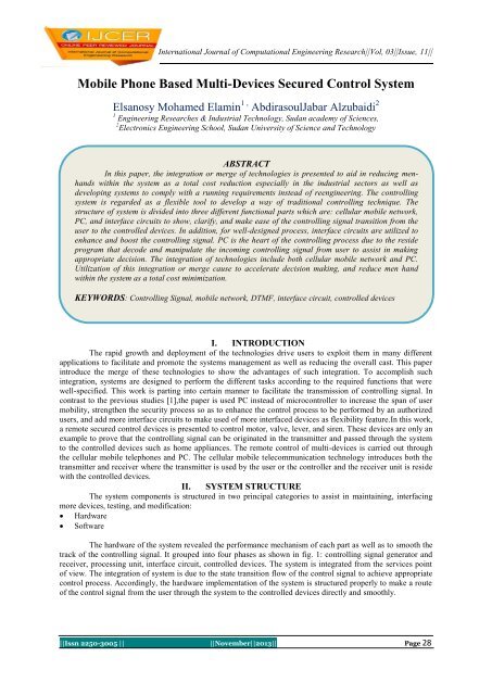
ABSTRACT<br />
In this paper, the integration or merge of technologies is presented to aid in reducing menhands<br />
within the system as a total cost reduction especially in the industrial sectors as well as<br />
developing systems to comply with a running requirements instead of reengineering. The controlling<br />
system is regarded as a flexible tool to develop a way of traditional controlling technique. The<br />
structure of system is divided into three different functional parts which are: cellular mobile network,<br />
PC, and interface circuits to show, clarify, and make ease of the controlling signal transition from the<br />
user to the controlled devices. In addition, for well-designed process, interface circuits are utilized to<br />
enhance and boost the controlling signal. PC is the heart of the controlling process due to the reside<br />
program that decode and manipulate the incoming controlling signal from user to assist in making<br />
appropriate decision. The integration of technologies include both cellular mobile network and PC.<br />
Utilization of this integration or merge cause to accelerate decision making, and reduce men hand<br />
within the system as a total cost minimization.<br />
KEYWORDS: <strong>Control</strong>ling Signal, mobile network, DTMF, interface circuit, controlled devices<br />
I. INTRODUCTION<br />
The rapid growth and deployment of the technologies drive users to exploit them in many different<br />
applications to facilitate and promote the systems management as well as reducing the overall cast. This paper<br />
introduce the merge of these technologies to show the advantages of such integration. To accomplish such<br />
integration, systems are designed to perform the different tasks according to the required functions that were<br />
well-specified. This work is parting into certain manner to facilitate the transmission of controlling signal. In<br />
contrast to the previous studies [1],the paper is used PC instead of microcontroller to increase the span of user<br />
mobility, strengthen the security process so as to enhance the control process to be performed by an authorized<br />
users, and add more interface circuits to make used of more interfaced devices as flexibility feature.In this work,<br />
a remote secured control devices is presented to control motor, valve, lever, and siren. These devices are only an<br />
example to prove that the controlling signal can be originated in the transmitter and passed through the system<br />
to the controlled devices such as home appliances. The remote control of multi-devices is carried out through<br />
the cellular mobile telephones and PC. The cellular mobile telecommunication technology introduces both the<br />
transmitter and receiver where the transmitter is used by the user or the controller and the receiver unit is reside<br />
with the controlled devices.<br />
II. SYSTEM STRUCTURE<br />
The system components is structured in two principal categories to assist in maintaining, interfacing<br />
more devices, testing, and modification:<br />
Hardware<br />
Software<br />
The hardware of the system revealed the performance mechanism of each part as well as to smooth the<br />
track of the controlling signal. It grouped into four phases as shown in fig. 1: controlling signal generator and<br />
receiver, processing unit, interface circuit, controlled devices. The system is integrated from the services point<br />
of view. The integration of system is due to the state transition flow of the control signal to achieve appropriate<br />
control process. Accordingly, the hardware implementation of the system is structured properly to make a route<br />
of the control signal from the user through the system to the controlled devices directly and smoothly.<br />
||Issn 2250-3005 || ||November||2013|| Page 28
<strong>Mobile</strong> <strong>Phone</strong> <strong>Based</strong> <strong>Multi</strong>-<strong>Devices</strong>…<br />
III. HARDWARE<br />
1. The <strong>Control</strong>ling Signal<br />
The cellular mobile network represents the source of controlling signal that should be received by the<br />
controlled devices. It partially consists of the physical equipment, such as the radio transceiver, digital signal<br />
processors, and air interface as well as signaling scheme (dual tone multi-frequency, DTMF). The DTMF signal<br />
is the sum of two tones, one from a low group (697-941Hz) and one from a high group (1209-1477Hz) with<br />
each group containing four individual tones to allow for 12 unique combinations [10].<br />
2. MT8870 Receiver<br />
It is an integrated IC characterized with low power consumption, adjustable acquisition and release<br />
time, power down and inhibit mode, single 5v power supply, and dial tone suppression. It consists of band split<br />
filter and decoder functions with few external passive components to achieve design flexibility. External low<br />
cost 3.58 MHz color burst crystal is used to synchronize the information transmission and to provide a power<br />
down option which, when enabled, drops consumption to less than 0.5 mW[11].The DTMF receiver is defined<br />
generally into three functional stages. First, the interface stage, is carried out through (RC) passive components<br />
to block dc components control signal gain. Second, the integrated DTMF receiver itself where the transmitting<br />
system signals can be processed as state transition flow for each specific signal delivered through the interface<br />
stage. Third, the output control logic[5]:<br />
3. The Processing Unit<br />
The exploitation of computers in this work made most of the operational and maintenance aspects of<br />
the system easy, feasible, and flexible. The PC program software is well-interfaced with the user and controlled<br />
devices. The predefined process that aid in making an appropriate decision of the controlled devices is done in<br />
turbo C++ language for both easy concepts and applications.<br />
4. The Interface Circuits<br />
The interface circuits are used to boost signal transition in between different phases. Here, DB25 male<br />
connector, HD 74LS373, and ULN2803A are used. The DB-25 male connector is used for device control and<br />
communication through software program.It consist ofdata, control, and status lines to be used as input/output<br />
buses. these lines are connected to relevant registers as stated in table 2.[7].Toboost the signal level to drive the<br />
devices, the ULN2803A is used. The HD74LS373 is 8-bit register features totem-pole three-states output<br />
designed specifically for driving highly capacitive or relatively low-impedance loads. The ULN2803A is<br />
designed for general purpose applications with a current limit circuits. It consist of eight Darlington<br />
transistorswith common emitters and internal suppression diodes for inductive loads. Each Darlington features a<br />
peak load current rating of about 500mA and can resist at least 95V in the off state[9].<br />
Table 1: Parallelport address<br />
Register LPT1 LPT2<br />
Data register(base address0) 0x378 0x278<br />
Status register(base address+1) 0x379 0x279<br />
<strong>Control</strong> register(base address+2) 0x37a 0x27a<br />
5. The load<br />
The controlled devices can be any low current devices such as zener diode for TTL circuits, relays, solenoids,<br />
stepper motors, magnetic print hammers, multiplexed LED and incandescent displays, and heaters[7]. In this<br />
case: dc motor, valve, lever, and siren circuit are used.<br />
IV. The Design Concepts<br />
For more simplification, both fig. 1 and table 2 are clarifying the concepts of design and the flow of the<br />
logical control signal sequences in between the user and devices via a communication channel. To fulfill such<br />
process, two mobile phones are used to transmit and receive data according to the network requirements.<br />
||Issn 2250-3005 || ||November||2013|| Page 29
<strong>Mobile</strong> <strong>Phone</strong> <strong>Based</strong> <strong>Multi</strong>-<strong>Devices</strong>…<br />
M<br />
obi<br />
le1<br />
PC<br />
5v<br />
0.1 µ<br />
0.2<br />
F<br />
M<br />
obi<br />
le2<br />
0.1 µ F<br />
120 kΩ<br />
0 v<br />
120 kΩ<br />
200 kΩ<br />
1 IN+<br />
4 Vref<br />
7 OSC1<br />
DT<br />
MF<br />
8 OSC2<br />
Re<br />
2 IN- cei<br />
ver<br />
3 GS 88<br />
70<br />
17 St/GT<br />
16 EST<br />
9 Vss<br />
Vdd 18<br />
TOE 10<br />
INH 5<br />
StD 15<br />
Q3 13<br />
Q2 12<br />
Q1 11<br />
PDWN 6<br />
5v<br />
25<br />
DB 3<br />
Co<br />
nn 4<br />
ect<br />
or 5<br />
10<br />
6<br />
11<br />
7<br />
12<br />
8<br />
13<br />
9<br />
3<br />
D1<br />
4<br />
D2<br />
7<br />
D3<br />
8<br />
D4<br />
13<br />
D5<br />
14<br />
D6<br />
17<br />
D7<br />
18<br />
D8<br />
HD74373<br />
Q1 2<br />
Q2 5<br />
Q3 6<br />
Q49<br />
Q5 12<br />
Q6 15<br />
Q7 16<br />
Q8 19<br />
ULN2803<br />
1 18<br />
2 17<br />
3 16<br />
4 15<br />
5 14<br />
6 13<br />
7 12<br />
8 11<br />
<strong>Control</strong>led<br />
<strong>Devices</strong><br />
Motor<br />
Valve<br />
Lever<br />
Siren<br />
Figure 1 The pins configuration of mobile phone based multi-devices secured control system<br />
1. The Cellular <strong>Mobile</strong> Network<br />
In this circuit, the controlling signal is sent by the cellular mobile phone no.1 to the cellular mobile<br />
phone no.2 which is located together with the DTMF controller circuit[12],[2].Through this process, the mobile<br />
phone network performed all the security issues such as authentication, confidentiality, anonymity, and<br />
integrity[6],[3].The output of the cellular mobile phone no.2 is then directed via a coupling capacitor to the<br />
DTMF decoder circuit<br />
Table 2: Thepins configurations of the system structure components<br />
Keypad 8870 DB25 74373 2803 <strong>Control</strong>led<br />
out In out In out In out in out <strong>Devices</strong><br />
0 2 11 13 2 3 2 1 18 Motor<br />
1 3 12 12 3 4 5 2 17 Valve<br />
2 - 13 11 4 7 6 3 16 Lever<br />
3 - 14 10 5 8 9 4 15 Siren<br />
4 - - - 6 13 12 5 14 -<br />
5 - - - 7 14 15 6 13 -<br />
6 - - - 8 17 16 7 12 -<br />
7 - - - 9 18 19 8 11 -<br />
8 - - - - - - - - -<br />
9 - - - - - - - - -<br />
2. MT8870 DTMF Receiver<br />
In the first stage of the DTMF receiver, the incoming controlling signal that comes from far distant<br />
mobile station no.1 up to the mobile station no.2 represents the input conditions to the integrated MT8870<br />
DTMF receiver through the RC adjustable gain circuit to set the signal according to the application<br />
requirements. Such a function is done inside the MT8870 by the buffer circuit which is represented by<br />
operational amplifier providing a unity gain and buffer the other input components from incoming into the<br />
DTMF receiver circuit. Then, the buffer circuit followed by the band pass filter which is minimize the incoming<br />
signal bandwidth.<br />
||Issn 2250-3005 || ||November||2013|| Page 30
<strong>Mobile</strong> <strong>Phone</strong> <strong>Based</strong> <strong>Multi</strong>-<strong>Devices</strong>…<br />
This filter is succeeded by splitting circuit to feed high and low pass filters to drive a digital detect<br />
circuit through high gain comparators which are limiting the signal to prevent detection of unwanted low level<br />
signal. The digital detection circuit consist of digital counting technique to determine the frequencies of the<br />
incoming signal and to verify that the incoming signal components correspond to standard DTMF<br />
frequencies[11]. So, a valid DTMF signal decoded to yield the output combinations as Q 1 – to - Q 4 .[13].<br />
The scenario that the system has to carry out sequentially depends upon the controlling signal that sent<br />
from user. The controlling signal is a combination of just decimal numbers:<br />
The operating software has to first put all the controlled devices in an idle state when starting.<br />
The Turbo C++ received only the correct password and initialized the system<br />
Reading the received signal from the user through the mobile phone no.1 as an output of the MT8870<br />
DTMF at the relevant address of the parallel communication port.<br />
Reacting to the incoming signal as appropriate decision to drive specific device.<br />
Showing the device states as indicator of control process actions to reflect that the functions are performed<br />
in specific and well manner according to the codes.<br />
start<br />
Inport=0x379<br />
Outport=0x378<br />
Read password<br />
PW correct<br />
No<br />
Yes<br />
Outport=0x00<br />
Read input value<br />
Is input=0x10<br />
yes<br />
Outport=0x01<br />
No<br />
Is input=0x20<br />
yes<br />
Outport=0x02<br />
No<br />
Is input=0x40<br />
yes<br />
Outport=0x04<br />
No<br />
Is input=0x80<br />
yes<br />
Outport=0x08<br />
No<br />
End<br />
Figure 2the program flow chart<br />
||Issn 2250-3005 || ||November||2013|| Page 31
<strong>Mobile</strong> <strong>Phone</strong> <strong>Based</strong> <strong>Multi</strong>-<strong>Devices</strong>…<br />
V. RESULTS AND DISCUSSION<br />
The system is carried out perfectly according to the codes and resulted in good performance as stated<br />
before. But, there are several constrains that affect the operation of the system negatively. These constrains are<br />
due to the network performance which is affected by other uncontrollable parameters. These constrains are:<br />
<br />
<br />
The network diverge mostly due to the environmental conditions.<br />
Handoff process as the user moving to high densely populated area when in progress.<br />
The aforementioned constrains may tend to completely loss, block or drop the controlling signal.<br />
VI. CONCLUSION<br />
In this paper, the mobile phone based multi-devices secured control system is presented. The control<br />
process is carried out securely and easily via both cellular mobile phones and PC. The exploit of technologies<br />
due to their rapid deployment and low cost, help in facilitating the controlling way or techniques as well as<br />
introducing many different advantages over traditional techniques. So, the transition of controlling signal<br />
through both cellular mobile network and PC to the controlled devices serve as developing tool to the security<br />
feature and enhance documentation, mentainance, and interfacing more devices to the system. Generally, the<br />
integration of technologies in this work is regarded as a flexible platform to the development.<br />
REFERENCES<br />
[1] Das, C. K. ;Sanaullah M. ; Sarower, H. M. G.; Hassan, and M. M. (2008), Development of a cell phone based remote control<br />
system: an effective switching system for controlling home and office appliances, International Journal of Electrical and<br />
Computer Sciences IJECS Vol. 9 No. 10<br />
[2] Johnnes, A. (2006), Investigation issues in mobile network in security, Modern Applied Science, Vol.2 No. 6 (2:6)<br />
[3] Ja´afar, A. S.; Soufian, Y.; Mohamed, N. (2006), Analysis and enhancement of authentication algorithm in mobilenetworks<br />
[4] Khiyal, M. S.; Khan A. ; Shehzadi, E. (2008), SMS based wireless home appliance control system for automating appliances and<br />
security, Issues in Informing Science and Information Technology, Vol. 6<br />
[5] MITEL (1995), ISO-CMOS MT8870D/MT8870D-1 Integrated DTMF receiver, Datasheet.<br />
[6] Praphul C. (2005), Bulletproof wireless security, Elsevier Inc. (144:152)<br />
[7] Renesas Technology Corp. (2005), HD74LS373 Octal D-Type Transparent latches, Rev.2.11 (1:3)<br />
[8] Svein Y. W, (2003), Forsics and GSM mobile telephone system, International Journal of Digital Evidence, Spring 2003, Vol.2<br />
Issue 1 (1:4)<br />
[9] TEXAS Instruments Incorp. (2012), ULN2803A Darlington transistor Array. Datasheet.<br />
[10] Yuvus, E.; Hassan, H. B.; Serkan, I.; Duygu, K. (2007), Safe and secure PIC based remote control application for intelligent<br />
home, IJCSNS International Journal of Computer Science and Network Security, Vol.7 No. 5 (179:181)<br />
[11] ZarlinkSemicoductor Inc. (2001), Application of the 8870 integrated DTMF receiver, Datasheet.<br />
[12] Ali, I. G. (2006), Security in wireless cellular networks (1:6), www.cse.wustl.edu.celluular _security<br />
[13] Clare Inc. (2001), M-8870 DTMF Receiver, Datasheet.<br />
||Issn 2250-3005 || ||November||2013|| Page 32