SCREAMIN' EAGLE TWIN CAM 110 (1800 CC ... - Harley-Davidson
SCREAMIN' EAGLE TWIN CAM 110 (1800 CC ... - Harley-Davidson
SCREAMIN' EAGLE TWIN CAM 110 (1800 CC ... - Harley-Davidson

You also want an ePaper? Increase the reach of your titles
YUMPU automatically turns print PDFs into web optimized ePapers that Google loves.
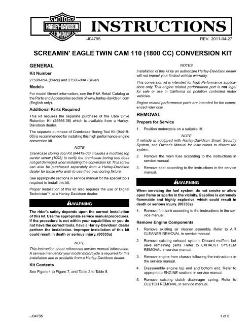
-J04795 REV. 2011-04-27<br />
<strong>SCREAMIN'</strong> <strong>EAGLE</strong> <strong>TWIN</strong> <strong>CAM</strong> <strong>110</strong> (<strong>1800</strong> <strong>CC</strong>) CONVERSION KIT<br />
GENERAL<br />
Kit Number<br />
27508-09A (Black) and 27506-09A (Silver)<br />
Models<br />
For model fitment information, see the P&A Retail Catalog or<br />
the Parts and Accessories section of www.harley-davidson.com<br />
(English only).<br />
Additional Parts Required<br />
This kit requires the separate purchase of the Cam Drive<br />
Retention Kit (25566-06) which is available from a <strong>Harley</strong>-<br />
<strong>Davidson</strong> dealer.<br />
The separate purchase of Crankcase Boring Tool Kit (94419-<br />
06) is recommended for installing this high performance engine<br />
conversion kit.<br />
NOTE<br />
Crankcase Boring Tool Kit (94419-06) includes a modified top<br />
center screw (1093) to verify the crankcase boring tool does<br />
not get damaged when installing the conversion kit.This screw<br />
can also be purchased separately from a <strong>Harley</strong>-<strong>Davidson</strong><br />
dealer for those who wish to use their own boring fixture.<br />
See appropriate sections in service manual for the special tools<br />
required to install this kit.<br />
Proper installation of this kit also requires the use of Digital<br />
Technician at a <strong>Harley</strong>-<strong>Davidson</strong> dealer.<br />
The rider's safety depends upon the correct installation<br />
of this kit. Use the appropriate service manual procedures.<br />
If the procedure is not within your capabilities or you do<br />
not have the correct tools, have a <strong>Harley</strong>-<strong>Davidson</strong> dealer<br />
perform the installation. Improper installation of this kit<br />
could result in death or serious injury. (00333a)<br />
NOTE<br />
This instruction sheet references service manual information.<br />
A service manual for your model motorcycle is required for this<br />
installation and is available from a <strong>Harley</strong>-<strong>Davidson</strong> dealer.<br />
Kit Contents<br />
See Figure 4 to Figure 7, and Table 2 to Table 5.<br />
NOTES<br />
Installation of this kit by an authorized <strong>Harley</strong>-<strong>Davidson</strong> dealer<br />
will not impact your limited vehicle warranty.<br />
This conversion kit is intended for High Performance applications<br />
only. This engine related performance part is not legal<br />
for sale or use in California on pollution controlled motor<br />
vehicles.<br />
Engine related performance parts are intended for the experienced<br />
rider only.<br />
REMOVAL<br />
Prepare for Service<br />
1. Position motorcycle on a suitable lift.<br />
NOTE<br />
If vehicle is equipped with <strong>Harley</strong>-<strong>Davidson</strong> Smart Security<br />
System, see Owner's Manual for instructions to disarm the<br />
system.<br />
2. Remove the main fuse according to the instructions in<br />
service manual.<br />
3. Remove seat according to the instructions in the service<br />
manual.<br />
When servicing the fuel system, do not smoke or allow<br />
open flame or sparks in the vicinity. Gasoline is extremely<br />
flammable and highly explosive, which could result in<br />
death or serious injury. (00330a)<br />
4. Remove fuel tank according to the instructions in the service<br />
manual.<br />
Remove Engine Components<br />
1. Remove existing air cleaner assembly. Refer to AIR<br />
CLEANER REMOVAL in service manual.<br />
2. Remove existing exhaust system. Discard mufflers but<br />
save remaining parts. Refer to EXHAUST SYSTEM<br />
REMOVAL in service manual.<br />
3. Remove engine from chassis following the instructions in<br />
the service manual.<br />
4. Disassemble engine top end and bottom end. Refer to<br />
appropriate ENGINE sections in service manual.<br />
5. Remove existing clutch diaphragm spring. Refer to<br />
CLUTCH REMOVAL in service manual.<br />
-J04795 1 of 8
MACHINE CRANKCASE<br />
is03517<br />
The procedures in this instruction sheet should be performed<br />
by one experienced in precision measuring techniques.<br />
Failure to meet tolerances called for in this<br />
instruction sheet can result in engine damage. (00511b)<br />
Crankcase Boring Preparation<br />
NOTE<br />
During final reassembly of the engine, <strong>Harley</strong>-<strong>Davidson</strong><br />
recommends replacing the Original Equipment cylinder studs<br />
with Screamin' Eagle High Tensile Studs (16505-01).<br />
1. Remove cylinder studs from the engine crankcase.<br />
2. Mask off all bearings and oil holes to prevent debris and<br />
contaminants from entering those areas.<br />
3. Inspect and clean engine case mating surfaces.<br />
4. See Figure 6. Reassemble engine case with original<br />
screws, except the top center screw between the cylinders,<br />
and tighten to specifications listed in service manual.<br />
NOTE<br />
To prevent damage to crankcase boring tool, it is important to<br />
replace the top center screw with a modified top center screw<br />
(1093). This screw is included in the Crankcase Boring Tool<br />
Kit (94419-06) and can be purchased separately from a <strong>Harley</strong>-<br />
<strong>Davidson</strong> dealer.<br />
5. Install modified top center screw (1093) between the cylinders<br />
and tighten to 50-90 in-lbs (5.6-10.2 Nm).<br />
NOTE<br />
To aid in crankcase boring, a Screamin' Eagle Crankcase<br />
Boring Tool Kit (94419-06) is available. Modified top center<br />
screw (1093) is included in this kit. Refer to <strong>Harley</strong>-<strong>Davidson</strong><br />
Genuine Motor Accessories and Genuine Motor Parts catalog<br />
or Screamin' Eagle Pro catalog.<br />
6. See Figure 1 and Table 1. Machine crankcase cylinder<br />
spigot bore and O-ring counter bore to the dimensions<br />
shown.<br />
1. O-ring counterbore<br />
2. Spigot bore<br />
1<br />
Figure 1. Spigot Bore and O-Ring Counterbore Dimensions<br />
Table 1. Spigot Bore and O-Ring Counterbore Dimensions<br />
Description<br />
Spigot Bore<br />
O-Ring Counterbore<br />
Modify Crankcase<br />
Bore<br />
2<br />
4.205 +/- 0.010 in.<br />
(107 +/- 0.25 mm)<br />
4.415 +/- 0.002 in.<br />
(112 +/- 0.05 mm)<br />
NOTE<br />
Depth<br />
1.625 +/- 0.010 in.<br />
(41.3 +/- 0.25 mm)<br />
0.085 +/- 0.003 in.<br />
(2.16 +/- 0.08 mm)<br />
To prevent severe engine damage, thoroughly clean and<br />
remove all chips and debris from the engine crankcase after<br />
boring.<br />
1. Disassemble crankcase and wash (or clean) chips and<br />
debris from engine crankcase halves as necessary.<br />
2. See Figure 3. Using a 11/32 in. (8.7 mm) drill bit, drill out<br />
the existing threads of the top center screw hole. Drill to<br />
a depth of 0.79 in. (20 mm) from the gasket surface.<br />
3. Using a size "F" in. (6.6 mm) drill bit, extend the top center<br />
screw hole 1.00 in. (25.4 mm) maximum to a depth of 1.79<br />
in. (45.5 mm) from the gasket surface.<br />
4. Using a bottoming tap (purchased separately) size 5/16-<br />
18 UNC-2B, tap the screw hole to a minimum depth of<br />
1.59 in. (40.4 mm) from the gasket surface.<br />
5. See Figure 2 and Figure 3. Remove the thin material<br />
between the cylinders next to the top center screw as<br />
shown, by using a 5/8 in. (16 mm) ball end mill and milling<br />
a 5/16 in. (16 mm) radius at the two points shown.<br />
-J04795 2 of 8
is03456<br />
6. Refer to the appropriate service manual and assemble<br />
the engine with the following changes:<br />
a. Tighten all of the engine crankcase screws to the<br />
specified torque, except the top center engine crankcase<br />
screw.<br />
b. See Figure 6. After the cylinders and heads have<br />
been installed and the hardware tightened to specification,<br />
install the top center engine crankcase screw<br />
(15) supplied in kit. Tighten screw to 50-90 in-lbs<br />
(5.6-10.2 Nm).<br />
Figure 2. Cylinder Wall<br />
is03502<br />
2 3 4<br />
10<br />
10<br />
1<br />
5<br />
6 7<br />
8 9<br />
1. Tap hole with a 5/16-18 UNC-2B bottoming tap 6. Extend hole depth - 1.00 in. (25.4 mm) maximum<br />
2. Extended full thread depth - 0.80 in. (20 mm)<br />
7. Unthreaded screw hole depth - 0.79 in. (20 mm)<br />
3. Distance - 0.48 in. (12 mm)<br />
8. Distance to center of crank - 5.90 in. (150 mm)<br />
4. Distance - 0.48 in. (12 mm)<br />
9. Distance to center of crank - 6.00 in. (152 mm)<br />
5. Drilled hole diameter - 0.34 in. (8.6 mm)<br />
10. Radius - 0.31 in. (7.94 mm) - use 5/8 in. (16 mm)<br />
ball end mill<br />
Figure 3. Top Center Engine Crankcase Screw Hole Modification<br />
INSTALLATION<br />
Install Engine and Clutch Components<br />
1. See Figure 6. Inspect camshaft needle bearings (7) and<br />
replace if necessary.<br />
2. See Figure 4 through Figure 6. Assemble engine top end<br />
and bottom end using parts from kit. Refer to appropriate<br />
ENGINE sections in service manual.<br />
3. Install engine in chassis following the instructions in the<br />
service manual.<br />
4. Install clutch diaphragm spring from kit. Refer to CLUTCH<br />
INSTALLATION in service manual.<br />
5. See Figure 7. Install exhaust system using mufflers (1)<br />
from kit. Refer to EXHAUST SYSTEM INSTALLATION in<br />
service manual.<br />
6. See Figure 4. Install Air Cleaner Kit (29592-05) following<br />
the instructions in the Instruction Sheet.<br />
Install ACR Overlay Wire Harness<br />
See Figure 7. Install ACR Overlay Wire Harness Kit (70623-<br />
06) following the instructions in the Instruction Sheet.<br />
Final Assembly<br />
1. Install seat according to the instructions in the service<br />
manual.<br />
-J04795 3 of 8
After installing seat, pull upward on seat to be sure it is<br />
locked in position. While riding, a loose seat can shift<br />
causing loss of control, which could result in death or<br />
serious injury. (00070b)<br />
2. Install fuel tank according to the instructions in the service<br />
manual.<br />
3. Install main fuse according to the instructions in service<br />
manual.<br />
You must recalibrate the ECM when installing this kit.<br />
Failure to properly recalibrate the ECM can result in severe<br />
engine damage. (00399b)<br />
4. Download the new ECM calibration using the Digital<br />
Technician at a <strong>Harley</strong>-<strong>Davidson</strong> dealer.<br />
5. Start and run engine. Repeat several times to verify proper<br />
operation.<br />
Operation<br />
Refer to BREAK-IN RIDING RULES in the Owner's Manual for<br />
instructions to break-in the motorcycle.<br />
-J04795 4 of 8
SERVICE PARTS<br />
is04669b<br />
10<br />
8<br />
9<br />
6<br />
3<br />
1<br />
5<br />
5<br />
4<br />
2<br />
7<br />
Figure 4. Service Parts: Screamin' Eagle Twin Cam <strong>110</strong> (<strong>1800</strong> cc) Conversion Kit<br />
Table 2. Service Parts: Screamin' Eagle Twin Cam <strong>110</strong> (<strong>1800</strong> <strong>CC</strong>) Conversion Kit<br />
Item<br />
Description (Quantity)<br />
Part Number<br />
Item<br />
Description (Quantity)<br />
Part Number<br />
1<br />
Cylinder assembly (Black) (2)<br />
17285-07A<br />
8<br />
Cylinder head, front, w\ACR, (black)<br />
17251-07B<br />
Cylinder assembly (Silver) (2)<br />
16815-07A<br />
Cylinder head, front, w\ACR, (silver)<br />
17261-07B<br />
2<br />
Piston (2)<br />
Not Sold Separately<br />
9<br />
Cylinder head, rear, w\ACR, (black)<br />
17252-07A<br />
3<br />
Piston Ring Set (2)<br />
21951-11<br />
Cylinder head, rear, w/ACR, (silver)<br />
17262-07A<br />
4<br />
Piston pin (2)<br />
22269-07<br />
10<br />
Automatic Compression Release<br />
(ACR)<br />
28861-07A<br />
5<br />
Piston pin circlip (4)<br />
22097-99<br />
11<br />
Air Cleaner Kit (Not Shown)<br />
29592-05<br />
6<br />
Gasket, cylinder head (2)<br />
16801-07C<br />
Notes: Piston Kit (21991-11) includes 2 through 5. Item 5 is also<br />
included in Engine Overhaul Gasket Kit (17350-07B). Refer to<br />
2009 FXSTSSE3 Parts Catalog (99458-09) for cylinder head<br />
assembly (8, 9) components.<br />
7<br />
O-ring, cylinder spigot (2)<br />
Not Sold Separately<br />
-J04795 5 of 8
is03589c<br />
2<br />
6<br />
8<br />
10<br />
9<br />
4<br />
13<br />
7<br />
5<br />
3<br />
1<br />
Figure 5. Service Parts: Screamin' Eagle Twin Cam <strong>110</strong> (<strong>1800</strong> cc) Conversion Kit<br />
Table 3. Service Parts: Screamin' Eagle Twin Cam <strong>110</strong> (<strong>1800</strong> <strong>CC</strong>) Conversion Kit<br />
Item<br />
1<br />
2<br />
3<br />
4<br />
5<br />
6<br />
7<br />
8<br />
Description (Quantity)<br />
Gasket, rocker cover base (2)<br />
Gasket, rocker cover top (2)<br />
Gasket, tappet cover (2)<br />
O-ring, middle push rod cover (4)<br />
O-ring, lower push rod cover (4)<br />
O-ring, upper push rod cover (4)<br />
O-ring, rocker arm support (2)<br />
Bolt 1/4-20 x 1-11/16 hex head<br />
w/Scotch grip (4)<br />
Part Number<br />
16719-99B<br />
17386-99A<br />
18635-99B<br />
11132A<br />
11145A<br />
11293<br />
11270<br />
4400<br />
Item<br />
9<br />
10<br />
11<br />
12<br />
Description (Quantity)<br />
Breather assembly (2)<br />
Baffle assembly (2)<br />
Seal, EFI intake (2) (not shown)<br />
Spring clutch diaphragm (not<br />
shown)<br />
Part Number<br />
17025-03A<br />
26500002<br />
26995-86B<br />
37951-86B<br />
Items 1 through 11 are included in Engine Overhaul Gasket<br />
Kit (17350-07B).<br />
-J04795 6 of 8
is03590b<br />
15<br />
13<br />
11<br />
9<br />
14<br />
21<br />
22<br />
6<br />
7<br />
10<br />
20<br />
12 22<br />
22<br />
8<br />
7<br />
16<br />
5<br />
3<br />
2<br />
4<br />
3<br />
1<br />
Figure 6. Service Parts: Screamin' Eagle Pro Twin Cam <strong>110</strong> (<strong>1800</strong> cc) Conversion Kit<br />
Table 4. Service Parts: Screamin' Eagle Twin Cam <strong>110</strong> (<strong>1800</strong> <strong>CC</strong>) Conversion Kit<br />
Item<br />
1<br />
2<br />
3<br />
4<br />
5<br />
6<br />
7<br />
8<br />
9<br />
10<br />
11<br />
Description (Quantity)<br />
Gasket, cam cover<br />
Washer<br />
Cam drive sprocket retention kit w/6294, screws and washers<br />
Retaining ring<br />
Camshaft, front<br />
Camshaft, rear<br />
Bearing, needle (2) (must be purchased separately, if needed)<br />
O-ring, oil pump to cam plate<br />
O-ring, cam plate to crankcase (2)<br />
O-ring, crankcase ring dowel (2)<br />
O-ring, piston cooling (2)<br />
Part Number<br />
25244-99A<br />
6294<br />
25566-06<br />
11461<br />
Not Sold Separately<br />
Not Sold Separately<br />
9215<br />
11293<br />
11301<br />
26432-76A<br />
11140<br />
-J04795 7 of 8
Item<br />
12<br />
13<br />
14<br />
15<br />
16<br />
17<br />
18<br />
19<br />
20<br />
21<br />
22<br />
23<br />
Retaining ring, internal<br />
O-ring, crankcase dowel (2)<br />
Seal, main bearing oil<br />
Table 4. Service Parts: Screamin' Eagle Twin Cam <strong>110</strong> (<strong>1800</strong> <strong>CC</strong>) Conversion Kit<br />
Screw, top center crankcase, long<br />
O-ring, CPS (not shown)<br />
Seal, exhaust (2) (not shown)<br />
Description (Quantity)<br />
Seal, oil interconnect (not shown) (Softail models only)<br />
Valve seal (4) (not shown) (not required)<br />
Main bearing<br />
Thrust washer<br />
Bearing kit, w/ 8972, 24605-07, 35114-02 + inner race (not shown)<br />
Screw, modified, crankcase boring (not shown) (must be purchased separately)<br />
35114-02<br />
Part Number<br />
Not Sold Separately<br />
12068<br />
1090A<br />
11289A<br />
65324-83B<br />
45359-00<br />
18067-09<br />
24605-07<br />
8972<br />
24004-03B<br />
Notes:<br />
Items 5 and 6 are available in Cam Kit (25638-07)<br />
Items 8 through 22 are included in Engine Overhaul Gasket Kit (17350-07B)<br />
Items 13 and 7 (table 2) are available in Seal Kit (11907) which is included in the Engine Overhaul Gasket Kit<br />
1093<br />
is03619b<br />
1<br />
1<br />
2<br />
Figure 7. Service Parts: Screamin' Eagle Twin Cam (<strong>1800</strong> <strong>CC</strong>) Conversion Kit<br />
Table 5. Service Parts: Screamin' Eagle Twin Cam <strong>110</strong> (<strong>1800</strong> <strong>CC</strong>) Conversion Kit<br />
Item<br />
1<br />
2<br />
Muffler, catalytic (2)<br />
Description (Quantity)<br />
ACR Overlay Wire Harness Kit (Refer to Instruction Sheet J04210)<br />
65872-09<br />
70623-06<br />
Part Number<br />
-J04795 8 of 8