for Wheel Loaders - HydraForce
for Wheel Loaders - HydraForce
for Wheel Loaders - HydraForce

Create successful ePaper yourself
Turn your PDF publications into a flip-book with our unique Google optimized e-Paper software.
Main headquarters, engineering<br />
and manufacturing facility in<br />
Lincolnshire Illinois,<br />
just north of Chicago.<br />
European headquarters,<br />
engineering and manufacturing facility<br />
in Birmingham, England.<br />
Precision machining facility<br />
in Lincolnshire, Illinois.<br />
Asian/Pacific headquarters,<br />
precision machining and manifold assembly facility<br />
in Changzhou, China, near Shanghai.<br />
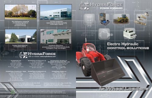
Electro Hydraulic<br />
CONTROL SOLUTIONS<br />
Visit our website: www.hydra<strong>for</strong>ce.com<br />
HYDRAFORCE INC<br />
500 Barclay Blvd.<br />
Lincolnshire, IL 60069<br />
Phone: 847 793 2300<br />
Fax: 847 793 0086<br />
Member: National Fluid Power Assoc.<br />
ISO 9001<br />
HYDRAFORCE HYDRAULICS – INDIA<br />
Vatika Business Centre<br />
Suite No. 22, Level 5, C Wing<br />
Techpark One, Airport Road<br />
Yerwada, Pune 411006<br />
Maharashtra, India<br />
Tel: +91 020 40111304<br />
Fax: +91 020 40111105<br />
Email: bharatb@hydra<strong>for</strong>ce.com<br />
HYDRAFORCE HYDRAULICS LTD<br />
St. Stephens Street<br />
Birmingham B6 4RG England<br />
Phone: 0121 333 1800<br />
Fax: 0121 333 1810<br />
Member: British Fluid Power Assoc.<br />
ISO 9001 & ISO 14001<br />
HYDRAFORCE HYDRAULICS LTD<br />
Prager Ring 4-12<br />
D-66482 Zweibrücken, Germany<br />
Tel: +49 (0) 6332 79 2350<br />
Mobile: +49 (0) 162 200 1553<br />
Fax: +49 (0) 6332 79 2359<br />
Email: markusb@hydra<strong>for</strong>ce.com<br />
HYDRAFORCE HYDRAULIC<br />
SYSTEMS (CHANGZHOU) CO., LTD<br />
388 W. Huanghe Road, Building 15A<br />
GDH Changzhou Airport Indl Park<br />
Xinbei District<br />
Changzhou, China 213022<br />
Phone: +86 519 6988 1200<br />
ISO 9001<br />
HYDRAFORCE KOREA LLC<br />
#306, Mirim Plaza<br />
1132-1, Jungdong, Wonmigu,<br />
Bucheon, Kyunggido, Korea<br />
Tel: +82 32 328 2170<br />
Fax: +82 32 328 2172<br />
Email: jong-seongl@hydra<strong>for</strong>ce.com<br />
<strong>HydraForce</strong>, Inc. (USA): DUNS #13-120-1493; FSCM<br />
#005K6 Fed. Tax #36-3555856 ISO 9001<br />
Registered Member of National Fluid Power Association<br />
<strong>HydraForce</strong> Hydraulics Ltd. (U.K.): Reg. in Cardiff.; Reg.<br />
No. 2286591 ISO 9001 and ISO 14001<br />
Registered Member of British Fluid Power Association<br />
<strong>HydraForce</strong> valves meet RoHS environmental requirements restricting the use of cadmium, quick silver, lead hexavalent chrome,<br />
polybrominated biphenyl (PPB) or polybrominated diphenyl ester (PPDE) in products, components and packing materials.<br />
All <strong>HydraForce</strong> products meet requirements limiting the use of hazardous materials as indentified in OSHA Standard 1910.1200(g).<br />
<strong>for</strong> <strong>Wheel</strong> <strong>Loaders</strong><br />
© Copyright 2012 <strong>HydraForce</strong>, Inc. All rights reserved. <strong>HydraForce</strong> and the <strong>HydraForce</strong> logo are registered trademarks of <strong>HydraForce</strong>, Inc.
TABLE OF CONTENTS<br />
Load-Handling -<br />
Load-Sense EH Boost, Park<br />
Brake, Grapple, Tool Carrier and<br />
Attachment..............Pages 10-11<br />
• Increased functionality<br />
• Wide range of adaptable<br />
solutions <strong>for</strong> precise control<br />
• Low leakage load-holding<br />
• Stand-alone or custom<br />
manifold designs<br />
• Flow capabilities up to<br />
380 lpm/100 gpm<br />
Boom Suspension -<br />
Boom Suspension,<br />
Accumulator Charging..........Pages 6-7<br />
• Com<strong>for</strong>t<br />
• Vibration control<br />
• Improved safety<br />
<strong>HydraForce</strong> hydraulic controls can enhance the capability<br />
of any wheel loader – from the compact 80 horsepower<br />
models, through the mid-range 80 to 200 HP models, up to<br />
the powerful 250 HP and above machines.<br />
With our comprehensive line of cartridge valves, manifolds,<br />
and high per<strong>for</strong>mance electronic controls, <strong>HydraForce</strong><br />
can provide numerous custom control solutions <strong>for</strong> wheel<br />
loaders. This brochure shows some easy ways to apply<br />
electro-hydraulics on wheel loaders to minimize vibration,<br />
improve load-handling per<strong>for</strong>mance, increase efficiency,<br />
reduce fuel consumption, optimize operator com<strong>for</strong>t, and<br />
ensure machine safety.<br />
Powertrain - Transmission,<br />
Cooling, Clutch........Pages 4-5<br />
• Clutch engage/disengage<br />
• Accurate clutch pressure control<br />
• 10,000,000 cycle life testing<br />
• 1,000 hours salt spray rating<br />
• IP69K waterproof coil<br />
Main Controls -<br />
Bucket, Brakes, Steering and Emergency<br />
Steering......................Pages 8-9<br />
• Low leakage load holding<br />
• Dual accumulator charging<br />
• Meter in/meter out functionality<br />
• Bridge circuit technology<br />
Electronic Controls.........Page 13<br />
• Rugged & reliable<br />
• Hardware & software<br />
• CoDeSys programming<br />
• Flexible configurations<br />
The <strong>HydraForce</strong><br />
Difference...........Page 12<br />
• Highest quality guaranteed<br />
• Speed to market<br />
• Flexible and responsive<br />
• Over 600 combined years of<br />
cartridge development experience<br />
• Leading edge technology<br />
2 3
POWERTRAIN<br />
Transmission<br />
PTO Control<br />
Cooling<br />
Clutch<br />
Transmission and PTO Solutions<br />
The circuit shown has a nominal flow rate of<br />
114 lpm/30 gpm with a main system relief<br />
valve.<br />
Torque Converter<br />
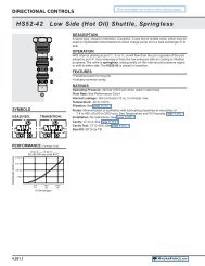
SV98-T39<br />
TS98-T34<br />
Lubrication<br />
TS98-T34<br />
EP12-S35<br />
EP12-S35<br />
Optimize wheel loader powertrain systems<br />
with hydraulic cartridge valves and<br />
manifolds with programmable controllers.<br />
Synchronize control of transmission clutch, PTO,<br />
and engine speed with the <strong>HydraForce</strong> CoreTek<br />
controller. Its programming software is available<br />
as a free download from the <strong>HydraForce</strong> web<br />
site. The CoreTek controller (circuit at right)<br />
can synchronize proportional valves, such as the<br />
TS98-34, to regulate <strong>for</strong>ward, reverse and multiple<br />
clutch actuation with smooth and accurate control<br />
of pressure. Clutch fill characteristics can be<br />
custom-programmed. PTO control can be accomplished<br />
with the EHPR98-T38 proportional valve.<br />
Clutch Engagement Per<strong>for</strong>mance (TS98-T34)<br />
Cooler<br />
SV98-T39<br />
SV98-T39<br />
TS98-T34<br />
TS98-T34 TS98-T34 EHPR98-T38<br />
Quiet down that fan drive. . .<br />
EHPR98-T38 Valve<br />
<strong>for</strong> PTO Control<br />
Park Brake<br />
Diff Lock<br />
4WD<br />
Fwd Clutch<br />
Rev Clutch<br />
1st Clutch<br />
2nd Clutch<br />
Fan Drive Solution<br />
3rd Clutch<br />
PTO Clutch<br />
• Clutch engage / disengage, Power Shift<br />
• Accurate clutch pressure control<br />
• Main system pressure regulation<br />
• Diff. Lock engage / disengage<br />
• PTO control<br />
SV08-30<br />
CV12-20<br />
T<br />
A<br />
Fan drives controlled by hydraulic cartridge<br />
valves are quieter and run on less horsepower<br />
than mechanical fan drives, providing greater fuel<br />
economy <strong>for</strong> wheel loaders.<br />
Control valves with multiple temperature inputs<br />
can be used to provide variable fan speed control<br />
depending on air temperature, load, and cooling<br />
requirements. If the radiator gets clogged, twoposition,<br />
four-way solenoid valves can automatically<br />
reverse fan direction.<br />
Electronic control of the hydraulic cooling system<br />
can be achieved using either an EFDR programmable<br />
valve driver or a CoreTek controller<br />
(ECU).<br />
Fan Output Per<strong>for</strong>mance<br />
TO<br />
ECM<br />
CoreTek<br />
Model<br />
ECU-0710<br />
CAN HI<br />
CAN LOW<br />
Plug-In<br />
Mount<br />
on<br />
Forward<br />
Valve<br />
Operator Input<br />
4<br />
3<br />
2<br />
1<br />
TS98-T34<br />
Valves <strong>for</strong><br />
Clutch<br />
Control<br />
Reverse<br />
Forward<br />
RV10-22<br />
4<br />
TS10-27<br />
Fan<br />
3<br />
2<br />
TS10-27 Valve<br />
<strong>for</strong> Fan Control<br />
1<br />
• Solutions available <strong>for</strong> flows up to<br />
190 lpm (50 gpm)<br />
• Fail safe high or low<br />
• Lubrication pressure control<br />
• Preconfigured controls available<br />
• Reduce horsepower consumption<br />
PD16-S60N<br />
CV12-20<br />
RV10-22<br />
B<br />
4 5
BOOM SUSPENSION<br />
Boom Suspension<br />
Accumulator Charging<br />
Boom Suspension Solutions<br />
Figure 1: Without Boom Suspension<br />
Ride control solutions fall into two categories: Passive or Active.<br />
<strong>HydraForce</strong> suspension systems improve load-handling per<strong>for</strong>mance<br />
<strong>for</strong> wheel loaders and also enhance operator com<strong>for</strong>t by<br />
reducing vibration and improving ride control. Optimal combinations<br />
of cartridge valves in customized manifolds that feature an integral<br />
accumulator allow <strong>for</strong> smooth suspension of the boom.<br />
How Boom Suspension Works<br />
In a wheel loader, the boom suspension basically functions as a<br />
shock absorber <strong>for</strong> the bucket, creating a smoother ride <strong>for</strong> the<br />
operator.<br />
Boom suspensions have the following benefits:<br />
• Improved wheel contact with the ground, which helps steering<br />
and stopping.<br />
• Load “floats” over terrain, allowing higher transport speed,<br />
fewer repairs and downtime and increased productivity.<br />
• Reduced vibration with loaded or unloaded bucket, fulfilling<br />
Vibration Directive 2002.44.EC and improving driver com<strong>for</strong>t.<br />
Figure 2: With Boom Suspension<br />
Passive Boom Suspension<br />
In a passive system, everything is<br />
pre-set – accumulator volume, precharge<br />
pressure and damping characteristics.<br />
Height control and spring rate are set<br />
according to load. The suspension can<br />
then be switched on or off. When on,<br />
damping is preset to a “best fit” constant.<br />
This solution features a dedicated<br />
PED rated relief valve <strong>for</strong> accumulator<br />
protection and low pressure drop/ high<br />
flow HyPer<strong>for</strong>mance logic elements<br />
<strong>for</strong> low damping pressure, and easy on/<br />
off pressure adjustment.<br />
ACC1<br />
PS1<br />
ORF2<br />
ORF4<br />
EP1<br />
A<br />
B<br />
EP2<br />
LS1<br />
ORF1<br />
RV1<br />
CV2<br />
ORF3<br />
SV1<br />
RV2<br />
Main Stack Valve<br />
PL1<br />
MA<br />
CV1<br />
PD1<br />
NV1<br />
Acc<br />
T<br />
B<br />
Active Boom Suspension<br />
Accumulator<br />
T<br />
RV1<br />
SP1<br />
In an active system, at least one parameter is<br />
variable and can be changed depending on<br />
conditions.<br />
RV58-20<br />
SV12-28<br />
SV3<br />
CV08-20<br />
PS10-41<br />
SV10-22<br />
PT2<br />
GAC<br />
ORF1<br />
CV1<br />
SV1<br />
SV3<br />
SV2<br />
GA<br />
A<br />
PT1<br />
Damping and spring rate can be adjusted in<br />
real time with a more sophisticated adaptive or<br />
active suspension system, which continuously<br />
adapts to the conditions of terrain, speed,<br />
etc. Fast, precise, repeatable valve response<br />
with low hysteresis is essential. <strong>HydraForce</strong><br />
can provide fully customizable programming<br />
algorithms and hydraulic controls <strong>for</strong> a broad<br />
range of boom suspension solutions.<br />
T<br />
P<br />
Example: Basic Boom Suspension<br />
This manifold consists of solenoid valves SV12-28,<br />
SV10-22, pilot-operated relief valve with a reverse flow<br />
check and RV58-20A, a sequence valve with external<br />
pilot and drain with integral sensing PS10-41A and a<br />
check valve CV08-20.<br />
ORF2<br />
AC2<br />
ACC2<br />
AC1<br />
ACC1<br />
Main Stack Valve<br />
6 7
MAIN CONTROLS<br />
Bucket<br />
Brakes<br />
Steering<br />
Emergency Steering<br />
<strong>HydraForce</strong> offers valves that are well-suited<br />
to the unique needs of Dynamic Accumulator<br />
Charging Circuits which are commonly<br />
used in conjunction with steering and braking<br />
units. Hydraulic braking systems are common<br />
on wheel loaders and towable implements.<br />
These circuits require a delicate balance<br />
between the priority flow steering and braking<br />
sections of the application, while simultaneously<br />
allowing excess flow to be diverted to<br />
tank or various auxiliary functions.<br />
A typical circuit provides priority flow <strong>for</strong><br />
the steering orbital while maintaining a<br />
predetermined range of pressure in the<br />
accumulator(s), to ensure adequate supply of<br />
oil <strong>for</strong> up to 7 brake depressions in the case<br />
of power loss. If one accumulator fails, the<br />
LS10-41 will shift over to protect the operational<br />
one. The ECxx-42 provides priority flow<br />
in required amount while allowing excess flow<br />
to be used <strong>for</strong> auxiliary functions.<br />
Primary Functions<br />
Primary Functions are the basic / standard control circuits, such<br />
as Steering and Braking.<br />
Steering / Braking<br />
These functions have priority over all other hydraulic demands.<br />
<strong>HydraForce</strong> manufacture a range of priority on demand pressure<br />
compensators with dynamic load sensing <strong>for</strong> fast response. With<br />
7 different models of priority on demand pressure compensator<br />
valves (ECxx-43), the rated flow capacities range from 34 lpm to<br />
530 lpm (9 gpm to 140 gpm).<br />
Dual Accumulator Charging<br />
<strong>HydraForce</strong> inverted shuttle valve LS10-41 provides<br />
additional safety when using dual accumulators. In the event of<br />
one accumulator failing (i.e. a ruptured bladder, etc.), the failed<br />
accumulator is isolated from the rest of the circuit, allowing the<br />
second accumulator to supply steering / braking.<br />
Primary Steering and Brake Solution<br />
BRAKES<br />
PRE-CHARGE<br />
BRAKES<br />
DYNAMIC<br />
STEERING<br />
Directional Bridge<br />
Load-holding bridge circuits<br />
provide the advantage of<br />
independent meter-in and<br />
meter-out timing with integral<br />
load sensing and pilot signaling,<br />
with minimal leakage.<br />
Circuit complexity, size and<br />
cost are minimized by<br />
using multi-function cartridge<br />
valves.<br />
Use a bridge circuit to give<br />
priority control <strong>for</strong> lift and<br />
lower functions on wheel<br />
loaders.<br />
Emergency Steering<br />
Emergency steering is used to enable steering in the<br />
event the engine dies or the brakes fail. The circuit below<br />
shows one-way hydraulic cartridge valves can be used in<br />
a load-sensing emergency steering circuit.<br />
P<br />
LS<br />
T<br />
Directional Bridge Circuit <strong>for</strong> Compact <strong>Wheel</strong> Loader<br />
SPCL16-40<br />
EC16-32<br />
A B A<br />
B<br />
CV04-20<br />
SPCL16-40<br />
RV08-20<br />
SPCL10-30<br />
EC10-32<br />
LS04-B30<br />
RV08-20<br />
CV04-20<br />
SPCL10-30<br />
EHPR series valves are designed to electrohydraulically<br />
pilot PE Series cartridge directional valves or other spooloperated<br />
controls. This cross-section shows the inner<br />
workings of a pilot-operated proportional valve (PE) and<br />
how it works with the EHPR valves in a circuit.<br />
P<br />
LS<br />
T<br />
LS10-41<br />
EMERGENCY STEER OUT<br />
PRIMARY STEER<br />
SENSOR<br />
CV08-20<br />
PE Series<br />
Directional Valve<br />
6<br />
5 4 3 2<br />
CV12-20<br />
Steering Flow<br />
CV1<br />
1<br />
Excess Flow<br />
to Auxiliary<br />
Functions<br />
EC16-42<br />
UP10-40<br />
RV08-20 Valve<br />
(Set higher than UP Valve)<br />
Load Sense<br />
EMERGENCY<br />
STEER PUMP<br />
RV10-20<br />
PD12-44<br />
PD1<br />
TANK<br />
EHPR<br />
System Drain<br />
Pump<br />
Separate Drain Line<br />
prevents back pressure<br />
on PE valve<br />
EHPR<br />
• Primary Flow to the brake section of<br />
the circuit<br />
• Auxiliary Flow diverted to the<br />
directional function<br />
LOAD SENSE<br />
8 9
LOAD-HANDLING<br />
Bucket<br />
Grapple<br />
Tool Carrier and Attachment<br />
Traction Control<br />
<strong>Wheel</strong> loaders are known <strong>for</strong> their versatility and today’s<br />
generation of machines can handle a great variety of<br />
auxiliary functions with an assortment of attachments,<br />
including grapples, <strong>for</strong>ks, and specialized buckets to<br />
handle loads from sand to snow.<br />
Load-handling and other auxiliary functions can be done<br />
with greater speed and power with the right hydraulic<br />
controls.<br />
Pilot Valves Guide the Flow<br />
Just as wheel loaders per<strong>for</strong>m a multitude of functions,<br />
<strong>HydraForce</strong> pilot valves guide a multitude of flows. These<br />
valves have an integral, waterproof solenoid coil.<br />
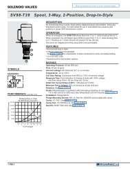
SV98-T39, T40<br />
For low pressure pilot systems or power shift transmission<br />
control, the SV98-T39 and SV98-T40 valves are an<br />
economical choice. The T39 is a three-way valve and the<br />
T40 is a four-way.<br />
EHPR98-T33, T35 and T38<br />
These proportional pressure control valves come in several<br />
sizes to control from 4 lpm (1.05 gpm) to 18 lpm (5 gpm)<br />
and two pressure ranges - 10.3 bar 1500 psi) or 241 bar<br />
(3500 psi). They are drop-in style, flange mounted, directacting,<br />
and can be infinitely adjusted using a variable<br />
electric input.<br />
TS98-T34<br />
For demanding applications with high flow, the TS98-T34<br />
pressure reducing valve can be used as a pressure limiting<br />
device. It’s a spool-type, drop-in proportional pressure<br />
reducing/relieving valve that can be infinitely adjusted.<br />
EH Reducing/ Relieving<br />
Proportional Control<br />
TS98-T34<br />
30 lpm/8 gpm<br />
30 bar/435 psi<br />
EHPR Reducing/ Relieving<br />
Proportional Control<br />
EHPR98-T33<br />
3.8 lpm/1 gpm<br />
241 bar/3500 psi<br />
Max. Reducing<br />
Pressure: 31 bar/450 psi<br />
EHPR98-T35<br />
5.7 lpm/1.5 gpm<br />
103 bar/1500 psi<br />
With the '-T35A' option,<br />
241 bar/3500 psi per<strong>for</strong>mance<br />
can be achieved.<br />
Max. Reducing<br />
Pressure: 20 bar/290 psi<br />
EHPR98-T38<br />
19 lpm/5 gpm<br />
241 bar/3500 psi<br />
Max. Reducing<br />
Pressure: 31 bar/450 psi<br />
Load Sense Boost<br />
Higher flows and shorter response times are<br />
possible with load sense boosting. When lower<br />
flows are adequate <strong>for</strong> the job, reduce standby<br />
pressures to save power.<br />
Load Sense Boost Circuit<br />
E-H BOOST<br />
LS - OUT<br />
EHPR08-33xx<br />
P<br />
LS SIGNALS IN<br />
A B C D<br />
LS10-50<br />
Pilot Selector<br />
Customize the speed of actuation with a Pilot Selector<br />
Circuit. Pilot valves can be used to control the pressure and<br />
flow of hydraulic fluid to a series of directional valves. In the<br />
circuit below, a vented spool-type logic element (EV) controls<br />
the pressure provided by an open center gear pump to a<br />
series of four solenoid valves (SV).<br />
Pilot Selector Circuit<br />
Tool Carrier and Attachment<br />
Hydraulic quick couplers allow wheel loaders the option to<br />
change attachments or tools. This Tool Carrier Attachment<br />
circuit has built-in load-sensing.<br />
Tool Carrier and Attachment Circuit<br />
P<br />
T<br />
LS - IN<br />
LS - OUT<br />
SP10-57C<br />
LS06-30<br />
Loader Park Brake Circuit<br />
A<br />
TANK<br />
SV12-21<br />
B<br />
SP10-57C<br />
C<br />
D<br />
SV10-28<br />
SUPPLY<br />
Solenoid Selector Valves<br />
SV98-T39 SV98-T39 SV98-T39 SV98-T39<br />
PARK BRAKE<br />
SV98-T39<br />
30 lpm/8 gpm<br />
45 bar/650 psi<br />
SV98-T40<br />
30 lpm/8 gpm<br />
45 bar/435 psi<br />
P-2T<br />
OPEN CENTER PUMP (GEAR)<br />
EV<br />
Tank<br />
Double blocking SV10-28 provides<br />
low leakage load holding to<br />
ensure park brake stays enabled.<br />
PARK BRAKE SENSOR<br />
10 11
VALVES AND ELECTRONIC CONTROLS<br />
SPCL16-40<br />
Proportional Directional Control,<br />
4-Port, Normally Closed with Check<br />
Isolated Load Sense<br />
HSPEC16-30<br />
Proportional Flow Control Valve with<br />
Integral Compensator<br />
Electronic Controls<br />
Model ECU-0710<br />
Up to 27 inputs, consisting of digital, pulse, current<br />
measuring feedback and analog. A total of seven<br />
output configurations can be set, including six PWM<br />
or digital high-side drivers and a single low-side<br />
driver.<br />
Model ECU-2415<br />
Up to 39 digital, pulse, current measuring feedback<br />
and analog inputs along with 24 outputs consisting of<br />
up to 24 PWM or digital high-side drivers.<br />
Flow: 152 lpm/40 gpm<br />
Pressure: 250 bar (3625 psi)<br />
SPCL16-32<br />
Solenoid-operated, 3-port,<br />
normally-closed, proportional,<br />
poppet type<br />
Flow: 132 lpm/35 gpm<br />
Pressure: 350 bar (5075 psi)<br />
RVCV56-20<br />
Relief, Directing Acting Poppet with<br />
Reverse Flow Check<br />
Model ECU-2032<br />
Up to 52 inputs and 20 outputs consisting of up to<br />
eight PWM or 20 digital high-side drivers.<br />
Model ECU-2820<br />
Up to 52 inputs and 28 outputs consisting of up to 24<br />
PWM or digital high-side drivers and up to four digital<br />
low-side drivers.<br />
Flow: 152 lpm/40 gpm<br />
Pressure: 250 bar (3625 psi)<br />
EHPR98-T3x<br />
Proportional, Reducing / Relieving,<br />
Drop-in<br />
1<br />
2<br />
Flow: 115 lpm/30 gpm<br />
Pressure: 420 bar (6100 psi)<br />
TSxx-27<br />
Proportional Pressure Control, Pilot-<br />
Operated Relief<br />
CORETEK PROGRAMMABLE<br />
MACHINE CONTROLLERS<br />
The new CoreTek line of general-purpose programmable<br />
controllers can be used as stand-alone<br />
controllers or integrated with other CAN networked<br />
devices. They are designed to withstand the environmental<br />
demands of mobile off-highway equipment<br />
applications. They feature flexible input and<br />
output configuration and are capable of driving up to<br />
3.0 amps per output pin.<br />
CoreTek controllers are fully sealed within a compact<br />
cast aluminum housing. Operating temperature<br />
range is -40° to +70°C (-40° to 158°F) and no external<br />
cooling or heat dissipation is required.<br />
SENSOR VALVES<br />
Select <strong>HydraForce</strong> valves can be<br />
ordered with an integral position<br />
sensing option capable of<br />
transmitting an on or off signal.<br />
This new sensing solution was<br />
designed <strong>for</strong> interchangeable use<br />
with existing <strong>HydraForce</strong> cartridge<br />
valves, is compatible with manual<br />
override options and uses an<br />
industry standard cavity.<br />
Flow: 18.9 lpm/5.0 gpm<br />
Pressure: 241 bar (3500 psi)<br />
Flow: up to 189 lpm/50 gpm<br />
Pressure: 241 bar (3500 psi)<br />
Our Breadth of Product<br />
As the largest manufacturer of hydraulic cartridge valves in the world, <strong>HydraForce</strong> offers an extensive range of solenoid,<br />
electro-proportional, directional, flow, and pressure control valves. In 2011, more than 200 new valves were introduced,<br />
including many high pressure and multi-function models. Cartridge valves <strong>for</strong> flow rates up to 379 lpm/100 gpm and<br />
operating pressures up to 350 bar/5,000 psi are sold individually, with housings or in manifold blocks. Valves can be<br />
custom-designed or standard product.<br />
<strong>HydraForce</strong> designs, manufactures and supports valve, manifold and accessory products supported by heavy duty<br />
electronic machine control capabilities.<br />
To request a free hydraulic integrated circuit (HIC) consultation, please visit:<br />
http://info.hydra<strong>for</strong>ce.com/Free-Custom-Circuit-Consultation/<br />
CoDeSys TM Programming<br />
CoDeSys or Controlled Development System is a<br />
complete development environment <strong>for</strong> Programmable<br />
Machine Controllers. The editors and debugging<br />
functions are based on the proven development<br />
program environments of advanced programming<br />
languages (such as Visual C++).<br />
CoDeSys software is available as a free download<br />
from <strong>HydraForce</strong>:<br />
http://www.hydra<strong>for</strong>ce.com/Electronics/<br />
CoDeSys software: Copyright © 3S - Smart Software Solutions GmbH<br />
HEAVY DUTY SENSORS<br />
<strong>HydraForce</strong> has accurate sensors designed <strong>for</strong> off-road applications.<br />
Our temperature sensors are thermistor style with padded resistors.<br />
ERT 120 – Output Signal: 5427.9 to 436.3 ohms<br />
Our pressure sensors have 1% total error band accuracy, are IP67 rated.<br />
ERP035 – <strong>for</strong> pressure ranges up to 35 bar (500 psi)<br />
ERP414 – <strong>for</strong> higher pressures up to 414 bar (6000 psi)<br />
12 13
OUR STORY<br />
Our Story<br />
The <strong>HydraForce</strong> story began in 1985 when the company<br />
was founded near Chicago by several partners who saw<br />
the mobile equipment industry’s need <strong>for</strong> quality hydraulic<br />
cartridge valves and manifolds delivered in a timely and<br />
responsive manner. They also saw the potential <strong>for</strong><br />
engineering innovation and design flexibility offered by<br />
cost-effective and space-saving cartridge valves and<br />
hydraulic integrated circuits.<br />
Since its founding, <strong>HydraForce</strong> continues to be a<br />
privately held company as it has grown to several<br />
manufacturing locations in North America, Europe and<br />
Asia, with a network of 120 stocking distributors who can<br />
offer local support across the globe.<br />
To maintain our core competency of speed to market,<br />
<strong>HydraForce</strong> has invested in application technical support<br />
tools including i-Design, our free hydraulic system design<br />
sofware, which integrates seamlessly with 3rd party<br />
simulation software, monthly webinars on new products<br />
and application tips, and an online product catalog.<br />
All <strong>HydraForce</strong> products carry a five-year limited<br />
warranty against defects in material and workmanship.<br />
<strong>HydraForce</strong> Vision Mission Statement<br />
To Be An Independent<br />
Provider Of Innovative<br />
Technical Solutions<br />
That Can Change The<br />
World<br />
To Provide Our Customers<br />
With The Highest Quality<br />
Hydraulic Valves And The<br />
Most Responsive Customer<br />
Support In The World<br />
Our Quality and Manufacturing Guarantee<br />
All three <strong>HydraForce</strong> plants in North America, Europe<br />
and Asia follow the same manufacturing processes and<br />
standards to ensure global consistency in product quality.<br />
• All products 100% tested<br />
• Use of Lean and Six Sigma practices<br />
• New product introduction tools such as:<br />
• Advanced Product Quality Planning (APQP)<br />
• Production Part Approval Process (PPAP)<br />
• Failure Mode and Effect Analysis (FMEA)<br />
• Statistical Process Control (SPC)<br />
• Continuous improvement through Kaizen<br />
• Responsive delivery with Kanban throughput system<br />
<strong>HydraForce</strong> Timeline<br />
1985<br />
<strong>HydraForce</strong> is created<br />
on principles of highest<br />
quality and customer<br />
response<br />
1988<br />
Achieved Ford Q1<br />
quality certification<br />
on first audit<br />
1991<br />
Achieved<br />
ISO 9001<br />
1993<br />
Achieved<br />
QS9000<br />
2006<br />
Received<br />
ISO 14001:2004<br />
2008<br />
Opened<br />
office in<br />
India<br />
2012<br />
To date, 13 patents<br />
have been awarded<br />
<strong>for</strong> innovative valve<br />
designs<br />
Received ISO 13849<br />
1985 1988 1990 1991 1995 2000 2005 2010 2011 2015 2020<br />
1989<br />
Opened<br />
European<br />
operation<br />
Worldwide Support<br />
1993<br />
Moved into<br />
Lincolnshire<br />
operation<br />
1997<br />
Expanded global<br />
headquarters<br />
by 50,000 sqft &<br />
opened Plant #2<br />
1999<br />
<strong>HydraForce</strong><br />
became #1 global<br />
manufacturer<br />
of cartridge valves<br />
2001<br />
Expanded global<br />
headquarters<br />
by 70,000 sqft &<br />
built new 50,000 sqft<br />
EU Operation<br />
2010<br />
Formalized 2015<br />
Strategic Plan &<br />
paid off all long<br />
term debt<br />
2011<br />
Opened 4th global<br />
mfg operation in<br />
China<br />
2005<br />
Opened offices<br />
in Korea, and<br />
China<br />
ISO 9001<br />
Continue<br />
global<br />
expansion<br />
MANUFACTURING<br />
TECHNICAL SALES<br />
DISTRIBUTION & SUPPORT<br />
14 15