Solar photovoltaic water pumping system using a new ... - Icrepq.com
Solar photovoltaic water pumping system using a new ... - Icrepq.com
Solar photovoltaic water pumping system using a new ... - Icrepq.com

Create successful ePaper yourself
Turn your PDF publications into a flip-book with our unique Google optimized e-Paper software.
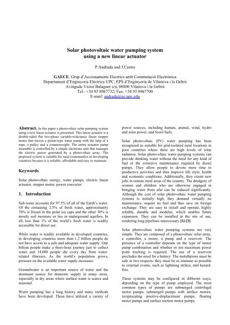
<strong>Solar</strong> <strong>photovoltaic</strong> <strong>water</strong> <strong>pumping</strong> <strong>system</strong><br />
<strong>using</strong> a <strong>new</strong> linear actuator<br />
P.Andrada and J.Castro<br />
GAECE, Grup d’Accionaments Electrics amb Commutació Electrònica<br />
Departament d’Enginyeria Elèctrica UPC, EPS d’Enginyeria de Vilanova i la Geltrú<br />
Avinguda Victor Balaguer s/n, 08800 Vilanova i la Geltrú<br />
Tel.: +34 93 8967732; Fax: +34 93 8967700<br />
E-mail: andrada@ee.upc.edu<br />
Abstract. In this paper a <strong>photovoltaic</strong> solar <strong>pumping</strong> <strong>system</strong><br />
<strong>using</strong> a <strong>new</strong> linear actuator is presented. This linear actuator is a<br />
double-sided flat two-phase variable-reluctance linear stepper<br />
motor that moves a piston-type <strong>water</strong> pump with the help of a<br />
rope, a pulley and a counterweight. The entire actuator pump<br />
ensemble is controlled by a simple electronic unit that manages<br />
the electric power generated by a <strong>photovoltaic</strong> array. The<br />
proposed <strong>system</strong> is suitable for rural <strong>com</strong>munities in developing<br />
countries because it is reliable, affordable and easy to maintain.<br />
Keywords<br />
<strong>Solar</strong> <strong>photovoltaic</strong> energy, <strong>water</strong> pumps, electric linear<br />
actuator, stepper motor, power converter.<br />
1. Introduction<br />
Salt <strong>water</strong> accounts for 97.5% of all of the Earth’s <strong>water</strong>.<br />
Of the remaining 2.5% of fresh <strong>water</strong>, approximately<br />
70% is frozen in the polar ice caps and the other 30% is<br />
mostly soil moisture or lies in underground aquifers. In<br />
all, less than 1% of the world’s fresh <strong>water</strong> is readily<br />
accessible for direct use.<br />
While <strong>water</strong> is readily available in developed countries,<br />
in developing countries more than 1.2 billion people do<br />
not have access to a safe and adequate <strong>water</strong> supply. One<br />
billion people make a three-hour journey just to collect<br />
<strong>water</strong> and 14,000 people die every day from <strong>water</strong>related<br />
illnesses. As the world’s population grows,<br />
pressure on the available <strong>water</strong> supply increases.<br />
Ground<strong>water</strong> is an important source of <strong>water</strong> and the<br />
dominant source for domestic supply in many areas,<br />
especially in dry areas where surface <strong>water</strong> is scarce and<br />
seasonal.<br />
Water <strong>pumping</strong> has a long history and many methods<br />
have been developed. These have utilized a variety of<br />
power sources, including human, animal, wind, hydro<br />
and solar power, and fossil fuels.<br />
<strong>Solar</strong> <strong>photovoltaic</strong> (PV) <strong>water</strong> <strong>pumping</strong> has been<br />
recognized as suitable for grid-isolated rural locations in<br />
poor countries where there are high levels of solar<br />
radiation. <strong>Solar</strong> <strong>photovoltaic</strong> <strong>water</strong> <strong>pumping</strong> <strong>system</strong>s can<br />
provide drinking <strong>water</strong> without the need for any kind of<br />
fuel or the extensive maintenance required by diesel<br />
pumps. They allow people to devote more time to<br />
productive activities and thus improve life style, health<br />
and economic conditions. Additionally, they create <strong>new</strong><br />
jobs in remote rural areas of the country. The drudgery of<br />
women and children who are otherwise engaged in<br />
bringing <strong>water</strong> from afar can be reduced significantly.<br />
Although the cost of solar <strong>photovoltaic</strong> <strong>water</strong> <strong>pumping</strong><br />
<strong>system</strong>s is initially high, they demand virtually no<br />
maintenance, require no fuel and thus save on foreign<br />
exchange. They are easy to install and operate, highly<br />
reliable, durable and modular, which enables future<br />
expansion. They can be installed at the site of use,<br />
rendering long pipelines unnecessary [1]-[3].<br />
<strong>Solar</strong> <strong>photovoltaic</strong> <strong>water</strong> <strong>pumping</strong> <strong>system</strong>s are very<br />
simple. They are <strong>com</strong>posed of a <strong>photovoltaic</strong> solar array,<br />
a controller, a motor, a pump and a reservoir. The<br />
presence of a controller depends on the type of motor<br />
pump <strong>com</strong>bination and whether or not maximum power<br />
point tracking is required. The use of a reservoir<br />
precludes the need for a battery. The installations must be<br />
safe in two respects: they must be as immune as possible<br />
to external events, such as lightning strikes, and hazardfree.<br />
These <strong>system</strong>s may be configured in different ways,<br />
depending on the type of pump employed. The most<br />
<strong>com</strong>mon types of pumps are submerged centrifugal<br />
motor pumps, submerged pumps with surface motors,<br />
reciprocating positive-displacement pumps, floating<br />
motor pumps and surface suction motor pumps.
Fig. 1. Proposed solar PV <strong>water</strong> <strong>pumping</strong> <strong>system</strong><br />
In developed countries, submerged centrifugal motor<br />
pumps, in which an induction three-phase squirrel cage<br />
motor is controlled by an inverter, are most <strong>com</strong>mon.<br />
However, solar <strong>photovoltaic</strong> <strong>pumping</strong> <strong>system</strong>s operating<br />
in rural <strong>com</strong>munities in developing countries must be<br />
cheap, reliable and maintainable by persons with limited<br />
formal education. Reductions in cost and gains in<br />
reliability can be obtained by reducing the <strong>com</strong>plexity of<br />
the controller and motor pump.<br />
In accordance with these arguments, in this paper we<br />
present a solar PV <strong>water</strong> <strong>pumping</strong> <strong>system</strong> <strong>using</strong> a <strong>new</strong><br />
linear actuator. A two-phase variable-reluctance linear<br />
stepper motor [6] moves a piston-type <strong>water</strong> pump and is<br />
controlled by a simple electronic unit. The proposed<br />
<strong>system</strong> is suitable for rural <strong>com</strong>munities in developing<br />
countries, because it is reliable, affordable and easy to<br />
maintain. To date, few authors have discussed <strong>system</strong>s of<br />
this type, although a design study of a fully submerged<br />
linear electromagnetic actuator has been proposed by<br />
T.D. Short and M.A. Mueller [4], whilst C. Perris and Z.<br />
Salameh [5] have presented a proposal that involved<br />
replacing a rotary motor and gearbox with a linear DC<br />
motor <strong>system</strong> controlled by a four-quadrant chopper,<br />
positioned at ground level and coupled to the pump via a<br />
long connecting rod.<br />
2. Description of the proposed solar PV<br />
<strong>water</strong> <strong>pumping</strong> <strong>system</strong><br />
A solar PV <strong>water</strong> <strong>pumping</strong> <strong>system</strong> suitable for rural<br />
<strong>com</strong>munities in developing countries is designed. The<br />
proposed <strong>system</strong> consists of a piston-type <strong>water</strong> pump, a<br />
two-phase variable-reluctance linear stepper motor [6]<br />
mounted onto the piston rod that drives the pump with the<br />
help of a rope, a pulley and a counterweight. The actuator<br />
pump ensemble is controlled by a simple electronic unit<br />
that manages the electric power generated by a<br />
<strong>photovoltaic</strong> array. The <strong>system</strong> is <strong>com</strong>pleted by a <strong>water</strong><br />
reservoir, as shown in Figure 1.<br />
A single-acting reciprocating positive-displacement<br />
piston or plunger pump was chosen, because this type of<br />
pump is highly suited to high head and low flow<br />
applications. Piston pumps <strong>com</strong>prise a cylinder with a<br />
reciprocating plunger inside it. The piston forces <strong>water</strong><br />
from the inlet side to the outlet side of the pump. In a<br />
single-acting pump the working cycle is <strong>com</strong>pleted with<br />
two strokes of the piston: a downward stroke and an<br />
upward stroke. The force required to pump the <strong>water</strong> can<br />
be estimated by<br />
F<br />
= d g γ A (N) (1)<br />
H H ef
where d is the density of <strong>water</strong>, g is the acceleration of<br />
gravity, γ is the leakage coefficient ( ≈ 0. 9 ), A is the<br />
piston surface and H ef is the effective height.<br />
The linear actuator allows the piston to move between its<br />
extreme positions at constant speed. A variablereluctance<br />
linear stepper motor is proposed because it can<br />
operate as an open loop <strong>system</strong>, it is mechanically robust,<br />
its control is straightforward and it can be manufactured<br />
in developing countries. The double-sided flat two-phase<br />
variable-reluctance linear stepper motor (Figure 2) was<br />
selected because of its simplicity and because, ideally, no<br />
net normal force is exerted on the mover.<br />
Fig. 3. Unipolar power converter<br />
Each phase must be turned on at around the point at<br />
d L<br />
which its own inductance increases, > 0 . Thus, a<br />
d x<br />
device such as a logic sequencer that is able to<br />
consistently send the right <strong>com</strong>mutation signals to the<br />
gates of the power switches is required (Figure 4).<br />
Fig. 2. Longitudinal cross-section of the linear actuator<br />
Because of the salient nature of both the stator and mover<br />
poles, the inductance of each phase varies with the<br />
mover’s position. The operating principle of the linear<br />
actuator is based on the minimum reluctance rule. Thus<br />
the thrust, if saturation is disregarded, takes the form:<br />
F<br />
ac<br />
1 2 d L<br />
= i (N) (2)<br />
2 d x<br />
The motor has four air gaps per phase. The stator pole<br />
width and the mover pole width are equal and are half the<br />
stator slot width. Therefore, its average thrust is<br />
determined by the following equation:<br />
F<br />
ac<br />
⎛ λna<br />
2<br />
4 ( B ) K v 1<br />
⎟ ⎞<br />
= δ Δ ⎜<br />
− bs<br />
w (N) (3)<br />
⎝ λa<br />
⎠<br />
where B δ is the flux density in the air gap, Δ is the current<br />
density, K V is the slot fill factor, λ na is the permeance per<br />
unit of length in the unaligned position, λ a is the<br />
permeance per unit of length in the aligned position, b s is<br />
the stator pole width and w is the normal length.<br />
The displacement of the mover equals the downward and<br />
upward strokes of the piston; therefore, a power converter<br />
must sequentially energize the phase windings of the<br />
motor and reverse the sequence each time the end<br />
positions of the mover are reached. Because simplicity<br />
was one of our main goals, we chose a unipolar power<br />
converter with only one switch per phase and a<br />
freewheeling diode (Figure 3).<br />
Fig. 4. Variation of phase inductances and <strong>com</strong>mutation signals<br />
The linear actuator is coupled with the pump rod and is<br />
linked to a pulley and a counterweight. This solution<br />
reduces the size and cost of the linear actuator and the<br />
power required from the <strong>photovoltaic</strong> array. The<br />
counterweight equalizes load requirements during a<br />
<strong>com</strong>plete cycle, i.e. the force generated by the linear<br />
actuator when it is moving upwards must be almost equal
to the force generated when it is moving downwards.<br />
Therefore, the final thrust of the actuator is given by<br />
1<br />
F ac = F H (N) (4)<br />
2<br />
and the mass of the counterweight is<br />
1 ⎛ FH<br />
⎞<br />
M cb = ⎜ + Fr<br />
⎟ (kg), (5)<br />
g ⎝ 2 ⎠<br />
F r being the weight of the rod, piston and mover.<br />
The PV array is made <strong>using</strong> <strong>com</strong>mercial PV panels. The<br />
configuration and disposition of the PV array depends on<br />
its location and on the <strong>pumping</strong> specifications. Given that<br />
the PV array exhibits nonlinear current-voltage<br />
characteristics and its maximum power point varies with<br />
solar irradiation and temperature, it is usually necessary<br />
to employ a device that is able to provide the voltage and<br />
current required by the actuator at all times. Nevertheless,<br />
in this case the electrical variables of the actuator and the<br />
PV array outputs can be adapted by <strong>com</strong>bining the logic<br />
sequencer with a current control stage.<br />
Finally, adverse weather conditions or faults in the<br />
<strong>system</strong> must be taken into account when the reservoir’s<br />
<strong>water</strong> capacity is designed. A reasonable choice would be<br />
to consider a capacity of at least five times the daily <strong>water</strong><br />
flow forecast.<br />
3. Case study<br />
The solar PV <strong>water</strong> <strong>pumping</strong> <strong>system</strong> proposed was<br />
projected for a specific rural <strong>com</strong>munity of a developing<br />
country, located near the town of Asela in the Rift Valley<br />
in Ethiopia [7]. The location is 1669 m above sea level<br />
and its coordinates are latitude 7º 30’ N and longitude 38º<br />
30’ E. The average annual insolation on a horizontal<br />
surface is 6.69 kWh/m 2 /day, and the average maximum<br />
and minimum annual temperatures are respectively 21ºC<br />
and 16ºC. The monthly average is 12 hours of daylight<br />
per day; however, irradiance is more than 400 W/m 2 for<br />
only 8 hours per day.<br />
At the site, <strong>water</strong> is typically found around 15 m below<br />
the surface; thus, an effective height of 18 m is<br />
considered in the following calculations. A <strong>water</strong> flow of<br />
12.5 m 3 per day is sufficient to cover the needs of a small<br />
rural <strong>com</strong>munity of about 250 people. The force required<br />
to pump the <strong>water</strong>, F H , is equal to 500 N, considering that<br />
the weight of the rod, piston and mover is about 200 N<br />
and the counterweight has a mass, M cb , of 46 kg.<br />
The pump selected—because it satisfied all these<br />
requirements—was an India Mark III 2½”, a piston-type<br />
<strong>water</strong> pump <strong>com</strong>monly used in deep-well, hand-pump<br />
installations (Figure 5). Several modifications had to be<br />
made to adapt it. The piston and the riser pipe diameter<br />
were 2½”. Between upward and downward strokes, the<br />
piston traveled 125 mm.<br />
Fig. 5. Cross-section of the single-acting reciprocating<br />
positive-displacement piston pump<br />
TABLE I. Summary of linear actuator parameters<br />
Parameter<br />
Value<br />
F, average thrust (N) 250<br />
U, voltage (V) 48<br />
I, current (A) 4.39<br />
v, speed (mm/s) 150<br />
m, no. of phases 2<br />
N m , no. of stator poles 4<br />
B δ , flux density in the air gap (T) 1.5<br />
Δ, current density (A/mm 2 ) 3.58<br />
b s , stator pole width (mm) 25<br />
b r , mover pole width (mm) 25<br />
w s , stator slot width (mm) 50<br />
w r , mover slot width (mm) 25<br />
h s , stator pole height (mm) 50<br />
h r , mover pole height (mm) 18.75<br />
w, normal length (mm) 75<br />
δ, air gap (mm) 1.5<br />
K V , slot fill factor 0.4<br />
N p , no. of turns per pole 409<br />
d, conductor diam. (bare) (mm) 0.9<br />
c, no. of conductors in parallel 2
The variable-reluctance linear stepper motor had to be<br />
designed according to the parameter values summarized<br />
in Table I. The linear reluctance stepper motor was<br />
analyzed <strong>using</strong> the Finite Element Method [8]. The flux<br />
distribution is given in Figure 6 for the case in which<br />
phase A is excited by a current of 4.39 A. The inductance<br />
vs. the position of each phase is obtained from the<br />
aforementioned analysis, as shown in Figure 7, and the<br />
evolution of instantaneous thrust with respect to the<br />
position is shown in Figure 8.<br />
The PV array is <strong>com</strong>posed of two rows connected in<br />
parallel; each row consists of two panels connected in<br />
series. The PV array is south-oriented and its inclination<br />
is 12º. The panels used are PW 1250-135 W and their<br />
main parameters are given in Table II.<br />
Inductance [H]<br />
1,2<br />
1,0<br />
0,8<br />
0,6<br />
0,4<br />
0,2<br />
0,0<br />
0 25 50 75 100 125<br />
Position [mm]<br />
Fig. 7. Inductance vs. position, Phase A (blue), Phase B (red)<br />
400<br />
350<br />
300<br />
Thrust [N]<br />
250<br />
200<br />
150<br />
100<br />
50<br />
0<br />
0 25 50 75 100 125<br />
Position [mm]<br />
Fig. 8. Thrust vs. position<br />
12<br />
Fig. 6. Flux distribution obtained by FEM analysis<br />
10<br />
TABLE II. Summary of PW1250 parameters<br />
Parameter<br />
Value<br />
Number of cells 54<br />
Typical power (W) 135<br />
Voltage at typical power (V) 26.4<br />
Current at typical power (A) 5.1<br />
Length (mm) 1237<br />
Width (mm) 822<br />
Depth (mm) 38<br />
Weight (kg) 12.5<br />
Current [A]<br />
8<br />
6<br />
4<br />
2<br />
0<br />
0 15 30 45 60 75<br />
Voltage [V]<br />
Fig. 9. Current-voltage characteristics of the PV array for<br />
different levels of irradiance, 1000 W/m 2 (red), 400 W/m 2 (blue)
Fig. 10. Block diagram of the electronic control unit<br />
The PV array current-voltage characteristics, for different<br />
levels of irradiance, are shown in Figure 9. The <strong>com</strong>plete<br />
<strong>system</strong> must be able to work with a threshold irradiance<br />
of 400 W/m 2 ; thus, under these conditions the phase<br />
currents must hold the thrust of the linear actuator. As a<br />
result, the current is regulated, at each instant and at the<br />
reference value, by means of a simple hysteresis<br />
controller that uses just one Hall-effect current sensor.<br />
The output signal of this controller is logically <strong>com</strong>bined<br />
with the output signals of the logical sequencer in order<br />
to generate the <strong>com</strong>mutation signal that turns the power<br />
switches on and off. The direction in which the actuator<br />
moves, which is either up or down, depends on the<br />
sequence of phase excitation that is determined according<br />
to the state of two limit switches, one placed in the<br />
uppermost position and the other in the lowest position<br />
that the mover can reach. The electronic control unit is<br />
fed through a regulated power stage from the PV array<br />
output. A block diagram of the electronic control unit is<br />
shown in Figure 10.<br />
4. Conclusions<br />
A solar PV <strong>water</strong> <strong>pumping</strong> <strong>system</strong> <strong>using</strong> a <strong>new</strong> doublesided<br />
flat two-phase variable-reluctance linear stepper<br />
motor suitable for developing countries was proposed.<br />
The <strong>system</strong> consists of a piston-type <strong>water</strong> pump, a linear<br />
motor mounted onto the piston rod that drives the pump<br />
with the help of a rope, a pulley and a counterweight. The<br />
actuator pump ensemble is controlled by a simple<br />
electronic unit that manages the electric power generated<br />
by a <strong>photovoltaic</strong> array. A <strong>water</strong> reservoir <strong>com</strong>pletes the<br />
installation. The <strong>system</strong> was projected for a specific rural<br />
<strong>com</strong>munity near the town of Asela in the Rift Valley in<br />
Ethiopia. The proposed <strong>system</strong> is suitable for rural<br />
<strong>com</strong>munities in developing countries because it is<br />
reliable, affordable and easy to maintain; in addition,<br />
most of its parts can be manufactured in developing<br />
countries.<br />
References<br />
[1] E. Lorenzo. “Photovoltaic Rural Electrification”.<br />
Progress in Photovoltaics: Research and<br />
Applications. Vol. 5, pp. 3-27, 1997.<br />
[2] J.N. Shretha. “<strong>Solar</strong> PV Pumping System for Rural<br />
Development in Nepal: Problems and Prospects.<br />
1996.<br />
[3] S. Makukatin. “Water from the African Sun”. IEEE<br />
Spectrum, October 1994, pp. 40-43.<br />
[4] T.D. Short, M.A. Muller. “<strong>Solar</strong> Power Water<br />
Pumps: Problems, Pitfalls and Potential”. Power<br />
Electronics, Machines and Drives, IEE Conference,<br />
16-18 April 2002, pp. 280-288.<br />
[5] C. Perris, Z. Salameh. “Photovoltaic-powered pistontype<br />
<strong>water</strong> pump controlled by linear motor”.<br />
Progress in Photovoltaics: Research and<br />
Applications, Vol. 3, 1995, pp. 265-271.<br />
[6] I. Boldea, S.A. Nasar. “Linear Electric Actuators and<br />
Generators”. Cambridge University Press, 1997.<br />
[7] J.Castro. “Bombeig solar amb actuadors de<br />
reluctancia”. PFC-EPSEVG (in catalan), January<br />
2007.<br />
[8] D. Meeker. Finite Element Method Magnetics<br />
(FEMM), Version 4.0 User’s Manual, January 2006.