Capacitors for Electronic Equipment
Capacitors for Electronic Equipment
Capacitors for Electronic Equipment

Create successful ePaper yourself
Turn your PDF publications into a flip-book with our unique Google optimized e-Paper software.
General In<strong>for</strong>mation<br />
Explanation of Important Terminology<br />
D<br />
11.12<br />
Nominal Capacitance<br />
The nominal capacitance of a capacitor is<br />
usually given in pF, nF or mF.<br />
Operating/Rated Voltage<br />
Each capacitor is designed <strong>for</strong> a specified<br />
rated voltage in continuous operation.<br />
This is usually only valid <strong>for</strong> ambient<br />
temperatures of T T + 85) C. In the case<br />
of higher temperatures a derating factor<br />
must be applied to the rated voltage from<br />
85) C.<br />
Insulation Resistance/Time Constant<br />
The insulation resistance is normally<br />
expressed in megohms (MV) and is measured<br />
at a specified voltage after 1 minute.<br />
The time constant defines the time in<br />
seconds, in which the voltage across the<br />
capacitor self-discharges to 37 % of the<br />
fully charged state and it is expressed as<br />
ã = R is x C.<br />
The insulation resistance or time constant<br />
value denotes the quality of the dielectric<br />
insulation.<br />
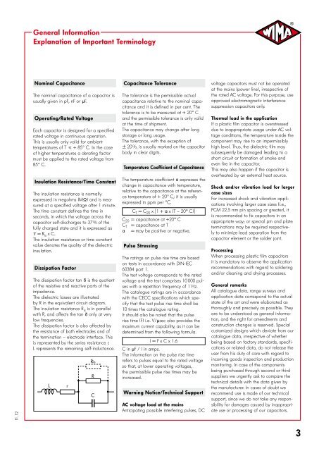
Dissipation Factor<br />
The dissipation factor tan d is the quotient<br />
of the resistive and reactive parts of the<br />
impedance.<br />
The dielectric losses are illustrated<br />
by R in the equivalent circuit diagram.<br />
The insulation resistance R is is in parallel<br />
with R, and affects the tan d only at very<br />
low frequencies.<br />
The dissipation factor is also affected by<br />
the resistance of both electrodes and of<br />
the termination – electrode interface. This<br />
is represented by the series resistance r.<br />
L represents the remaining self-inductance.<br />
L<br />
r<br />
Ris<br />
R<br />
C<br />
Capacitance Tolerance<br />
The tolerance is the permissible actual<br />
capacitance relative to the nominal capacitance<br />
and it is defined in per cent. The<br />
tolerance is to be measured at + 20) C<br />
and the permissible tolerance is only valid<br />
at the time of shipment.<br />
The capacitance may change after long<br />
storage or long usage.<br />
The tolerance, with the exception of<br />
p 20 %, is usually marked on the capacitor<br />
body in clear digits.<br />
Temperature Coefficient of Capacitance<br />
The temperature coefficient “ expresses the<br />
change in capacitance with temperature,<br />
relative to the capacitance at the reference<br />
temperature of + 20) C; it is usually<br />
expressed in ppm per )C.<br />
C T = C 20 x 1 + a x (T – 20+ C)<br />
C 20 = capacitance at +20+ C<br />
C T = capacitance at T<br />
a = may be positive or negative.<br />
Pulse Stressing<br />
The ratings on pulse rise time are based<br />
on tests in accordance with DIN-IEC<br />
60384 part 1.<br />
The test voltage corresponds to the rated<br />
voltage and the test comprises 10 000 pulses<br />
with a repetition frequency of 1 Hz.<br />
The catalogue ratings are in accordance<br />
with the CECC specifications which specify<br />
that the test pulse rise time shall be<br />
10 times the catalogue rating.<br />
It should also be noted that the pulse<br />
rise time (F) i.e. V/msec also provides the<br />
maximum current capability, as it can be<br />
determined from the following <strong>for</strong>mula.<br />
I = F x C x 1.6<br />
C in mF / I in amps.<br />
The in<strong>for</strong>mation on the pulse rise time<br />
refers to pulses equal to the rated voltage<br />
so that, at lower operating voltages,<br />
the permissible pulse rise times may be<br />
increased.<br />
Warning Notice/Technical Support<br />
AC voltage load at the mains<br />
Anticipating possible interfering pulses, DC<br />
voltage capacitors must not be operated<br />
at the mains (power line), irrespective of<br />
the rated AC voltage. For this purpose, use<br />
approved electromagnetic interference<br />
suppression capacitors only.<br />
Thermal load in the application<br />
If a plastic film capacitor is overstressed<br />
due to inappropriate usage under AC voltage<br />
conditions, the temperature inside the<br />
component may rise to an impermissibly<br />
high level. Thus, the dielectric film may<br />
subsequently be damaged leading to a<br />
short circuit or <strong>for</strong>mation of smoke and<br />
even fire in the capacitor.<br />
This may also happen if the capacitor is<br />
overheated by an external heat source.<br />
Shock and/or vibration load <strong>for</strong> larger<br />
case sizes<br />
For increased shock and vibration applications<br />
involving larger case sizes (i.e.,<br />
PCM 22.5 mm pin spacing or greater), it<br />
is recommended to fix capacitors in an<br />
appropriate way; or special pin and plate<br />
terminations may be required respectively<br />
to minimize lead separation from the<br />
capacitor element or the solder joint.<br />
Processing<br />
When processing plastic film capacitors<br />
it is mandatory to observe the application<br />
recommendations with regard to soldering<br />
and/or cleaning and drying processes.<br />
General remarks<br />
All catalogue data, range surveys and<br />
application data correspond to the actual<br />
state of the art and were elaborated as<br />
thoroughly and precisely as possible. They<br />
are to be understood as general in<strong>for</strong>mation,<br />
and the right <strong>for</strong> amendments and<br />
construction changes is reserved. Special<br />
customized designs which deviate from our<br />
catalogue data, irrespective of whether<br />
being based on factory standards, specifications<br />
or related data, do not release the<br />
user from his duty of care with regard to<br />
incoming goods inspection and production<br />
monitoring. In case of the components<br />
being purchased through second or third<br />
suppliers we urgently ask to compare the<br />
technical details with the data given by<br />
the manufacturer. In cases of doubt we<br />
recommend use is made of our technical<br />
support, since we do not take any responsibility<br />
<strong>for</strong> damages caused by inappropriate<br />
use or processing of our capacitors.