

308922B 495st Airless Paint Sprayers - Graco Inc.
308922B 495st Airless Paint Sprayers - Graco Inc.
308922B 495st Airless Paint Sprayers - Graco Inc.

You also want an ePaper? Increase the reach of your titles
YUMPU automatically turns print PDFs into web optimized ePapers that Google loves.
INSTRUCTIONS-REPAIR<br />
INSTRUCTIONS<br />
KEEP FOR REFERENCE.<br />
Read this and all related manuals for<br />
important warnings and instructions.<br />
First choice when<br />
quality counts.<br />
308922<br />
Rev. B<br />
Supercedes Rev. A<br />
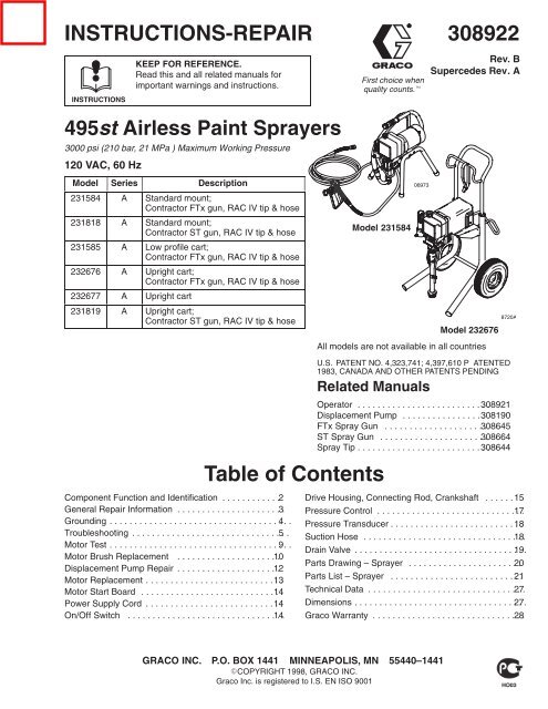
<strong>495st</strong> <strong>Airless</strong> <strong>Paint</strong> <strong>Sprayers</strong><br />
3000 psi (210 bar, 21 MPa ) Maximum Working Pressure<br />
120 VAC, 60 Hz<br />
Model Series Description<br />
231584 A Standard mount;<br />
Contractor FTx gun, RAC IV tip & hose<br />
231818 A Standard mount;<br />
Contractor ST gun, RAC IV tip & hose<br />
231585 A Low profile cart;<br />
Contractor FTx gun, RAC IV tip & hose<br />
232676 A Upright cart;<br />
Contractor FTx gun, RAC IV tip & hose<br />
232677 A Upright cart<br />
231819 A Upright cart;<br />
Contractor ST gun, RAC IV tip & hose<br />
Component Function and Identification . . . . . . . . . . . . 2<br />
General Repair Information . . . . . . . . . . . . . . . . . . . . . 3.<br />
Grounding . . . . . . . . . . . . . . . . . . . . . . . . . . . . . . . . . . 4. . .<br />
Troubleshooting . . . . . . . . . . . . . . . . . . . . . . . . . . . . . . 5. .<br />
Motor Test . . . . . . . . . . . . . . . . . . . . . . . . . . . . . . . . . . 9. . .<br />
Motor Brush Replacement . . . . . . . . . . . . . . . . . . . . 10 .<br />
Displacement Pump Repair . . . . . . . . . . . . . . . . . . . . 12 .<br />
Motor Replacement . . . . . . . . . . . . . . . . . . . . . . . . . . 13 . .<br />
Motor Start Board . . . . . . . . . . . . . . . . . . . . . . . . . . . 14 . .<br />
Power Supply Cord . . . . . . . . . . . . . . . . . . . . . . . . . . 14 . .<br />
On/Off Switch . . . . . . . . . . . . . . . . . . . . . . . . . . . . . . 14 . .<br />
Model 231584<br />
Related Manuals<br />
Table of Contents<br />
<br />
Model 232676<br />
All models are not available in all countries<br />
U.S. PATENT NO. 4,323,741; 4,397,610 P ATENTED<br />
1983, CANADA AND OTHER PATENTS PENDING<br />
8720A<br />
Operator . . . . . . . . . . . . . . . . . . . . . . . . . 308921 . .<br />
Displacement Pump . . . . . . . . . . . . . . . . 308190 .<br />
FTx Spray Gun . . . . . . . . . . . . . . . . . . . . 308645 .<br />
ST Spray Gun . . . . . . . . . . . . . . . . . . . . . 308664 .<br />
Spray Tip . . . . . . . . . . . . . . . . . . . . . . . . . 308644 . .<br />
Drive Housing, Connecting Rod, Crankshaft . . . . . . 15<br />
Pressure Control . . . . . . . . . . . . . . . . . . . . . . . . . . . . 17 . .<br />
Pressure Transducer . . . . . . . . . . . . . . . . . . . . . . . . . 18 . .<br />
Suction Hose . . . . . . . . . . . . . . . . . . . . . . . . . . . . . . . 18 . .<br />
Drain Valve . . . . . . . . . . . . . . . . . . . . . . . . . . . . . . . . . 19 . .<br />
Parts Drawing – Sprayer . . . . . . . . . . . . . . . . . . . . . . 20 .<br />
Parts List – Sprayer . . . . . . . . . . . . . . . . . . . . . . . . . 21 . .<br />
Technical Data . . . . . . . . . . . . . . . . . . . . . . . . . . . . . . 27 . .<br />
Dimensions . . . . . . . . . . . . . . . . . . . . . . . . . . . . . . . . . 27 . .<br />
<strong>Graco</strong> Warranty . . . . . . . . . . . . . . . . . . . . . . . . . . . . . 28 . .<br />
GRACO INC. P.O. BOX 1441 MINNEAPOLIS, MN 55440–1441<br />
COPYRIGHT 1998, GRACO INC.<br />
<strong>Graco</strong> <strong>Inc</strong>. is registered to I.S. EN ISO 9001
Component Identification and Function<br />
P<br />
H<br />
J<br />
C<br />
L<br />
E<br />
G<br />
A<br />
P<br />
F<br />
M<br />
N<br />
D<br />
B<br />
H<br />
K<br />
Fig. 1<br />
L<br />
Model 231584 Shown<br />
06973<br />
A Motor DC motor, 120 Vac, 15A, 1 phase<br />
B Drive Assembly Transfers power from DC motor to the displacement pump<br />
C Pressure Adjusting Knob Controls fluid outlet pressure<br />
D ON/OFF Switch Power switch that controls 120 Vac power to sprayer<br />
E Fluid Outlet Hose and spray gun is connected here<br />
F Displacement Pump Pressurizes fluid to be sprayed through spray gun<br />
G 50 ft (15 m) Main Hose 1/4 in. ID, grounded, nylon hose with spring guards on both ends<br />
H RAC IV Tip Guard Reverse-A-Clean (RAC) tip guard reduces the risk of fluid injection injury<br />
J Contractor ST Gun High pressure spray gun with gun safety latch<br />
K Contractor FTx Gun High pressure spray gun with gun safety latch<br />
L RAC IV Switch Tip RAC switch tip atomizes fluid and removes clogs from spray tip without<br />
removing tip from spray gun<br />
M Pressure Drain Valve Relieves fluid pressure when open<br />
N Pressure Control Controls motor to maintain fluid pressure. Works with pressure<br />
adjusting knob.<br />
P Spray Gun Safety Latch Inhibits accidental triggering of spray gun
General Repair Information<br />
CAUTION<br />
To reduce risk of pressure control malfunction:<br />
Use needle nose pliers to disconnect a wire. Never<br />
pull on wire, pull on connector.<br />
<br />
Mate wire connectors properly. Center flat blade of<br />
insulated male connector in female connector.<br />
Route wires carefully to avoid interference with<br />
other connections of pressure control. Do not pinch<br />
wires between cover and control box.<br />
Tool List<br />
Phillips screwdriver<br />
Small flat blade<br />
screwdriver<br />
Needle nose pliers<br />
Plastic mallet or 20 oz<br />
(max) hammer<br />
12 in. adjustable wrench<br />
Adjustable, open-end<br />
wrench<br />
Torque wrench<br />
1/4 in. hex key wrench<br />
3/16 in. hex key wrench<br />
5/8 in. socket wrench<br />
3/8 in. open end wrench<br />
1/2 in. open end wrench<br />
3/4 in. open end wrench<br />
7/8 in. open end wrench<br />
High quality motor oil<br />
Bearing grease<br />
1. Keep all screws, nuts, washers, gaskets, and<br />
electrical fittings removed during repair procedures.<br />
These parts are not normally provided with<br />
replacement assemblies.<br />
WARNING<br />
ELECTRIC SHOCK HAZARD<br />
To reduce risk of serious injury, including<br />
electric shock, do not touch moving or<br />
electrical parts with fingers or tools while<br />
testing repair. Shut off and unplug sprayer when<br />
inspection is complete. Install all covers, gaskets,<br />
screws and washers before operating sprayer.<br />
2. Test repair after problem is corrected.<br />
3. If sprayer does not operate properly, review<br />
repair procedure to verify procedure was done<br />
correctly. If necessary, see Troubleshooting Guide,<br />
pages 5 – NO TAG, for other possible solutions.<br />
WARNING<br />
EXPLOSION HAZARD<br />
Motor and drive housing are very hot<br />
during operation and could burn skin if<br />
touched. Flammable materials spilled on<br />
hot, bare motor could cause fire or explosion. Have<br />
motor shield in place during operation to reduce<br />
risk of burns, fire or explosion.<br />
CAUTION<br />
Do not run sprayer dry for more than 30 seconds to<br />
avoid damaging pump packings.<br />
4. Install motor shield before operation of sprayer<br />
and replace if damaged. Motor shield directs<br />
cooling air around motor to prevent overheating. It<br />
can also reduce risk of burns, fire or explosion; see<br />
preceding WARNING.<br />
Pressure Relief Procedure<br />
WARNING<br />
INJECTION HAZARD<br />
System pressure must be manually<br />
relieved to prevent system from starting<br />
or spraying accidentally. Fluid under high<br />
pressure can be injected through skin and cause<br />
serious injury. To reduce risk of injury from injection,<br />
splashing fluid, or moving parts, follow Pressure<br />
Relief Procedure whenever you:<br />
are instructed to relieve pressure,<br />
stop spraying,<br />
check or service any system equipment,<br />
or install or clean spray tip.<br />
1. Lock gun safety latch.<br />
2. Turn ON/OFF switch to OFF.<br />
3. Unplug power supply cord.<br />
4. Unlock gun safety latch. Hold metal part of gun<br />
firmly to grounded metal pail. Trigger gun to relieve<br />
pressure.<br />
5. Lock gun safety latch.<br />
6. Open pressure drain valve. Leave pressure drain<br />
valve open until ready to spray again.<br />
If suspected that spray tip or hose is completely<br />
clogged, or that pressure has not been fully relieved<br />
after following steps above, VERY SLOWLY loosen tip<br />
guard retaining nut or hose end coupling to relieve<br />
pressure gradually, then loosen completely. Now clear<br />
tip or hose obstruction.
Grounding<br />
WARNING<br />
Improper installation or alteration of grounding plug<br />
results in risk of electric shock, fire or explosion<br />
that could cause serious injury or death.<br />
Grounded<br />
Outlets<br />
1. Models 231584, 231818, 231585, 232676, 232677<br />
and 231819 require a 120 VAC, 50/60 Hz, 15A<br />
circuit with a grounding receptacle. See Fig. 2.<br />
2. Do not alter ground prong or use adapter.<br />
Fig. 23<br />
Grounding Prong<br />
3. A 12 AWG, 3 wires with grounding prong, 300 ft<br />
(90 m) extension cord may be used. Long lengths<br />
reduce sprayer performance.
Troubleshooting<br />
Relieve pressure; page 3.<br />
Basic Problem Solving<br />
Check everything in the troubleshooting table before disassembling the sprayer.<br />
TYPE OF PROBLEM<br />
WHAT TO CHECK<br />
If check is OK, go to next check<br />
WHAT TO DO<br />
When check is not OK, refer to this column<br />
Fluid pressure 1. Pressure control knob setting. The pump won’t<br />
develop much pressure if it is at minimum setting<br />
(fully counterclockwise).<br />
2. For clogged spray tip or fluid filter, if used. See<br />
manual 308645 or 308664.<br />
1. Slowly increase pressure setting to see if<br />
motor starts.<br />
2. If tip is still clogged, relieve pressure; refer<br />
to separate gun or tip instruction manual<br />
for tip cleaning. Clean or replace filter<br />
element. See manual 308249.<br />
Mechanical<br />
1. For frozen or hardened paint in pump (20). Using<br />
a screwdriver, carefully try to rotate fan at<br />
back of motor by hand. See page 9.<br />
2. Displacement pump connecting rod pin (17).<br />
Pin must be completely pushed into connecting<br />
rod (15), and retaining spring (18) must be<br />
firmly in connecting rod groove. See Fig. 10,<br />
page 12.<br />
3. For motor damage. Remove drive housing assembly<br />
(11). See page 15. Try to rotate motor<br />
fan by hand.<br />
1. Thaw sprayer if water or water-based<br />
paint has frozen in sprayer. Place sprayer<br />
in warm area to thaw. Do not start<br />
sprayer until thawed completely. If paint<br />
hardened (dried) in sprayer, replace<br />
pump packings. See page 12<br />
(Displacement Pump Repair).<br />
2. Push pin into place and secure with<br />
spring retainer.<br />
3. Replace motor (4) if fan won’t turn. See<br />
page 13.<br />
Electrical 1. Electrical supply. Meter must read:<br />
100–120 VAC for models 231584, 231818,<br />
231585, 232676, 232677 and 231819.<br />
2. Extension cord for visible damage. Use a volt<br />
meter or test lamp at extension cord outlet to<br />
check.<br />
3. Sprayer power supply cord (50) for visible damage<br />
such as broken insulation or wires.<br />
4. Check motor brushes for the following:<br />
a. Loose terminal screws.<br />
b. Broken or misaligned brush springs.<br />
c. Brushes binding in holders.<br />
d. Broken leads.<br />
e. Worn brushes.<br />
NOTE: The brushes do not wear at same rate<br />
on both sides of motor. Check both brushes.<br />
1. Reset building circuit breaker; replace<br />
building fuse. Try another outlet.<br />
2. Replace extension cord.<br />
3. Replace power supply cord.<br />
See page 14.<br />
4. Refer to page 10.<br />
a. Tighten.<br />
b. Replace broken spring and/or align<br />
spring with brush<br />
c. Clean brush holders. Remove carbon<br />
with small cleaning brush. Align brush<br />
leads with slot in brush holder to assure<br />
free vertical brush movement.<br />
d. Replace brushes<br />
e. Replace brushes if less than 0.5 in.<br />
long.
Basic Problem Solving<br />
TYPE OF PROBLEM<br />
WHAT TO CHECK<br />
If check is OK, go to next check<br />
Electrical (continued) 5. Motor armature commutator for burn spots,<br />
gouges and extreme roughness. Remove motor<br />
cover and brush inspection plates to check.<br />
See page 10.<br />
6. Motor armature for shorts using armature tester<br />
(growler) or perform motor test.<br />
See page 9.<br />
7. Leads from pressure control and motor to motor<br />
start board (47) to be sure they are securely<br />
fastened and properly mated.<br />
8. Motor start board (47) by substituting with a<br />
good board. See page 14.<br />
WHAT TO DO<br />
When check is not OK, refer to this column<br />
5. Remove motor and have motor shop<br />
resurface commutator if possible. See<br />
page 13.<br />
6. Replace motor. See page 13.<br />
7. Replace loose terminals; crimp to leads.<br />
Be sure male terminal blades are straight<br />
and firmly connected to mating part.<br />
8. Replace board. See page 14.<br />
CAUTION: Do not perform this check until motor<br />
armature is determined to be good. A bad<br />
motor armature can burn out a good board.<br />
9. Power supply cord (50). Disconnect black and<br />
white power cord terminals; connect volt meter<br />
to these leads. Plug in sprayer. Meter must<br />
read: 100–120 VAC for models 231584,<br />
231818, 231585, 232676, 232677 and 231819.<br />
Unplug sprayer.<br />
10. ON/OFF switch (52). Disconnect the motor start<br />
board (47) and switch and connect volt meter<br />
between exposed terminal on switch and power<br />
cord’s white wire. Plug in sprayer and turn ON.<br />
Meter must read: 100–120 VAC for models<br />
231584, 231818, 231585, 232676, 232677 and<br />
231819.<br />
11. Motor thermal cutout switch. Connect ohmmeter<br />
between motor’s red leads. Meter should<br />
read 1 ohm maximum.<br />
12. Remove pressure control (64) and check microswitch<br />
operation with ohmmeter:<br />
(1) With pressure knob at lowest setting and<br />
stem pushed into control, readings should<br />
be: white & black = 1 ohm max.<br />
white & red = open.<br />
(2) With pressure knob at highest setting,readings<br />
should be: white & black = open;<br />
white & red = 1 ohm max.<br />
13. Pressure transducer (29) for hardened paint or<br />
damaged or worn components. See page 18.<br />
9. Replace power supply cord. See page<br />
14.<br />
10. Replace ON/OFF switch. See page 14.<br />
11. Allow motor to cool. Correct cause of<br />
overheating. If switch remains open after<br />
motor cools, replace motor.<br />
12. Replace pressure control. See page 17.<br />
13. Replace transducer. See page 18. Thorough<br />
system flushing will help extend life<br />
of transducer.<br />
TYPE OF PROBLEM<br />
Intermediate Problem Solving<br />
WHAT TO CHECK<br />
If check is OK, go to next check<br />
WHAT TO DO<br />
When check is not OK refer to this column<br />
Low output 1. For worn spray tip. 1. Follow Pressure Relief Procedure then<br />
replace tip. See your separate gun or tip<br />
manual.<br />
2. Be sure pump does not continue to stroke<br />
when gun trigger is released. Plug in and turn<br />
on sprayer. Prime with paint. Trigger gun momentarily,<br />
then release and lock safety latch.<br />
Relieve pressure, turn off and unplug sprayer.<br />
2. Service pump. See page 12.
Intermediate Problem Solving<br />
TYPE OF PROBLEM<br />
WHAT TO CHECK<br />
If check is OK, go to next check<br />
Low output (continued) 3. Release gun trigger. Observe resting position of<br />
pump rod (107).<br />
4. Electrical supply. Meter must read:<br />
100–120 VAC for models 231584, 231818,<br />
231585, 232676, 232677 and 231819.<br />
5. Extension cord size and length; must be at<br />
least 12 gauge wire and less than 150 ft<br />
(45 m) long.<br />
6. Motor brushes. See Electrical – What To<br />
Check, item 4, on page 5.<br />
7. Motor start board (47) by substituting with a<br />
good board.<br />
WHAT TO DO<br />
When check is not OK, refer to this column<br />
3. If pump consistently comes to rest with<br />
rod (107) fully extended, the piston packings<br />
and/or piston valve may be worn.<br />
Service the pump. See page 12.<br />
4. Reset building circuit breaker; replace<br />
building fuse. Repair electrical outlet or<br />
try another outlet.<br />
5. Replace with a correct, grounded extension<br />
cord.<br />
6. See page 10.<br />
7. Replace board. See page 14.<br />
CAUTION: Do not perform this check until motor<br />
armature is determined to be good. A bad<br />
motor armature can burn out a good board.<br />
8. Motor armature for shorts by using an armature<br />
tester (growler) or perform motor test. See page<br />
9.<br />
8. Replace motor. See page 13.<br />
Drain valve leaks 1. Drain valve for correct torque and/or worn<br />
parts. Check for debris trapped on seat.<br />
9. Tighten to 185 in–lb (21 N.m). Clean<br />
valve and replace with new gasket (42a)<br />
and sealant (42d). See page 19.<br />
Transducer leaks 1. Slight leakage from transducer is normal. 1. Periodically remove residue from its cylinder<br />
port. See page 18.<br />
No output: motor runs and<br />
pump strokes<br />
1. <strong>Paint</strong> supply. 1. Refill and reprime pump.<br />
2. For clogged intake strainer. 2. Remove and clean, then reinstall.<br />
3. For loose suction tube or fittings. See<br />
page 18.<br />
4. To see if intake valve ball and piston ball are<br />
seating properly. See page 12.<br />
5. For leaking around throat packing nut which<br />
may indicate worn or damaged packings. See<br />
page 12.<br />
3. Tighten; use thread sealant on npt<br />
threads of adapter (38).<br />
4. Remove intake valve and clean. Check<br />
ball and seat for nicks; replace as needed.<br />
See page 12. Strain paint before using<br />
to remove particles that could clog<br />
pump.<br />
5. Replace packings. See page 12. Also<br />
check piston valve seat for hardened<br />
paint or nicks and replace if necessary.<br />
Tighten packing nut/wet-cup.<br />
No output: motor runs but<br />
pump does not stroke<br />
6. Release gun trigger. Observe resting position of<br />
pump rod (107).<br />
1. Displacement pump connecting rod pin (17).<br />
See Fig. 10, page 12.<br />
7. Connecting rod assembly (15) for damage.<br />
See page 15.<br />
8. Be sure crank in drive housing rotates; plug in<br />
sprayer and turn on briefly to check. Turn off<br />
and unplug sprayer. See page 15.<br />
6. If pump consistently comes to rest with<br />
rod (107) fully extended, the piston packings<br />
and/or piston valve may be worn.<br />
Service the pump. See page 12.<br />
1. Replace pin if missing. Be sure retainer<br />
spring (18) is fully in groove all around<br />
connecting rod.<br />
7. Replace connecting rod assembly. See<br />
page 15.<br />
8. Check drive housing assembly for<br />
damage and replace if necessary. See<br />
page 15.
Intermediate Problem Solving<br />
TYPE OF PROBLEM<br />
WHAT TO CHECK<br />
If check is OK, go to next check<br />
WHAT TO DO<br />
When check is not OK, refer to this column<br />
Spray Pattern Variations 1. Spray tip worn beyond sprayer pressure capability.<br />
1. Replace spray tip.<br />
NOTE: A smaller size tip will provide<br />
longer life.<br />
2. Transducer (29) for wear or damage. 2. Replace transducer. See page 18.<br />
3. Pressure control (64) for smooth operation. 3. Replace pressure control. See page 17.<br />
4. Low output section, page 7.<br />
Motor Is Hot and Runs<br />
Intermittently<br />
1. Determine if sprayer was operated at high pressure<br />
with small tips, which causes excessive<br />
heat build up.<br />
2. Be sure ambient temperature where sprayer is<br />
located is no more than 90F (32C) and<br />
sprayer is not located in direct sun.<br />
1. Decrease pressure setting or increase tip<br />
size.<br />
2. Move sprayer to shaded, cooler area if<br />
possible.<br />
3. Motor. 3. Replace motor. See page 13.<br />
Building Circuit Breaker<br />
Opens As Soon As<br />
Sprayer Switch Is<br />
Turned On.<br />
Circuit breaker opens<br />
after sprayer operates<br />
for 5 to 10 minutes.<br />
Building circuit breaker<br />
opens as soon as sprayer<br />
is plugged into outlet and<br />
sprayer is NOT turned on.<br />
Unit will not run on generator<br />
but does run on AC<br />
power<br />
1. All electrical wiring for damaged insulation, and<br />
all terminals for loose fit or damage. Also check<br />
wires between pressure control and motor. See<br />
page 13.<br />
2. For missing motor brush inspection plate gasket<br />
(see page 9), bent terminal forks or other<br />
metal to metal contact points which could<br />
cause a short.<br />
3. Motor armature for shorts. Use an armature<br />
tester (growler) or perform motor test. See page<br />
9. Inspect windings for burns.<br />
4. Motor start board (47) by substituting with a<br />
good board.<br />
CAUTION: Do not perform this check until<br />
motor armature is determined to be good. A<br />
bad motor armature can burn out a good board.<br />
1. Basic Problems – Electrical on page 5.<br />
1. ON/OFF switch (52). Be sure sprayer is unplugged!<br />
Disconnect wires from switch. Check<br />
switch with ohmmeter. The reading should be<br />
infinity with ON/OFF switch OFF, and zero with<br />
switch ON.<br />
CAUTION: A short in motor circuit can damage<br />
switch and or motor start board (47).<br />
2. Electrical supply. Meter must read:<br />
100–120 VAC for models 231584, 231818,<br />
231585, 232676, 232677 and 231819.<br />
Generator peak voltage. Models 231584, 231818,<br />
231585, 232676, 232677 and 231819 will not run if<br />
the peak voltage is above 190V.<br />
1. Repair or replace any damaged wiring or<br />
terminals. Securely reconnect all wires.<br />
2. Correct faulty conditions.<br />
3. Replace motor. See page 13.<br />
4. Replace board. See page 14.<br />
1. Replace ON/OFF switch. See page 14.<br />
2. If voltage is too high, do not operate<br />
sprayer until corrected.<br />
Use AC power or a different generator
Motor Test<br />
Relieve pressure; page 3.<br />
For checking armature, motor winding and brush<br />
electrical continuity.<br />
Setup<br />
Remove the drive housing. See page 15. This is to<br />
ensure that any resistance you notice in the armature<br />
test is due to the motor and not to worn gears in the<br />
drive housing.<br />
B<br />
Remove the motor brush inspection covers (A). See<br />
Fig. 4.<br />
A<br />
Remove the junction box screws (56). Lower the<br />
junction box. Disconnect the two leads (C) from the<br />
motor to the board (47). See Fig. 5.<br />
Armature Short Circuit Test<br />
Remove the fan cover (B). See Fig. 4.<br />
Spin the motor fan by hand. If there are no shorts, the<br />
motor will coast two or three revolutions before coming<br />
to a complete stop. If the motor does not spin freely,<br />
the armature is shorted and the motor must be replaced.<br />
See page 13.<br />
Fig. 4<br />
Model 231584 Shown<br />
MOTOR<br />
06975<br />
Armature, Brushes, and Motor Wiring<br />
Open Circuit Test (Continuity)<br />
Connect the two black motor leads together with a test<br />
lead. Turn the motor fan by hand at about two revolutions<br />
per second.<br />
When turning the fan on a DC motor, normally you<br />
sense an even, pulsing resistance. If there is irregular<br />
turning resistance, or no turning resistance, check and<br />
repair the following as needed: broken brush springs,<br />
brush leads, motor leads; loose brush terminal screws<br />
or motor lead terminals; worn brushes. See page 10.<br />
59<br />
BLACK/<br />
WHITE<br />
BLACK<br />
C<br />
RED<br />
56<br />
If there is still uneven or no turning resistance, replace<br />
the motor. See page 13.<br />
Fig. 5<br />
47<br />
04720
Motor Brush Replacement<br />
NOTE: Replace brushes when worn to about 0.5 in.<br />
(12.5 mm). Always check both brushes. Brush Repair<br />
Kit 236–967, which includes spring clip 112–766, is<br />
available for motors manufactured by Pacific Scientific.<br />
<br />
<br />
<br />
Motor lead; do not disconnect<br />
Minimum 0.5” (12.5 mm)<br />
<strong>Inc</strong>luded in Brush Repair<br />
Kit 236–967<br />
NOTE: Replacement brushes may last only half as<br />
long as the original ones. To maximize brush life, break<br />
in new brushes by operating the sprayer for at least<br />
one hour with no load (remove the pump connecting<br />
rod pin).<br />
<br />
F<br />
G<br />
H<br />
<br />
C<br />
<br />
B<br />
Relieve pressure; page 3.<br />
1. Remove both inspection covers (A) and their<br />
gaskets. See Fig 6.<br />
Fig. 7<br />
D<br />
E<br />
<br />
4. Inspect the commutator for excessive pitting,<br />
burning or gouging. A black color on the commutator<br />
is normal. Have the commutator resurfaced by<br />
a qualified motor repair shop if the brushes seem<br />
to wear too fast or arc excessively. See Step 9.d.,<br />
also.<br />
5. Repeat for the other side.<br />
NOTE: The motor brushes on the other side are<br />
upside down.<br />
6. Place a new brush (C) in the holder (B) so the<br />
ramp (H) faces the spring. See Fig. 16.<br />
A<br />
<br />
F<br />
G<br />
Fig. 6<br />
02831A<br />
C<br />
2. Push in the spring clip (F) and release its hook (G)<br />
from the brush holder (B). Pull out the spring clip.<br />
See Fig 7.<br />
3. Slide off the brush lead terminal (E) off the blade<br />
connector. Remove the old brush (C). See Fig 7.<br />
Fig. 8<br />
<br />
7. Holding the spring clip (F) at a slight angle, slide<br />
the spring clip into the brush holder and hook it<br />
over the end of the holder. See Fig. 8. Pull on the<br />
spring clip to be sure it stays in place. Connect the<br />
brush lead to the blade connector (E).<br />
8. Repeat for the other side.<br />
E
Motor Brush Replacement<br />
9. Test the brushes.<br />
a. Remove the pump connecting rod pin (17).<br />
See Fig. 10, page 12.<br />
b. With the sprayer OFF, turn the pressure control<br />
knob fully counterclockwise to minimum<br />
pressure. Plug in the sprayer.<br />
c. Turn the sprayer ON. Slowly increase the<br />
pressure until the motor is at full speed.<br />
d. Inspect the brush and commutator contact area<br />
for excessive arcing. Arcs should not trail or<br />
circle around the commutator surface.<br />
WARNING<br />
MOVING PARTS HAZARD<br />
Do not touch the brushes, leads, springs<br />
or brush holders while the sprayer is<br />
plugged in to reduce the risk of electric<br />
shock and serious injury.<br />
10. Install the brush inspection covers and gaskets.<br />
11. Break in the brushes. Operate the sprayer for at<br />
least one hour with no load. Install the pump<br />
connecting rod pin. See Fig. 10, page 12.
Displacement Pump Repair<br />
Relieve pressure; page 3.<br />
NOTE: Packing Repair Kit 235703 is available. Reference<br />
numbers of parts included in the kit are marked<br />
with an asterisk, i.e., (121*). For the best results, use<br />
all the new parts in the kit, even if the old ones still look<br />
good.<br />
NOTE: To minimize down time, and for the best sprayer<br />
performance, check the motor brushes (see page 10)<br />
and clean the transducer (see page 18) whenever you<br />
repack the pump. Replace these parts as needed.<br />
2. Align the hole in the rod (107) with the connecting<br />
rod assembly (15). Use a screwdriver to push the<br />
retaining spring (18) up and push in the pin (17).<br />
Push the retaining spring (18) into place around<br />
the connecting rod.<br />
3. Replace the o-ring (27) if it is worn or damaged.<br />
Reconnect the suction and drain hoses (32,33).<br />
Install the front cover (13).<br />
4. Tighten the packing nut (102) just enough to stop<br />
leakage, but no tighter. Fill the packing nut/wet-cup<br />
1/3 full with <strong>Graco</strong> TSL. Push the plug (123) into<br />
the wet-cup.<br />
Removing the pump (See Fig. 9.)<br />
1. Flush the pump, if possible. Relieve pressure. Stop<br />
the pump with the piston rod (107) in its lowest<br />
position, if possible. To lower the piston rod manually,<br />
rotate the motor fan blades.<br />
2. Remove the filter (85).<br />
3. Remove suction hose or tube (32).(For suction<br />
hose, refer to page 18.<br />
4. Use a screwdriver to push the retaining spring (18)<br />
up and push out the pin (17).<br />
5. Loosen the screws (21). Remove the pump (20).<br />
Repairing the pump<br />
See manual 308190 for pump repair instructions.<br />
Installing the pump (See Fig. 9 and 10.)<br />
1. Mount the pump on the drive housing. Tap it into<br />
the alignment pins with a soft hammer. Tighten the<br />
screws (21) to 50 ft-lb (68 N.m).<br />
WARNING<br />
MOVING PARTS HAZARD<br />
Be sure the retaining spring (18) is firmly<br />
in the groove all the way around, to prevent<br />
the pin (17) from working loose due<br />
to vibration. See Fig. 10.<br />
If the pin works loose, it or other parts could break<br />
off due to the force of the pump action. These parts<br />
could be projected into the air and result in serious<br />
injury or property damage, including the pump<br />
connecting rod or drive housing.<br />
<br />
13<br />
Fig. 9<br />
<br />
<br />
21<br />
18<br />
107<br />
33<br />
32<br />
27<br />
38<br />
Fig. 10<br />
20<br />
<br />
15<br />
85<br />
123<br />
Torque to<br />
50 ft–lb (68 N.m)<br />
36<br />
118<br />
<br />
<br />
17<br />
120<br />
*122<br />
*121<br />
*119<br />
Torque to<br />
50 ft–lb (68 N.m)<br />
Apply anaerobic<br />
polycrystal pipe<br />
sealant<br />
Model 231584 Shown<br />
21 <br />
17<br />
18<br />
102<br />
02832B
Motor Replacement<br />
Relieve pressure; page 3.<br />
NOTE: See Fig. 13 except where noted.<br />
1. Relieve pressure.<br />
2. Try to stop the pump with the piston rod (107) in its<br />
lowest position. To lower the piston rod manually,<br />
rotate the motor fan blades. Use a screwdriver to<br />
push the retaining spring (18) up and push out the<br />
pin (17). See Fig. 11.<br />
3. Remove the screws (56) and lower the junction<br />
box (59). Disconnect the motor wires and the<br />
pressure control wire (A) from the motor start<br />
board. Refer to Fig. 14 on page 14.<br />
4. Remove the front cover (13).<br />
5. Turn the displacement pump rod (107) so the pin<br />
hole aligns with the bottom drive housing screw<br />
(19). See Fig. 12. Remove the three drive housing<br />
screws and lockwashers (19,6). Also see Fig. 13.<br />
6. Remove the two motor screws (5) and the lock<br />
washers (6).<br />
7. Tap the lower rear of the drive housing (11) with a<br />
plastic mallet to loosen the motor. Pull the drive<br />
housing straight off the motor while guiding the<br />
harness (A) from the motor. Do not allow the gear<br />
(16) to fall. Read the CAUTION on page 15.<br />
8. Remove the two screws (46) and lift the motor off<br />
the base (66).<br />
9. Align the new motor with the base and reinstall the<br />
screws (46).<br />
11<br />
10. Assemble the drive housing to the motor. Follow<br />
steps 8 to 10 on page 15.<br />
11. Connect the wires in the junction box. Refer to Fig.<br />
14 on page 14. Install the junction box.<br />
12. Connect the piston rod (107) to the drive housing;<br />
see page 12, Installing the Pump , Step 2 and the<br />
WARNING following it.<br />
15<br />
Fig. 11<br />
01068<br />
Fig. 12<br />
12<br />
A<br />
107<br />
C<br />
B<br />
<br />
5<br />
6<br />
4<br />
17<br />
18<br />
19,6<br />
01074<br />
<br />
<br />
Torque to 2.4 N.m (21 in–lb)<br />
Quantity of three<br />
<br />
Quantity of one<br />
6<br />
16<br />
<br />
19<br />
13<br />
59<br />
46<br />
<br />
31<br />
56<br />
Fig. 13<br />
34<br />
<br />
05119
Motor Start Board<br />
Relieve pressure; page 3.<br />
NOTE: See Fig. 14 for this procedure.<br />
1. Relieve pressure.<br />
2. Remove the junction box screws (56) and lower<br />
the junction box (59).<br />
3. Disconnect the motor wires (B) and the 3-wire<br />
connector (A) from the motor start board (47).<br />
Observe where connections are made.<br />
4. Remove the screws (58) and motor start board<br />
(47). Transfer the white thermal paste from the old<br />
board to the new board.<br />
5. Install the new motor start board. Reconnect all<br />
wires. Install the junction box. Be sure no leads are<br />
pinched against the motor or by the motor start<br />
board. Also be sure the gasket (89) is installed.<br />
CAUTION<br />
Be sure the flat blade of the insulated male connector<br />
is centered in the wrap–around blade of the<br />
female connector when the connections are made.<br />
Route all wires carefully to avoid interference with<br />
the motor start board or junction box.<br />
These precautions are essential to reduce the risk of<br />
a malfunction.<br />
Power Supply Cord<br />
NOTE: See Fig. 14 for this procedure.<br />
1. Relieve pressure.<br />
2. Remove the junction box screws (56) and lower<br />
the junction box (59).<br />
3. Disconnect the power supply cord leads, including<br />
the green wire to the grounding screw (49).<br />
4. Loosen the strain relief bushing (51). Remove the<br />
power supply cord (50).<br />
5. Install the new cord (50) in the reverse order of<br />
disassembly.<br />
6. Install the junction box. Be sure no leads are<br />
pinched against the motor or by the motor start<br />
board. Also be sure the gasket (89) is installed.<br />
On/Off Switch<br />
NOTE: See Fig. 14 for this procedure.<br />
1. Relieve pressure.<br />
2. Remove the junction box screws (56) and lower<br />
the junction box (59).<br />
3. Remove the nut and rubber boot (55).<br />
4. Disconnect the black wires from the ON/OFF<br />
switch (52) and remove the switch.<br />
5. Place the ring terminal of the ground wire (53) over<br />
the barrel of the new switch. Install the switch so<br />
the internal tab of the anti-rotation ring (54) engages<br />
with the vertical groove in the threads of the<br />
switch, and the external tab engages with the blind<br />
hole (C) of the junction box.<br />
6. Powder the inside of the rubber boot (55) with<br />
talcum, then shake the excess out of the boot.<br />
Install the nut and rubber boot and tighten.<br />
7. Reconnect the ON/OFF switch black wires.<br />
8. Install the junction box. Be sure no leads are<br />
pinched against the motor or by the motor start<br />
board. Also be sure the gasket (89) is installed.<br />
59<br />
58<br />
BLACK/<br />
WHITE<br />
BLACK<br />
B<br />
Fig. 14<br />
MOTOR<br />
47<br />
GREEN<br />
49<br />
A<br />
RED<br />
GREEN/<br />
53 YELLOW<br />
50<br />
51<br />
89<br />
52<br />
56<br />
C<br />
54<br />
55
Drive Housing, Connecting Rod, Crankshaft<br />
Relieve pressure; page 3.<br />
Removal<br />
NOTE: Inspect parts as they are removed. Replace<br />
parts that are worn or damaged.<br />
1. Remove the displacement pump. See page 12.<br />
2. Remove the pressure control (64). See page 17.<br />
3. Turn the displacement pump rod (107) so the pin<br />
hole aligns with the bottom drive housing screw<br />
(19). See Fig. 15. Remove the three drive housing<br />
screws and lockwashers (19,6). Also see Fig. 16<br />
on page 16.<br />
107<br />
19,6<br />
Fig. 15<br />
01074<br />
4. Remove the two motor screws (5) and lock washers<br />
(6). See Fig. 16 on page 16.<br />
5. Tap the lower rear of the drive housing (11) with a<br />
plastic mallet to loosen the motor. Pull the drive<br />
housing straight off the motor.<br />
CAUTION<br />
Do not allow the gear (16) to fall; it may stay attached<br />
to the drive housing or to the motor.<br />
Do not lose the thrust balls (11a or 4a) or let them fall<br />
between the gears, which will damage the drive housing<br />
if not removed. The balls, which are heavily covered<br />
with grease, usually stay in the gear recesses, but<br />
could be dislodged. If the balls are not in place, the<br />
bearings will wear prematurely.<br />
6. Remove and inspect the crankshaft (12) and the<br />
connecting rod (15).<br />
Installation<br />
7. Install the connecting rod.<br />
8. Lubricate the inside of the drive housing bearing<br />
with SAE non-detergent oil. Pack the roller bearing<br />
and gears with the grease supplied.<br />
NOTE: The gears and bearings between the drive<br />
housing (11) and motor front end bell (C) should contain<br />
a total of 3 fl. oz. (29 cc) of grease.<br />
9. Place the large washer (12a) and then the small<br />
washer (12b) on the crankshaft (12).<br />
10. Lift the crank to the top of the stroke and insert<br />
crankshaft (12). Align the gears and push the drive<br />
housing (11) straight onto the motor and the locating<br />
pins. Install the screws (19, 5) and their lockwashers<br />
(6). Torque to 80 in–lb (9 N.m).<br />
11. Install the displacement pump. See page 12.<br />
12. Install the pressure control (64). See page 17.<br />
Install the front cover (13).
Drive Housing, Connecting Rod, Crankshaft<br />
<br />
64<br />
C<br />
4a<br />
12b<br />
REF A 16<br />
11a<br />
12<br />
12a<br />
5,6<br />
<br />
<br />
<br />
<br />
Torque to 2.4 N.m (21 in–lb)<br />
Quantity of three<br />
Quantity of one<br />
Apply a total of 3 fl. oz.(29 cc)<br />
of grease to gears.<br />
A<br />
47<br />
59<br />
Fig. 16<br />
Note: Filter<br />
not shown<br />
<br />
31<br />
34<br />
<br />
13<br />
15<br />
19<br />
<br />
6<br />
11<br />
56<br />
02815
Pressure Control<br />
Relieve pressure; page 3.<br />
NOTE: See Fig. 17 for this procedure.<br />
NOTE: The pressure control (64) cannot be repaired<br />
or adjusted. If it has malfunctioned, replace it.<br />
1. Remove the front cover (13). Remove the screws<br />
(56). Lower the junction box (59).<br />
2. Disconnect the harness connector (A) from the<br />
motor start board (47).<br />
3. Remove the screws (63). Pull forward on the<br />
pressure adjusting knob and tip the pressure<br />
control (64) forward and up to detach it from the<br />
drive housing (11).<br />
4. Guide the harness (A) through the motor and drive<br />
housing and remove the pressure control.<br />
5. Guide the harness of the new pressure control<br />
through the drive housing and motor passages.<br />
6. Install the new pressure control. Tip the pressure<br />
control down and back into the drive housing (11).<br />
Do not pinch or damage the harness (A).<br />
7. Loosely install the screws (63) and then torque<br />
them to 21 in–lb (2.4 N.m).<br />
8. Install the front cover (13). Connect the harness<br />
(A) to the motor start board (47).<br />
9. Install the junction box. Be sure no leads are<br />
pinched against the motor or by the motor start<br />
board.<br />
A<br />
Fig. 17<br />
59<br />
56<br />
64<br />
<br />
63<br />
<br />
11<br />
13<br />
Torque to<br />
21 in–lb (2.4 N.m)<br />
02816A
Pressure Transducer<br />
Relieve pressure; page 3.<br />
NOTE: See Fig. 18 for this procedure.<br />
1. Remove the displacement pump. See page 12.<br />
2. Use a pull–twist motion to remove the transducer<br />
(29) from the pump manifold (101).<br />
3. Clean paint residue from the hole in the manifold;<br />
do not scratch the surface of the hole.<br />
4. Lightly apply oil to the o-ring of the new transducer.<br />
5. Install the transducer in the pump manifold, while<br />
guiding the o-ring and backup ring into place.<br />
6. Align the holes in the transducer as shown by the<br />
arrows in Fig. 18.<br />
7. Install the displacement pump. See page 12.<br />
Models 231584 and 231585<br />
Fig. 18<br />
Suction Hose<br />
29<br />
101<br />
02817A<br />
Relieve pressure; page 3.<br />
<br />
Lubricate<br />
Note: Filter<br />
not shown<br />
1. Remove the drain hose (33) from the clip. Remove<br />
the front cover (13).<br />
13<br />
2. Pull upward on the hose (32) while unscrewing it<br />
from the inlet tube (38). The hose coupling (A)<br />
threads will engage and the hose will separate<br />
from the tube.<br />
3. Replace the o–ring (27) if it is worn or damaged.<br />
4. Lubricate the o–ring (27) and the inlet tube (38)<br />
threads with light grease.<br />
5. Align the suction hose coupling with the threads of<br />
the inlet tube (38). Tighten the hose onto the tube at<br />
least 4 turns to ensure that the threads have disengaged<br />
and can function as a swivel joint.<br />
CAUTION<br />
Fig. 19<br />
33<br />
32<br />
27<br />
A<br />
38<br />
Model 231584 Shown<br />
36<br />
06978<br />
Misalignment or cross-threading will damage the<br />
parts and/or create shavings which can cause the<br />
o–ring (27) to leak.
Relieve pressure; page 3.<br />
42a<br />
42b<br />
<br />
42d<br />
42c<br />
42<br />
43<br />
45<br />
Fig. 20 02819<br />
44<br />
<br />
<br />
<br />
<br />
Drain Valve<br />
Apply thread sealant<br />
Apply grease<br />
to face of base<br />
Torque into pump<br />
manifold to 185 in–lb<br />
(21 N.m)<br />
Handle shown<br />
in closed position<br />
1. Turn the handle (45) to the closed position. Drive<br />
out the pin (44). Remove the handle.<br />
2. Remove the base (43).<br />
3. Unscrew the drain valve (42). The gasket (42a)<br />
and seat (42b) will stay in the valve.<br />
<br />
Repair<br />
1. Unscrew the spring retainer from the valve body.<br />
Remove the spring, washers and stem/ball. Clean<br />
any debris from the ball or seat area.<br />
2. If replacing the gasket (42a) or seat (42b), pry out<br />
the gasket.<br />
NOTE: Whenever the gasket (42a) is removed, replace<br />
it with a new one.<br />
3. Coat the o-ring (42d) with grease. Press the stem<br />
into the valve body. Install the spring, washers and<br />
spring retainer into the valve body.<br />
4. Place the seat (42b) in the valve body so the<br />
lapped side is toward the ball. Apply a small<br />
amount of grease to the new gasket (42a) and<br />
install it in the valve body.<br />
NOTE: The gasket will protrude from the end of the<br />
valve until the valve is tightened into pump, which<br />
correctly seats the gasket.<br />
Replacement<br />
1. Apply a small amount of thread sealant (42e) onto<br />
the valve (42) threads. Tighten the valve into the<br />
pump manifold to 185 in–lb (21 N.m).<br />
2. Lightly grease the face of the base (43) and install<br />
the base. Turn the stem so the pin hole is vertical.<br />
3. Securely install the handle (45) and drive pin (44).
Model 231584, Series B<br />
Model 231818, Series A<br />
Sprayer Parts Drawing<br />
39<br />
30<br />
<br />
Label<br />
74<br />
67<br />
REF 33<br />
<br />
See detail<br />
on page 21<br />
24<br />
4e<br />
<br />
REF 32<br />
3<br />
64<br />
4a<br />
4<br />
6<br />
5<br />
10<br />
28<br />
85<br />
63<br />
19 6<br />
15<br />
17<br />
11b<br />
12<br />
12a<br />
12b<br />
16<br />
11a<br />
<br />
4g<br />
89<br />
4f<br />
<br />
<br />
OUT-<br />
SIDE 35<br />
LABEL<br />
13<br />
18<br />
11<br />
26<br />
66<br />
50<br />
14<br />
INSIDE<br />
LABEL<br />
29<br />
56<br />
31<br />
28<br />
42a<br />
42b<br />
42d<br />
42c<br />
23<br />
34 21<br />
20<br />
42<br />
23<br />
46<br />
32<br />
27<br />
36<br />
33<br />
38<br />
43<br />
44<br />
45<br />
37<br />
25<br />
06974B
Sprayer Parts List<br />
Model 231584, Series B and Model 231818, Series A<br />
Ref.<br />
No. Part No. Description Qty.<br />
3 111700 GRIP, handle 1<br />
4 237458 MOTOR KIT<br />
<strong>Inc</strong>ludes items 4a to 4f 1<br />
4a 100069 . BALL, sst, 1/4” dia. 1<br />
4b 111616 . TERMINAL, flat, 1/4” (f), 18 awg 2<br />
4c 107503 . TERMINAL, 3/16” (m), 16 awg 2<br />
4d 187784 . LABEL, DANGER, French 1<br />
4e 187791 . LABEL, DANGER, English 1<br />
4f 187975 . LABEL, WARNING, electric shock 1<br />
5 100643 SCREW, socket head, 1/4–20 x 1” 2<br />
6 105510 LOCKWASHER, 1/4” 5<br />
10 100721 PLUG, 1/4–18 npt(f) 1<br />
11 224965 DRIVE HOUSING KIT 1<br />
<strong>Inc</strong>ludes item 11a, 11b<br />
11a 100069 . BALL, stainless steel, 1/4” dia. 1<br />
11b 111726 . PLUG 1<br />
12 224803 CRANKSHAFT 1<br />
<strong>Inc</strong>ludes items 12a, 12b<br />
12a 180131 . BEARING, thrust 1<br />
12b 107434 . BEARING 1<br />
13 187789 COVER, front 1<br />
14 177762 LABEL, WARNING 1<br />
15 218359 CONNECTING ROD 1<br />
16 218364 GEAR REDUCER 1<br />
17 176818 PIN, headless, 3/8” dia. x 1” 1<br />
18 176817 SPRING, retaining 1<br />
19 103345 SCREW, socket head, 5<br />
1/4–20 x 1–1/4”<br />
20 235699 PUMP KIT 1<br />
See manual 308190 for parts<br />
21 111706 CAPSCREW, 7/16–14 x 1–3/4” 2<br />
23 111715 SCREW, 5/16–18 x 1–1/4” 6<br />
24 192166 HANDLE, sprayer 1<br />
25 112759 CAP, tubing 4<br />
26 239276 LEG, with gusset 1<br />
27 104938 O–RING 1<br />
28 162453 NIPPLE, hex, 1/4 npsm x 2<br />
1/4 npt, 1–3/16”<br />
29 235009 PRESSURE TRANSDUCER 1<br />
30 114026 CLIP, spring 1<br />
31 108850 SCREW, filh, 8–32 x 1–1/4” 1<br />
32 187624 SUCTION HOSE & TUBE 1<br />
33 187652 DRAIN HOSE 1<br />
34 111705 SCREW, filh, 8–32 x 2–1/2” 3<br />
35 290378 LABEL, identification 1<br />
36 111612 ADAPTER, tube, 9/16–18 1<br />
37 187895 LEG, sprayer 2<br />
38 192167 INLET TUBE 1<br />
39 235004 STRAINER 1<br />
42 235014 DRAIN VALVE KIT 1<br />
<strong>Inc</strong>ludes items 42a to 42e<br />
42a 111699 . GASKET, valve seat 1<br />
42b 187615 . SEAT, drain valve 1<br />
42c 224968 . STEM, drain valve 1<br />
42d 168110 . O–RING, stem 1<br />
42e 110110 . SEALANT, pipe (not shown) 1<br />
43 224807 BASE, valve 1<br />
44 111600 PIN, grooved, 3/32 x 1” 1<br />
45 187625 HANDLE, drain valve 1<br />
Ref.<br />
No. Part No. Description Qty.<br />
46 110997 SCREW, washer/hex hd, 5/16” 2<br />
47 235707 MOTOR START BOARD 1<br />
includes items 47a to 47c<br />
48 186620 LABEL, ground terminal 1<br />
49 110037 SCREW, mach, pnhd, 10–24 x 5/8” 1<br />
50 235010 POWER CORD SET 1<br />
51 111617 STRAIN RELIEF BUSHING, 1<br />
3/8–18 npt<br />
52 105679 SWITCH, ON/OFF 1<br />
53 235035 GROUND HARNESS 1<br />
54 105658 LOCKING RING 1<br />
55 105659 BOOT, switch 1<br />
56 111703 SCREW, filh, 10–24 x 3” 4<br />
58 100035 SCREW, pan hd, 8–32 x 5/16” 2<br />
59 187795 JUNCTION BOX 1<br />
63 111704 SCREW, filh, 10–24 x 1–5/8” 2<br />
64 239515 PRESSURE CONTROL KIT 1<br />
66 189932 BASE, motor 1<br />
67 238350 CONTRACTOR FTx GUN 1<br />
Used with Model 231584<br />
See manual 308645 for parts<br />
238352 CONTRACTOR ST GUN 1<br />
Used with Model 231–818<br />
See manual 308664 for parts<br />
68 206994 TSL, 8 oz. (not shown) 1<br />
74 238361 HOSE, grounded, nylon; 1/4” ID; 1<br />
cpld 1/4 npsm(f); 50 ft (15 m);’<br />
spring guards both ends<br />
85 23747 FILTER, fluid 1<br />
See Manual 308249 for parts<br />
89 187963 GASKET 1<br />
Extra warning labels available free of charge.<br />
Motor Brush and Spring Replacement Kit,<br />
236967 is available. Purchase separately.<br />
Replace Ref. No. 27 with 114048 and Ref. No. 42d with<br />
112319 if using severe solvents such as lacquer thinner and<br />
acetone.<br />
BLACK/<br />
WHITE<br />
BLACK<br />
4b<br />
59<br />
58<br />
4c<br />
MOTOR<br />
47<br />
GREEN<br />
49<br />
GREEN/<br />
53 YELLOW<br />
50<br />
51<br />
RED<br />
4c<br />
52<br />
54<br />
55
Sprayer Parts Drawing<br />
Model 231585, Series A<br />
3<br />
23<br />
62<br />
72<br />
39<br />
24 REF<br />
66 REF<br />
30<br />
4e<br />
<br />
REF 32<br />
85<br />
10<br />
28<br />
REF 33<br />
63<br />
19 6<br />
15<br />
17<br />
64<br />
24<br />
11b<br />
12a<br />
12<br />
4 6<br />
12b<br />
4a<br />
16<br />
11a 89<br />
5<br />
<br />
4f <br />
4g <br />
66<br />
46<br />
OUT-<br />
SIDE 35<br />
LABEL<br />
14<br />
INSIDE<br />
LABEL<br />
31<br />
13<br />
18<br />
28<br />
21<br />
29<br />
11<br />
50<br />
59<br />
42a<br />
42b<br />
42d<br />
42c<br />
25<br />
56<br />
65<br />
26<br />
37<br />
34<br />
20<br />
42<br />
45<br />
32<br />
27<br />
38<br />
36<br />
33<br />
43<br />
44<br />
74<br />
67<br />
<br />
<br />
Label<br />
See page 23 for detail
Model 231585, Series A<br />
Ref.<br />
No. Part No. Description Qty.<br />
3 280290 SLEEVE, cart 2<br />
4 237458 MOTOR KIT<br />
<strong>Inc</strong>ludes items 4a to 4f 1<br />
4a 100069 . BALL, sst, 1/4” dia. 1<br />
4b 111616 . TERMINAL, flat, 1/4” (f), 18 awg 2<br />
4c 107503 . TERMINAL, 3/16” (m), 16 awg 2<br />
4d 187784 . LABEL, DANGER, French 1<br />
4e 187791 . LABEL, DANGER, English 1<br />
4f 187975 . LABEL, WARNING, electric shock 1<br />
5 100643 SCREW, socket head, 1/4–20 x 1” 3<br />
6 105510 LOCKWASHER, 1/4” 3<br />
10 100721 PLUG, 1/4–18 npt(f) 1<br />
11 224965 DRIVE HOUSING KIT 1<br />
<strong>Inc</strong>ludes item 11a, 11b<br />
11a 100069 . BALL, stainless steel, 1/4” dia. 1<br />
11b 111726 . PLUG 1<br />
12 224803 CRANKSHAFT 1<br />
<strong>Inc</strong>ludes items 12a, 12b<br />
12a 180131 . BEARING, thrust 1<br />
12b 107434 . BEARING 1<br />
13 187789 COVER, front 1<br />
14 177762 LABEL, WARNING 1<br />
15 218359 CONNECTING ROD 1<br />
16 218364 GEAR REDUCER 1<br />
17 176818 PIN, headless, 3/8” dia. x 1” 1<br />
18 176817 SPRING, retaining 1<br />
19 103345 SCREW, socket head, 5<br />
1/4–20 x 1–1/4”<br />
20 235699 PUMP KIT 1<br />
See manual 308–190 for parts<br />
21 111706 CAPSCREW, 7/16–14 x 1–3/4” 2<br />
23 112620 SCREW, 6–32 x 0.187” 4<br />
24 189934 HANDLE, sprayer 1<br />
25 112759 CAP, tubing 2<br />
26 110849 WHEEL, sprayer 2<br />
27 104938 O-RING 1<br />
28 162453 NIPPLE, hex, 1/4 npsm x 2<br />
1/4 npt, 1–3/16”<br />
29 235009 PRESSURE TRANSDUCER 1<br />
30 114026 CLIP, spring 1<br />
31 108850 SCREW, filh, 8–32 x 1–1/4” 1<br />
32 187624 SUCTION HOSE & TUBE 1<br />
33 187652 DRAIN HOSE 1<br />
34 111705 SCREW, filh, 8–32 x 2–1/2” 3<br />
35 290378 LABEL, identification 1<br />
36 111612 ADAPTER, tube, 9/16–18 1<br />
37 112612 HUBCAP, wheel 2<br />
38 192167 INLET TUBE 1<br />
39 235004 STRAINER 1<br />
42 235014 DRAIN VALVE KIT 1<br />
<strong>Inc</strong>ludes items 42a to 42e<br />
42a 111699 . GASKET, valve seat 1<br />
42b 187615 . SEAT, drain valve 1<br />
42c 224968 . STEM, drain valve 1<br />
42d 168110 . O–RING, stem 1<br />
42e 110110 . SEALANT, pipe (not shown) 1<br />
43 224807 BASE, valve 1<br />
44 111600 PIN, grooved, 3/32 x 1” 1<br />
Sprayer Parts List<br />
Ref.<br />
No. Part No. Description Qty.<br />
45 187625 HANDLE, drain valve 1<br />
46 110997 SCREW, washer/hex hd, 5/16” 2<br />
47 235707 MOTOR START BOARD 1<br />
<strong>Inc</strong>ludes items 47a to 47c<br />
48 186620 LABEL, ground terminal 1<br />
49 110037 SCREW, mach, pnhd, 10–24 x 5/8” 1<br />
50 235010 POWER CORD SET 1<br />
51 111617 STRAIN RELIEF BUSHING, 1<br />
3/8–18 npt<br />
52 105679 SWITCH, ON/OFF 1<br />
53 235035 GROUND HARNESS 1<br />
54 105658 LOCKING RING 1<br />
55 105659 BOOT, switch 1<br />
56 111703 SCREW, filh, 10–24 x 3” 4<br />
58 100035 SCREW, pan hd, 8–32 x 5/16” 2<br />
59 187795 JUNCTION BOX 1<br />
62 109567 PIN, handle 2<br />
63 111704 SCREW, filh, 10–24 x 1–5/8” 2<br />
64 239515 PRESSURE CONTROL KIT 1<br />
65 109570 WASHER, cart 2<br />
66 235735 FRAME, cart 1<br />
67 238350 CONTRACTOR FTx GUN 1<br />
See manual 308–645 for parts<br />
68 206994 TSL, 8 oz. (not shown) 1<br />
72 178565 BUTTON, spring 2<br />
74 238361 HOSE, grounded, nylon; 1/4” ID; 1<br />
cpld 1/4 npsm(f); 50 ft (15 m);’<br />
spring guards both ends<br />
85 239447 FILTER, fluid 1<br />
See Manual 308–249 for parts<br />
89 187963 GASKET 1<br />
Extra warning labels available free of charge.<br />
Motor Brush and Spring Replacement Kit,<br />
236967 is available. Purchase separately.<br />
Replace Ref. No. 27 with 114048 and Ref. No. 42d with<br />
112319 if using severe solvents such as lacquer thinner and<br />
acetone.<br />
MOTOR<br />
BLACK/<br />
WHITE<br />
BLACK<br />
4b<br />
59<br />
58<br />
4c<br />
47<br />
GREEN<br />
49<br />
GREEN/<br />
53 YELLOW<br />
50<br />
51<br />
RED<br />
4c<br />
52<br />
54<br />
55
Sprayer Parts Drawing<br />
Model 232676, Series A<br />
Label<br />
42<br />
Model 232677, Series A 43b<br />
3<br />
See page 25 for detail 40<br />
43a<br />
45<br />
Appear on opposite side 41<br />
43e<br />
43d<br />
72<br />
43c<br />
64<br />
43<br />
7<br />
Detail 1<br />
44<br />
95<br />
9<br />
63<br />
8<br />
62<br />
19<br />
15<br />
17<br />
19<br />
22<br />
Detail 2<br />
23<br />
85<br />
18<br />
11<br />
22<br />
16<br />
48<br />
34<br />
28<br />
91<br />
29<br />
20<br />
Detail 1<br />
5<br />
90<br />
31<br />
14<br />
INSIDE<br />
LABEL<br />
13<br />
<br />
21<br />
92<br />
30<br />
36<br />
33<br />
6<br />
10<br />
19<br />
24<br />
32<br />
73<br />
Detail 2<br />
39<br />
<br />
4<br />
27<br />
59<br />
50<br />
46<br />
1<br />
2<br />
84<br />
89<br />
<br />
<br />
<br />
<br />
<br />
56<br />
74<br />
67<br />
66<br />
25 26 37<br />
94
Sprayer Parts List<br />
Model 232676, Series A, and Model 232677, Series A<br />
Ref.<br />
No. Part No. Description Qty.<br />
Ref.<br />
No. Part No. Description Qty.<br />
1 194176 LABEL, danger, English 1<br />
2 194177 LABEL, danger, French 2<br />
3 192027 SLEEVE, cart 2<br />
4 237458 MOTOR KIT 1<br />
5 240996 SHIELD, motor 1<br />
includes 48<br />
6 194187 SPACER 2<br />
7 107434 BEARING 1<br />
8 180131 BEARING, thrust 1<br />
9 224803 CRANKSHAFT 1<br />
<strong>Inc</strong>ludes items 8, 7<br />
10 194500 BRACKET, shield 1<br />
11 224965 DRIVE HOUSING KIT 1<br />
13 187789 COVER, front 1<br />
14 188360 LABEL, WARNING 1<br />
15 218359 CONNECTING ROD 1<br />
16 218364 GEAR REDUCER 1<br />
17 176818 PIN, headless, 3/8” dia. x 1” 1<br />
18 176817 SPRING, retaining 1<br />
19 114803 SCREW, socket head, with nylon patch, 5<br />
1/4–20 x 1–1/4”<br />
20 235699 PUMP KIT 1<br />
See manual 308–190 for parts<br />
21 111706 CAPSCREW, 7/16–14 x 1–3/4” 2<br />
22 100069 BALL, sst, 1/4” 2<br />
23 109032 SCREW, 10–32 x 0.25” 4<br />
24 239998 HANDLE, sprayer 1<br />
25 108691 PLUG, tubing 2<br />
26 106062 WHEEL, sprayer 2<br />
27 187963 GASKET 1<br />
28 193718 NIPPLE, hex, 1/4 npsm x 1<br />
1/4 npt, 1–3/16”<br />
29 235009 PRESSURE TRANSDUCER 1<br />
30 192648 CLIP, spring 1<br />
31 114415 SCREW, filh, 8–32 x 1–1/4” 1<br />
32 192169 SUCTION TUBE 1<br />
33 061132 DRAIN TUBE 1<br />
34 111705 SCREW, filh, 8–32 x 2–1/2” 3<br />
36 205437 CONNECTOR, tube 1<br />
37 101242 RING, retaining, wheel 2<br />
39 183770 STRAINER 1<br />
42 235014 DRAIN VALVE KIT 1<br />
<strong>Inc</strong>ludes items 42a to 42e<br />
42a 111699 . GASKET, valve seat 1<br />
42b 187615 . SEAT, drain valve 1<br />
42c 224968 . STEM, drain valve 1<br />
42d 168110 . O–RING, stem 1<br />
42e 110110 . SEALANT, pipe (not shown) 1<br />
43 224807 BASE, valve 1<br />
44 111600 PIN, grooved, 3/32 x 1” 1<br />
45 187625 HANDLE, drain valve 1<br />
46 110997 SCREW, washer/hex hd, 5/16” 2<br />
47 235707 MOTOR START BOARD 1<br />
includes items 47a to 47c<br />
48 108865 SCREW, mach, pnhd, 2<br />
49 110037 SCREW, mach, pnhd, 10–24 x 5/8” 1<br />
50 238056 POWER CORD SET 1<br />
51 111617 STRAIN RELIEF BUSHING, 1<br />
3/8–18 npt<br />
52 111930 SWITCH, ON/OFF 1<br />
53 235035 GROUND HARNESS 1<br />
54 105658 LOCKING RING 1<br />
55 105659 BOOT, switch 1<br />
56 111703 SCREW, filh, 10–24 x 3” 4<br />
58 100035 SCREW, pan hd, 8–32 x 5/16” 2<br />
59 187795 JUNCTION BOX 1<br />
61 111616 . TERMINAL, flat, 1/4” (f), 18 awg 2<br />
60 107503 . TERMINAL, 3/16” (m), 16 awg 2<br />
62 110243 RING, retaining 2<br />
63 114416 SCREW, filh, 10–24 x 1–5/8” 2<br />
64 241092 PRESSURE CONTROL KIT 1<br />
66 240007 FRAME, cart 1<br />
67 238350 CONTRACTOR FTx GUN 1<br />
Used with Model 232676<br />
See manual 308–645 for parts<br />
68 206994 TSL, 8 oz. (not shown) 1<br />
72 111590 BUTTON, spring 2<br />
73 114271 STRAP, retaining 1<br />
74 238361 HOSE, grounded, nylon; 1/4” ID; 1<br />
cpld 1/4 npsm(f); 50 ft (15 m);’<br />
spring guards both ends<br />
84 187975 LABEL, WARNING, electric shock 1<br />
85 240038 FILTER, fluid 1<br />
See Manual 308–249 for parts<br />
89 192838 LABEL, warning 1<br />
90 190321 HANGER, pail 1<br />
91 112777 SCREW, mach, oval hd 2<br />
92 192840 LABEL, warning 1<br />
94 104811 HUBCAP 4<br />
95 183350 WASHER 1<br />
Extra warning labels available free of charge.<br />
Motor Brush and Spring Replacement Kit,<br />
236967 is available. Purchase separately.<br />
Replace Ref. No. 42d with 112319 if using severe solvents<br />
such as lacquer thinner and acetone.<br />
BLACK/<br />
WHITE<br />
BLACK<br />
59<br />
58<br />
60<br />
61<br />
47<br />
MOTOR<br />
GREEN<br />
49<br />
60<br />
RED<br />
53 GREEN<br />
50<br />
51<br />
52<br />
27<br />
54<br />
55<br />
56
Technical Data<br />
Power Requirements<br />
Models 231584, 231818, 231585 . . . . . . . . . 120 VAC, 60 Hz,<br />
1 phase, 15A minimum or 4000W generator<br />
Models 232676, 232677 . . . . . . . . . . . . . . . . 120 . VAC, 60 Hz,<br />
1 phase, 15A minimum or 4000W generator<br />
Working Pressure Range 0–3000 psi (0–210 bar, 0–21 MPa)<br />
Motor . . . . . . . . . . . . . . . . . . . . . . . . . . . . . . . . . . . . . . . 3/4 . . . hp<br />
Cycles/Gallon (liter) . . . . . . . . . . . . . . . . . . . . . . . . . 620 . . (164)<br />
Delivery . . . . . . . . . . . . . . . . . . . . . . . . . . . 0.50 . . gpm (1.9 lpm)<br />
Tip Size . . . . . . . . . . . . . . . . . . . . . . one . . gun to 0.023 new tip<br />
with latex at 2000 psi (138 bar, 13.8 MPa)<br />
Power Cord . . . . . . . . . 14 AWG (1.5 mm 2 ), 3 wire, 6 ft (1.8 m)<br />
Inlet <strong>Paint</strong> Strainer . . . . . . . . . . . . . . . 12 . mesh (1525 micron)<br />
Stainless Steel Screen, reusable<br />
Pump Inlet Size . . . . . . . . . . . . . . . . . . . . . . . . . . . . . 1/2 . npt(f)<br />
Fluid Outlet Size . . . . . . . . . . . . . . . . . . . . . . . . . . . . 1/4 . . npsm<br />
Wetted Parts:<br />
Displacement Pump . . . . . . . Stainless steel, Carbon steel,<br />
PTFE, Aluminum, Polyethylene, Delrin, Leather<br />
NOTE: PTFE and Delrinare trademarks of the DuPont Company.<br />
Dimensions<br />
DANGER LABELS<br />
An English language DANGER label is on your<br />
sprayer. If you have painters who do not read<br />
English, order one of the following labels to apply<br />
to your sprayer. The drawing shows the best<br />
placement of these labels for good visibility.<br />
Order the labels from your <strong>Graco</strong> distributor.<br />
French 194177<br />
Spanish 185961<br />
German 186041<br />
Greek 186045<br />
Korean 186049<br />
English 194176<br />
Apply other<br />
language here<br />
Model 231584, 231818 Model 231585 Model 232676, 232677<br />
Weight (dry w/o packaging) 37 lb (17 kg) 50 lb (22.7 kg) 47 lb (21.4 kg)<br />
Height 19 in. (483 mm) 21 in. (533 mm) 29.5 in. (749 mm) Handle down<br />
39.5 in. (1003 mm) Handle up<br />
Length 15 in. (381 mm) 22 in. (559 mm) 21 in. (533 mm)<br />
Width 14 in. (356 mm) 15 in. (381 mm) 20.5 in. (521 mm)
<strong>Graco</strong> Warranty<br />
<strong>Graco</strong> warrants all equipment listed in this manual which is manufactured by <strong>Graco</strong> and bearing its name to be free from defects in<br />
material and workmanship on the date of sale by an authorized <strong>Graco</strong> distributor to the original purchaser for use. With the ception ex of<br />
any special extended or limited warranty published by <strong>Graco</strong>, <strong>Graco</strong> will, for a period of twelve months from the date of sale, repair or<br />
replace any part of the equipment determined by <strong>Graco</strong> to be defective. This warranty applies only when the equipment is instal led,<br />
operated and maintained in accordance with <strong>Graco</strong>’s written recommendations.<br />
This warranty does not cover, and <strong>Graco</strong> shall not be liable for general wear and tear , or any malfunction, damage or wear caused by<br />
faulty installation, misapplication, abrasion, corrosion, inadequate or improper maintenance, negligence, accident, tampering, or<br />
substitution of non-<strong>Graco</strong> component parts. Nor shall <strong>Graco</strong> be liable for malfunction, damage or wear caused by the incompatibi lity of<br />
<strong>Graco</strong> equipment with structures, accessories, equipment or materials not supplied by <strong>Graco</strong>, or the improper design, manufacture ,<br />
installation, operation or maintenance or structures, accessories, equipment or materials not supplied by <strong>Graco</strong>.<br />
This warranty is conditioned upon the prepaid return of the equipment claimed to be defective to an authorized <strong>Graco</strong> distributo r for<br />
verification of the claimed defect. If the claimed defect is verified, <strong>Graco</strong> will repair or replace free of charge any defecti ve parts. The<br />
equipment will be returned to the original purchaser transportation prepaid. If inspection of the equipment does not disclose any defect<br />
in material or workmanship, repairs will be made at a reasonable charge, which charges may include the costs of parts, labor, and<br />
transportation.<br />
<strong>Graco</strong>’s sole obligation and buyer’s sole remedy for any breach of warranty shall be as set forth above. The buyer agrees no that other<br />
remedy (including, but not limited to, incidental or consequential damages for lost profits, lost sales, injury to person operty, or pr or any<br />
other incidental or consequential loss) shall be available. Any action for breach of warranty must be brought within two ears (2) yof the<br />
date of sale.<br />
GRACO MAKES NO WARRANTY, AND DISCLAIMS ALL IMPLIED WARRANTIES OF MERCHANTABILITY AND FITNESS FOR<br />
A PARTICULAR PURPOSE IN CONNECTION WITH ACCESSORIES, EQUIPMENT , MATERIALS OR COMPONENTS SOLD BUT<br />
NOT MANUFACTURED BY GRACO. These items sold, but not manufactured by <strong>Graco</strong> (such as electric motors, gas engines,<br />
switches, hose, etc.), are subject to the warranty , if any, of their manufacturer. <strong>Graco</strong> will provide purchaser with reasonable assistance<br />
in making any claim for breach of these warranties.<br />
In no event will <strong>Graco</strong> be liable for indirect, incidental, special or consequential damages resulting from <strong>Graco</strong> supplying equipment<br />
hereunder, or the furnishing, performance, or use of any products or other goods sold hereto, whether due to a breach of contract,<br />
breach of warranty, the negligence of <strong>Graco</strong>, or otherwise.<br />
FOR GRACO CANADA CUSTOMERS<br />
The parties acknowledge that they have required that the present document, as well as all documents, notices and legal proceedi ngs<br />
entered into, given or instituted pursuant hereto or relating directly or indirectly hereto, be drawn up in English. Les partie s<br />
reconnaissent avoir convenu que la rédaction du présente document sera en Anglais, ainsi que tous documents, avis et procédures<br />
judiciaires exécutés, donnés ou intentés à la suite de ou en rapport, directement ou indirectement, avec les procédures concern ées.<br />
ADDITIONAL WARRANTY COVERAGE<br />
<strong>Graco</strong> does provide extended warranty and wear warranty for products described in the “<strong>Graco</strong> Contractor Equipment W arranty<br />
Program”.<br />
Phone Number<br />
<br />
<br />
All written and visual data contained in this document reflects the latest product information available at the time of publication.<br />
<strong>Graco</strong> reserves the right to make changes at any time without notice.<br />
<br />
<br />
Sales Offices: Minneapolis, Detroit<br />
Foreign Offices: Belgium, England, Korea, France, Germany, Hong Kong, Japan<br />
GRACO INC. P.O. BOX 1441 MINNEAPOLIS, MN 55440–1441<br />
http://www.graco.com<br />
PRINTED IN U.S.A. 308922 November 1998, Revised January 1999


