GReddy Supercharger Kit
GReddy Supercharger Kit
GReddy Supercharger Kit

Create successful ePaper yourself
Turn your PDF publications into a flip-book with our unique Google optimized e-Paper software.
<strong>GReddy</strong> <strong>Supercharger</strong> <strong>Kit</strong><br />
2000-2002 Toyota Celica GT-S (ZZT231)<br />
MP62 <strong>Supercharger</strong> kit<br />
―1―
SUPERCHARGER KIT<br />
Toyota Celica ZZT231(2ZZ-GE)<br />
Installation Manual<br />
Please read the manual carefully before installing and using this product.<br />
This product is for off road use only.<br />
MAKE MODEL CHASSIS ENGINE YEAR<br />
Toyota Celica GT-S ZZT231 2ZZ-GE 2000 - 2002<br />
○ For OE air cleaner or GRACER AIRINX SET.<br />
The AIRINX SET is required for vehicles with auto cruise control. The OE air cleaner box<br />
will not fit on these vehicles.<br />
○ This kit was designed for manual transmission vehicles.<br />
The use of an air filter other than our GRACER AIRINX set with the supercharger kit may cause lean<br />
burning conditions. Please refrain from using aftermarket intake systems other than our GRACER<br />
AIRINX kit to prevent any possible engine damage.<br />
Important<br />
This kit is designed for the vehicle specified above.<br />
Please do not attempt to install this kit on other application.<br />
Important<br />
1. This installation should only be performed by a trained specialist who is very<br />
familiar with the automobile’s mechanical, electrical and fuel management<br />
system.<br />
2. If installed by an untrained person, it may cause damage to the kit as well as<br />
the vehicle.<br />
3. <strong>GReddy</strong> Performance Products Inc. is not responsible for any damage to<br />
the vehicle’s electrical system caused by improper installation.<br />
4 Make sure to follow the instruction and pay attention to the “Important”,<br />
“Warning!” and “Caution!” notice through out the instruction.<br />
5. Improper installation can be dangerous! Please make sure to inspect the<br />
installation before operating the vehicle.<br />
6. Call your <strong>GReddy</strong> Authorized dealer or <strong>GReddy</strong> Performance Products if<br />
there are any problems or questions regarding this product.<br />
―2―
1.Parts List<br />
1.<strong>Supercharger</strong> MP62 (W/ Pulley) 1<br />
2.Intake Manifold 1<br />
3.Intake Tube 1<br />
4.Tensioner Pulley 1<br />
5.<strong>Supercharger</strong> Belt (6PK-2475) 1<br />
6.Alternator Bracket, Upper 1<br />
7. 〃 Lower 1<br />
8. 〃 Floating Nut 1<br />
9.Oil Dip Stick Guide 1<br />
10.Spacer, Tensioner Pulley 1<br />
11. 〃 Alternator Bracket (20φ×15mm) 2<br />
12. 〃 Intake Tube Bracket (18φ×20mm) 1<br />
13.Bracket, Alternator Bracket 1<br />
14. 〃 Intake Tube 1<br />
15. 〃 Cruise Control 1set<br />
16.Vacuum Hose 6φ×150mm 1<br />
17.Cable Tie 100mm 5<br />
18. 〃 200mm 5<br />
19.Colgate Tube 7φ×1500mm 1<br />
20.Cruise Control Extension Harness (700mm)×4、Connectors & Sleeve (M・F)×8<br />
1set<br />
21.Injectors 440 cc (W/ Harness Coupler) 4<br />
22.e-manage Ultimate US-ZZT231 1<br />
23. 〃 Harness [Connectors & Sleeve (M・F)×21 /Splice Connector×7] 1 set<br />
24.M6×15mm P1.0 Stainless B S/W ― ― (Cruise Control Bracket) 2<br />
25.M8×15mm P1.25 Stainless B S/W ― ― (Alternator Bracket) 2<br />
26.M8×25mm P1.25 Stainless B S/W ― ― (Intake Tube, Alternator Bracket) 4<br />
27.M8×30mm P1.25 Stainless Stud B S/W ― N (Charger OUT) 6<br />
28.M8×38mm P1.25 Stainless Stud B S/W ― N (Intake Manifold) 5<br />
29.M8×50mm P1.25 Stainless B S/W ― ― (Intake Tube Bracket) 1<br />
30.M8×90mm P1.25 Stainless B S/W ― ― (Alternator Bracket, Engine Side) 2<br />
31.M10×25mm P1.25 Stainless B S/W ― ― (Intake Tube Bracket, Engine Side) 1<br />
31.M10×70mm P1.25 Steel Bolt B S/W F/W ― (Alternator Bracket) 1<br />
32.M12×70mm P1.5 Steel Bolt B ― ― ― (Tensioner Pulley) 1<br />
―3―
Part List Diagrams/Pictures<br />
1 2 3<br />
4 5 6 7 8<br />
9 10 11 12 13<br />
14 15 16 17,18 19<br />
20 21 22 23 24~32<br />
―4―
2.OEM Parts Removal<br />
Please refer to factory repair manual for OE component removal guidance.<br />
2-1 Safely remove pressure from fuel lines.<br />
(1) Remove the circuit-opening relay located in the fuse box in the left side of the engine bay.<br />
[ C/O : circuit opening relay]<br />
(2) Crank the motor to remove fuel pressure. Turn ignition key off.<br />
(3) Remove the battery – and + terminal.<br />
(4) Install the circuit-opening relay to its original location.<br />
(5) Open fuel tank filler cap to remove pressure in fuel tank.<br />
2-2 Remove the upper front fender apron seal (53735G), upper radiator support seal (53292A), and cylinder<br />
head cover No. 2 (11212).<br />
2-3 Remove the battery and battery tray.<br />
2-4 Remove the engine under cover and drain the coolant from the radiator drain cock.<br />
2-5 Remove the Engine bay ECM outlet duct 〔82776〕, air cleaner case 〔17700〕、and air cleaner hose<br />
No. 1 〔17881A〕.<br />
2-7 Remove the accelerator control cable from the throttle lever. Remove the water bypass hose,<br />
ventilation hose No. 2 〔12262〕、and harness connectors from the throttle body. Remove throttle<br />
body Assy.<br />
※ Mark or label water bypass hose to prevent confusion during install.<br />
Cars with Auto Cruise Control<br />
(1) Remove the accelerator control cable from the throttle lever. Remove harness connector and<br />
bolts. Remove the auto cruise control unit Assy.<br />
(2) Remove the bracket from the control unit. Remove the four rubber grommets from bracket.<br />
2-8 Remove the alternator bracket, oil dip stick guide, and oil dip stick.<br />
※ Plug the dipstick guide hole on the engine block to prevent dirt from entering motor.<br />
2-9 Remove the radiator reserve tank bolts and place the reserve tank on the hood latch. Disconnect<br />
the ventilation hose No. 1 (12261) and remove the intake air surge tank.<br />
2-10 Move the V belt tensioner to the front of the vehicle and remove the V belt.<br />
2-11 Disconnect the harness connectors for the cam position sensor, A/C compressor, knock sensor,<br />
crank position sensor, and injectors to allow the harness to move freely.<br />
2-12 Disconnect the B+ connector and harness connector on the alternator and remove alternator.<br />
2-13 Remove ventilation tube No. 1 〔12221〕.<br />
―5―
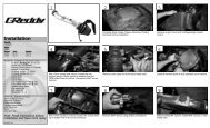
3.<strong>Kit</strong> Install<br />
3-1 OE ventilation Tube No. 1 Modification<br />
Remove the bracket from the ventilation tube in<br />
2-13. Install back to same location.<br />
※ After removing bracket, make sure to de-burr and<br />
paint surface of modified area.<br />
Please use safety glasses and a<br />
mask to prevent injury.<br />
Remove<br />
3-2 <strong>Kit</strong> Lower Alternator Bracket Install<br />
(1) Remove the two lower bolts of the A/C compressor<br />
brackets. Place the provided spacers between the<br />
kit alternator bracket and OE compressor bracket.<br />
※ Replace the two bolts with the provided bolts. Do not<br />
torque these bolts at this time.<br />
〈Parts №11,13,30〉<br />
<strong>Kit</strong> Alternator Bracket<br />
(2) Place the floating nut in the lower alternator bracket.<br />
〈Parts №7,8〉<br />
(3) Install the lower alternator bracket to the engine<br />
block using the provided bolt and attach the<br />
alternator bracket (1) to the lower alternator bracket.<br />
※ Torque bolts in this order:<br />
A/C compressor bracket, lower alternator bracket<br />
(engine block side), alternator bracket.<br />
〈Parts №25,31〉<br />
Floating Nut<br />
<strong>Kit</strong> alternator<br />
bracket<br />
―6―
3-3 <strong>Kit</strong> <strong>Supercharger</strong> assembly<br />
(1) Screw in the provided stud bolts onto the<br />
supercharger outlet flange and apply silicone sealant<br />
to the flange surface. Attach <strong>Kit</strong> intake manifold to<br />
the supercharger.<br />
※ Try to prevent sealant from protruding to the inside<br />
of the manifold.<br />
〈Parts №1,2,27〉<br />
(2) Connect the actuator port to the intake manifold port<br />
using the 6mm hose provided. Secure hose ends<br />
with cable ties.<br />
※ When using a boost gauge, use this pressure source<br />
to monitor intake manifold pressure.<br />
〈Part №16,17〉<br />
3-4 S/C Assy Installation<br />
(1) Remove the OEM stud bolts on the intake side of the<br />
cylinder head and screw in five of the studs provided.<br />
〈Part №28〉<br />
(2) Place the OEM intake manifold gasket between the<br />
intake manifold and head and install manifold<br />
※ When installing the intake manifold, place the radiator<br />
reserve tank on the hood latch.<br />
〈Part №28〉<br />
―7―
3-5 <strong>Kit</strong> Oil Dip Stick Installation<br />
(1) Remove the O-ring from the OE dipstick guide and<br />
place it on the <strong>Kit</strong> dipstick guide.<br />
※ If the O-ring is damaged, please replace with OEM<br />
part.<br />
OE dipstick<br />
guide<br />
<strong>Kit</strong> dipstick<br />
guide<br />
〈Part №9〉<br />
(2) Place the <strong>Kit</strong> dipstick guide in the factory location on<br />
the engine block and attach the bracket to the<br />
supercharger Assy and tighten bolt.<br />
Bracket bolt<br />
3-6 Alternator Installation<br />
(1) Attach the alternator to the lower alternator bracket<br />
installed in step 3-2.<br />
※ Use OEM bolt<br />
Upper alternator bracket<br />
(2) Attach the upper alternator bracket to the alternator<br />
and torque the lower alternator bolt.<br />
※ Use OE bolt on the alternator side of the bracket and<br />
provided bolt for the engine side of bracket.<br />
Torque spec: M8 bolt 29N・m (290kgf・cm)<br />
M10 bolt 58N・m (580kgf・cm)<br />
〈Parts №6,26〉<br />
3-7 <strong>Kit</strong> Tensioner Pulley Installation<br />
Attach the <strong>Kit</strong> tensioner pulley to the lower<br />
alternator bracket with the spacer between the<br />
pulley and bracket. Use the provided bolt to attach<br />
pulley to bracket.<br />
※ Place the pulley so the rim faces the bracket.<br />
※ Use thread lock on the pulley bolt.<br />
〈Parts №4,10,32〉<br />
Rim<br />
―8―
3-8 <strong>Kit</strong> V Ribbed Belt Installation.<br />
Adjust the tensioner pulley toward the front of the<br />
vehicle to adjust belt tension.<br />
VP : Vane Pump Pulley<br />
CK : Crank Pulley<br />
CC : Cooler Compressor<br />
WP : Water Pump Pulley<br />
AL : Alternator Pulley<br />
TP : OE Tensioner Pulley<br />
kit TP : KIT Tenstioner Pulley<br />
SC : <strong>Supercharger</strong> Pulley<br />
〈Part №5〉<br />
3-9 <strong>Kit</strong> Injector Installation<br />
(1) Remove the fuel delivery pipe and fuel injectors<br />
(2) Replace OE injectors with the provided injectors and<br />
install fuel delivery pipe back to original location.<br />
Please check for fuels leaks after kit is<br />
installed to prevent injury or damage from<br />
fire.<br />
<strong>Kit</strong><br />
O-ring<br />
※<br />
※<br />
Use the <strong>Kit</strong> O-ring to seal the top of the injector.<br />
Lubricate O-ring with silicone grease.<br />
Re-use OE bolts, spacer, and injectors insulators.<br />
If the OE Insulator is damaged, please replace.<br />
OE Insulator<br />
※<br />
Install the injector connectors to face toward the<br />
front of the vehicle.<br />
〈Part №21〉<br />
Injector connector direction<br />
―9―
(3) Cut off the OE injector harness connectors and<br />
replace with <strong>Kit</strong> injector harness connectors.<br />
※ Mark or label harness wires to ensure that they are<br />
connected to the proper pin on the injector.<br />
※ Do not connect the injector connector at this time.<br />
Solder procedure<br />
1 Remove sleeve<br />
2 Wrap wires together<br />
3 Solder wires<br />
Double check connections<br />
4 Wrap with electrical tape<br />
3-10 OE Engine Wire Harness<br />
(1) Split the OE Wire harness in this way: A – alternator<br />
B+ wire, B – alternator connector, C – A/C<br />
C<br />
compressor, D – knock sensor, E – crank position<br />
sensor. Wrap the wires with the provided colgate<br />
tubing.<br />
※<br />
Combine the knock sensor and crank position sensor<br />
wire harness into the same colgate tube.<br />
A<br />
※<br />
Cut the colgate tube to the proper lengths and tape<br />
then ends of the tubing with electrical tape.<br />
D,E<br />
B<br />
〈Part №19〉<br />
(2) Connect the sensor harness connectors and<br />
alternator connectors and use cable ties to secure<br />
wires. Connect engine harness to injector<br />
B,C,D,E<br />
connectors.<br />
※<br />
Route the alternator B+ wire in front of the<br />
supercharger and connect to alternator.<br />
〈Parts №17,18〉<br />
A<br />
―10―
3-11 <strong>Kit</strong> Intake Tube Installation<br />
(1) Remove the studs on the OE intake air surge tank<br />
and screw them into the <strong>Kit</strong> intake tube.<br />
〈Part №3〉<br />
(2) Attach the <strong>Kit</strong> intake tube to the supercharger inlet.<br />
At the same time, place the spacer between the <strong>Kit</strong><br />
intake tube bracket and “Thread A” on the picture<br />
and use the M8 x 50mm bolt to secure the bracket.<br />
Secure the other end of the bracket to the engine<br />
block.<br />
※ Use silicone sealant between the supercharger inlet<br />
and intake tube flange. Prevent sealant from<br />
protruding to the inside of the flange.<br />
※ Torque bracket bolts starting from the engine.<br />
〈Parts №12,14,26,29,31〉<br />
Thread A<br />
Bracket spot<br />
on engine<br />
3-12 OE Throttle Body Installation<br />
(1) Place the OE gasket on the intake tube and install<br />
the throttle body, water bypass hose, and electrical<br />
connectors.<br />
※ Re-use OE bolts and nuts. Please confirm that the<br />
throttle body gasket is place properly also.<br />
(2) Install the accelerator control cable.<br />
For vehicles without Auto Cruise Control<br />
Install the accelerator control cable bracket to the<br />
intake tube using the OE bolts and install the<br />
throttle cable to the throttle lever.<br />
Spacer<br />
―11―
For Vehicles With Auto Cruise Control<br />
1 Place the rubber grommets removed in step 2-7<br />
between the cruise control unit and the provided<br />
auto cruise control brackets. Use OE screws to<br />
secure bracket to unit.<br />
〈Part №15〉<br />
Bracket A<br />
Bracket B<br />
2 Use the provided bolts to secure the auto cruise<br />
control unit Assy to the upper radiator support.<br />
Bolt Location<br />
A : Hood latch bracket<br />
B : Air cleaner box<br />
〈Part №24〉<br />
A<br />
B<br />
3 Cut the auto cruise control harness and use the<br />
provided wire to extend the wire.<br />
After soldering wire and wrapping with tape,<br />
wrap with colgate tube and connect harness to<br />
unit.<br />
※ Double check solder for good connection.<br />
※ Make sure you have clearance between the<br />
harness and V ribbed belt.<br />
〈Parts №17,18,19,20〉<br />
Cruise Control<br />
Connector<br />
(3) Connect hoses back to the intake tube and throttle<br />
body.<br />
※ Re-use OE hose bands.<br />
―12―
3-13 <strong>Kit</strong> e-manage Ultimate installation<br />
(1) Remove the ECM box cover and disconnect and<br />
remove connector A, B, and ground from the box.<br />
Remove the electrical tape to all the harness<br />
grommet to move freely. The ECM is on the right side<br />
of the engine bay.<br />
A<br />
B<br />
Ground<br />
Harness Grommet<br />
(2) Locate the A/C line going through the right side of<br />
the firewall. Cut the grommet in the center to allow<br />
the wire harness to pass through the firewall.<br />
(3) Route the wire harness through the firewall.<br />
〈Part №23〉<br />
(4) Route the e-manage harness through the ECM<br />
harness grommet from the smaller end of the<br />
grommet.<br />
(5) Refer to the wire diagram to connect e-manage wires<br />
to the ECM wire harness.<br />
After connections are completed, place all of the<br />
wire connectors back in the ECM box and place the<br />
harness grommet back to its original location.<br />
※ Place the connectors A and B in the ECM box before<br />
connectors C and D.<br />
Remove cover<br />
e-manage harness<br />
Wrap wires and<br />
solder together<br />
Wrap with heat shrink tube and electrical tape<br />
The kit does include connectors for electrical wiring, but it is highly recommended to solder<br />
all wire connections to ensure proper function. Also please confirm that all wires are<br />
wrapped with electrical tape.<br />
―13―
e-manage Ultimate Connector Harness Pin Location<br />
C B A<br />
※ Viewing from wire harness side.<br />
Ultimate<br />
OE ECM<br />
Signal (Color)<br />
Pin №<br />
Pin №<br />
Signal<br />
3 Ignition Input CH4(PL/W) A_11 Ignition Pulse IGT2 To ECM<br />
4 Ignition Input CH2(O/W) A_12 Ignition Pulse IGT3 To ECM<br />
5 Ignition Input CH1(BL/W) A_10 Ignition Pulse IGT1 To ECM<br />
8 Ignition Output CH4(PL/B) A_11 Ignition Pulse IGT2 To Harness<br />
9 Ignition Output CH3(Y/B) A_13 Ignition Pulse IGT4 To Harness<br />
10 Ignition Input CH3(Y/W) A_13 Ignition Pulse IGT4 To ECM<br />
11 Ignition Output CH2(O/B) A_12 Ignition Pulse IGT3 To Harness<br />
12 Ignition Output CH1(BL/B) A_10 Ignition Pulse IGT1 To Harness<br />
14 VTEC Output(Y) ― ―<br />
15 Airflow (Voltage) Input (W) B_11 VG Air Flow Meter To Harness<br />
16 Throttle Input(GY) B_23 VTA Throttle Signal<br />
17 Injector Input CH1(BL/R) A_1 #10 Injector Pulse To ECM<br />
18 Injector Input CH2(O/R) A_2 #20 Injector Pulse To ECM<br />
19 Injector Input CH3(Y/R) A_3 #30 Injector Pulse To ECM<br />
20 Injector Input CH4(PL/R) A_4 #40 Injector Pulse To ECM<br />
22 Airflow (Voltage) Output(G) B_11 VG Air Flow Meter To ECM<br />
23 RPM Signal (BR) C_27 TACH RPM Signal<br />
24 Ground (B) B_17 E1 Ground<br />
25 IG Power (R) D_16 +B Battery Power<br />
30 Injector Ground (B/R) A_21 E01 Injector Ground<br />
33 Crank Angle Signal (GY/W) ― ―<br />
34 Injector Output CH1(BL/GY) A_1 #10 Injector Pulse To Harness<br />
35 Injector Output CH2(O/GY) A_2 #20 Injector Pulse To Harness<br />
36 Injector Output CH3(Y/GY) A_3 #30 Injector Pulse To Harness<br />
39 Camshaft Angle Signal (GY/B) ― ―<br />
40 Vehicle Speed Output (BR/Y) ― ―<br />
41 Vehicle Speed Input (LB/Y) ― ―<br />
42 Injector Output CH4(PL/GY) A_4 #40 Injector Pulse To Harness<br />
―14―
These wire are outlined in the e-manage diagram. These wires will not be used in this kit. Use<br />
electrical tape to cover the ends of the wires to prevent short circuit.<br />
№14 VTEC Output(Y)<br />
№33 Crank Angle Signal(GY/W)<br />
№39 Camshaft Angle Signal(GY/B)<br />
№40 Vehicle Speed Output(BR/Y)<br />
№41 Vehicle Speed Input (LB/Y)<br />
OE ECM Wire Pin Diagram<br />
※Viewing from wire harness side<br />
CONNECTOR A(31P)<br />
CONNECTOR B(24P)<br />
CONNECTOR C(28P)<br />
CONNECTOR D(22P)<br />
e-manage Ultimate Wire Diagram<br />
Connector<br />
34(B/GY)<br />
17(B/R)<br />
Male Female<br />
35(O/GY)<br />
18(O/R)<br />
Splice<br />
30(B/R)<br />
36(Y/GY)<br />
19(Y/R)<br />
42(PL/GY)<br />
20(PL/R)<br />
15(W)<br />
22(G)<br />
10(Y/W)<br />
9(Y/W)<br />
4(O/W)<br />
11(O/B)<br />
16(GY)<br />
24(B)<br />
23(BR)<br />
25(R)<br />
3(PL/W)<br />
8(PL/B)<br />
5(BL/W)<br />
12(BL/B)<br />
Color Code: W-White, G-Green, B-Black, BL-Blue, BR-Brown, R-Red, GY-Grey, PL-Purple<br />
Y-Yellow, O-Orange, LB-Light, PI-Pink<br />
―15―
(6) Route the e-manage ultimate wire harness safely though the engine bay and use cable ties to secure the<br />
harness and prevent it from moving. Place the A/C line grommet in its original location.<br />
※ Use cable ties to secure the harness to the accelerator control cable secure areas. 〈Part №18〉<br />
(7) Adjust the dipswitches on the e-manage Ultimate unit. Secure the unit and plug in the harness<br />
connectors.<br />
※ Refer to the diagram below for dipswitch instructions.<br />
It is important that you adjust these switches properly.<br />
Engine damage may be caused if not set properly<br />
※<br />
※<br />
Secure the e-manage unit in an area free from moisture, dust, sunlight, and direct heat from<br />
the heater vents.<br />
Please try to avoid placing the e-manage unit under the carpet or floor mats.<br />
○ Front Panel Dip Switch Settings<br />
Application<br />
Switch Setting<br />
・Use with OE Air Cleaner Box<br />
・Use with AIRINX Filter <strong>Kit</strong><br />
・Factory setting<br />
※1,3-ON<br />
※1,2,3,4-ON<br />
3-14 OE Air Cleaner Installation<br />
Install the air cleaner case, air cleaner hose No.1, engine bay ECM outlet duct, and upper radiator<br />
support seal.<br />
※ If installing AIRINX Air Filter Set, refer to AIRINX instruction manual.<br />
3-15 OE Cylinder Head Cover Modification<br />
Cut the highlighted portion of the cylinder head<br />
cover No.2 in the picture on the right.<br />
Re-use the OE bolts.<br />
Please use safety glasses and a<br />
mask to prevent injury.<br />
―16―
3-16 Starting the Engine<br />
(1) Install the radiator reserve tank to its original location and fill with coolant.<br />
Bleed the air from the cooling system after starting engine.<br />
(2) Install the battery tray and batter. Connect the B+ terminal of the battery.<br />
(3) Inspect all harness connectors and wire connections and connect the B – terminal of the batter.<br />
(4) Start the engine and inspect fuel lines and injectors for any fuel leaks.<br />
※ Check the e-manage unit to see if the active light is green. If it is not, please check the e-manage<br />
wire connections to the OE ECM.<br />
※ Check to see if the e-manage unit has error codes (active light blinks red).<br />
(5) At idling, inspect for water or vacuum leaks.<br />
(6) Install the RH engine under cover.<br />
(7) Install the upper front fender apron seal and cylinder head cover No.2.<br />
This completes the<br />
<strong>Supercharger</strong> <strong>Kit</strong> installation<br />
IMPORTANT<br />
o It is very important that you monitor the boost pressure, and make sure not to over boost.<br />
Over boosting can cause engine damage.<br />
o <strong>GReddy</strong> Performance Products, Inc. is not responsible for any engine damage caused by over<br />
boosting (increased boost), modification to the kit, and/or misuse of the product. NO<br />
WARRANTY is offered.<br />
o Due to lack of control over proper installation and use of this product,<br />
NO WARRANTY is offered for this kit.<br />
―17―
Front Fender Apron & Dash Panel
Cylinder Head
Suspension Cross Member and Under Cover
Switch and Relay
Air Cleaner
Fuel Injection System
Ventilation Hose
Cylinder Block
Manifold