Diagnose Repair & Replace.pdf
Diagnose Repair & Replace.pdf
Diagnose Repair & Replace.pdf

Create successful ePaper yourself
Turn your PDF publications into a flip-book with our unique Google optimized e-Paper software.
Cybex Arc Trainer 610A Service Manual<br />
4 - Service<br />
Warnings/Cautions<br />
All warnings and cautions listed in this chapter are as follows:<br />
! WARNING: All maintenance activities shall be performed by qualified personnel.<br />
Failure to do so could result in serious injury.<br />
! WARNING: Disconnect the power cord before beginning this procedure. Keep wet items<br />
away from inside parts of the unit. Electrical shock could occur even if the unit is<br />
unplugged.<br />
! WARNING: Flywheel may be hot. Wait until it cools before servicing.<br />
! CAUTION: Do not pinch your fingers between the belt and pulley during this procedure.<br />
! WARNING: Failure to release the drive belt tension may cause personal injury and may<br />
damage the unit.<br />
! WARNING: Do not touch components on the lower board. A charge can remain after<br />
unplugging the power cord and turning off the unit.<br />
! CAUTION: Pulley on eddy current brake is sharp. Wear work gloves to protect your hands.<br />
Service<br />
Page 4-1
time<br />
Cybex Arc Trainer 610A Service Manual<br />
! WARNING: All maintenance activities shall be performed by qualified personnel.<br />
Failure to do so could result in serious injury.<br />
For any service related concerns, call Cybex<br />
Customer Service at 800-766-3211 (for Cybex<br />
customers living within the USA). For customers<br />
living outside the USA, call 508-533-4300 or fax<br />
508-533-5183.<br />
NOTE: Read and understand each procedure<br />
thoroughly before servicing. Unless otherwise noted<br />
“right” and “left” denote user orientation for all<br />
procedures.<br />
Test Mode<br />
To enter Test Mode press and hold down the<br />
Pause/end key on the display while turning the<br />
power switch to the on (I) position. When all keys<br />
are released “ARC” and the software revision “x.xx” are shown on the display. To exit Test Mode press<br />
Pause/end.<br />
Stuck Key List<br />
It Test Mode occurs without holding any keys, a key may be stuck closed or Error 7 may have<br />
occurred. You may need to replace the upper and/or lower display overlay. See Figure 1. If “KEY#” is<br />
displayed you can determine which key is stuck closed by referring to the number list below.<br />
Upper<br />
Overlay<br />
manual<br />
hill<br />
interval<br />
weight<br />
loss<br />
scan<br />
enter<br />
level<br />
strides<br />
minute<br />
weight<br />
Cybex International, Inc. Medway, MA USA (508) 533-4300 www.Cybexinternational.com<br />
Lower<br />
Overlay<br />
resistance<br />
Figure 1<br />
Service<br />
Page 4-2<br />
1 Mets 9 Incline Down 17 Incline Up 25 Pause/End<br />
2 Auxiliary 10 Resistance Down 18 Resistance Up 26 Quick Start<br />
3 Channel Up 11 Channel Down 19 Volume Down 27 Volume Up<br />
4 Scan 12 Strength 20 Center Up 28 Hill Interval<br />
5 Watts 13 Cal/Hr 21 Cal 29 Dist<br />
6 Cardio 14 Interval 22 Weight Loss 30 Manual<br />
7 Level 15 Time 23 Weight 32 Strides/Minute<br />
8 Enter 16 Center Down 24 Heart
Cybex Arc Trainer 610A Service Manual<br />
LED Functions<br />
LEDs are used to indicate the status of many of the unit inputs. After entering Test Mode refer to the<br />
following list to check that these LEDs are functioning properly:<br />
Heart LED - Blinks on blue with every signal from the contact heart rate receiver and red for wireless<br />
signals (Polar).<br />
Weight LED - Blinks on when CSAFE data is being received.<br />
Level LED - Blinks on when CSAFE data is being transmitted.<br />
Lower Left Window - The numbers indicate actual elevation. The decimal point before the numbers<br />
shows the activation of the level 3 position switch in the elevation motor (on above level 3). If dashes<br />
are shown in the display, the unit is either above or below the level 3 position switch, requiring it to be<br />
manually run through the switch to begin indicating actual elevation.<br />
Lower Right Window - The numbers indicate resistance (0-100). The right most decimal point<br />
indicates the pulses from the speed sensor.<br />
Key Functions<br />
While in Test Mode press the following keys for desired information:<br />
Hill Interval key - Lights all of the LEDs for a short period of time.<br />
Weight Loss key - Lights only the columns.<br />
Strength key - Lights only the rows.<br />
Incline - Run elevation motor up.<br />
Incline - Run elevation motor down.<br />
Resistance + (plus) - Run resistance up.<br />
Resistance - (minus) - Run resistance down.<br />
Distance - Press once for odometer information (DST) to appear in the speed window.<br />
Press again for hour meter information (HRS) to appear in the speed window.<br />
Press three times for number of starts information (USES) to appear in the speed window.<br />
Press four times for number of positions the elevation (ELV) has ever moved. Example: if a user runs<br />
the elevation from 2 to 3, 1 position is added to this number.<br />
Strides Per Minute - Displays and cycles through error log. Up to 10 errors can be stored.<br />
Scan - Clears error log when pressed twice while in error log mode.<br />
Mets - Displays the torque in ft-lbs, (relative to LOAD).<br />
Calories - Displays brake pulse width (PWM) value (the value of brake load in A/D counts). The number<br />
range is relative to brake current and goes from 0-200.<br />
Enter - Required to save setup values.<br />
Service<br />
Page 4-3
Cybex Arc Trainer 610A Service Manual<br />
Error Codes<br />
Error codes notify you of a problem condition and are displayed on the center of the console. These<br />
codes can also help to indicate the part of the unit most likely to be causing the problem. Errors that<br />
present a hazard to the user provide a measure of safety by causing a one second beep, stopping the<br />
unit and locking out operation of the unit.<br />
A log of errors can be viewed and cleared. Up to 10 errors can be stored.<br />
To enter Test Mode: Press and hold down any key on the display while turning the power switch to<br />
the on (I) position.<br />
To view the Error Log: Press the Strides Per Minute key to display and cycle through error log; Press<br />
again to cycle to the next stored error.<br />
To clear the Error Log: Press the Scan key twice.<br />
To exit Test Mode: Press the Stop key.<br />
NOTE: A processor upset can cause a bAd#. See F then G.<br />
Error Description<br />
bAd0 Bad check sum. See F then E.<br />
bAd2 Internal RAM error. See F then E.<br />
bAd3 Watchdog timeout. See F then E.<br />
Err3 Speed sense lost. See A and B.<br />
Err5 No index switch sense within timed limits. This is declared when the timed elevation<br />
reaches 0% without tripping the index. See D and A.<br />
Err7 EEPROM error (memory lost, loads new defaults, enters Test Mode). See E.<br />
ErrE Index switch always on (or switch disconnected or wired backwards). This means that timed<br />
elevation has gone up 3 positions and the index is still sensed. See D.<br />
Action<br />
A<br />
B<br />
C<br />
D<br />
E<br />
F<br />
Check the lower board<br />
Check the brake<br />
Check the speed sensor and speed sensor disc<br />
Check the elevation motor<br />
<strong>Replace</strong> the display board is problem persists<br />
Turn the power switch to the off (O) position and back on (I)<br />
Service<br />
Page 4-4
Cybex Arc Trainer 610A Service Manual<br />
Speed Sensor Adjustment<br />
Tools Required<br />
• Phillips head screwdriver<br />
! WARNING: Disconnect the power cord before beginning this procedure. Keep wet items away<br />
from inside parts of the unit. Electrical shock could occur even if the unit is<br />
unplugged.<br />
1. Disconnect the external power source.<br />
A. Turn the main power switch above the power<br />
inlet to the off (O) position.<br />
Access<br />
Cover<br />
B. Unplug the power cord from the power outlet.<br />
2. Remove the access cover.<br />
A. Using a Phillips head screwdriver, remove the<br />
four screws securing the access cover. See<br />
Figure 2.<br />
B. Remove the access cover.<br />
3. Visually inspect the target disk on the lower<br />
pulley.<br />
A. Turn the lower pulley slowly and look for dirt,<br />
scratches or other damage on the target disk.<br />
See Figure 3. NOTE: If the target disk or<br />
speed sensor is dusty use a soft dry cloth to<br />
wipe off the dust. A dirty, scratched or<br />
damaged disk may cause Error 3 to occur.<br />
Figure 2<br />
Screws (4)<br />
4. Measure the speed sensor gap.<br />
A. Measure the gap between the speed sensor<br />
and the lower pulley. It should measure 3/16”<br />
(.48 cm) and should be parallel to the lower<br />
pulley. See Figure 3.<br />
Target Disk<br />
on Lower<br />
Pulley<br />
Gap<br />
Speed<br />
Sensor<br />
Screw<br />
Figure 3<br />
Service<br />
Page 4-5
Cybex Arc Trainer 610A Service Manual<br />
5. Adjust the speed sensor gap (if needed).<br />
A. Using a Phillips head screwdriver, loosen the screw securing the speed sensor in place. See<br />
Figure 3. NOTE: Gently bend the side cover to get at the speed sensor screw.<br />
B. Adjust the gap between the speed sensor and the lower pulley to 3/16” (.48 cm) and tighten<br />
the screw. See Figure 3.<br />
6. Test for speed errors.<br />
A. Connect the power cord to a power outlet.<br />
B. Enter Test Mode.<br />
! WARNING: Flywheel may be hot. Wait until it cools before servicing.<br />
! CAUTION: Do not pinch your fingers between the belt and pulley during this procedure.<br />
C. Slowly move the flywheel with your hand and check the speed LED on the lower board. It<br />
should blink as the target disk passes the sensor.<br />
D. Mount the unit and begin striding at a steady pace.<br />
E. While striding, take note of the speed that is displayed in the strides-per-minute display. This<br />
number should increase as you stride faster. If the number fluctuates greatly then your speed<br />
sensor gap may need to be readjusted or replaced.<br />
F. Press Stop and turn the power switch to the off (O) position.<br />
7. Attach the access cover.<br />
A. While being sure not to pinch any cables, hold the access cover in place. See Figure 2.<br />
B. Using a Phillips head screwdriver, tighten the four screws securing the access cover.<br />
Service<br />
Page 4-6
Cybex Arc Trainer 610A Service Manual<br />
Drive Belts<br />
NOTE: This procedure will cover the primary and secondary drive belts.<br />
Tools Required<br />
• Phillips head screwdriver<br />
• 3/16” Allen wrench<br />
• 2 Cloths<br />
• 3/8” Nutdriver or socket wrench<br />
• 7/16” Socket wrench<br />
• 1/2” Socket wrench (only if belt tension needs to be reset)<br />
• 1/2” Open end wrench (only if belt tension needs to be reset)<br />
• 3/8” Square-hole torque wrench (only if belt tension needs to be reset)<br />
! WARNING: Disconnect the power cord before beginning this procedure. Keep wet items away<br />
from inside parts of the unit. Electrical shock could occur even if the unit is<br />
unplugged.<br />
1. Elevate the unit and disconnect the power source.<br />
A. Plug the power cord into the power outlet.<br />
B. Enter Test Mode.<br />
C. Elevate the unit to a minimum of level 7 incline.<br />
D. While the unit is elevated, turn the main power switch to the off (O) position and unplug the<br />
power cord from the power outlet.<br />
2. Remove the access cover.<br />
A. Using a Phillips head screwdriver, remove the four screws securing the access cover. See<br />
Figure 2.<br />
B. Remove the access cover.<br />
! WARNING: Flywheel may be hot. Wait until it cools before<br />
servicing.<br />
3. Detach the connecting rods.<br />
A. Using a 3/16” Allen wrench, remove the Cap, SHCS<br />
and spacer securing the linkage rod. See Figure 4.<br />
NOTE: Detach only the ends where the rods connect<br />
to the crank.<br />
Connecting<br />
Rod<br />
Washer<br />
Cap<br />
SHCS<br />
B. Lay the linkage rod down on the frame.<br />
NOTE: Place a cloth in between the<br />
linkage rod and the frame to prevent<br />
scratches.<br />
Cloth on<br />
the Frame<br />
Figure 4<br />
Service<br />
Page 4-7
Cybex Arc Trainer 610A Service Manual<br />
4. Remove the side covers.<br />
Gasket<br />
Side Cover<br />
A. Remove the six screws and six washers<br />
securing each side cover in place. See<br />
Figure 5.<br />
B. Remove both side covers. NOTE: The<br />
gasket will come off with one of the side<br />
covers. See Figure 5.<br />
Screw (6)<br />
Washer (6)<br />
5. Remove the crank covers.<br />
A. Using a Phillips head screwdriver, remove<br />
the three screws securing each crank<br />
cover in place. See Figure 6.<br />
B. Remove both crank covers.<br />
! WARNING: Failure to release the drive belt<br />
tension may cause personal injury<br />
and may damage the unit.<br />
6. Remove the lower pivot assembly.<br />
A. Using a 7/16” socket wrench, remove<br />
the two screws, two lock washers and<br />
two flat washers from the lower pivot<br />
shaft. See Figure 7. NOTE: The tension is<br />
now released. The primary belt can be<br />
replaced without loosening the idler pulley.<br />
NOTE: If you are not replacing the secondary<br />
belt, leave the lower pivot assembly loose<br />
in its place, skip steps 6B-8E and<br />
continue with step 9.<br />
B. Remove the lower pivot assembly out<br />
of the secondary belt and from the frame.<br />
See Figure 8.<br />
7. Remove the secondary belt (if applicable).<br />
A. Slide the secondary drive belt off the unit<br />
and discard it.<br />
Figure 5<br />
Figure 6<br />
Screw<br />
Lock<br />
Washer<br />
Flat<br />
Washer<br />
Crank Cover<br />
Screw (3)<br />
Lower Pivot<br />
Shaft<br />
Figure 7<br />
Service<br />
Page 4-8
Cybex Arc Trainer 610A Service Manual<br />
NOTE: If you are not replacing the primary belt skip to<br />
step 14.<br />
! WARNING: Do not touch components on the lower<br />
board. A charge can remain after<br />
unplugging the power cord and turning off<br />
the unit.<br />
Secondary Drive Belt<br />
(Removed in Step 7)<br />
Lower<br />
Pulley<br />
8. Remove the lower board assembly (if applicable).<br />
A. Pull out on the lower board shield. See Figure 9.<br />
NOTE: It will snap out.<br />
B. Disconnect the elevation motor cable from the<br />
lower board. See Figure 10.<br />
C. Using a 3/8” nutdriver, remove the nut, washer<br />
and ground wire from the stud above the<br />
lower board. See Figure 10.<br />
D. Using a Phillips head screwdriver,<br />
remove the top two screws from the<br />
lower board assembly and loosen the<br />
bottom two screws. See Figure 11.<br />
E. Slide the lower board assembly to the<br />
left and off the two screws, then gently<br />
let it suspend by the cables.<br />
Spacer (2)<br />
Lower Board<br />
Shield<br />
Lower Pivot Assembly<br />
Figure 8<br />
Nut<br />
Ground<br />
Wire<br />
Washer<br />
Stud<br />
9. Remove the crank shaft assembly (if<br />
applicable).<br />
A. Using a 9/16” socket wrench and a 9/16”<br />
open end wrench, remove the two bolts,<br />
four flat washers and two nuts from each<br />
of the top pillow blocks. See Figure 12.<br />
Figure 9<br />
Elevation<br />
Cable<br />
Figure 10<br />
Remove Top Screws<br />
Lower Board<br />
Assembly<br />
Figure 11<br />
Loosen Bottom<br />
Screws<br />
Service<br />
Page 4-9
Cybex Arc Trainer 610A Service Manual<br />
Pillow Block (2)<br />
NOTE: Nuts (4) and<br />
flat washers (4) are<br />
behind the pillow<br />
blocks.<br />
Pin<br />
Bolt (4)<br />
Pin<br />
Flat Washer (8)<br />
Figure 12<br />
B. Remove the crank shaft assembly<br />
along with the primary belt, pillow blocks<br />
and crank arms out of the unit. NOTE:<br />
You may need to wiggle the assembly out.<br />
There is a pin in each pillow block. Be<br />
sure not to lose them. See Figure 13.<br />
10. Remove the primary belt (if applicable).<br />
Primary<br />
Drive Belt<br />
Crank Shaft Assembly<br />
Washer (8)<br />
Pin (2) Nut (4)<br />
A. Slide the primary drive belt off the<br />
upper pulley and discard it. See<br />
Figure 13.<br />
11. Attach the primary belt (if applicable).<br />
A. Slide the new primary drive belt on<br />
the upper pulley. See Figure 13.<br />
Screw (4)<br />
Upper<br />
Pulley<br />
Pillow<br />
Block (2)<br />
Crank<br />
Arm (2)<br />
B. Confirm that the primary drive belt is<br />
straight and centered on the upper<br />
pulley.<br />
Figure 13<br />
12. Attach the crank shaft assembly (if applicable).<br />
A. Confirm that a pin (removed in step 9B) protrudes about 1/4” out of the back of each pillow<br />
block. NOTE: The pins will slide into the frame in the next step. See Figures 12 and 13.<br />
B. Lift the assembly and slide the pins into the holes on the frame. NOTE: The pins should be<br />
flush with the front of the pillow blocks. You may need to tap them in.<br />
C. Using a 9/16” socket wrench and a 9/16” open end wrench, secure the two bolts, four flat<br />
washers and two nuts (removed in step 9A) to each pillow block. See Figure 12.<br />
Service<br />
Page 4-10
Cybex Arc Trainer 610A Service Manual<br />
! CAUTION: Do not pinch your fingers between the belt and pulley during this procedure.<br />
13. Attach the lower board assembly.<br />
A. Slide the lower board assembly over the two bottom screws and to the right.<br />
B. Using a Phillips head screwdriver, attach the top two screws and tighten the two bottom<br />
screws securing the lower board assembly in place.<br />
C. Place the washer on the stud then follow it with the ground wire terminal. Use a 3/8”<br />
nutdriver to secure the nut over the terminal. See Figure 10.<br />
D. Connect the elevation motor cable into the lower board.<br />
E. Place the shield into position and push in (the shield will snap in). See Figure 9.<br />
14. Position the secondary drive belt.<br />
A. Slide the new secondary drive belt into place on the frame.<br />
15. Secure the lower pivot assembly.<br />
A. Slide the lower pivot assembly through both drive belts and into place on the frame.<br />
B. Confirm that the secondary drive belt is straight and centered on the lower pulley. See<br />
Figure 12.<br />
C. Confirm that the two spacers are still in place under the lower pivot shaft.<br />
D. Using a 7/16” socket wrench, tighten the two screws, two lock washers and two flat washers<br />
securing the lower pivot assembly in place.<br />
16. Check the tension of the primary drive belt.<br />
A. Press on the primary belt with your hand. You should not feel any “give” in the primary belt. If<br />
the belt “gives”, follow step 17 through 18. Otherwise, skip to step 19. NOTE: The secondary<br />
belt is self-tensioning.<br />
17. Release the tension of the primary drive belt.<br />
A. Using a 1/2” socket wrench, loosen the bottom screw on the idler pulley. See Figure 14.<br />
B. Using a 1/2” socket wrench, loosen the top screw on the idler pulley See Figure 14.<br />
Service<br />
Page 4-11
Cybex Arc Trainer 610A Service Manual<br />
NOTE: Do not adjust<br />
the idler pulley unless<br />
it is obvious that your<br />
belt is not tensioned<br />
properly.<br />
This Side of<br />
Bracket<br />
Idler<br />
Pulley<br />
This Side of<br />
Bracket<br />
Top Screw<br />
Bottom Screw<br />
Figure 14<br />
18. Torque the primary belt (if applicable).<br />
A. Using a 3/8” square-hole torque wrench, pull up until the idler wheel rocks against the brake<br />
and is torqued to 75 ft-lbs. NOTE: Continue holding the torque wrench at 75 ft-lbs during the<br />
next step.<br />
B. While holding the torque wrench at 75 ft-lbs, use a 1/2” socket wrench to tighten the top screw<br />
on the idler pulley. See Figure 14.<br />
C. Using a 1/2” socket wrench, tighten the bottom screw on the idler pulley. See Figure 14.<br />
19. Attach the crank covers.<br />
A. Place each crank cover in position.<br />
B. Using a Phillips head screwdriver, attach the three screws securing each crank cover in place.<br />
See Figure 6.<br />
20. Attach the side covers.<br />
A. Place each side cover in position in the rubber gasket.<br />
B. Using a Phillips head screwdriver, tighten the six screws and six washers securing each side<br />
cover. See Figure 5.<br />
21. Secure the connecting rods.<br />
A. Using a 3/16” Allen wrench, attach the screw securing each connecting rod to each crank.<br />
See Figure 4.<br />
22. Attach the access cover.<br />
Service<br />
Page 4-12<br />
A. While being sure not to pinch any cables, hold the access cover in place. See Figure 2.
Cybex Arc Trainer 610A Service Manual<br />
B. Using a Phillips head screwdriver, tighten the four screws securing the access cover.<br />
See Figure 2.<br />
Eddy Current Brake<br />
Tools Required<br />
• Phillips head screwdriver<br />
• 3/16” Allen wrench<br />
• 7/16” Socket wrench<br />
• Work Gloves<br />
! WARNING: Disconnect the power cord before beginning this procedure. Keep wet items away<br />
from inside parts of the unit. Electrical shock could occur even if the unit is<br />
unplugged.<br />
1. Elevate the unit and disconnect the power source.<br />
A. Plug the power cord into the power outlet.<br />
B. Enter Test Mode.<br />
C. Elevate the unit to a minimum of level 7 incline.<br />
D. While the unit is elevated, turn the main power switch to the off (O) position and unplug the<br />
power cord from the power outlet.<br />
2. Remove the access cover.<br />
A. Using a Phillips head screwdriver, remove the four screws securing the access cover. See<br />
Figure 2.<br />
B. Remove the access cover.<br />
! WARNING: Flywheel may be hot. Wait until it cools before servicing.<br />
3. Detach the connecting rods.<br />
A. Using a 3/16” Allen wrench, remove the screw securing each connecting rod to each crank.<br />
See Figure 4.<br />
B. Place a cloth on the frame where the connecting rod will rest.<br />
C. Rest the rod on the cloth to prevent scratches. See Figure 4.<br />
4. Loosen the left side cover<br />
A. Using a Phillips head screwdriver, remove the six screws and six washers securing each side<br />
cover in place. See Figure 5.<br />
B. Remove both side covers. NOTE: The gasket will come off with one of the side covers.<br />
See Figure 5.<br />
Service<br />
Page 4-13
Cybex Arc Trainer 610A Service Manual<br />
5. Remove the left crank cover.<br />
A. Using a Phillips head screwdriver, remove the<br />
three screws securing the left crank cover in<br />
place. See Figure 6.<br />
B. Remove the left crank cover.<br />
Loosen Screws<br />
! WARNING: Failure to release the drive belt tension<br />
may cause personal injury and may<br />
damage the unit.<br />
6. Release the drive belt tension.<br />
Lower Pivot<br />
Shaft<br />
A. Using a 7/16” socket wrench, loosen the two<br />
screws on the lower pivot shaft until the screws<br />
Figure 15<br />
are raised 1/2” (1.25 cm) above the screws on the lower pivot shaft. See Figure 15. NOTE: The<br />
drive belt tension is now released.<br />
! WARNING: Do not touch components on the lower board. A charge can remain after<br />
unplugging the power cord and turning off the unit.<br />
7. Disconnect the brake cables.<br />
A. Pull out on the lower board shield. See Figure 9. NOTE: It will snap out.<br />
B. Locate the two brake cables on the lower board that are labeled J1 and J2.<br />
C. Disconnect the two brake cables from the lower board.<br />
! CAUTION: Pulley on eddy current brake is sharp. Wear work gloves to protect your hands.<br />
8. Remove the eddy current brake.<br />
A. Wear work gloves whenever handling the eddy current brake. The pulley is sharp.<br />
See Figure 16.<br />
Screw (4)<br />
Orientation of<br />
the Cable<br />
Non-Threaded Hole (4)<br />
Pulley<br />
Figure 16<br />
Pins on<br />
Brake<br />
Mount Flywheel<br />
Bracket<br />
Secondary Drive<br />
Belt<br />
Threaded Hole (4)<br />
Screw (4)<br />
Service<br />
Page 4-14
Cybex Arc Trainer 610A Service Manual<br />
B. When the flywheel is cool, remove the secondary belt from the eddy current brake.<br />
C. Using a 3/16” Allen wrench, first remove the two bottom screws securing the eddy current<br />
brake in place. See Figure 16.<br />
D. Support the brake with your hand while removing the two top screws so that it does not fall.<br />
E. Remove the eddy current brake from the unit. NOTE: Cybex may want the old parts for<br />
evaluation. Call Cybex Customer Service to get an RMA number.<br />
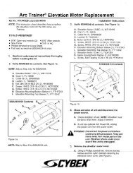
9. Attach the new eddy current brake.<br />
A. Locate the holes on the eddy current brake. Notice that there are four threaded holes and four<br />
non-threaded holes. See Figure 16.<br />
B. Locate the two pins on the brake mount bracket. See Figure 16.<br />
C. Orient the brake with the cable away from the unit. See Figure 16.<br />
D. Slide the brake pulley into the secondary drive belt.<br />
E. Place the two pins in any of the non-threaded holes on the bracket. NOTE: Do not place the<br />
pins in threaded holes.<br />
F. Confirm that the brake is flat against the bracket and that the drive belt is straight on the pulley.<br />
NOTE: Continue to support the brake during the next step.<br />
G. Using a 3/16” Allen wrench, first tighten the two top screws securing the eddy current brake.<br />
See Figure 16.<br />
H. Tighten the two bottom screws securing the eddy current brake.<br />
10. Connect the brake cables.<br />
A. Locate the J1 and J2 fast-ons on the lower board.<br />
B. Connect the brake cables to the lower board at J1 and J2. NOTE: It does not matter which<br />
brake cable connects to J1 and J2.<br />
C. Place the lower board shield in position and snap it in.<br />
11. Tension the drive belt.<br />
A. Confirm that the secondary drive belt is straight and centered on the lower pulley. See<br />
Figure 12.<br />
B. Confirm that the two spacers are still in place under the lower pivot shaft.<br />
C. Using a 7/16” socket wrench, tighten the two screws on the lower pivot shaft.<br />
Service<br />
Page 4-15
Cybex Arc Trainer 610A Service Manual<br />
! CAUTION: Do not pinch your fingers between the belt and pulley during this procedure.<br />
D. Use your hand to slowly turn the flywheel and ensure that the belt is on straight.<br />
12. Attach the left crank cover.<br />
A. Place the crank cover in position.<br />
B. Using a Phillips head screwdriver, attach the three screws removed in step 5A. See Figure 6.<br />
13. Secure the left side cover.<br />
A. Using a Phillips head screwdriver, attach the six screws and six washers removed in step 4A.<br />
14. Attach the left connecting rod.<br />
A. Place the left connecting rod in position.<br />
B. Using a 3/16” Allen wrench, attach the screw removed in step 3A. See Figure 4.<br />
15. Attach the access cover.<br />
A. While being sure not to pinch any cables, place the access cover in position.<br />
B. Using a Phillips head screwdriver, attach the four screws removed in step 2A. See Figure 2.<br />
16. Test the unit for proper operation.<br />
A. Connect the power cord into the power outlet.<br />
B. Turn the main power switch above the power inlet to the on (I) position.<br />
C. Operate the unit to verify proper operation.<br />
Elevation Motor<br />
Tools Required<br />
• Phillips head screwdriver<br />
• 3/16” Allen wrench<br />
• 7/16” Socket wrench<br />
• 3/8” Nutdriver or socket wrench<br />
• 9/16” Open end wrench<br />
• 9/16” Socket wrench<br />
! WARNING: Disconnect the power cord before beginning this procedure. Keep wet<br />
items away from inside parts of the unit. Electrical shock could occur even<br />
if the unit is unplugged.<br />
Service<br />
Page 4-16
Cybex Arc Trainer 610A Service Manual<br />
1. Elevate the unit and disconnect the power source.<br />
A. Plug the power cord into the power outlet.<br />
B. Enter Test Mode.<br />
C. Elevate the unit to a minimum of level 7 incline.<br />
D. While the unit is elevated, turn the main power switch to the off (O) position and unplug the<br />
power cord from the power outlet.<br />
2. Remove the access cover.<br />
A. Using a Phillips head screwdriver, remove the four screws securing the access cover.<br />
See Figure 2.<br />
B. Remove the access cover.<br />
! WARNING: Flywheel may be hot. Wait until it cools before servicing.<br />
3. Detach the connecting rods.<br />
A. Using a 3/16” Allen wrench, remove the screw securing each connecting rod to each crank.<br />
See Figure 4. NOTE: Detach only the ends where the rods connect to the crank.<br />
B. Place a cloth on the frame where each connecting rod will rest.<br />
C. Rest each rod on a cloth to prevent scratches. See Figure 4.<br />
4. Remove the side covers.<br />
A. Using a Phillips head screwdriver, remove the six screws and six washers securing each side<br />
cover in place. See Figure 5.<br />
B. Remove both side covers. NOTE: The gasket will come off with one of the side covers.<br />
See Figure 5.<br />
5. Remove the center cover.<br />
A. Using a Phillips head screwdriver, remove the two screws securing the center cover in place.<br />
B. Remove the center cover.<br />
! WARNING: Do not touch components on the lower board. A charge can remain after<br />
unplugging the power cord and turning off the unit.<br />
6. Disconnect the elevation cable.<br />
A. Pull out on the lower board shield. NOTE: It will snap out.<br />
B. Disconnect the elevation cable from the lower board and slide it out of its slot on the frame.<br />
Service<br />
Page 4-17
7. Remove the elevation motor.<br />
Cybex Arc Trainer 610A Service Manual<br />
A. Place your body next to the front<br />
end assembly to prevent it from<br />
pivoting and falling to the floor<br />
during the next step.<br />
Nut<br />
Spacer<br />
Top<br />
Bolt<br />
B. Using a 9/16” open end wrench<br />
and a 9/16” socket wrench,<br />
remove the top bolt and nut<br />
securing the elevation motor in<br />
place. See Figure 17. NOTE: Do<br />
not lose the spacer between the<br />
bolt and nut.<br />
11.37”<br />
(28.9 cm)<br />
C. Pivot the front end assembly back<br />
and lean it against the frame<br />
(not the floor).<br />
D. Using a 9/16” open end wrench<br />
and a 9/16” socket wrench,<br />
remove the bottom bolt and nut<br />
securing the elevation motor in<br />
place. NOTE: Do not lose the<br />
spacer between the bolt and nut.<br />
E. Remove the elevation motor.<br />
NOTE: Cybex may want the old<br />
Figure 17<br />
parts for evaluation. Call Cybex<br />
Customer Service to get an RMA number.<br />
8. Calibrate the elevation motor.<br />
Bottom<br />
Bolt<br />
Nut<br />
Tube<br />
Spacer<br />
A. Connect the elevation motor to the lower board and temporarily connect the power. NOTE: The<br />
switch should automatically adjust to the level 3 position (starting level) before adjusting the<br />
tube nut.<br />
B. Turn the tube with your fingers until it measures 11.37” (28.9 cm) from the center of the top<br />
hole to the center of the bottom hole. See Figure 17.<br />
C. Turn the main power switch above the power inlet to the off (O) position and disconnect the<br />
power cord.<br />
D. Disconnect the elevation motor cable from the lower board and set the motor aside until step<br />
10A.<br />
9. Attach the elevation motor.<br />
A. Confirm that the two spacers (from step 7B and 7D) are in place.<br />
B. Pivot the front end assembly back into the position it was before step 7C.<br />
C. Place the new elevation motor in position and slide both bolts into the slots before tightening.<br />
See Figure 17. NOTE: The top bolt goes from the left to the right, but the bottom bolt can go<br />
either way.<br />
Service<br />
Page 4-18
Cybex Arc Trainer 610A Service Manual<br />
D. Using a 9/16” open end wrench and a 9/16” socket wrench, tighten a nut on each bolt.<br />
10. Connect the elevation cable.<br />
A. Connect the elevation cable to the lower board and place it in the slot mentioned in step 6B.<br />
B. Place the lower board shield in position and snap it in.<br />
11. Secure the center cover.<br />
A. Place the center cover in position.<br />
B. Using a Phillips head screwdriver, attach the two screws removed in step 5A.<br />
12. Secure the side covers.<br />
A. Place the two side covers and the gasket in position.<br />
B. Using a Phillips head screwdriver, attach each side cover with the six screws and six washers<br />
removed in step 4A. NOTE: You will have to elevate the unit to level 7 to attach the bottom two<br />
screws as discussed in step 1.<br />
13. Attach the connecting rods.<br />
A. Place each connecting rod in position.<br />
B. Using a 3/16” Allen wrench, attach each connecting rod with a screw removed in step 3A. See<br />
Figure 4.<br />
14. Attach the access cover.<br />
A. While being sure not to pinch any cables, place the access cover in position.<br />
B. Using a Phillips head screwdriver, attach the four screws removed in step 2A. See Figure 2.<br />
15. Test the unit for proper operation.<br />
A. Connect the power cord into the power outlet.<br />
B. Turn the main power switch above the power inlet to the on (I) position.<br />
C. Operate the unit at all levels to verify proper operation.<br />
Service<br />
Page 4-19
Cybex Arc Trainer 610A Service Manual<br />
Power Switch<br />
Tools Required<br />
• Phillips head screwdriver<br />
1. Disconnect the external power source.<br />
A. Turn the main power switch above the power inlet to the off (O) position.<br />
B. Unplug the power cord from the power outlet and from the power inlet.<br />
2. Remove the access cover.<br />
A. Using a Phillips head screwdriver, remove the four<br />
screws securing the access cover. See Figure 2.<br />
Screw (2)<br />
B. Remove the access cover.<br />
3. Remove the power switch assembly.<br />
A. Using a Phillips head screwdriver, remove the two<br />
screws on each side of the power switch. See<br />
Figure 18.<br />
B. Reach inside the unit and pull the power switch<br />
assembly up and out of the slot.<br />
C. Make note of which fast-ons are connected to the<br />
connectors.<br />
Figure 18<br />
D. Disconnect the three wires from the Filtered Power<br />
Input Module (middle one).<br />
E. Connect the three wires (removed from step 5D) to the new Filtered Power Input Module See<br />
Figure 4.<br />
F. Remove the three wires from power outlet module and remove this module from the old switch<br />
plate.<br />
G. Place the existing power outlet module into the new switch plate.<br />
H. Connect the wires as shown in Figure 4.<br />
I. With two pieces of tape, mark the top two wires to the on/off switch. NOTE: The purpose for<br />
marking the top two wires is so that you do not accidentally bypass the on/off switch when<br />
reconnecting the wires.<br />
J. Remove the four wires from the on/off switch and remove the switch from the old switch plate.<br />
K. Place the existing on/off switch into the new switch plate (positioned exactly as removed from<br />
the old switch plate).<br />
Service<br />
Page 4-20<br />
L. Connect the four wires as shown in Figure 4. Make sure the taped wires are connected to the<br />
same connectors from step 5I. Remove the tape from the two wires.
Cybex Arc Trainer 610A Service Manual<br />
Brown<br />
Brown<br />
Blue<br />
Blue<br />
NOTE: Shown from inside the unit.<br />
See the schematic at the end of this<br />
chapter for more detail.<br />
To the<br />
Controller<br />
Brown<br />
Blue<br />
Green and<br />
Yellow<br />
Blue<br />
Brown<br />
Green and<br />
Yellow<br />
Slots<br />
Figure 19<br />
M. Verify the on/off switch is installed properly. See Figure 19.<br />
4. Attach the power switch assembly.<br />
A. Place the new power switch assembly into position. See Figure 18.<br />
B. Using a Phillips head screwdriver, attach the two screws removed during step 3A into the power<br />
switch. See Figure 18.<br />
5. Attach the access cover.<br />
A. While being sure not to pinch any cables, place the access cover in position.<br />
B. Using a Phillips head screwdriver, attach the four screws removed in step 3A.<br />
6. Test the unit for proper operation.<br />
A. Connect the power cord into the power inlet and the power outlet.<br />
B. Turn the main power switch to the on (I) position.<br />
C. Operate the unit at all levels to verify proper operation.<br />
D. Turn main power switch off to verify it is wired properly.<br />
Service<br />
Page 4-21
Cybex Arc Trainer 610A Service Manual<br />
Upper Pillow Blocks<br />
Tools Required<br />
• Phillips head screwdriver<br />
• 3/16” Allen wrench<br />
• 1/8” Allen wrench<br />
• 7/16” Socket wrench<br />
• 9/16” Socket wrench<br />
• 9/16” Open end wrench<br />
• 3/8” Nutdriver or socket wrench<br />
! WARNING: Disconnect the power cord before beginning this procedure. Keep wet items away<br />
from inside parts of the unit. Electrical shock could occur even if the unit is<br />
unplugged.<br />
1. Elevate the unit and disconnect the power source.<br />
A. Plug the power cord into the power outlet.<br />
B. Enter Test Mode.<br />
C. Elevate the unit to a minimum of level 7 incline.<br />
D. While the unit is elevated, turn the main power switch to the off (O) position and unplug the<br />
power cord from the power outlet.<br />
2. Remove the access cover.<br />
A. Using a Phillips head screwdriver, remove the four screws securing the access cover. See<br />
Figure 2.<br />
B. Remove the access cover.<br />
! WARNING: Flywheel may be hot. Wait until it cools before servicing.<br />
3. Detach the connecting rods.<br />
A. Using a 3/16” Allen wrench, remove the screw securing each connecting rod to each crank.<br />
See Figure 4.<br />
B. Place a cloth on the frame where each connecting rod will rest.<br />
C. Rest each rod on a cloth to prevent scratches. See Figure 4.<br />
4. Remove the side covers.<br />
A. Using a Phillips head screwdriver, remove the six screws and six washers securing each side<br />
cover in place. See Figure 5.<br />
B. Remove both side covers. NOTE: The gasket will come off with one of the side covers. See<br />
Figure 5.<br />
Service<br />
Page 4-22
Cybex Arc Trainer 610A Service Manual<br />
5. Remove the crank covers.<br />
A. Using a Phillips head screwdriver, remove the three screws securing each crank cover in place.<br />
See Figure 6.<br />
B. Remove both crank covers.<br />
! WARNING: Failure to release the drive belt tension may cause personal injury and may<br />
damage the unit.<br />
6. Release the drive belt tension.<br />
A. Using a 7/16” socket wrench, loosen the two screws on the lower pivot shaft until the screws<br />
are raised 1/2” above the shaft. See Figure 15. NOTE: The drive belt tension is now released.<br />
7. Remove the crank arm disk supports.<br />
A. Using a Phillips head screwdriver, remove the one<br />
screw securing each crank arm disk support in place.<br />
See Figure 20.<br />
! WARNING: Do not touch components on the lower<br />
board. A charge can remain after unplugging<br />
the power cord and turning off the unit.<br />
Crank Arm Disk<br />
Support (2)<br />
8. Remove the lower board assembly.<br />
A. Pull out on the lower board shield. NOTE: It will<br />
snap out.<br />
Screw<br />
B. Disconnect the elevation cable from the lower board.<br />
C. Using a 3/8” nutdriver, remove the nut, washer and<br />
ground wire from the stud above the lower board.<br />
Figure 20<br />
D. Using a Phillips head screwdriver, remove the top two screws from the lower board assembly<br />
and loosen the bottom two screws.<br />
E. Slide the lower board assembly left and off the two bottom screws then gently suspend it by<br />
the cables.<br />
9. Remove the crank arms.<br />
A. Using a 7/16” socket wrench, loosen but do not remove the one screw on each crank arm.<br />
See Figure 21.<br />
B. Remove the crank arms.<br />
Service<br />
Page 4-23
Cybex Arc Trainer 610A Service Manual<br />
Pillow Block (2)<br />
Pin (2)<br />
Nut (4)<br />
Shaft<br />
Set Screws<br />
(2 Each Side)<br />
Bolt (4)<br />
Flat Washer (8)<br />
Crank Arm<br />
Screw (2)<br />
Figure 21<br />
10. Remove the crank shaft assembly.<br />
A. Using a 9/16” socket wrench and a 9/16” open end wrench, remove the two bolts, four flat<br />
washers and two nuts form each of the top pillow blocks. See Figure 12.<br />
B. Remove the crank shaft assembly along with the primary belt and pillow blocks out of the unit.<br />
NOTE: There is a pin in each pillow block. See Figure 13.<br />
11. Remove the top pillow blocks.<br />
A. Using a 1/8” Allen wrench, loosen but do not remove the two set screws on each pillow block.<br />
See Figure 21.<br />
B. Pull each pillow block off the shaft. See Figure 21.<br />
C. Discard the pillow blocks and pins (if applicable).<br />
12. Attach the new top pillow blocks.<br />
A. Slide a pillow block on each end of the shaft. See Figure 21. NOTE: Orientation of pillow block<br />
sleeve and set screws must go toward the inside. Do not tighten the set screws until step 13F.<br />
13. Attach the crank shaft assembly.<br />
A. Confirm that a pin protrudes about 1/4” out of the back of each pillow block and flush with the<br />
front. NOTE: The pins will slide into the frame in the next step.<br />
B. Place the assembly into the primary belt and slide the pins into the holes on the frame. NOTE:<br />
The pins should still be flush with the front of the pillow blocks. You may need to tap them in.<br />
C. Confirm that the belt is straight on the upper pulley.<br />
D. Using a 9/16” socket wrench and a 9/16” open end wrench, secure the two bolts, four flat<br />
washers and two nuts (removed in step 10A) to each pillow block. See Figure 12.<br />
Service<br />
Page 4-24
Cybex Arc Trainer 610A Service Manual<br />
E. Using a 1/8” Allen wrench, tighten the two set screws on each pillow block.<br />
! CAUTION: Do not pinch your fingers between the belt and pulley during this procedure.<br />
14. Secure the crank arms.<br />
A. Slide each crank arm in place. NOTE: The face of each crank arm should be flush with the end<br />
of each shaft.<br />
B. Using a 7/16” socket wrench, tighten the one screw on each crank arm.<br />
15. Attach the lower board assembly.<br />
A. Place the lower board assembly over the two bottom screws and slide it to the right.<br />
B. Using a Phillips head screwdriver, attach the top two screws removed in step 8D and tighten<br />
the bottom two screws.<br />
C. Connect the elevation cable to the lower board and slide it into its slot on the frame.<br />
D. Place the washer (first) and the ground terminal (next) onto the stud and tighten with the nut<br />
removed during step 8C.<br />
E. Place the lower board shield in position and snap it in.<br />
16. Attach the crank arm disk supports.<br />
A. Using a Phillips head screwdriver, attach each crank arm disk support with one screw removed<br />
during step 7A. See Figure 20.<br />
17. Tension the drive belt.<br />
A. Using a 7/16” socket wrench, tighten the two screws on the lower pivot shaft. See Figure 15.<br />
18. Attach the crank covers.<br />
A. Place each crank cover in position.<br />
B. Using a Phillips head screwdriver, attach each crank cover with three screws removed in step<br />
5A. See Figure 6.<br />
19. Secure the side covers.<br />
A. Place the two side covers and gaskets in position.<br />
B. Using a Phillips head screwdriver, attach each side cover with the six screws and six washers<br />
removed in step 4A.<br />
20. Attach the connecting rods.<br />
A. Place each connecting rod in position.<br />
Service<br />
Page 4-25
Cybex Arc Trainer 610A Service Manual<br />
B. Using a 3/16” Allen wrench, attach each connecting rod with a screw removed in step 3A. See<br />
Figure 4.<br />
21. Attach the access cover.<br />
A. While being sure not to pinch any cables, place the access cover in position.<br />
B. Using a Phillips head screwdriver, attach the four screws removed in step 2A. See Figure 2.<br />
22. Test the unit for proper operation.<br />
A. Connect the power cord into the power outlet.<br />
B. Turn the main power switch above the power inlet to the on (I) position.<br />
C. Operate the unit at all levels to verify proper operation.<br />
Lower Pillow Blocks<br />
Tools Required<br />
• Phillips head screwdriver<br />
• 3/16” Allen wrench<br />
• 1/8” Allen wrench<br />
• 2.5” (6.3 cm) Wooden block<br />
• 9/16” Socket wrench<br />
• 9/16” Open end wrench<br />
! WARNING: Disconnect the power cord before beginning this procedure. Keep wet items away<br />
from inside parts of the unit. Electrical shock could occur even if the unit is<br />
unplugged.<br />
1. Elevate the unit and disconnect the power source.<br />
A. Plug the power cord into the power outlet.<br />
B. Enter Test Mode.<br />
C. Elevate the unit to a minimum of level 7 incline.<br />
D. While the unit is elevated, turn the main power switch to the off (O) position and unplug the<br />
power cord from the power outlet.<br />
2. Remove the access cover.<br />
A. Using a Phillips head screwdriver, remove the four screws securing the access cover. See<br />
Figure 2.<br />
B. Remove the access cover.<br />
! WARNING: Flywheel may be hot. Wait until it cools before servicing.<br />
Service<br />
Page 4-26
Cybex Arc Trainer 610A Service Manual<br />
3. Detach the connecting rods.<br />
A. Using a 3/16” Allen wrench, remove the screw securing each connecting rod to each crank.<br />
See Figure 4.<br />
B. Place a cloth on the frame where each connecting rod will rest.<br />
C. Rest each rod on a cloth to prevent scratches. See Figure 4.<br />
4. Remove the side covers.<br />
A. Using a Phillips head screwdriver, remove the six screws and six washers securing each side<br />
cover in place. See Figure 5.<br />
B. Remove both side covers. NOTE: The gasket will come off with one of the side covers.<br />
See Figure 5.<br />
5. Remove the lower pillow blocks.<br />
A. Place a wooden block under the inner frame. See Figure 22.<br />
B. Using a 9/16” socket wrench and a 9/16” open<br />
end wrench, remove the two bolts, four flat<br />
washers and two nuts from each of the bottom<br />
pillow blocks. See Figure 22.<br />
C. Pull each pillow block and pin off the frame. See<br />
Figure 22. NOTE: You may need to tilt the pillow<br />
block up or pry it up off the frame. There is a pin<br />
in each pillow block.<br />
D. Discard the pillow blocks and pins (if applicable).<br />
6. Attach the new lower pillow blocks.<br />
A. Confirm that a pin protrudes out of the back<br />
of each pillow block about 1/4” and flush with<br />
the front.<br />
B. Slide each pillow block on the shaft and each<br />
pin in its slot on the frame. NOTE: Orientation of<br />
pillow block sleeve and set screws must go<br />
toward the inside. When installed properly the<br />
pins should be flush with the front of the pillow<br />
blocks. You may need to tap them in.<br />
Figure 22<br />
Flat Washer (8)<br />
Bolt (4)<br />
Loosen Set<br />
Screws<br />
(2 Each Side)<br />
Pillow Block (2)<br />
Wooden Block<br />
Under Inner Frame<br />
Pin (2)<br />
Nut (4)<br />
C. Using a 1/8” Allen wrench, tighten the two set screws on each pillow block.<br />
D. Remove the wooden block from under the inner frame. See Figure 22.<br />
Service<br />
Page 4-27
Cybex Arc Trainer 610A Service Manual<br />
7. Secure the side covers.<br />
A. Place the two side covers and gasket in position.<br />
B. Using a Phillips head screwdriver, attach each side cover with the six screws and six washers<br />
removed in step 4A.<br />
8. Attach the connecting rods.<br />
A. Place each connecting rod in position.<br />
B. Using a 3/16” Allen wrench, attach each connecting rod with a screw removed in step 3A. See<br />
Figure 4.<br />
9. Attach the access cover.<br />
A. While being sure not to pinch any cables, place the access cover in position.<br />
B. Using a Phillips head screwdriver, attach the four screws removed in step 2A.<br />
Arm and Handle Link<br />
NOTE: The arms and handle links are removed in the same way. This procedure can be used for<br />
both.<br />
Tools Required<br />
• Phillips head screwdriver<br />
• 3/16” Allen wrench<br />
• 7/32” Allen wrench<br />
1. Disconnect the external power source.<br />
A. Turn the main power switch above the power inlet to the off (O) position.<br />
B. Unplug the power cord from the power outlet.<br />
2. Disconnect the contact heart rate cable.<br />
A. Unplug the contact heart rate cable from the main frame. See Figure 23.<br />
3. Remove the handle link.<br />
A. Using a Phillips head screwdriver or 3/16” Allen wrench, remove each screw securing the<br />
(appropriate) cap. See Figure 24.<br />
B. Remove the caps.<br />
C. Slide the handle link off the foot plate arm shaft.<br />
D. Slide the handle link off the arm shaft. NOTE: Arm will move freely. Hold in place until step 4.<br />
Service<br />
Page 4-28
Cybex Arc Trainer 610A Service Manual<br />
Heart Rate<br />
Cable Plug<br />
Contact Heart<br />
Rate Cable<br />
Figure 23<br />
4. Remove arm.<br />
A. Using a 7/32” Allen wrench remove the two screws and two washers securing the arm to the<br />
frame.<br />
B. Remove arm from frame.<br />
5. Attach the new arm.<br />
A. Slide the (appropriate) arm into the frame.<br />
B. Using a 7/32” Allen wrench secure the arm to the frame using the screws and washers<br />
removed in step 4A.<br />
C. Using a Phillips head screwdriver or 3/16” Allen wrench, attach handle link with the<br />
(appropriate) screw securing the cap. See Figure 24.<br />
Foot Plate Arm Rear<br />
Foot Plate Arm Front<br />
Washer<br />
Cap<br />
SHCS<br />
Linkage Rod<br />
SHCS<br />
Cap<br />
Washer<br />
Handle Link<br />
Figure 24<br />
Service<br />
Page 4-29
Cybex Arc Trainer 610A Service Manual<br />
6. Attach the new handle link.<br />
A. Slide the handle link onto the arm shaft and foot plate arm shaft.<br />
B. Using a Phillips head screwdriver or 3/16” Allen wrench, secure handle link with the screws and<br />
(appropriate) cap removed in step 3A.<br />
7. Connect the contact heart rate cable.<br />
A. Plug the contact heart rate cable into the plug in the main frame. See Figure 23.<br />
Pedal Arm and Foot Plates<br />
NOTE: The pedal arms and foot plates are removed in the same way. This procedure can be used for<br />
both.<br />
Tools Required<br />
• Phillips head screwdriver<br />
• 3/16” Allen wrench<br />
• Threadlocker<br />
1. Disconnect the external power source.<br />
A. Turn the main power switch above the power inlet to the off (O) position.<br />
B. Unplug the power cord from the power outlet.<br />
2. Remove the foot plate and pedal arm.<br />
A. Using a Phillips head screwdriver or 3/16” Allen wrench, remove each SHCS securing the<br />
(appropriate) cap. See Figure 25.<br />
B. Remove the cap.<br />
C. Slide the foot plate off the foot plate shafts (if applicable).<br />
D. Slide the (appropriate) arm off the shaft (or shafts).<br />
3. Attach the new foot plate and pedal arm.<br />
A. Slide the (appropriate) arm on the shaft (or shafts).<br />
B. Slide the foot plate on the foot plate shafts (if applicable).<br />
C. Place a drop of threadlocker on one of the SHCS. Place another drop of threadlocker in the<br />
shaft (where the SHCS will be tightened into).<br />
D. Using a Phillips head screwdriver or 3/16” Allen wrench, attach cap with the (appropriate)<br />
SHCS securing the cap. See Figure 25. NOTE: SHCS must be tightened to a minimum of<br />
100 inch-pounds.<br />
Service<br />
Page 4-30
Cybex Arc Trainer 610A Service Manual<br />
Rear Pedal<br />
Arm<br />
Foot Plate<br />
Front Pedal<br />
Arm<br />
Small Cap (2)<br />
SHCS (2)<br />
Foot<br />
Plate<br />
Shafts<br />
Threadlocker<br />
Figure 25<br />
Lower Control Board<br />
Tools Required<br />
• Phillips head screwdriver<br />
• 3/8” Nutdriver or socket wrench<br />
• ESD (Electro Static Discharge) grounding strap<br />
! WARNING: Disconnect the power cord before beginning this procedure. Keep wet items away<br />
from inside parts of the unit. Electrical shock could occur even if the unit is<br />
unplugged.<br />
1. Disconnect the external power source.<br />
A. Turn the main power switch above the power inlet to the off (O) position.<br />
B. Unplug the power cord from the power outlet.<br />
2. Remove the access cover.<br />
A. Using a Phillips head screwdriver, remove the four screws securing the access cover.<br />
See Figure 2.<br />
B. Remove the access cover.<br />
Service<br />
Page 4-31
Cybex Arc Trainer 610A Service Manual<br />
! WARNING: Flywheel may be hot. Wait until it cools before servicing.<br />
3. Disconnect the cables from the lower board.<br />
A. Pull out on the lower board shield. NOTE: It will snap out.<br />
B. Disconnect the cables from the lower board. This includes the elevation motor cable, display<br />
cable (P1), AC line 1 (J3 black), AC line 2 (J7 white), eddy current brake cable (J1 and J2) and<br />
speed sensor cable (J4).<br />
C. Using a 3/8” nutdriver, remove the nut, washer and ground wire from the stud above the lower<br />
board. See Figure 10.<br />
! WARNING: Do not touch components on the lower board. A charge can remain after<br />
unplugging the power cord and turning off the unit.<br />
4. Remove the lower board assembly.<br />
A. Using a Phillips head screwdriver, remove the top two screws from the lower board<br />
assembly and loosen the bottom two screws.<br />
B. Slide the lower board assembly left and off the bottom screws. NOTE: Cybex may want the old<br />
parts for evaluation. Call Cybex Customer Service to get an RMA number.<br />
5. Attach the lower board assembly.<br />
A. Place the lower board assembly over the two bottom screws and slide it to the right.<br />
B. Using a Phillips head screwdriver, attach the top two screws removed in step 4A and tighten<br />
the bottom two screws.<br />
6. Connect the cables to the lower board.<br />
A. Connect the cables to the lower board. This includes the elevation motor cable, display cable<br />
(P1), AC line 1 (J3 black), AC line 2 (J7 white), eddy current brake cable (J1 and J2) and speed<br />
sensor cable (J4).<br />
B. Place the washer (first) and the ground terminal (next) onto the stud and tighten with the nut<br />
removed during step 3C.<br />
C. Place the lower board shield in position and snap it in.<br />
7. Test the unit for proper operation.<br />
A. Connect the power cord into the power outlet.<br />
B. Turn the main power switch above the power inlet to the on (I) position.<br />
C. Operate the unit at all levels to verify proper operation.<br />
Service<br />
Page 4-32
Cybex Arc Trainer 610A Service Manual<br />
Lower Control Board Fuses<br />
TOOLS REQUIRED<br />
• Phillips screwdriver<br />
• Needle nosed pliers<br />
• Two (2) Fuses, part number EF-12417.<br />
1. Disconnect the external power source.<br />
A. Turn the main power switch above the power inlet to the off (0) position.<br />
B. Unplug the power cord from the power outlet.<br />
! WARNING: Disconnect the power cord before continuing this procedure. Keep wet items away<br />
from inside parts of the unit. Electrical shock could occur even if the unit is<br />
unplugged.<br />
2. Remove the access cover.<br />
A. Using a Phillips screwdriver, remove the four screws and four washers securing the access<br />
cover. See Figure 2.<br />
B. Remove the access cover.<br />
! WARNING: Flywheel may be hot. Wait until it cools before servicing.<br />
! WARNING: Do not touch components on the lower board. A charge can remain after<br />
unplugging the power cord and turning off the unit.<br />
3. <strong>Replace</strong> the fuses.<br />
A. Locate the lower board.<br />
B. Pull out on the lower board shield (it will snap<br />
out). See Figure 26.<br />
C. Locate the fuses in the upper left hand corner<br />
of the control board. See Figure 26.<br />
Fuses<br />
Finned<br />
Fasteners<br />
(4)<br />
D. <strong>Replace</strong> the old fuses with the new fuses.<br />
E. Place the lower shield (removed in step 5B)<br />
into position and secure the finned fasteners<br />
(the shield with snap in).<br />
F. Attach the access cover removed in steps 2A<br />
and 2B. NOTE: Be careful not to pinch any<br />
cables.<br />
Lower Board Shield<br />
Figure 26<br />
Service<br />
Page 4-33
Cybex Arc Trainer 610A Service Manual<br />
Upper Display Board<br />
Tools Required<br />
• Phillips head screwdriver<br />
• ESD (Electro Static Discharge) grounding strap<br />
1. Disconnect the external power source.<br />
A. Turn the main power switch above the power inlet to the off (O) position.<br />
B. Unplug the power cord from the power outlet.<br />
NOTE: Wear an ESD strap for the rest of this procedure.<br />
2. Remove the console front.<br />
A. Using a Phillips head screwdriver,<br />
remove the screw securing the<br />
access cover to the console<br />
back. See Figure 27.<br />
B. Using a Phillips head screwdriver,<br />
remove the four screws securing<br />
the console front to the console<br />
back.<br />
Access<br />
Cover<br />
Screw (1)<br />
C. Gently pull the console front<br />
forward and disconnect these<br />
cables from the display board: the<br />
display cables; the contact heart<br />
rate cables; ground wire and the<br />
polar heartrate cable. See<br />
Figure 28.<br />
3. Remove the display board.<br />
Figure 27<br />
Screws (4)<br />
A. Using a Philips head screwdriver, remove the five display board mounting screws.<br />
B. Lift and rotate the display board to the right and unplug the three overlay ribbon cables from<br />
the display board. Set the display board aside. NOTE: Cybex may want the old parts for<br />
evaluation. Call Cybex Customer Service to get an RMA number.<br />
4. Attach the new display board.<br />
A. Plug the overlay ribbon cables into the appropriate connectors in the display board.<br />
B. Using a Phillips head screwdriver, securing the display board to the console with the five<br />
screws removed in step 3A.<br />
5. Connect the cables.<br />
Service<br />
Page 4-34<br />
A. Connect these cables into the display board: the display cable; the two upper switch<br />
overlay connectors; the lower switch overlay connector; the contact heart rate cable;<br />
ground wire and the polar heartrate cable. See Figure 28.
Cybex Arc Trainer 610A Service Manual<br />
Upper Display Board<br />
Mounting Screws (5)<br />
Upper Switch<br />
Membrane Connectors<br />
(on front side)<br />
RJ-45 Port<br />
CSAFE<br />
Connector<br />
Display Cable Ports<br />
Polar<br />
connector<br />
Polar Heart<br />
Rate Board<br />
Ground wire<br />
Figure 28<br />
Contact Heart<br />
Rate Ports<br />
Lower Switch<br />
Membrane Connector<br />
(on front side)<br />
6. Check the connections:<br />
A. Check to see that all of the cables are connected firmly in their proper place.<br />
7. Secure the console back.<br />
A. While being sure not to pinch any cables, use a Phillips head screwdriver to tighten four screws<br />
securing the console front to the console back.<br />
B. Using a Phillips head screwdriver secure the access cover to the console back with the screw<br />
removed in step 2A.<br />
Service<br />
Page 4-35
Cybex Arc Trainer 610A Service Manual<br />
Upper Display Cable<br />
Tools Required<br />
• 7/32” Allen wrench<br />
• Phillips head screwdriver<br />
• ESD (Electro Static Discharge) grounding strap<br />
1. Disconnect the external power source.<br />
A. Turn the main power switch above the power inlet to the off (O) position.<br />
B. Unplug the power cord from the power outlet.<br />
NOTE: Wear an ESD strap for the rest of this procedure.<br />
2. Remove the console front.<br />
A. Using a Phillips head screwdriver, remove the screw securing the access cover to the console<br />
back. See Figure 27.<br />
B. Using a Phillips head screwdriver, remove the four screws securing the console front to the<br />
console back. See Figure 27.<br />
C. Gently pull the console front forward and disconnect these cables from the display board: the<br />
display cable; the contact heart rate cable; ground wire and the polar heartrate cable.<br />
See Figure 28.<br />
3. Remove the console mount.<br />
A. Using a 7/32” Allen wrench, remove the four screws and four lock washers securing the<br />
console mount in place. See Figure 29.<br />
B. Remove the console mount by lifting upward.<br />
4. Remove the upper display cable.<br />
A. Disconnect the upper display cable from the lower display cable. See Figure 29.<br />
5. Attach the new upper display cable.<br />
A. Locate the end of the upper display cable with the single connector. See Figure 29.<br />
B. Connect the upper display cable to the lower display cable. NOTE: If you are changing the<br />
lower display cable disregard this step.<br />
Service<br />
Page 4-36
Cybex Arc Trainer 610A Service Manual<br />
7. Attach the console mount.<br />
A. Insert the upper display<br />
cable into the console<br />
mount and place on top of<br />
the base assembly. See<br />
Figure 29.<br />
B. Using a 7/32” Allen<br />
Wrench, attach the four<br />
screws and four lock<br />
washers securing the<br />
console mount in place.<br />
5. Connect the cables.<br />
Upper<br />
Display<br />
Cable<br />
Lower<br />
Display<br />
Cable<br />
Contact Heart<br />
Rate Cables<br />
Console<br />
Assembly<br />
Washers (4)<br />
Screws (4)<br />
A. Connect these cables into<br />
the display board: the<br />
display cable; the two<br />
Figure 29<br />
upper switch membrane connectors; the lower switch membrane connector; the contact heart<br />
rate cable and the polar heartrate cable. See Figure 28.<br />
6. Check the connections:<br />
A. Check to see that all of the cables are connected firmly in their proper place.<br />
7. Secure the console back.<br />
A. While being sure not to pinch any cables, use a Phillips head screwdriver to tighten four screws<br />
securing the console front to the console back removed in step 2B.<br />
B. Using a Phillips head screwdriver secure the access cover to the console back with the screw<br />
removed in step 2A.<br />
Lower Display Cable<br />
Tools Required<br />
• Flat head screwdriver<br />
• Phillips head screwdriver<br />
• 9/16” Open-end wrench or socket wrench<br />
• 3/16” Allen wrench<br />
• Tape<br />
• Wire Cutters<br />
! WARNING: Disconnect the power cord before beginning this procedure. Keep wet items away<br />
from inside parts of the unit. Electrical shock could occur even if the unit is<br />
unplugged.<br />
1. Disconnect the external power source.<br />
A. Turn the main power switch above the power inlet to the off (O) position.<br />
B. Unplug the power cord from the power outlet.<br />
Service<br />
Page 4-37
Cybex Arc Trainer 610A Service Manual<br />
2. Remove the access cover.<br />
A. Using a Phillips head screwdriver, loosen the four screws securing the access cover. See<br />
Figure 2.<br />
B. Remove the access cover.<br />
3. Remove the console assembly.<br />
A. Using an Allen wrench, remove the four screws and four lock washers securing the console<br />
assembly in place.<br />
B. Carefully lift console assembly and disconnect the upper display cable from the lower display<br />
cable. See Figure 29.<br />
4. Remove the left wheel.<br />
A. Place a wooden block under the unit to take the weight off the left wheel.<br />
B. Using a 9/16” wrench and a 3/16”<br />
Allen wrench, remove the bolt and nut<br />
securing the left wheel in place. See<br />
Figure 30.<br />
5. Detach the lower display cable.<br />
! WARNING: Do not touch components on<br />
the lower board. A charge can<br />
remain after unplugging the<br />
power cord and turning off the<br />
unit.<br />
Access<br />
Holes<br />
Block<br />
Nut<br />
Wheel<br />
Bolt<br />
A. Pull out on the lower board shield.<br />
NOTE: It will snap out.<br />
Figure 30<br />
B. Disconnect the display cable from the<br />
lower board. See Figure 31.<br />
C. Remove the lower display cable from<br />
the wire holder bracket. See Figure 31.<br />
6. Attach the new lower display cable.<br />
Shield<br />
A. Using wire cutters, cut both sets of the<br />
old contact heart rate cables from<br />
the old lower display cable (these are<br />
the small pairs of brown and black<br />
cables). See Figure 29.<br />
P1 on<br />
Lower Board<br />
NOTE: The heart rate cables have a left and a<br />
right side, they must be wired correctly.<br />
Figure 31<br />
Service<br />
Page 4-38
Cybex Arc Trainer 610A Service Manual<br />
B. Locate the new contact heart rate cables connected<br />
to the lower display cable. The right side cables are<br />
located in the outermost locations in the lower display<br />
cable connector. See Figure 32.<br />
C. Tape the new pairs of contact heart rate wires to the<br />
old wires cut in step 6A. See Figure 33. NOTE: One<br />
brown wire and one black wire make a pair.<br />
D. Locate the new cable’s 10 pin connector end of the<br />
lower display cable.<br />
E. Tape the new 10 pin connector to the old lower<br />
display cable. NOTE: Be sure to tape the correct ends<br />
together. See Figure 33.<br />
F. Using a flat head screwdriver pry the contact<br />
heart rate cable plug out of the frame. See<br />
Figure 23.<br />
G. Gently pull all three cables through the frame<br />
tubes. See Figure 34. NOTE: Stop pulling<br />
when the new cables exit the frame tubes.<br />
H. Remove the tape and discard the old cable.<br />
Left Side<br />
Heart Rate<br />
Wires<br />
Figure 32<br />
Right Side<br />
Heart Rate<br />
Wires<br />
I. Confirm that the cable is routed through the<br />
access holes (see Figure 30) and through the<br />
wire holder bracket (see Figure 35).<br />
J. Connect the display cable to the lower control<br />
board.<br />
Left Contact<br />
Heart Rate<br />
Cables<br />
Display<br />
Cables<br />
Right Contact<br />
Heart Rate<br />
Cables<br />
K. Connect the contact heart rate cables to the<br />
cable plugs removed in step 6F.<br />
Figure 33<br />
L. Plug the two contact heart rate cable sockets into the frame.<br />
7. Attach the console.<br />
A. Place the console assembly in position and connect the upper display cable to the lower<br />
display cable. See Figure 29.<br />
B. Using an Allen wrench, attach the four screws and four lock washers securing the console<br />
assembly in place.<br />
8. Secure the cable.<br />
A. Check to see that all of the connectors are connected firmly in their proper place.<br />
B. Place the lower board shield in position and snap it in.<br />
9. Attach the access cover.<br />
A. While being sure not to pinch any cables, place the access cover in position.<br />
B. Using a Phillips head screwdriver, attach the four screws removed in step 2A.<br />
Service<br />
Page 4-39
Cybex Arc Trainer 610A Service Manual<br />
Left Contact<br />
Heart Rate<br />
Cable<br />
Right Contact<br />
Heart Rate<br />
Cable<br />
Lower Display<br />
Cable To Lower<br />
Board<br />
Figure 34 NOTE: Frame only shown for cable routing.<br />
10. Attach the left wheel.<br />
A. Using a 9/16” wrench and a 3/16” Allen wrench, attach the bolt and nut<br />
securing the left transport wheel in position. See Figure 30.<br />
Wire<br />
Holder<br />
Bracket<br />
B. Remove the wooden block from under the unit.<br />
11. Test the unit for proper operation.<br />
A. Connect the power cord into the power outlet.<br />
B. Turn the main power switch above the power inlet to the on (I) position.<br />
C. Operate the unit at all levels to verify proper operation.<br />
Figure 35<br />
Service<br />
Page 4-40
Cybex Arc Trainer 610A Service Manual<br />
Display Overlays<br />
NOTE: This procedure will cover the upper and/or lower display overlay. They are removed and<br />
replaced the same.<br />
Tools Required<br />
• Phillips head screwdriver<br />
• ESD (Electro Static Discharge) grounding strap<br />
• Razor blade<br />
1. Disconnect the external power source.<br />
A. Turn the main power switch above the power inlet to the off (O) position.<br />
B. Unplug the power cord from the power outlet.<br />
NOTE: Wear an ESD strap for the rest of this procedure.<br />
2. Remove the top console front.<br />
A. Using a Phillips head screwdriver, remove the screw securing the access cover to the console<br />
back. See Figure 27.<br />
B. Using a Phillips head screwdriver, remove the four screws securing the console front to the<br />
console back.<br />
C. Gently pull the console front forward and disconnect these cables from the display board: the<br />
display cables; the contact heart rate cables; ground wire and the polar heartrate cable. See<br />
Figure 28.<br />
D. Using a Philips head screwdriver, remove the five display board mounting screws.<br />
E. Lift and rotate the display board to the right and unplug the three overlay ribbon cables from<br />
the display board. Set the display board aside.<br />
3. Remove the display overlays.<br />
A. Use a razor blade to peel up a corner of the upper and lower display overlays and pull off the<br />
overlays.<br />
4. Attach the display overlays.<br />
A. Remove the paper backing from the new display overlays.<br />
B. Slide the ribbon cable through the slot.<br />
C. Carefully place the display overlays in place within the indentation on the console front.<br />
D. Firmly rub the display overlays so that it adheres to the console.<br />
5. Attach the display board.<br />
A. Plug the overlay ribbon cables into the appropriate connectors in the display board.<br />
Service<br />
Page 4-41
Cybex Arc Trainer 610A Service Manual<br />
B. Place the display board in position and secure with five mounting screws removed in<br />
step 2D.<br />
C. Place the console front in position and connect these cables to the display board: the<br />
display cables; the contact heart rate cables; ground wire and the polar heartrate cable. See<br />
Figure 28.<br />
6. Attach the console front.<br />
A. While being sure not to pinch any cables, secure the console front to the console back with the<br />
four Phillips head screws removed in step 2B.<br />
7. Attach the access cover.<br />
A. Using a Phillips head screwdriver, secure the access cover to the console back with the screw<br />
removed in step 2A. See Figure 27.<br />
8. Test the new display overlay.<br />
A. Turn the main power switch to the on (I) position.<br />
B. Plug the unit into the power outlet.<br />
C. Try each key to be sure that it functions properly.<br />
Service<br />
Page 4-42