Trends In Unconventional Gas - Halliburton
Trends In Unconventional Gas - Halliburton
Trends In Unconventional Gas - Halliburton

Create successful ePaper yourself
Turn your PDF publications into a flip-book with our unique Google optimized e-Paper software.
<strong>Trends</strong> <strong>In</strong><br />
<strong>Unconventional</strong> <strong>Gas</strong><br />
• Advances in fracs and fluids improve tight-gas production<br />
• Custom technology makes shale resources profitable<br />
• Life-cycle approach improves coalbed methane production
D r i l l i n g & Pr o d u c t i o n<br />
UNCONVENTIONAL<br />
GAS TECHNOLOGY—1<br />
Advances in fracs and fluids<br />
improve tight-gas production<br />
Glenda Wylie<br />
<strong>Halliburton</strong> Corp.<br />
Houston<br />
Mike Eberhard<br />
Mike Mullen<br />
<strong>Halliburton</strong> Corp.<br />
Denver<br />
S p e c i a l<br />
Only 10 years ago,<br />
unconventional gas was<br />
an emerging resource;<br />
now it’s a core business<br />
of many large independent<br />
producers and<br />
a growing number of<br />
major operating companies.<br />
Twenty years ago, it was largely<br />
overlooked.<br />
However,<br />
gas companies<br />
<strong>Trends</strong> in<br />
<strong>Unconventional</strong> <strong>Gas</strong><br />
Production<br />
were developing<br />
“hard<br />
rock” resources<br />
in the<br />
1970s-1990s<br />
rather than<br />
tight gas resources. While they needed<br />
hydraulic fracturing, the resources’<br />
permeabilities were higher and we<br />
focused on the rock. Now we focus on<br />
unlocking the gas that is tightly bound<br />
in lower permeability resources.<br />
<strong>Unconventional</strong> gas reservoirs are<br />
found worldwide, including onshore<br />
US, Canada, Australia, Europe, Nigeria,<br />
Russia, China, and <strong>In</strong>dia.<br />
<strong>Unconventional</strong> gas production in<br />
the US reached a peak of 24 bcfd (8.6<br />
tcf/year) in 2006, up from 14 bcfd<br />
(5.0 tcf/year) 10 years ago. With a 43%<br />
share, it is now the dominant source of<br />
natural gas production. 1<br />
Tight-gas reservoirs, shale, and coalbed<br />
methane assets are the main sources<br />
of what is generally known as unconventional<br />
gas. Their flow mechanisms<br />
increase in complexity from Darcy flow<br />
to Fick’s diffusion flow mechanisms<br />
and combinations of a variety of other<br />
mechanisms.<br />
Nothing regarding the drilling,<br />
completion, or production can be<br />
automatically assumed in these reservoirs.<br />
They require increased geological<br />
understanding and precision engineering<br />
all within a quicker time frame<br />
and often within a higher well count<br />
development.<br />
This three-part series presents<br />
technologies and methods found to be<br />
effective in the profitable production of<br />
unconventional gas. These technologies<br />
have resulted in production increases<br />
of up to 100% in some fields, reductions<br />
in associated costs up to 25%,<br />
and reduction in nonproductive time<br />
losses of more than 30%. The second<br />
part of the series, to be published next<br />
week, addresses shale gas technologies.<br />
The concluding part, to be published<br />
in January, presents technologies to<br />
produce coalbed methane.<br />
Tight gas drilling<br />
Drilling for tight gas requires optimized<br />
drill bits, horizontal drilling<br />
equipment, and specialized fluids.<br />
• Drillbits. Analyses with input from<br />
seismic data, formation evaluation logs,<br />
geomechanical studies, and exploratory<br />
drill cuttings have resulted in specially<br />
designed bits for the particular unconventional<br />
resource (tight gas) with a<br />
new generation of PDC cutters that have<br />
improved the rates of penetration as<br />
much as 118% above previously used<br />
bit technology.<br />
• Horizontal drilling. Much of the<br />
unconventional gas resource profitability<br />
is based on exposing more formation<br />
through horizontal drilling. Until<br />
recently, rotary steerables have been<br />
available primarily to the offshore market<br />
due to cost. New simplified rotary<br />
steerable designs allow for a smooth<br />
borehole making formation evaluation<br />
acquisition easier and better.<br />
• Fluids. Drilling in unconventional<br />
reservoirs often presents lost circulation<br />
problems that some special technolo-<br />
Reprinted with revisions to format, from the December 17, 2007 edition of OIL & GAS JOURNAL<br />
Copyright 2007 by PennWell Corporation
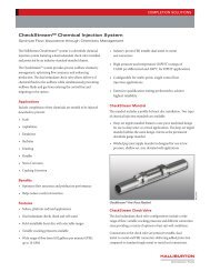
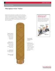
Special Report<br />
Multizone completion system swellable packer systems isolate various zones of a horizontal, openhole<br />
wellbore. All zones are stimulated in a single trip of the treating string. <strong>In</strong> this uncemented, openhole<br />
example, the ball-drop method was used to operate the completion system (Fig. 1).<br />
gies can address. For instance, high-performance,<br />
clay-free invert drilling fluids<br />
are available that can be formulated<br />
with a wide variety of base oils, including<br />
diesel, internal olefin, ester-olefin<br />
blends, and paraffin or mineral oil.<br />
The emulsion-based gel structure<br />
of the fluid helps eliminate barite sag,<br />
a serious issue often encountered with<br />
invert clay-based systems. Further, these<br />
fluids help reduce whole-mud losses<br />
by 41% on average, decreasing well<br />
costs and nonproductive time. The wide<br />
selection of base oils provides operators<br />
with options for minimizing environmental<br />
impact, conserving costs, and<br />
making use of readily available regionally<br />
acceptable base oils.<br />
The rheology of this system is managed<br />
through application of new emulsifiers<br />
and additives that replace conventional<br />
organophilic clays and lignite.<br />
The interaction of components in these<br />
clay-free systems is a key to providing a<br />
robust yet fragile gel structure. The gel<br />
strength develops rapidly to provide excellent<br />
suspension but is easily disrupted<br />
when circulation is initiated, even at<br />
very low pressures. This helps minimize<br />
or eliminate the pressure spikes that<br />
typically occur when breaking circulation<br />
with invert clay-based fluids.<br />
Other benefits of the clay-free fluid<br />
systems include:<br />
• Improved control over equivalent<br />
circulating density.<br />
• <strong>In</strong>creased tolerance to contaminants,<br />
including solids and water.<br />
• Smaller footprint on drillsite with<br />
fewer additives required for maintenance.<br />
• Real-time response to chemical<br />
treatments—no waiting for “yield.”<br />
• Thin filter cake and excellent return<br />
permeability values.<br />
Reserves<br />
optimization<br />
Optimizing development of tight gas<br />
sands can be difficult due to characteristically<br />
low permeability (
D r i l l i n g & Pr o d u c t i o n<br />
erties of the rock, but also its mechanical<br />
properties.<br />
These properties may be obtained<br />
from the following sources:<br />
• Well tests, logging, and core data.<br />
• Production analysis of offset well.<br />
• Stress-field measurements.<br />
• Understanding of reservoir fluid<br />
properties.<br />
• Study of the various completion<br />
strategies.<br />
3. Set optimization criterion or<br />
criteria (may include production and<br />
economic criteria).<br />
4. Define parameters that affect the<br />
optimum design, including reservoir<br />
properties, and fracture geometry, conductivity,<br />
and height.<br />
5. Achieve realistic modeling, a key<br />
to optimization of completion.<br />
Fig. 1 illustrates a multizone completion<br />
featuring swellable-elastomer<br />
packer systems isolating various zones<br />
of a horizontal wellbore.<br />
Hydraulic fracturing<br />
<strong>Unconventional</strong> (tight), continuoustype<br />
reservoirs, such as those in the<br />
Cretaceous of the northern Great Plains,<br />
are not well suited for conventional<br />
formation evaluation. Pay<br />
zones frequently consist only<br />
of thinly laminated intervals of<br />
sandstone, silt, shale stringers,<br />
and disseminated clay. Potential<br />
producing intervals are commonly<br />
unrecognizable on well<br />
logs and thus are overlooked.<br />
To aid in the identification<br />
and selection of potential<br />
producing intervals, Hester<br />
developed a calibration system<br />
that empirically links the gas effect to<br />
gas production. The calibration system<br />
combines the effects of porosity, water<br />
saturation, and clay content into a single<br />
gas-production index that suggests the<br />
production potential of different rock<br />
types. The fundamental method for<br />
isolating the gas effect for calibration is<br />
the interpretation of a crossplot of neutron<br />
porosity minus density porosity vs.<br />
gamma-ray intensity. 4<br />
The geomechanical effect on reservoir<br />
performance should always be<br />
considered, especially when producing<br />
from thick formations or creating multiple<br />
fractures in horizontal wells.<br />
Recovering fracturing fluids is often<br />
difficult in underpressured, tight, deep<br />
formations. CO 2<br />
, N 2<br />
, and binary highquality<br />
foams are widely used in this<br />
type of reservoir because of their capacity<br />
to energize the fluid and improve<br />
total flowback volume and rate. CO 2<br />
-<br />
and N 2<br />
-assisted (foam) fracs are also<br />
believed to allow less water to reach<br />
the formation matrix and, with their<br />
superior proppant-transport properties,<br />
allow use of far less gel.<br />
Reducing gel volume decreases the<br />
amount of gel likely to be left behind<br />
in the propped fracture; the result is believed<br />
to be greater conductive fracture<br />
half-length. The foam fracture fluid is<br />
full of energy and begins to flow back<br />
to the surface readily when fracture<br />
pumping has ceased. The energized<br />
fluid is especially helpful in promoting<br />
frac-fluid flowback where formations<br />
are depleted and have lost significant<br />
pore pressure due to production.<br />
Surfactants designed to reduce surface<br />
and interfacial tension are also key<br />
“To optimize returns on tight-gas assets,<br />
the primary objectives should be<br />
to strive for overall asset efficiency in<br />
drilling, stimulation, logistics, field surveillance,<br />
and operations, and to provide<br />
predictable delivery to maximize<br />
well rates and ultimate recovery.”<br />
elements in the design of fluid systems<br />
to enhance recovery and reduce entrapment<br />
of fluid barriers within the formation.<br />
Enhanced fluid recovery improves<br />
overall completion economics due to<br />
the lower total treatment cost and shorter<br />
time required for flowing back fluids.<br />
The most important benefit is achieving<br />
a less-damaged proppant pack, resulting<br />
in higher fracture conductivity.<br />
Fracturing horizontal wells<br />
Fracturing horizontal wells is the<br />
most promising production-enhancement<br />
technique in some formations.<br />
Fracturing in general is the more attractive<br />
completion option. It is even more<br />
attractive than multilateral completions,<br />
especially in tight, thick formations. <strong>In</strong><br />
general, horizontal lateral wells have to<br />
be fractured to improve the economical<br />
outlook of the well. The geomechanical<br />
effect on reservoir performance should<br />
always be considered, especially when<br />
producing from thick formations or<br />
creating multiple fractures in horizontal<br />
wells.<br />
Hydraulic-fracture stimulation can<br />
improve the productivity of a well in<br />
a tight-gas reservoir because a long<br />
conductive fracture transforms the flow<br />
path natural gas must take to enter the<br />
wellbore.<br />
After a successful fracture stimulation<br />
treatment, natural gas enters the<br />
fracture from all points along it in a<br />
linear fashion. The highly conductive<br />
fracture transports the gas rapidly to the<br />
wellbore. Later, the gas in the reservoir<br />
is flowing toward an elliptical pressure<br />
sink and most of the gas enters near the<br />
tip of the fracture.<br />
Conventional wisdom in<br />
designing hydraulic-fracture<br />
treatments for tight-gas<br />
sands suggests that successful<br />
stimulation requires creating<br />
long, conductive fractures<br />
filled with proppant opposite<br />
the pay zone interval. This is<br />
accomplished by pumping<br />
large volumes of proppant at<br />
high concentrations into the<br />
fractures, using fluids that<br />
can transport and uniformly<br />
distribute proppant deeply into the<br />
fracture. 5<br />
SurgiFrac<br />
Combined hydrajetting, fracturing,<br />
and jet-pump (CHF) technology<br />
is the first known successful method<br />
to resolve the problem of openhole<br />
fracture placement control by using<br />
dynamic diversion techniques. The technique<br />
(SurgiFrac) is a combination of<br />
three separate processes: hydrajetting,<br />
hydraulic fracturing (through tubing),
Special Report<br />
and coinjection down the annulus (using<br />
separate pumping equipment).<br />
One important aspect of this technique<br />
is the dynamic sealing capability.<br />
Unlike other techniques that require<br />
hardware-type packers or plugs, or even<br />
chemical plugs, this process essentially<br />
relies upon sealing by using fluid movement.<br />
Because packers are not used in<br />
most cases, the existence of passageways<br />
behind liner or through fractures rarely<br />
affects the performance of this process.<br />
The technique is based primarily on<br />
the Bernoulli principle, which states<br />
that the energy level of a fluid is generally<br />
maintained constant. To perform the<br />
SurgiFrac service, a jetting tool is placed<br />
near the toe of the well and used to jetperforate<br />
the casing and the formation<br />
rock, forming a 4-6-in. deep cavity.<br />
Based on the Bernoulli equation, as<br />
pressurized fluid exits the jetting tool<br />
the pressure energy is transformed into<br />
kinetic energy or velocity. Since the<br />
fluid velocity around the jet stream is at<br />
its greatest, pressure in this area is at its<br />
lowest, meaning the fluid does not tend<br />
to “leak” out somewhere. Conversely,<br />
fluid from the other areas of the well<br />
will flow into the jetted area.<br />
The fluid generally contains some<br />
abrasives to help the fluid penetrate the<br />
steel liner and the formation rock. As<br />
cavities are formed by each jet, highvelocity<br />
fluid impacts the bottom of<br />
the cavity (e.g., velocity becomes zero,<br />
an energy change from kinetic back to<br />
potential energy or pressure), causing<br />
pressure inside the rock to become high<br />
enough to create a fracture. Annulus<br />
pressure is then increased to help extend<br />
the fracture.<br />
After the fracturing process is completed,<br />
the tool is moved to the next<br />
fracturing position and another fracture<br />
is placed.<br />
The conversion of low-pressure,<br />
high-velocity kinetic energy to highpressure,<br />
low-velocity potential energy<br />
is extremely useful for fracture<br />
initiation and fracture placement. The<br />
breakdown pressure in a conventional<br />
treatment requires a tensile failure of<br />
the rock achieved by pressuring up the<br />
entire wellbore.<br />
Because, in most cases, fracture initiation<br />
pressure is much higher than fracture<br />
extension pressure, achieving multiple<br />
fracture initiation points along a horizontal<br />
wellbore requires achieving multiple<br />
fracture initiation pressures. This is very<br />
difficult in practice without some form of<br />
isolation along the wellbore.<br />
Since the energy of the jetting fluid<br />
is converted to pressure inside the<br />
eroded rock, the tensile failure of the<br />
rock occurs at the jetting point without<br />
exposing the wellbore to breakdown<br />
pressures. This enables precise control of<br />
the location of fracture initiation in the<br />
horizontal section. Multiple fractures<br />
can be created by simply moving the<br />
jetting tool to another location in the<br />
lateral and using hydrajet fracturing.<br />
Another attribute of the hydrajetting<br />
fracturing process is the creation of a<br />
dominant fracture through continued<br />
hydrajetting during fracture extension.<br />
As the fracture grows in width, the net<br />
pressure increase resulting from fracture<br />
extension induces stress normal to the<br />
direction of the fracture propagation; i.e.,<br />
reopening previous fractures becomes<br />
more difficult due to the increased stress<br />
induced by the dominant fracture.<br />
The SurgiFrac service has been applied<br />
successfully in a variety of fracturing<br />
conditions:<br />
• Multiple propped fractures in open<br />
hole.<br />
• Multiple acid fractures in open<br />
hole.<br />
• Deviated cased hole.<br />
• Horizontal slotted liner.<br />
• Coiled-tubing acid-frac to bypass<br />
damage.<br />
• Multiple fractures in a cased horizontal<br />
wellbore.<br />
A case history illustrates the utility<br />
of the multizone fracturing method.<br />
The first subsea CHF fracture stimulation<br />
was in 1,000 ft of water in Brazil’s<br />
Campos basin. Because the stimulated<br />
well had two branches (abandoned due<br />
to drilling problems), it behaved like a<br />
triple lateral for stimulation design. The<br />
treatment resulted in five acid fractures,<br />
completed in 2.5 days.<br />
Production rate for the first 15 production<br />
days following the treatment was<br />
almost double the maximum historical<br />
rate of this well and almost four times<br />
the monthly production rate during the<br />
months preceding the SurgiFrac. As a<br />
result of this treatment and two other<br />
treatments for proof-of-concept, a major<br />
international company has approved<br />
SurgiFrac service for all its scenarios—<br />
land, offshore, and subsea—worldwide.<br />
Microemulsion surfactants<br />
If the formation permits, often<br />
water-based hydraulic fracturing is carried<br />
out in tight gas formations. Traditionally,<br />
they have not been as optimally<br />
effective as they could be due to water<br />
blocking.<br />
A microemulsion surfactant (MS)<br />
has the potential vastly to increase the<br />
world’s recoverable reserves of natural<br />
gas from tight-gas reservoirs by helping<br />
control fracture-face damage and boosting<br />
production from these difficult<br />
formations.<br />
The special surfactant was designed<br />
to replace methanol or conventional<br />
surfactants. Based on new microemulsion<br />
technology (<strong>Gas</strong>Perm 1000), the<br />
surfactant helps remove water drawn<br />
into the formation during the fracturing<br />
process. Desaturating water and<br />
removing phase trapping can improve<br />
inflow of gas from the fracture face and<br />
help increase gas production.<br />
Tight-gas reservoirs (as well as<br />
coalbed methane and shale formations)<br />
typically have low production due to<br />
low permeability and-or low reservoir<br />
pressures. The low permeability<br />
of these formations creates a capillary<br />
effect, in which water can be drawn or<br />
“imbibed” into these tight formations<br />
during fracturing treatment.<br />
The low reservoir pressures do<br />
not create enough flow for the gas to<br />
displace the liquid from the formation.<br />
Phase trapping can occur, in which the<br />
liquid becomes trapped within the lowpermeability<br />
formation at the fracture<br />
face, and the gas cannot displace it. This<br />
trapped liquid can inhibit productiongas<br />
flows.<br />
Using a microemulsion surfactant<br />
can specifically mitigate fracture-face<br />
damage caused by capillary effects and
D r i l l i n g & Pr o d u c t i o n<br />
Special Report<br />
phase trapping.<br />
The surfactant<br />
can also enhance<br />
phase displacement<br />
and spatial flow<br />
behavior and help<br />
enhance mobility<br />
if liquid hydrocarbons<br />
are present.<br />
This can help increase recoverable<br />
gas and improve well economics by:<br />
1. <strong>In</strong>creasing actual production rates.<br />
2. <strong>In</strong>creasing recoverable reserves.<br />
3. Extending lifecycle of wells.<br />
4. Shifting projects above the economic<br />
threshold.<br />
The microemulsion additive is more<br />
effective at much lower concentrations<br />
than methanol, significantly reducing<br />
the volume required during fracturing<br />
treatment. It is a less flammable alternative<br />
to methanol-based fracturing fluids,<br />
thus improving safety and reducing<br />
environmental risk.<br />
The MS additive is compatible with<br />
both acidic and basic fluid systems and<br />
can be used as an acidizing additive or<br />
a fracturing fluid additive. The range of<br />
applications for this product continues<br />
to expand. MS service has been used in<br />
reservoirs with matrix gas permeability as<br />
low as the nanodarcy permeability range.<br />
Two case studies illustrate the effectiveness<br />
of this technology:<br />
• Ten horizontal shale wells in<br />
Oklahoma were recently completed<br />
with massive slickwater fracturing. Four<br />
of these wells were fractured with MS<br />
service and six wells did not have the<br />
MS treatment.<br />
Using MS, early load recovery improved<br />
by 43%. The surfactant reduced<br />
water saturation and capillary pressures<br />
along the fracture faces, which improved<br />
relative permeability to gas. The<br />
wells treated with MS had initial gas<br />
production rates comparable to the best<br />
wells in the field.<br />
• A Cotton Valley tight-gas sand in<br />
East Texas was fracture-stimulated with<br />
microemulsion surfactant. The well produced<br />
more than 14 times the wellhead<br />
pressure (100 psi vs. 1,400 psi) and almost<br />
doubled the initial production rate<br />
(862 Mcfd vs. 1,432 Mcfd) compared<br />
“Desaturating water and removing<br />
phase trapping can improve inflow of<br />
gas from the fracture face and help increase<br />
gas production.”<br />
to a conventionally treated offset well.<br />
Refracturing<br />
Hydraulic fracturing, especially in<br />
a horizontal well, is probably the best<br />
way to complete a well in a tight-gas<br />
formation. Fracture performance often<br />
declines with time, however.<br />
Reasons for performance degradation<br />
include:<br />
• Loss of fracture conductivity near<br />
the wellbore due to embedment.<br />
• Degradation of proppant with time<br />
and stress.<br />
• Loss of fracture height with time.<br />
• Loss of fracture length caused by<br />
degradation of proppant.<br />
• Loss of fracture conductivity from<br />
fines migration.<br />
• Loss of formation permeability<br />
near the fracture, forming a barrier.<br />
• Entrapment of liquid around the<br />
fracture face by capillary force. This<br />
effect may be aggravated by fluid loss<br />
during drilling and fracturing and by<br />
later movement of fines. This may be of<br />
special importance in tight-gas formations<br />
where a very high capillary pressure<br />
may be expected in cases having a<br />
water phase.<br />
Refracturing can expose more reservoir<br />
area to the high-conductivity fractures,<br />
thus improving well productivity<br />
and reservoir exploitation. ✦<br />
References<br />
1. Kuuskraa, Vello A., “A Decade<br />
of Progress in <strong>Unconventional</strong> <strong>Gas</strong>,”<br />
Advanced Resources <strong>In</strong>ternational, Arlington,<br />
Va., July 6, 2007.<br />
2. Tamayo, H.C., Lee, K.J., and Taylor,<br />
R.S., “Enhanced Aqueous Fracturing<br />
Fluid Recovery from Tight <strong>Gas</strong> Formations:<br />
Foamed CO 2<br />
Pre-Pad Fracturing<br />
Fluid and More Effective Surfactant<br />
Systems,” paper CIPC 2007-112, CIPC<br />
58th Annual Technical Meeting, Calgary,<br />
June 12-14, 2007.<br />
3. Evans, Scot, and Cullick, Stan,<br />
“Improving Returns on Tight <strong>Gas</strong>,” Oil<br />
and <strong>Gas</strong> Financial Journal, July 2007.<br />
4. Hester, Timothy C., “Prediction<br />
of <strong>Gas</strong> Production Using Well Logs,<br />
Cretaceous of North-Central Montana,”<br />
Mountain Geologist, Vol. 36, No. 2, pp.<br />
85-98, April 1999.<br />
5. Holditch, Stephen A., and Tschirhart,<br />
Nicholas R., “Optimal Stimulation<br />
Treatments in Tight <strong>Gas</strong> Sands,”<br />
paper SPE 96104, 2005 SPE Annual<br />
Technical Conf. and Exhibition, Dallas,<br />
Oct. 9-12, 2005.<br />
The author<br />
Glenda Wylie (Glenda.<br />
Wylie@<strong>Halliburton</strong>.com) is<br />
technical marketing director<br />
of unconventional resources at<br />
<strong>Halliburton</strong> Corp., Houston.<br />
She has also served as global<br />
technical marketing manager<br />
and in other positions in 13<br />
years at <strong>Halliburton</strong>. Prior to<br />
that, she worked with an operating company in<br />
exploration, engineering, and management. Wylie<br />
holds a BS (1975) in chemistry from Murray<br />
State Univ., a BS (1979) in chemical engineering<br />
from Texas A&M Univ., and an MS (1991)<br />
in engineering management from the Univ. of<br />
Alaska-Anchorage. She is also certified in corporate<br />
governance by Tulane Univ. Law School. Wylie is<br />
on the advisory board for the Drilling Engineering<br />
Association and is a member of AADE, API, SPE,<br />
Business Marketing Assoc., and National Assoc. of<br />
Female Executives.<br />
Mike Eberhard (Mike.Eberhard@<strong>Halliburton</strong>.<br />
com) is <strong>Halliburton</strong>’s technical manager for the<br />
Rockies, based in Denver. He has worked with <strong>Halliburton</strong><br />
nearly 27 years in pumping services, field<br />
engineering, sales, technical team, and management.<br />
Eberhard holds a BS in mechanical engineering<br />
from Montana State University. He is a member<br />
of SPE, AADE, DWLA, and is on the IAB for<br />
Montana Tech. Eberhard is a registered professional<br />
engineer in CO.<br />
Mike Mullen (Mike.Mullen@<strong>Halliburton</strong>.com) is<br />
a technical manager specializing in the integration<br />
of petrophysics, reservoir simulation, and economic<br />
stimulation design with <strong>Halliburton</strong> Energy<br />
Services in Denver. He began his career as a logging<br />
field engineer in Hobbs, NM in 1976 and has held<br />
positions in technical support, sales and formation<br />
evaluation over the past 31 years. Mullen<br />
holds a BS in electrical engineering (1976) from<br />
University of Missouri-Rolla and is a registered<br />
professional engineer in New Mexico and Colorado.<br />
He’s a member of SPE and SPWLA.
D r i l l i n g & Pr o d u c t i o n<br />
Low permeability<br />
shales are unconventional<br />
gas reservoirs that are<br />
being more efficiently<br />
exploited with newly<br />
developed production<br />
Production<br />
technologies.<br />
This series began<br />
last week, with an article discussing<br />
advances in fracture stimulation techniques<br />
and fluids used to improve tight<br />
gas production (OGJ, Dec. 17, 2007, p.<br />
39).<br />
The final article in this series, to be<br />
published next month, deals with coalbed<br />
methane (CBM) production.<br />
Shales<br />
There are technical difficulties in<br />
producing gas from shales, which have<br />
ultralow permeabilities and vary in<br />
brittleness. Multilayered shale reservoirs<br />
have widely varying reservoir characteristics<br />
and flow mechanism regimes.<br />
Formations typically have high capillary<br />
pressures in hydraulic fracturing scenarios.<br />
Treatment fluids can potentially<br />
damage shale formations.<br />
Multilayered shale reservoirs with a<br />
variety of reservoir characteristics require<br />
specialized evaluation and drilling<br />
techniques and “next-well” geological,<br />
seismic, and production comparisons to<br />
identify optimum fracturing targets.<br />
All of these data sources can be fed<br />
into custom models for a potential<br />
well’s production design. Combining<br />
logging systems with next-well and<br />
field-wide properties, geomechanics,<br />
and production performance data forms<br />
the basis of an advanced modeling system.<br />
The system is tailored for the specific<br />
shale-production mechanism and<br />
composition of the proposed new well’s<br />
drilling and completion design. Placing<br />
the well’s target location is critical and<br />
can be done with economical, simplified,<br />
rotary-steerable drilling assemblies<br />
in land-based shale wells.<br />
Determining proper fracture placement<br />
within shale formations is a key<br />
to creating large, highly productive<br />
fracture networks. Logging systems use<br />
an innovative approach, incorporating<br />
select mechanical rock properties,<br />
geomechanics, total organic content,<br />
and porosity to help locate the best<br />
fracture-initiation points within shale<br />
formations. Microseismic methods<br />
also provide invaluable information on<br />
the depth and width of the multiple<br />
fractures that are created during fracture<br />
stimulation.<br />
Due to shale’s<br />
ultralow permeability,<br />
successful economic<br />
productivity from a<br />
shale reservoir depends<br />
on the capability<br />
to maximize<br />
formation exposure through horizontal<br />
or vertical drilling and fracturing, or<br />
both.<br />
Economical rotary-steerable drilling<br />
assemblies, high-horsepower fracturing<br />
units, and multifunctional fractureplacement<br />
techniques provide maximum<br />
and optimized reservoir exposure.<br />
A complex reservoir’s brittleness<br />
must be leveraged through drilling and<br />
fracturing to create as much fracture<br />
face as possible to maximize gas migration<br />
from the producing shale. Brittleness<br />
can also be leveraged to create<br />
formation exposure through the use<br />
of high-horsepower fracture pumping<br />
units, which have been developed to<br />
provide maximum fracturing horsepower<br />
in a reduced environmental<br />
“footprint.”<br />
New designs include increased<br />
horsepower and high-rate pumps and<br />
offer improved safety, performance,<br />
reliability, space utilization, operational<br />
efficiency, real-time automation<br />
throughout the entire fracturing system,<br />
and ultimate improved gas recovery.<br />
Multilayer reservoir characteristics<br />
and ultralow formation permeability require<br />
precision fracturing of optimum<br />
locations along the wellbore, which has<br />
led to significantly improved production<br />
results.<br />
Pinpoint stimulation techniques have<br />
evolved, making shale more profitable<br />
as gas prices cycle. Multiple zones can<br />
UNCONVENTIONAL<br />
GAS TECHNOLOGY—2<br />
Custom technology makes<br />
shale resources profitable<br />
Glenda Wylie<br />
Ron Hyden<br />
<strong>Halliburton</strong> Corp.<br />
Houston<br />
Von Parkey<br />
Bill Grieser<br />
<strong>Halliburton</strong> Corp.<br />
Oklahoma City<br />
Rick Middaugh<br />
<strong>Halliburton</strong> Corp.<br />
Carrollton, Tex.<br />
Reprinted from the December 24, 2007 edition of OIL & GAS JOURNAL<br />
Copyright 2007 by PennWell Corporation
D r i l l i n g & Pr o d u c t i o n<br />
be efficiently fractured independently<br />
by:<br />
• Using coiled tubing or tubulars<br />
with hydrojetting techniques.<br />
• Using dynamic diversion techniques<br />
for either vertical or horizontal<br />
placement.<br />
• Or, incorporating completion mechanical<br />
downhole assemblies featuring<br />
stimulation sleeves and swellable<br />
elastomer packers to enable stimulation<br />
of multiple zones without use of bridge<br />
plugs to isolate intervals to be treated.<br />
These pinpoint stimulation<br />
techniques offer operators<br />
cost-effective methods to<br />
stimulate multiple zones in<br />
one rig-up.<br />
Fluid treatment<br />
Ultralow permeability<br />
is the primary challenge in<br />
shale formations. Fracturing<br />
fluids that are nondamaging<br />
and that enhance load<br />
recovery is essential in shale<br />
formations with very limited<br />
permeability. A combination<br />
of specialized chemistries<br />
delivers maximum effective<br />
fractures and preserves the<br />
formation’s existing permeability<br />
to gas, contributing<br />
significantly to the shaleproduction<br />
success. Components of the<br />
fracture fluids include:<br />
• Special friction reducers formulated<br />
to reduce potential fracture-face<br />
damage caused by long-chain polymers,<br />
without compromising their capability<br />
to reduce friction pressure.<br />
• Microemulsion surfactant that<br />
helps reduce capillary pressure, releasing<br />
imbibed treatment water and<br />
improving gas permeability. It also<br />
provides significant safety and environmental<br />
benefits by replacing methanol<br />
in water-block treatments.<br />
• Fracture-cleaning enhancer and<br />
conductivity enhancer for accelerating<br />
fracture cleanup and flowback of treatment<br />
fluids.<br />
Together, these components create a<br />
synergistic fluid treatment solution designed<br />
to help optimize gas production<br />
from formations with ultralow native<br />
permeability. The system provides workable,<br />
cost-efficient solutions for shale<br />
productivity programs from beginning<br />
to end—from analysis and planning to<br />
drilling, fracturing, early production,<br />
long-term production, and ultimate<br />
recovery/abandonment.<br />
The ability rapidly to fracture<br />
multiple independent zones yields a<br />
significant decrease in completion time.<br />
The components of the system work<br />
Makeup of productive shale formations<br />
<strong>In</strong> general, a productive shale formation includes<br />
these characteristics:<br />
• Zone thickness >100 ft.<br />
• Well bounded and containing energy.<br />
• Maturation in the gas window: R o<br />
= 1.1 to<br />
1.4.<br />
• Good gas content >100 scf/ton.<br />
• High total organic content (TOC) >3%.<br />
• Low hydrogen content.<br />
• Moderate clay content
improves environmental and safety performance<br />
by replacing methanol; and<br />
is effective in reservoirs with matrix<br />
permeability in the nano-Darcy range.<br />
Formation damage<br />
A new friction reducer helps reduce<br />
fracture-face damage from long-chain<br />
polymers. The maximum horsepower<br />
can be applied in a shale formation<br />
rather than being wasted just to get the<br />
fluid through the mechanical system.<br />
Because this reducer contains no phenols,<br />
it provides improved environmental<br />
performance and exhibits<br />
less flocculation than conventional<br />
friction reducers.<br />
A viscosity-reducing agent<br />
helps maximize the effectiveness<br />
of water-fracturing<br />
treatments by reducing fluid<br />
viscosity, improving load recovery,<br />
minimizing frictionreducer<br />
polymer damage,<br />
and preventing polymer adsorption<br />
to the fracture face,<br />
thereby enabling improved<br />
production.<br />
These purpose-focused<br />
technologies provide a<br />
holistic and economical<br />
approach to bringing forth<br />
energy from unconventional<br />
shale resources. Two cases demonstrate<br />
the use of the shale production system<br />
(SPS):<br />
• Case 1. A horizontal shale well was<br />
stimulated at four intervals with stimulation<br />
sleeves sequentially to isolate<br />
each interval of interest during treatment.<br />
The four intervals were fractured<br />
in 15 hr, placing 1.2 million lb of proppant<br />
with 2.3 million gal of fluid in a<br />
continuous operation.<br />
Normal stimulation practices would<br />
have required 2 days to run four traditional<br />
fracturing stages. The operational<br />
efficiency gained through the use of<br />
the stimulation-sleeve process reduced<br />
completion costs by 15-20%.<br />
• Case 2. <strong>Gas</strong> sales from six Barnett<br />
shale wells were compared after three<br />
of the wells had been treated with SPS<br />
additives and three were treated without<br />
additives. First gas production was<br />
quicker in the three wells treated with<br />
SPS additives and these wells produced<br />
100% more gas sales/day.<br />
The Mississippian Barnett shale<br />
serves as source, seal, and reservoir in a<br />
world-class unconventional natural gas<br />
accumulation in the Fort Worth basin of<br />
northcentral Texas. The Barnett is lithologically<br />
complex, with low permeability,<br />
and requires artificial stimulation to<br />
produce. 1<br />
• Case 3. Ten horizontal shale wells<br />
Shale technologies<br />
Several production-enhancement processes<br />
are useful in shale-gas reservoirs:<br />
• Prospect evaluation and core testing.<br />
• Shale lithotyping to determine key characteristics<br />
of productive shale.<br />
• Log data integration and analysis specific to<br />
shale.<br />
• Designing and drilling the vertical and horizontal<br />
well for stimulation.<br />
• Proppant size and loading considerations.<br />
• Optimization and tailoring water-frac fluid<br />
chemistry to the shale.<br />
• Remedial treatment processes for obtaining<br />
long-term sustained production.<br />
in Oklahoma were recently completed<br />
with massive slick-water fracturing.<br />
Four of these wells were fractured with<br />
microemulsion surfactant (MS) and six<br />
wells did not have the MS treatment.<br />
The MS treatment reduced water<br />
saturation and capillary pressures along<br />
the fracture faces, which improved relative<br />
permeability to gas. Wells using the<br />
MS service had initial gas production<br />
among the best wells in the field.<br />
Life-cycle phases<br />
Operators producing gas from shale<br />
reservoirs can be more successful by<br />
following the five life-cycle phases<br />
of project development and carefully<br />
choosing technologies appropriate for<br />
each project phase:<br />
1. Reservoir assessment. Evaluate shale<br />
and reservoir potential.<br />
2. Start-up exploration. Drill experimental<br />
wells and investigate fracture design<br />
and production prediction.<br />
3. Early development (mass production).<br />
Rapidly develop using an optimized design.<br />
Develop database and benchmarks.<br />
4. Mature development (reserve harvesting).<br />
During this cash-flow cycle, match<br />
production histories; adjust reservoir<br />
model; image database.<br />
5. Declining phase (maintenance and remediation).<br />
Identify remedial candidates,<br />
restimulate, initialize lift mechanisms<br />
and conformance methods.<br />
(Similar coalbed methane<br />
life-cycle phases are discussed<br />
in the final article in this<br />
series. 2 )<br />
Prospect evaluation<br />
Usually, the first step in<br />
the design and application<br />
process is to evaluate the<br />
shale prospect. <strong>In</strong>itially, both<br />
2D and 3D seismic data are<br />
processed to determine the<br />
extent of the shale play. The<br />
volume of shale is estimated<br />
in tons/acre (ton/acre-ft).<br />
<strong>Gas</strong> in place (GIP) is calculated<br />
from the geochemical<br />
determination of standard<br />
cubic feet/ton (scf/ton), as<br />
follows: GIP = (ρ)(1,359)(scf/ton) =<br />
scf/acre-ft.<br />
Shale samples collected from various<br />
sources help in determination of the<br />
commercial viability of the project. Factors<br />
include:<br />
• Shale hydrocarbon content (scf/<br />
ton, bbl/ton, GIP).<br />
• Shale maturity.<br />
• Kerogen type (Types I and II, oil;<br />
Type III, gas).<br />
• Shale porosity, permeability, oil,<br />
water, and gas saturations.<br />
• Shale desorption constant, or gas<br />
isotherm.<br />
• Shale bulk density, ρ (g/cu cm).<br />
Log data requirement<br />
A triple-combo log can be used to<br />
obtain density, gamma ray, resistivity,<br />
neutron, and density porosity.
D r i l l i n g & Pr o d u c t i o n<br />
A wave-sonic log should be run to<br />
obtain mechanical rock properties.<br />
An EMI (electromagnetic imaging)<br />
tool should be run to obtain natural and<br />
induced fracture direction, followed by<br />
analysis to identify sweet spots and a<br />
fracture-initiation site.<br />
A pulsed spectral gamma (PSG) log<br />
enhances hydrocarbon recovery by accurately<br />
measuring hydrocarbon saturations<br />
over a wide range of properties<br />
and borehole conditions. The PSG log<br />
also aids in clay typing, which adds to<br />
knowledge of the reservoir and is helpful<br />
information for planning future wells.<br />
Enhancing production<br />
Commercial production from shale<br />
depends largely on the gas content and<br />
natural storage and deliverability of the<br />
rock. The prime goal of stimulation is to<br />
contact and expose the greatest amount<br />
of rock volume and surface area with<br />
the least expensive material; in effect,<br />
“mining” the shale using hydraulic<br />
horsepower and injected water. This<br />
hydraulic mining can turn a well in<br />
nano-Darcy shale into a commercial gas<br />
producer.<br />
Restimulation has proven to increase<br />
recoverable reserves by 50-100%.<br />
Future vertical and horizontal wells<br />
are likely to be completed by selectively<br />
treating, isolating, and retreating<br />
unstimulated areas along the vertical or<br />
horizontal wellbore.<br />
Fracturing fluids and reactive fluids<br />
should be designed with knowledge of<br />
the specific shale mineralogy. The overall<br />
success of any shale play will include<br />
observation of the resource through its<br />
life cycle.<br />
Vertical well stimulation<br />
Current vertical stimulation designs<br />
feature:<br />
• Four or five perforation sites, 2-4<br />
ft long.<br />
• 5 shots/ft (spf) and 60° phasing.<br />
• Pump rates of 1-2 bbl/min per<br />
perf or 20 bbl/min per initiation site.<br />
Volumes pumped are about 2,500<br />
gal/ft, delivering 400 lb/ft of proppant.<br />
<strong>In</strong> early phases of the life cycle,<br />
vertical wells are usually drilled and<br />
completed to help the operator characterize<br />
the reservoir. With the experience<br />
gained from drilling, fracturing, and<br />
producing the vertical well, more comprehensive<br />
life cycle phases 3 and 4 can<br />
be planned and performed profitably.<br />
Horizontal well stimulation<br />
Current horizontal stimulation designs<br />
typically include:<br />
• Two to eight stages/horizontal<br />
wellbore.<br />
• Two to four frac initiation sites/<br />
stage.<br />
• 2-4 ft of perforations/site, with 6<br />
spf, at 60° phasing.<br />
• 20-30 bbl/min per frac site or 2-4<br />
bbl/min per perforation.<br />
• Volume average 1,800 gal/ft.<br />
Horizontal completions<br />
Horizontal well completions can be<br />
one of three types:<br />
1. Cased, cemented, multistage with<br />
composite plugs to separate frac stages.<br />
2. Multistage, with jetted sand and<br />
water delivered by coiled or jointed<br />
tubing to perforate zones.<br />
3. Mechanical bottomhole assembly.<br />
The cased, cemented, multistage<br />
completion with composite plugs is the<br />
most commonly used type of horizontal<br />
completion in shale wells. Each<br />
stage is perforated, fracture-stimulated,<br />
and isolated with a packer or bridge<br />
plug, allowing the next stage to be<br />
treated. The plugs and packers act as a<br />
well “bottom” for fracturing pressure<br />
to build up against. This process is the<br />
most time-consuming, due to the cycle<br />
time for perforating, plug-setting, and<br />
drilling out plugs or packers. Use of<br />
composite plugs reduces drillout times<br />
drastically.<br />
Jet-perforated, multistage completions<br />
eliminate the need to perforate or<br />
set plugs. This service is run on coiled<br />
or jointed tubing to the first-stage frac<br />
site; perforations and a tunnel are eroded<br />
by pumping through the tubing at<br />
a high differential pressure, using sand<br />
and water as the cutting stream. The<br />
fracture initiates and extends at the jet<br />
site; packers are not required because<br />
the jet velocity causes a pressure drop<br />
at the jet exit. The pressure drop pulls<br />
fluid from the annulus into the fracture.<br />
A more detailed discussion is provided<br />
in Part 1 (OGJ, Dec. 17, 2007, p. 39)<br />
Mechanical bottomhole assembly<br />
(BHA)-type completions isolation packers<br />
have been run in horizontal shale<br />
wellbores as a new alternative to cementing<br />
and perforating. These systems<br />
are deployed as part of the production<br />
casing and provide mechanical isolation<br />
and selective injection sites that can<br />
be opened and, in some cases, closed<br />
manually.<br />
Advancements have been made in<br />
the development of multistage frac-acid<br />
tools being applied in both openhole<br />
and cased-hole completions with<br />
hydraulic-set packers and sliding valves<br />
opened by pumping balls or shifting<br />
mechanical devices on jointed or coiled<br />
tubing.<br />
Water fracs produce a complex network<br />
of narrow-aperture fractures that<br />
can be either induced from extensive<br />
shear-failures (like shattered safety<br />
glass) or created from dilation of preexisting,<br />
incipient fractures or planes<br />
of weakness in the shale. The frac width<br />
must be 1.5± times the maximum<br />
grain diameter of the proppant to provide<br />
additional propping of the induced<br />
fractures.<br />
Because the permeability of the<br />
matrix rock is usually ultralow<br />
(0.0001-0.001 md), except possibly<br />
near the wellbore, the fracture conductivity<br />
typically does not need to be<br />
high; 20-50 md-ft is sufficient conductivity<br />
through the fracture network. The<br />
exception would be with deeper wells<br />
with higher closure pressure and rock<br />
properties that would allow proppant<br />
embedment. <strong>In</strong> a few cases, we have not<br />
seen much correlation between production<br />
and proppant size. Many created<br />
fractures remain open and conductive<br />
even without proppant.<br />
Many wells have been fractured<br />
proppant-free or with as little as 5,000<br />
to 10,000 lb yet achieved commercial
ates. Most Barnett shale well stimulations,<br />
however, are using proppant<br />
volumes in the range of hundreds of<br />
thousands of pounds. Although some<br />
operators question the value of proppants,<br />
with advancements<br />
in proppant<br />
design, correlating<br />
volume and type of<br />
proppant with actual<br />
production increases<br />
may be proved.<br />
Adaptation and<br />
modification of current<br />
fracture models<br />
calibrated to real-time<br />
microsiesmic mapping<br />
are being used to help<br />
in the design of stimulation<br />
treatments.<br />
Shale water-frac<br />
chemistry features<br />
application of friction<br />
reducers, surface-modification<br />
agents (SMA),<br />
microemulsions, deflocculants,<br />
and reactive fluids. The SMA<br />
helps minimize proppant settling, control<br />
production of fines, and enhance<br />
propped fracture conductivity. Microemulsion<br />
additives help remove water<br />
load and enhance recovery of fracturing<br />
liquids, resulting in significant uplift in<br />
recovery factors and estimated ultimate<br />
recovery (EUR).<br />
Friction-reducer deflocculants are<br />
added to prevent the potential negative<br />
impact friction-reducer polymers can<br />
have when interacting with formation<br />
fines and liquid hydrocarbon. Conventional<br />
friction reducers can essentially<br />
form damaging, gunk-like material<br />
within the created fracture system that<br />
can seal off frac conductivity in the<br />
narrow-aperture fractures.<br />
Refracturing<br />
Vertical shale wells can see production<br />
increases of 30-80% from reperforating<br />
the original producing interval<br />
and pumping a job volume that is at<br />
least 25% larger than the previous frac.<br />
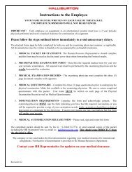
There are two obstacles in refracturing<br />
horizontal: The initial frac sites<br />
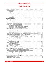
Hydraulic fracturing is a common completion technique in the Barnett shale. Photo from<br />
<strong>Halliburton</strong>.<br />
must be somehow isolated, and new<br />
frac sites must be created in areas of unstimulated,<br />
horizontal wellbore. Various<br />
completion methods such as <strong>Halliburton</strong>’s<br />
SurgiFrac and mechanical completions<br />
with swellable packers eliminate<br />
the obstacles.<br />
Shale-reactive fluids<br />
<strong>In</strong> general, shale is thought to be<br />
relatively nonreactive to low pH or<br />
acidic fluids because the clay, silt, and<br />
organic materials comprising the major<br />
components of shale formations exhibit<br />
insignificant bulk solubility in acid.<br />
Shale units are highly laminated, however,<br />
and contain acid-soluble minerals<br />
homogenized in the shale bulk matrix<br />
and natural fractures. X-ray diffraction<br />
analysis and scanning electron microscope<br />
images of shale samples show<br />
a great diversity and distribution of<br />
soluble material in the shale-producing<br />
unit.<br />
The amount of gas produced by desorption<br />
is directly related to the amount<br />
of surface area exposed, and a shalereactive<br />
fluid may increase the surface<br />
area of a newly created hydraulic<br />
fracture. <strong>Gas</strong> production from hydraulically<br />
fractured shale is believed to come<br />
from desorption and diffusivity from<br />
microporosity/fractures. Shale-reactive<br />
fluids may help remove acid-soluble<br />
minerals in the bulk shale as well as the<br />
mineral-filled fractures, thereby enhancing<br />
diffusivity of gas into the fracture<br />
network.<br />
The use of reactive<br />
fluids is a relatively<br />
new concept in shale<br />
stimulation, evolving<br />
from the observation<br />
that shale lithologies<br />
contain distributed low<br />
levels of acid-reactive<br />
minerals. <strong>In</strong> experimental<br />
trials of the use<br />
of weak-acid reactive<br />
systems, the unexpected<br />
pressure-drops that<br />
occur when the reactive<br />
fluids contact the shale<br />
formation inspired<br />
treatments of 20,000 to<br />
200,000 gal of reactive<br />
fluid through the frac<br />
water.<br />
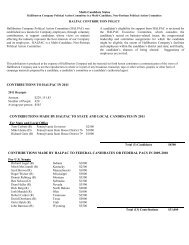
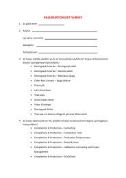
<strong>In</strong>itial production<br />
has been double that of treatments<br />
without reactive fluids included. Figs.<br />
1 and 2 show shales before and after<br />
being exposed to reactive systems. Early<br />
field trials are showing excellent production<br />
improvement results.<br />
Cementing shale wells<br />
Constructing a suitable cement<br />
sheath around the horizontal section of<br />
a shale well is a key element in the process<br />
of successful fracture-stimulation<br />
of shale-gas zones. <strong>In</strong> recent exploration<br />
and production activity in Oklahoma’s<br />
Woodford shale, wells cemented with<br />
foamed cement produced an average of<br />
23% more peak gas than wells cemented<br />
with conventional slurries.<br />
Conventionally cemented wells did<br />
not provide adequate zonal isolation<br />
and allowed fracturing fluid to communicate<br />
along the horizontal casing. This<br />
condition caused targeted intervals to<br />
receive less than the designed volume<br />
of stimulation fluid and proppant.<br />
Tensile strengths and mechanical<br />
properties of foamed cements make<br />
them ideal for zonal isolation in many
D r i l l i n g & Pr o d u c t i o n<br />
Shale fracture surface (left photo) shown before reactive fluid contact (1,000x magnification on ESEM microscope; Fig. 1). Here is the same shale fracture<br />
(right photo) surface as shown in Fig. 1 following contact with a reactive fluid. The result is an increase in effective surface area and enhanced flow channels for<br />
gas to diffuse from shale fracture surface into the created fracture void (Fig. 2).<br />
hydraulic-fracturing operations. The<br />
low compressive strengths of these cements,<br />
however, concern some operators<br />
that have long considered compressive<br />
strength to be the leading indicator<br />
of cement-sheath integrity in highpressure<br />
fracturing conditions.<br />
Foamed cement’s relatively low<br />
compressive strength does not increase<br />
the risk for fracture initiation<br />
and propagation in the cement sheath<br />
during hydraulic-fracturing treatments.<br />
Stresses induced in the cement sheath<br />
by increased wellbore pressures during<br />
casing-pressure tests or fracture<br />
stimulation treatments are tensile in<br />
nature. The sheath’s capacity to withstand<br />
these stresses is predominantly<br />
determined by the cement’s mechanical<br />
properties (Young’s modulus and<br />
Poisson’s ratio) and tensile strength.<br />
Cement compressive strength is of<br />
minimal importance. 3<br />
The durability of foamed cement<br />
has been demonstrated repeatedly in<br />
Woodford shale hydraulic-fracturing<br />
operations, where foamed cement<br />
outperformed conventional cement<br />
in withstanding high internal casing<br />
pressures and high fluid hydrostatic<br />
pressures.<br />
Two factors explain this performance:<br />
1. Mechanical properties of foamed<br />
cement allow it to withstand greater<br />
wellbore pressures than conventional<br />
cement.<br />
2. The ductile nature of foamed cement<br />
helps prevent the propagation of<br />
fractures in the cement sheath, helping<br />
ensure continued zonal isolation.<br />
Well-cementing professionals believe<br />
that the ductile properties of the cement<br />
allow it to yield to injection pressure<br />
rather than shattering as is usually<br />
the case in high-density, more brittle<br />
cement. Also, the cement-invasion distance<br />
may be less because of improved<br />
fluid loss provided by the nitrogen<br />
bubbles.<br />
Acid-soluble cement<br />
Zonal isolation for limited-entry<br />
stimulation can be provided by acidsoluble<br />
cements (ASC).<br />
Because conventional cements have<br />
a low solubility in acid, perforations<br />
can be difficult to break down and can<br />
inhibit fracture initiation and cause<br />
excess tortuosity during stimulation<br />
and production. Successful horizontal,<br />
limited-entry stimulation requires that<br />
all perforations are open and in communication<br />
with the formation and the<br />
designed perforation friction controls<br />
the fluid distribution along the wellbore.<br />
Unopened perforations and nearwellbore<br />
friction resulting from<br />
tortuosity caused by the conventional<br />
cement can significantly alter the fluid<br />
distribution and decrease stimulation<br />
effectiveness. Conventional high-compressive<br />
strength cements with a typical<br />
acid solubility of less than 5% cannot<br />
be reliably removed so that each perforation<br />
is openly communicating with<br />
the formation.<br />
<strong>In</strong>stead, acid-soluble cement can be<br />
used to provide zonal isolation without<br />
impeding stimulation and production.<br />
This type of cement has a fast solubility<br />
rate and is highly soluble (>90%) in<br />
acid-based stimulation fluids. ASC has<br />
physical properties much like conventional<br />
cement. It can be specifically formulated<br />
to provide the proper weight,<br />
fluid-loss, free water, compressive<br />
strengths, and pump times required for<br />
particular well conditions. Slurry densities<br />
and yield ratios can range from<br />
13.0 lb/gal to 15.8 lb/gal and 3.55 cu<br />
ft/sk to 2.00 cu ft/sk, respectively (sk =<br />
sack). ASC can also be foamed if lowerdensity<br />
slurries are needed.<br />
The easy removal of ASC material<br />
from the perforation cluster makes it<br />
especially suitable for limited-entry<br />
horizontal applications. The highsolubility<br />
allows the development of<br />
a larger communication area in the
annulus immediately adjacent to the<br />
perforations while still providing excellent<br />
zonal isolation along the wellbore.<br />
This pocket that is dissolved around the<br />
casing at the clustered perforation point<br />
eliminates the tortuosity and fractureentry<br />
pressure effects that could alter<br />
the planned limited-entry fluid distribution.<br />
Also, during production, the<br />
skin effects, reduced near-wellbore<br />
conductivity, and perforation-plugging<br />
problems associated with conventional<br />
cements are eliminated.<br />
Cement process<br />
The following well information is<br />
used to support an initial design for the<br />
foam-cementing process:<br />
• Operator well plan for casing<br />
strings, drillbit sizes, casing sizes,<br />
drilling mud systems, and if the well<br />
is horizontal, a proposed directional<br />
survey.<br />
• Depths and thickness of potential<br />
productive intervals and the fracture<br />
gradients and pore pressures of these<br />
intervals.<br />
• Depths, thicknesses, and fracture<br />
gradients of potential lost-circulation<br />
intervals.<br />
• Desired top of cement.<br />
Design software aids in developing a<br />
cementing process tailored for the well,<br />
and the recommended cement slurries<br />
are laboratory tested for performance.<br />
During drilling, the cementing program<br />
is updated to reflect the influence<br />
of events that were not expected, for<br />
example, encountering an unanticipated<br />
pressure zone.<br />
When well total depth is reached,<br />
initial well information is confirmed,<br />
drilling-mud reports are consulted, and<br />
drilling-mud and mixing-water samples<br />
are collected to be tested for compatibility<br />
with spacers.<br />
Updated wellbore information is<br />
entered into the planning program<br />
to develop a final cementing-process<br />
design. Several aspects of the design are<br />
updated in the software program:<br />
• Total depth.<br />
• Casing depths.<br />
• Size and grade of casing.<br />
• Bit size used for horizontal section.<br />
• Final directional survey.<br />
• Last 3 or 4 days’ drilling-mud<br />
reports.<br />
• Depths and fracture gradients of<br />
lost-circulation zones.<br />
The cementing operation is monitored<br />
and controlled by operating<br />
company and service company representatives<br />
to maximize opportunities to<br />
make real-time changes to the procedure.<br />
Other solutions<br />
<strong>In</strong> areas where alternatives to foam<br />
cement may be preferred, recent advances<br />
in well cementing technology<br />
have made it possible to provide the<br />
option of nonfoamed cements with<br />
the enhanced mechanical properties<br />
and ductility required to cement shale<br />
wells that will be fracture stimulated.<br />
These cements can also be designed to<br />
expand. The required mechanical modification<br />
additives can be dry-blended<br />
with cement and mixed and pumped in<br />
the field using conventional equipment.<br />
<strong>In</strong> practice, combinations of salts in<br />
cements and spacers and sodium silicates<br />
in preflushes in cementing fluids<br />
have provided a simple and proven<br />
means for managing shale instability<br />
during the cementing process when<br />
shale instability is considered to be an<br />
issue. ✦<br />
References<br />
1. Montgomery, Scott L., Jarvie, Daniel<br />
M., Bowker, Kent A., and Pollastro,<br />
Richard M., “Mississipian Barnett Shale,<br />
Fort Worth basin, north-central Texas:<br />
<strong>Gas</strong>-shale play with multi-trillion cubic<br />
foot potential,” AAPG Bull., Vol. 89, No.<br />
2 (February, 2005), pp. 155-175.<br />
2. Blauch, M.E., Weida, D., Mullen,<br />
M., and McDaniel, B.W., “Matching<br />
Technical Solutions to the Lifecycle<br />
Phase is the Key to Developing a CBM<br />
Project,” SPE 75684, SPE <strong>Gas</strong> Technology<br />
Symposium, Calgary, Apr. 30-May<br />
2, 2002.<br />
3. Deeg, W.F.J., “High Propagation<br />
Pressures in Transverse Hydraulic<br />
Fractures: Cause, Effect, and Remediation,”<br />
SPE 56598, SPE Annual Technical<br />
Conf. and Exhibition, Houston, Oct.<br />
3-6, 1999.<br />
The authors<br />
Ron Hyden (Ron.Hyden@<strong>Halliburton</strong>.com) has<br />
been group manager for stimulation at <strong>Halliburton</strong><br />
since 2005, based in Houston. He joined the company<br />
28 years ago, initially working in the East<br />
Texas and North Louisiana basins, and has since<br />
held positions in engineering, management, sales,<br />
and marketing. Hyden received a BS (1979) in<br />
chemical engineering from Texas A&M University<br />
and is a member of SPE.<br />
Von Parkey (Von.Parkey@<strong>Halliburton</strong>.com) is<br />
technical manager for the US Midcontinent at<br />
<strong>Halliburton</strong> and works in Oklahoma City. He<br />
has been with the company for 26 years and has<br />
worked in various pumping services positions; field<br />
engineering, sales, technical team, management and<br />
in training at the <strong>Halliburton</strong> Energy <strong>In</strong>stitute.<br />
Parkey holds a BS (1981) in agricultural<br />
engineering from Texas A&M University and is a<br />
member of SPE.<br />
Bill Grieser (Bill.Grieser@<strong>Halliburton</strong>.com) is<br />
an engineer and a member of the unconventional<br />
reservoir completions team at <strong>Halliburton</strong> Energy<br />
Services in Oklahoma City. He began his career<br />
with <strong>Halliburton</strong> in 1978 as a field engineer and<br />
has 29 years’ experience with fracture stimulation<br />
in Kansas, Colorado, Texas, and Oklahoma. Grieser<br />
is currently focused on completing horizontal<br />
wellbores and designing hydraulic fracture procedures<br />
in four Midcontinent shale plays (Barnett,<br />
Woodford, Caney, and Fayetteville). He earned a BS<br />
(1975) in nuclear engineering and BS (1978) in<br />
mechanical engineering from the Missouri School<br />
of Mines-Rolla. Grieser is a member of SPE, API,<br />
Texas Society of Professional Engineers, Oklahoma<br />
Society of Professional Engineers, and the National<br />
Society of Professional Engineers.<br />
Rick Middaugh (Rick.Middaugh@<strong>Halliburton</strong>.<br />
com) is the southeastern US technical manager for<br />
<strong>Halliburton</strong> Energy Services, based in Carrollton,<br />
Tex. Since joining <strong>Halliburton</strong> in 1977, Middaugh<br />
has worked in operations, technology, sales,<br />
and management positions in the Michigan basin,<br />
Appalachian basin, and Midcontinent. He has also<br />
worked throughout the US as the business development<br />
manager and asset manager of Wellnite, a<br />
<strong>Halliburton</strong> joint venture involving the use of nitrogen<br />
and CO 2<br />
in the oil field. Middaugh holds a<br />
BS (1977) in agricultural engineering from West<br />
Virginia University and is registered petroleum<br />
engineer in West Virginia and Texas.<br />
Glenda Wylie’s biography was published in Part 1,<br />
OGJ, Dec. 17, 2007, p. 39.
D r i l l i n g & Pr o d u c t i o n<br />
Life-cycle approach improves coalbed methane production<br />
Glenda Wylie<br />
<strong>Halliburton</strong> Corp.<br />
Houston<br />
Gary Rodvelt<br />
<strong>Halliburton</strong> Corp.<br />
Charleston, W.Va.<br />
Matt Blauch<br />
Richard D. Rickman<br />
<strong>Halliburton</strong> Corp.<br />
Duncan, Okla.<br />
John A. Ringhisen<br />
<strong>Halliburton</strong><br />
Oklahoma City<br />
Loyd E. East<br />
<strong>Halliburton</strong><br />
Houston<br />
Drilling<br />
This series on unconventional gas<br />
resources concludes with a discussion<br />
of technologies used in the recovery of<br />
coalbed methane and potential future<br />
research areas. The series has reviewed<br />
three main types of unconventional<br />
gas reservoirs:<br />
tight-gas, shale,<br />
and coalbed<br />
methane. The<br />
flow mechanisms<br />
of the different<br />
reservoirs increase<br />
in complexity<br />
from Darcy flow<br />
to Fick’s diffusion flow, and include<br />
combinations of other mechanisms.<br />
Many different technologies and<br />
methods have been effective in producing<br />
unconventional gas. Part 1<br />
(OGJ, Dec. 17, 2007, p. 39).discussed<br />
tight gas reservoirs and included such<br />
processes as hydrajet fracturing. 3 Part 2<br />
(OGJ, Dec. 24, 2007, p. 41) discussed<br />
shale gas and a variety of drilling, logging,<br />
and fluid treatment technologies.<br />
UNCONVENTIONAL<br />
GAS TECHNOLOGY—<br />
Conclusion<br />
Sorption<br />
Coal’s unique gas-storage mechanism<br />
is known as the “sorption” process,<br />
whereby gas molecules are packed<br />
tightly within the coal-matrix molecular<br />
pore system (Fig. 1). Concentration<br />
gradient causes gas to be released from<br />
the tens to hundreds of square meter<br />
surface area per gram of coal. Methane<br />
and other light gases diffuse (Fick’s<br />
Law) from the coal matrix toward a<br />
lower concentration.<br />
Coal can store many times its equivalent<br />
volume in gas because the gas<br />
molecules are packed tightly onto the<br />
surfaces of the coal. <strong>Gas</strong> adsorbed onto<br />
and within the coal macerals diffuses<br />
through a complex flow path of pores<br />
and cleats of varying sizes. The physics<br />
of migration is controlled by diffusion<br />
or diffusivity at various scales.<br />
Some coals are diffusion limited,<br />
while others are not. Water and<br />
sometimes gas exist at equilibrium<br />
gas saturation.<br />
Concentration<br />
gradients are most<br />
readily generated<br />
by removing this<br />
water or gas from<br />
the cleat system by<br />
reducing reservoir<br />
pressure. 1<br />
Methane sorption isotherms are used<br />
to help define a relationship between<br />
gas storage capacity and reservoir pressure;<br />
from this, a critical desorption<br />
pressure can be determined. Conventional<br />
porous-media fluid-flow concepts,<br />
such as Darcy’s law, relative permeability,<br />
and permeability anisotropy<br />
quantify reservoir mechanics after gas is<br />
released from the coal matrix. Methane<br />
extraction then occurs via a concentration<br />
gradient induced by removal of<br />
the free water or gas from the cleats as<br />
referenced above with effective stimulation<br />
or tailor-made well designs.<br />
Coalbed methane<br />
Conventional concepts can quantify<br />
reservoir mechanics after gas is released<br />
from the coal matrix, but coalbed<br />
methane (CBM) projects require earlier<br />
and more thorough evaluations than<br />
conventional projects. Therefore, CBM<br />
technologies, when viewed from a development<br />
life-cycle perspective, must<br />
depart from a conventional oil and gas<br />
approach in order to stack the odds for<br />
a commercial success.<br />
Historically, CBM projects include a<br />
few top-tier wells and many average-tomarginal<br />
wells. Because CBM prospectors<br />
rarely understand the up-front<br />
controlling factors that make a good or<br />
bad well, an investment in a regional<br />
view and multiwell approach early in<br />
the program is necessary so that the<br />
economically viable wells or acreage can<br />
be identified during start-up.<br />
<strong>In</strong> a technology-play CBM project,<br />
innovative applications of enabling<br />
technologies allow prospectors and<br />
operators to reduce cycle time before<br />
the first commercial gas sales. They can<br />
also screen and high-grade potential<br />
projects, add value to preproduction<br />
knowledge gathering, and validate economic<br />
forecasts that often must project<br />
much further into the future than those<br />
of conventional oil and gas reservoirs.<br />
Life-cycle concept<br />
CBM projects have five distinct lifecycle<br />
phases:<br />
1. Regional resource reconnaissance.<br />
2. Local asset evaluation.<br />
“Regulations and economics will require more efficiencies to be forthcoming.”<br />
—Glenda Wylie, technical marketing director of unconventional resources,<br />
<strong>Halliburton</strong> Corp.<br />
Reprinted with revisions to format, from the January 21, 2008 edition of OIL & GAS JOURNAL<br />
Copyright 2008 by PennWell Corporation
Free gas and sorbed gas exist in the coal matrix. The model image shows a depiction of a typical subbituminous<br />
coal at the molecular level (Fig. 1).<br />
3. Early development.<br />
4. Mature development.<br />
5. Declining production.<br />
A large-scale project may contain<br />
multiple localized projects, resulting in<br />
the simultaneous occurrence of all lifecycle<br />
phases.<br />
Fig. 2 presents a scenario in which<br />
an operator has leased several hundred<br />
thousand continuous acres of coal<br />
rights. The operator has been developing<br />
the asset for more than 15 years.<br />
Several areas in the lease are mature or<br />
experiencing declining production, but<br />
other areas have not yet been evaluated<br />
for production potential.<br />
<strong>In</strong> Phase 1, an operator determines<br />
whether a property has adequate production<br />
potential to justify an acquisition<br />
and exploration.<br />
<strong>In</strong> Phase 2, evaluations determine<br />
whether a specific area should be exploited<br />
and the most economic development<br />
methodology for exploiting it.<br />
<strong>In</strong> frontier exploration plays or<br />
basins, cycle time and costs must be<br />
optimized. The economic issues of<br />
remote operations further drive development<br />
of innovative strategies to<br />
help reduce evaluation time and allow<br />
go/no-go Phase 3 decisions. <strong>In</strong>herent<br />
highly variable coal-seam characteristics<br />
over short distances cause difficulties<br />
in extrapolating core hole and single<br />
test-well results. Consequently, basinwide<br />
evaluations or localized testing<br />
should be performed before a multiwell<br />
production pilot or development phase<br />
Enabling technologies matched to cbm life-cycle phases Table 1<br />
–––––––––––––– CBM life-cycle phase –––––––––––––<br />
Enabling technologies 1 2.1 2.2 2.3 3 4 5<br />
Geospatial well-pattern optimization X X<br />
Core and core analysis X X<br />
Well logging X X X X X<br />
Cleat permeability determination X X X X<br />
Reservoir engineering software tools X X X X X X X<br />
Prefracture diagnostics X X X<br />
Hydraulic fracture stimulation X X X X<br />
Multiseam coiled-tubing hydraulic fracturing X X X X<br />
Secondary production enhancement X X<br />
<strong>In</strong>fill drilling<br />
X<br />
activity.<br />
<strong>In</strong> Phase 3, initiation of development<br />
drilling in potential areas and attaining<br />
targeted project production is critical<br />
for capital investment.<br />
Phase 4 involves maintaining project<br />
production and economic targets<br />
through development of marginal areas,<br />
infill drilling, and remediation.<br />
Phase 5 can result in secondary<br />
recovery efforts as a means of extending<br />
economic viability. Declining production<br />
requires plugging of unproductive<br />
wells, removing equipment, and restoring<br />
the site while maintaining a positive<br />
cash flow.<br />
Fig. 3 illustrates a conceptual flow<br />
path for an example project. A phased<br />
approach may include separation of the<br />
single-cased well pilot holes as a Phase<br />
1 effort. This phased approach can be<br />
further evolved into a “minipilot.”<br />
Enabling technologies<br />
Over the years, many technologies<br />
and operating practices have evolved<br />
to help make CBM a viable energy<br />
resource. Ten specific enabling technologies<br />
may offer the best chance for<br />
projects to reach their life-cycle potential<br />
and span multiple life-cycle phases<br />
(Table 1):<br />
1. Geospatial well-pattern optimization.<br />
CBM geospatial well-pattern optimization<br />
requires an understanding of CBM<br />
production mechanics and reservoir<br />
simulation for production and economic<br />
forecasting. Although well spacing<br />
is usually a north-south and east-west<br />
grid, optimized well patterns are determined<br />
by reservoir characteristics, completion<br />
effectiveness, well-stimulation<br />
effects, drilling and completion costs,<br />
operating costs, and outside factors.<br />
For minimal cost, virtual simulation<br />
enables economic assessment, wellpattern<br />
comparisons, and completion<br />
options for hundreds of virtual wells.<br />
2. Core and core analysis. Scientific<br />
analysis of coal core can be critical to<br />
the success of Phases 1 and 2. Calculating<br />
gas in place from direct core<br />
measurements is a major first step in<br />
assessing methane gas reserves trapped
D r i l l i n g & Pr o d u c t i o n<br />
in the rock matrix. <strong>Gas</strong>-content determination<br />
is largely independent of the<br />
core porosity and permeability, but is a<br />
function of methane adsorption within<br />
the coal macerals.<br />
Prospectors may tend to rely on<br />
nonspecific seam lithotypes and assumed<br />
values for adsorption isotherms.<br />
<strong>Gas</strong> contents are calculated with assumed<br />
isotherms, reservoir pressures,<br />
and gross seam thickness. Although<br />
these estimates are appropriate during<br />
early prospect evaluation, they must be<br />
validated through direct-core measurement<br />
in Phase 2. A complete coal-seam<br />
anatomy can be obtained and applied to<br />
the macroscale reservoir.<br />
3. Well logging. Significant technical<br />
breakthroughs in well logging<br />
have been developed specific to CBM.<br />
Perhaps the greatest advances involve<br />
log-processing methods and core-log<br />
integration techniques. Table 2 provides<br />
recommended log suites for projects in<br />
Phases 2 through 5.<br />
Electric microimaging (EMI) logging<br />
may provide the closest thing to a continuous<br />
core as currently possible. It can<br />
be integrated with the whole core so<br />
that grayscale levels can be correlated to<br />
discrete core lithology. Such integration<br />
can be performed in one well and applied<br />
across the field or basin that lacks<br />
core information.<br />
4. Cleat permeability determination. Three<br />
technologies are potentially available<br />
for cleat permeability determination<br />
and are applied predominantly through<br />
Phases 2 and 3:<br />
• Openhole discrete-seam drillstem<br />
testing (DST).<br />
• <strong>In</strong>terference testing and injection<br />
fall-off.<br />
• G-function derivative analysis.<br />
DST technology can enable the highgrading<br />
of discrete seams for subsequent<br />
production during the corehole<br />
process. Multiwell interference testing<br />
can enable the acquisition of far-field<br />
regional cleat permeability and permeability<br />
anisotropy. G-function analysis,<br />
primarily used for comparing regional<br />
variations, can enable near-field qualitative<br />
cleat permeability information to<br />
PROJECT LIFE-CYCLE PHASES Fig. 2<br />
Phase 1—<br />
Core / single well<br />
Phase 4—<br />
60 wells mature<br />
Phase 1—<br />
5-spot<br />
Phase 1—5-spot<br />
Phase 1—Core / single well<br />
be obtained in conjunction with the<br />
hydraulic fracturing parameters.<br />
5. Primary hydraulic fracture stimulation.<br />
Very few coal-seam gas reservoirs can<br />
produce commercial rates of methane<br />
without some type of primary production<br />
enhancement. Three primary<br />
proven stimulation technologies have<br />
been developed for enhancing CBM<br />
production: cavitation, underreaming,<br />
and hydraulic fracture stimulation. Historically,<br />
the most effective technology<br />
Phase 1—Core / single well<br />
Phase 3—22 wells early<br />
Phase 5—180 wells mature / declining<br />
Phase 1—5-spot<br />
Phase 2— Phase 1—Core / single well<br />
12 wells early<br />
Phase 2—16 wells early<br />
Phase 3—40<br />
Phase 1—5-spot<br />
wells early<br />
2 x 2<br />
Phase 1— 5–spot<br />
Phase 1—<br />
Core / single well<br />
INTEGRATING RESOURCE-ASSESSMENT, SIMULATION DATA Fig. 3<br />
1<br />
Core desorption<br />
2<br />
Openhole log<br />
OH test information<br />
3<br />
Coal-seam diffusivity<br />
data<br />
8<br />
Multiseam<br />
production results<br />
10<br />
Reservoir<br />
production model<br />
and extractable<br />
reserves<br />
evaluation<br />
7<br />
Geologic and stratigraphic<br />
information<br />
2 x 2.5<br />
9<br />
Single-seam<br />
production results<br />
6<br />
Coal core study<br />
information<br />
4<br />
Regional permeability/<br />
interference test data<br />
5<br />
Regional and core-based<br />
fracture analysis<br />
appears to be hydraulic fracturing although<br />
novel stimulated horizontal and<br />
complex wells are rapidly becoming<br />
viable alternatives to traditional vertical<br />
hydraulically fractured wells.<br />
<strong>In</strong> the early phases, a technically,<br />
rather than economically, optimal<br />
fracturing system is critical to acquire<br />
valid gas and water producibility data<br />
for subsequent reservoir simulation<br />
and sensitivity analysis. Early development<br />
of fracture-design simulation<br />
No. z080121OGJdwy02.eps<br />
No. z080121OGJdwy03.eps
model(s) can match the outcome of the<br />
development-phase treatments and provide<br />
dependable predictions for future<br />
economic fracture treatments.<br />
Recent technological developments<br />
have enhanced hydraulic fracturing for<br />
CBM resource evaluation. Because the<br />
indiscriminate application of fracturing<br />
fluids to coal reservoirs<br />
contributes to production<br />
performance, identifying an<br />
optimal fracturing system<br />
during resource evaluation<br />
phase is critical.<br />
Economic constraints<br />
regarding mobilization and<br />
logistics, especially in frontier<br />
regions where little or no<br />
service infrastructure exists,<br />
largely drive fracture design<br />
decisions. If the goal of a<br />
single test well in a frontier<br />
region is to demonstrate that free gas<br />
can be produced to verify gas saturation,<br />
then a relatively small, low-cost<br />
hydraulic fracture design may be more<br />
appropriate than one designed for fullscale<br />
production.<br />
6. Secondary production enhancement.<br />
During the final two life-cycle phases,<br />
technologies focusing on secondary<br />
production enhancement are increasingly<br />
important for extending the life of<br />
the CBM field.<br />
Technologies enabling the extension<br />
of Phases 4 and 5 include the following:<br />
• Hydraulic refracturing of previously<br />
fractured wells.<br />
• Hydraulic fracturing of previously<br />
cavity-completed wells.<br />
• Chemical-enhancement additives<br />
designed to mitigate specific impairment<br />
mechanisms included as part of<br />
the hydraulic fracturing system. Such<br />
remedial “backflush” technologies can<br />
be economic, repeated on the same<br />
well, and extend Phase 4 for years.<br />
7. <strong>In</strong>fill drilling. Tapping into new<br />
reservoirs in a development field is<br />
an enabling technology because it has<br />
significantly helped extend Phases 4 and<br />
5 of a mature CBM prospect. Because<br />
infrastructure investments have been<br />
capitalized, combining this approach<br />
with secondary production-enhancement<br />
methods offers a solution to stopping<br />
or stabilizing field or basin-wide<br />
production declines.<br />
Reservoir modeling and historymatching<br />
the field’s cumulative production<br />
can help identify infill-drilling<br />
candidates. Combined with geospatial<br />
Recommended log suites for specific phases Table 2<br />
–––––––– Phase –––––––<br />
Log suite 2 3 4 5<br />
High-resolution spectral density log X X X<br />
High-resolution gamma ray X X X<br />
High-resolution dual-spaced neutron X X<br />
High-resolution induction X X<br />
Microlog X X X<br />
Magnetic resonance imaging log (if applicable) X X<br />
Electric microresistivity imaging log<br />
Wave sonic tool (dipole sonic)<br />
Thermal multigate decay pulsed neutron (if<br />
also evaluating sands) run through casing<br />
Dual-spaced neutron (if not evaluating<br />
sands) run through casing<br />
X<br />
X<br />
well-pattern optimization, infill drilling<br />
can be optimized for a given asset within<br />
a basin or field. Emerging technology<br />
involving multilateral and directional<br />
drilling may eventually replace verticalwell<br />
infill drilling for CBM. Currently,<br />
economics are looking more favorable<br />
for widespread application of innovative<br />
multilateral and directionally drilled<br />
well completions in coal.<br />
8. Treatment selection. Determining an<br />
optimum stimulation treatment involves<br />
experimentation, but the following<br />
guidelines can help operators avoid<br />
misapplications and decrease the learning<br />
curve. The following steps can be<br />
used for planning treatments in areas<br />
where few or no CBM completions have<br />
been performed.<br />
Typically, coalbeds are categorized<br />
by:<br />
• Type of coal, coal thickness, and<br />
stratigraphy.<br />
• Proppant needs and desired proppant<br />
concentrations.<br />
• Field economics, including service<br />
costs, accessibility and availability, and<br />
potential gas rates.<br />
• Cleanup concerns or needs for<br />
long-term dewatering of well.<br />
• Job design process, including<br />
frac-modeling simulation (pressuredependent<br />
leakoff (PDL) concerns, rate<br />
effects, etc.).<br />
When a well contains several coal<br />
seams that will act as producing zones,<br />
differences between zones may prevent<br />
the success of a single fracture design.<br />
Economics seldom allow operators to<br />
pump optimum jobs for each zone,<br />
even when the zones are<br />
X<br />
X<br />
fractured separately.<br />
9. Optimizing hydraulic<br />
technology. Helping to define<br />
hydraulic technology should<br />
be considered early and<br />
evolve throughout the entire<br />
lifecycle, particularly in the<br />
local asset evaluation, single<br />
test well, and five-spot subphases.<br />
Fracturing fluids selection<br />
and optimization for<br />
hydraulic-fracturing technology<br />
is key in the local asset<br />
evaluation, single test well, and fivespot<br />
subphases. <strong>In</strong> these early phases, a<br />
technically optimal fracturing system is<br />
critical in acquiring valid gas and water<br />
producibility data for subsequent reservoir<br />
simulation and sensitivity analysis.<br />
Later in the well’s life, emphasis can be<br />
shifted from technology to efficiency<br />
optimization.<br />
Realistically, the time in which an<br />
optimum fracturing design can be<br />
achieved depends on several factors,<br />
including the following:<br />
• The volume of available information<br />
about the seam(s) that will be<br />
fracture stimulated.<br />
• How this CBM reservoir responds<br />
to fracturing compared to existing CBM<br />
reservoirs. Fracturing treatments that<br />
incorporate the use of fines control and<br />
surface modification agent (SMA) provide<br />
both fines and proppant flowback<br />
control. This allows the operator to<br />
produce the wells with the pump at or<br />
below the lowest perforations for optimum<br />
efficiency. <strong>In</strong>creased run times<br />
with fewer workovers improve the dewatering<br />
efficiency, shortening the time<br />
to maximum gas desorption.<br />
• The technical background and<br />
CBM stimulation experience of the team<br />
member(s) responsible for developing
D r i l l i n g & Pr o d u c t i o n<br />
the fracturing program.<br />
10. Multiseam pinpoint hydraulic fracturing.<br />
One of the most significant enabling<br />
technologies for CBM in recent years<br />
involves technologies that enable the hydraulic<br />
fracturing of multiseam completions.<br />
Another fracture stimulation option<br />
for multiseam completions (not involving<br />
coiled tubing) is the conventional<br />
“Perf & Plug” method using conventional<br />
wireline perforating and composite<br />
bridge plugs that set quickly and<br />
are easily drilled out at the end of the<br />
completion.<br />
Using coiled tubing, there are<br />
several new methods for isolating and<br />
fracturing individual coal seams, some<br />
of which involve hydra-jet perforating<br />
(Fig. 4). These methods were<br />
developed to minimize or eliminate<br />
non-productive time by planning the<br />
entire completion to be performed in<br />
a single trip. Coiled tubing fracturing<br />
technology allows placement of 30,000<br />
to 100,000 lb/proppant per coal seam<br />
With pump time of about 1 hr/seam,<br />
three to seven stages have been successfully<br />
treated in a single day. For shallow<br />
CBM wells, as many as 24 intervals in<br />
two separate wells have been fracture<br />
stimulated in a single day with the same<br />
crew and equipment.<br />
CobraMax fracturing service uses hydra-jet perforating and proppant plug diversion to fracture multiple<br />
intervals, vertically and horizontally (Fig. 4).<br />
Defeating coal fines<br />
A patented fines locking backflush<br />
service (FLBS) incorporating aqueous<br />
tackifier technology provides a process<br />
to help remove wellbore damage while<br />
locking down formation fines to restrict<br />
their mobility (CoalStim). It can be<br />
used during the initial stimulation job<br />
or in remedial stimulation jobs. FLBS<br />
chemicals initially act as “clotbusters,”<br />
breaking apart the internal bridges and<br />
agglomerates, and then act as “clotformers,”<br />
imparting a “tacky” surface to<br />
the coal particle surfaces.<br />
FLBS has been used to return hundreds<br />
of CBM wells in the western US to<br />
their initial production rates and extend<br />
the life of these highly profitable fields.<br />
Other key functions of the FLBS<br />
chemistry are to degrade residual polymer<br />
remaining from previous gelledfracturing<br />
operations and dissolve in<br />
situ geochemical precipitates or carbonate<br />
scales that may be contributing to<br />
premature production declines.<br />
Coal fines tend to collect in both<br />
proppant and cleat porosity; eventually,<br />
such plugging may damage permeability<br />
and conductivity. FLBS causes fines<br />
to segregate and then adhesively bond<br />
together in larger groupings that bond<br />
onto proppant or cleat surfaces while<br />
keeping flow channels open to flow.<br />
Benefits of applying FLBS postfracture<br />
service in mature CBM fields<br />
include:<br />
• Extend well productive life.<br />
• Economically treat wells/field.<br />
• Accelerate well pay out.<br />
• <strong>In</strong>crease success rate.<br />
• Lower financial risk.<br />
• Add significant reserves to existing<br />
assets.<br />
The fines control technology can be<br />
applied in both primary stimulation and<br />
remedial treatment application modes.<br />
Field case history<br />
A look-back study was conducted<br />
from a mature Phase 4 CBM project in<br />
the western US in which a total of 495<br />
FLBS treatments were reviewed. The objective<br />
of the project was to extend the<br />
life of the field as it was approaching<br />
Phase 5. Results showed an average per<br />
well gas increase of 15,696 Mscf/well<br />
and 312 bbl/well increase in water over<br />
a 6 month period. This translated to an<br />
overall 4,500 % increase in gas volume<br />
and a project ROI of over 2000%.<br />
Future technologies<br />
No one individual technology can<br />
make unconventional assets profitable. A<br />
comprehensive holistic approach must<br />
be taken into account beginning with<br />
seismic and continuing through to last<br />
stage of production including plug/<br />
abandonment. Future exploitation of<br />
unconventional gas sources will require<br />
development and-or refinement of several<br />
technologies:<br />
• Deformable proppants<br />
• Partial monolayer proppant designs<br />
• Proppant transport<br />
• Improving proppants and fluids<br />
that are better tailored to formations.<br />
• Create a better understanding of<br />
reservoirs by improving reservoir modeling<br />
and description<br />
• Better prevention of circulation<br />
losses while drilling.<br />
• Recycling and purification of water<br />
used in well-service functions.<br />
• Reducing emission to the atmosphere<br />
• Minimize land use through centrally
located rigs and fixed-plant hydraulic<br />
fracturing operations serving many wells.<br />
• Improved efficiency.<br />
• <strong>In</strong>creasing simultaneous operations,<br />
e.g., drilling, stimulation, and<br />
production at the same time.<br />
• Improving automation and realtime<br />
operations for improving learning<br />
and reducing manpower requirements.<br />
• Improving recovery processes for<br />
ultra low pressure reservoirs, including<br />
improving artificial lift and improved<br />
recovery processes<br />
Acknowledgments<br />
The authors thank <strong>Halliburton</strong> management<br />
for their support and permission<br />
to publish the unconventional<br />
article series. ✦<br />
References<br />
1. Blauch, M.E., Weida, D., Mullen, M.,<br />
and McDaniel, B.W., “Matching Technical<br />
Solutions to the Lifecycle Phase is the Key<br />
to Developing a CBM Project,” SPE 75684,<br />
SPE <strong>Gas</strong> Technology Symposium, Calgary,<br />
Apr. 30-May 2, 2002.<br />
2. Smith, Michael, Blauch, Matt,<br />
and Welton, Thomas, “Process increases<br />
CBM production,” Hart’s E&P, November<br />
2004.<br />
3. Surjaatmadja, J.B., Grundmaan,<br />
S.R., McDaniel, B., Deeg, W.F.J., Brumley,<br />
J.L., and Swor, L.C., “Hydrajet fracturing:<br />
An Effective Method for Placing Many<br />
Fractures in Openhole Horizontal Wells,”<br />
paper SPE 48856, SPE <strong>In</strong>ternational Conf.<br />
& Exhibition, Beijing, Nov. 2-6, 1998.<br />
4. East Jr., Loyd, Grieser, William,<br />
McDaniel., B.W., Johnson, Bill, and<br />
Fisher, Kevin, “Successful Application of<br />
Hydrajet Fracturing on Horizontal Wells<br />
Completed in A thick Shale Reservoir,”<br />
paper SPE 91435, 2004 SPE Eastern<br />
The authors<br />
Gary Rodvelt (Gary.Rodvelt@Hallibuton.com)<br />
began work in the Midcontinent (Illinois) division<br />
and now works on Applalachian basins –unconventional<br />
reservoirs. <strong>In</strong> 28 years, he has worked in<br />
management, sales/marketing and engineering.<br />
Rodvelt graduated from Kansas State University<br />
with nuclear engineering (BS). He is a member of<br />
Society of Petroleum Engineers and the Appalachian<br />
Geologic Society and has published numerous<br />
coalbed methane papers and other unconventional<br />
reservoir focused papers.<br />
Matt Blauch (Matt.Blauch@<strong>Halliburton</strong>.com) is<br />
a principal technical professional in <strong>Halliburton</strong>’s<br />
production enhancement group. He has more than 20<br />
years’ experience in the industry, including 15 years<br />
working with unconventional gas, focused on CBM<br />
and shale gas. He graduated from Juniata College,<br />
Huntingdon, Penn., with a BS (1982) in geology<br />
and then earned an MS (1988) in geology from the<br />
University of Akron. He is a member of the American<br />
Association of Petroleum Geologists and SPE.<br />
Richard D. Rickman (Richard.Rickman@<strong>Halliburton</strong>.com)<br />
is a senior scientist (chemist) at <strong>Halliburton</strong>’s<br />
Duncan Technology Center in Duncan,<br />
Okla., where he works in both the fracturing and<br />
sand control groups. Rickman graduated from Texas<br />
Regional Meeting, Charleston, West<br />
Virginia, 15-17 September 2004.<br />
5. Romer, W. C., Phi, M. V., Barber, R.<br />
C., and Huynh, D. V., “Well Stimulation<br />
Technology Progression in Horizontal<br />
Frontier Wells, Tip Top/Hogsback Field,<br />
Wyoming,” paper SPE 110037, 2007<br />
SPE Annual Meeting, Anaheim, Nov.<br />
11-14, 2007.<br />
A&M University with a PhD (2004) in chemistry.<br />
He is a member of SPE and the American<br />
Chemical Society.<br />
John Ringhisen (John.Ringhisen@<strong>Halliburton</strong>.<br />
com) has been with <strong>Halliburton</strong> for 36 years in<br />
various field pumping services assignments, sales<br />
and service line management positions. Based<br />
in Oklahoma City, he concentrates on cementing<br />
issues for the midcontinent area. Ringhisen<br />
received a BS (1969) in petroleum engineering<br />
from Marietta College, Ohio, and he is a<br />
member of SPE.<br />
Loyd East (Loyd.East@halliburton.com) is currently<br />
global pinpoint stimulation manager at <strong>Halliburton</strong>.<br />
He has been working in the oil and gas<br />
industry for more than 26 years. East’s most recent<br />
work is in multiple-interval well completions and<br />
horizontal well stimulation. His previous assignments<br />
include engineering positions in technology<br />
and instructor at the <strong>Halliburton</strong> Energy <strong>In</strong>stitute.<br />
East earned his BS (1980) in agricultural<br />
engineering from Texas A&M University; he is a<br />
member of SPE.<br />
Glenda Wylie’s biography was published in Part 1,<br />
OGJ, Dec. 17, 2007, p. 45.
H06060<br />
www.HALLIBURTON.com