Operators Manual - Halton Company
Operators Manual - Halton Company
Operators Manual - Halton Company

Create successful ePaper yourself
Turn your PDF publications into a flip-book with our unique Google optimized e-Paper software.
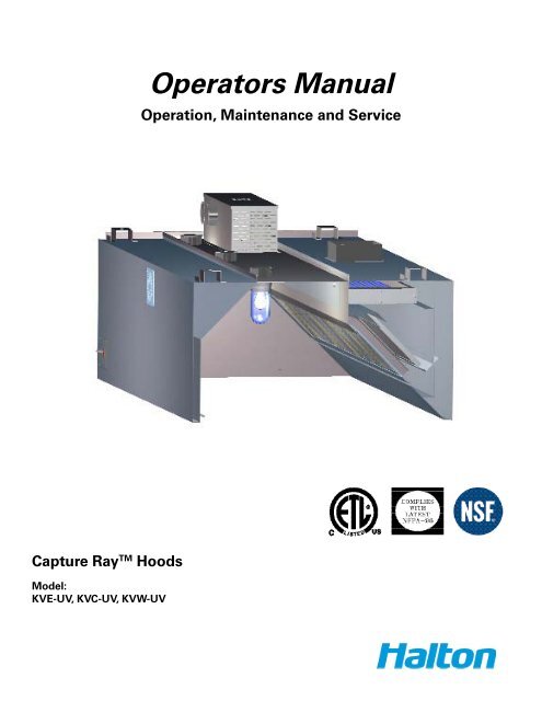
<strong>Operators</strong> <strong>Manual</strong><br />
Operation, Maintenance and Service<br />
Capture Ray TM Hoods<br />
Model:<br />
KVE-UV, KVC-UV, KVW-UV
INSTALLATION INSTRUCTIONS<br />
Suspending and Mounting<br />
Determine location of 1/2” (13mm) diameter handing rods. All thread rods are recommended for<br />
use with front support brackets provided. All hanging rods should have double nuts. Rods should be<br />
threaded 4” (102mm) minimum for verticle adjustment. See figure 1. Handing rods by installer.<br />
Exhaust hoods are shipped in maximum lengths of 14’-0”. When installing multiple sections, we<br />
recommend hanging the section individually then fasten together as per the installation drawing. See<br />
figure 2.<br />
Install U-channel strips provided on multiple bank sections between interior section ends at bottom. All<br />
exhaust hoods must be hung level and plumb.<br />
Note:<br />
Allow 100lbs (45kg) per linear foot hanging weight.<br />
Do not lift exhaust hoods from their end panels. Lift from four corners<br />
All exhaust hoods and control panels are fitted together and factory tested prior to shipping<br />
for alignment and operation.<br />
Duct Connections<br />
Duct connections meet NFPA 96 of applicable local codes. Size of connection is indicated on exhaust<br />
hood drawing. Connection to be made after exhaust hood is hung.<br />
PROPER LOCATION IS ESSENTIAL<br />
Locating the exhaust ventilator with sufficient overhang over the cooking equipment is manditory for<br />
proper capture and extraction of grease and smoke.<br />
It is important that the installer check with Kitchen Equipment Contractor for accurate location of the<br />
cooking bank, exhaust hood and control panel.<br />
Exhaust hood shop drawings show recommended mounting height from finsihed floor to underside of<br />
exhaust hood at front edge. All hanging bracket locations are also indicated. Electrical, ductwork and air<br />
requirements are also indicated on the exhaust hood show drawings.<br />
Capture Ray TM Operation & Maintenance & Service <strong>Manual</strong><br />
2<br />
CJUV/012009/rev1/EN
FIGURE 1<br />
HOOD INSTALLATION DETAILS<br />
40" MIN.<br />
HANGER BRACKET<br />
DETAIL<br />
1/2" ALL THREAD<br />
(BY OTHERS)<br />
16 GA. DUCT WORK<br />
ALL WELDED PER CODE<br />
WELDED TO<br />
TOP OF HOOD<br />
1/2" ALL THREAD<br />
(BY OTHERS)<br />
HANGER BRACKETS<br />
OPTIONAL TURNBUCKLES<br />
(BY OTHERS)<br />
18 GA.<br />
MAT'L<br />
1/2" THREADED NUT<br />
(BY OTHERS)<br />
2 "<br />
1/2" NUTS<br />
(BY OTHERS)<br />
DROP<br />
CEILING<br />
1.25"<br />
4"<br />
1.25"<br />
3 "<br />
CANOPY<br />
HOOD<br />
EXHAUST<br />
DUCT<br />
CONTINUOUS<br />
LIQUID TIGHT<br />
WELD<br />
(ALTERNATIVE)<br />
EXHAUST<br />
COLLAR<br />
78"-84"<br />
A.F.F.<br />
78"<br />
(INDUSTRY STANDARD)<br />
CONTINUOUS<br />
LIQUID TIGHT<br />
WELD<br />
COOKING<br />
EQUIPMENT<br />
ALL THREAD<br />
TURN BUCKLE<br />
HANGER<br />
BRACKET<br />
EXHAUST DUCT<br />
PER CODE<br />
** IMPORTANT NOTE**<br />
Capture Ray TM Operation & Maintenance & Service <strong>Manual</strong><br />
SUPPLY FIRE DAMPER<br />
MAKE SURE THE FIRE DAMPER IS SET<br />
IN THE OPEN POSITION BEFORE INSTALLING<br />
SUPPLY DUCT<br />
SEE FIGURE #7 & #6 FOR SETTING FIRE DAMPER<br />
SUPPLY DUCT<br />
SUPPLY DUCT MAY BE ATTACHED TO SUPPLY<br />
COLLAR WITH SHEET METAL SCREWS OF POP<br />
RIVOTS AND SEALED WITH DUCT TAPE.<br />
SCREWS/RIVOTS ARE NOT TO INTERFER WITH<br />
THE OPERATION OF THE FIRE DAMPER<br />
3<br />
SUPPLY<br />
DUCT<br />
CJUV/012009/rev1/EN
FIGURE 2<br />
SPLICE STRIP / U-CHANNEL ASSEMBLIES<br />
Hoods end to end<br />
A<br />
B<br />
B<br />
A<br />
B<br />
= U-Channel<br />
Holds two end panels<br />
together<br />
Pry U-Channel apart<br />
at one end and insert<br />
over the end panels<br />
Hammer channel on<br />
starting from one end<br />
and going to the other<br />
= Splice Strip<br />
Insert splice strip over<br />
bottom front edge first<br />
then over top front of<br />
the hood<br />
Secure to top of the hood<br />
by welding or sheet metal<br />
screws (supply plenum only)<br />
A<br />
Hoods back to back<br />
C<br />
= U-Channel<br />
Holds two backs together<br />
Clamp the two backs<br />
together<br />
Slide U-Channel up over the<br />
backs, and secure with<br />
sheet metal screws<br />
D<br />
D<br />
= Splice Strip<br />
Insert splice strip over<br />
bottom sides first<br />
then over top sides<br />
Secure to top of the hood<br />
by welding<br />
D<br />
C<br />
C<br />
Capture Ray TM Operation & Maintenance & Service <strong>Manual</strong><br />
4<br />
CJUV/012009/rev1/EN
METHOD OF OPERATION<br />
Capture Ray TM hood systems operate properly when the KSA grease extractors and backup mech filters<br />
are properly installed, the UVC lamps are clean and the exhaust fan is turned on.<br />
The system is engineered to reduce maintenance and keep service issues to a minimum. The unit is<br />
constructed of stainless steel with removable KSA grease extractors and GPS filters for interior inspection<br />
and cleaning.<br />
Make-up Air Supply<br />
Make-up air must be provided to replace the air exhausted through all kitchen exhaust systems. The<br />
“make-up air” may be supplied through a front face discharge plenum on the Capture Ray TM hoods or<br />
from registers in the kitchen area. Velocities of “make-up air” should be kept to a minimum especially<br />
near the exhaust hood perimeter.<br />
> CAUTION: High “make-up air” velocities will distrub smoke capture. Many codes call for a number of<br />
air changes per hour. This should be reviewed with the entire ventilation requirements of the facility.<br />
METHOD OF DETERMINING AIRFLOWS<br />
The air flow through the Capture RayTM hoods in determined by using the testing and balancing<br />
(T.A.B.) port as showin in figure 3.<br />
T.A.B. TM - TESTING AND BALANCING PORTS<br />
Ps<br />
Ps<br />
dPm (inches WC)<br />
Capture-Ray Hood Example<br />
2.1<br />
1.9<br />
1.7<br />
1.5<br />
1.3<br />
1.1<br />
0.9<br />
0.7<br />
0.5<br />
150 170 190 210 230 250 270 290<br />
Airflow (cfm/ft)<br />
(based on heat load design)<br />
The capture-jet and exhaust air flows are easily and accurately<br />
determined by matching the pressure difference from the<br />
T.A.B. ports mounted in each plenum. Corresponding air<br />
flows, in cfm per foot of hood, can be read from the diagrams<br />
provided in this catalog.<br />
Measured Pressure<br />
∆P s<br />
= 1.4"<br />
CFM/ft = 238<br />
Capture Ray TM Operation & Maintenance & Service <strong>Manual</strong><br />
5<br />
CJUV/012009/rev1/EN
<strong>Halton</strong> AccuFlow<br />
Overview<br />
The AccuFlow by <strong>Halton</strong> is a Bluetooth equipped device intended to monitor the exhaust airflow rate<br />
of <strong>Halton</strong> Capture Jet hoods and alarm kitchen staff if the hood is above or below design. The device<br />
(shown below in Photo 1) has two taps (Photo 2) that are connected to the exhaust hood to monitor<br />
the differential pressure between ambient air and the exhaust plenum; the T.A.B Port reading.<br />
AccuFlow installs in Capture Jet plenum for easy viewing and access. The device shares an electrical<br />
circuit with the Capture Jet fan.<br />
Photo 1 – <strong>Halton</strong> AccuFlow<br />
Photo 2 – AccuFlow Pressure Taps<br />
Connects to ambient (room) air<br />
Connects to T.A.B. port<br />
Plastic tubing connected to (-) port of<br />
Accuflow device<br />
Exhaust airflow rate is determined in the same fashion as other <strong>Halton</strong> Capture Jet hoods; each<br />
hood has a unique K-Factor dependent upon model. The actual airflow is compared to the design<br />
value and an alarm is enabled if airflow is above or below the specified range.<br />
Capture Ray TM Operation & Maintenance & Service <strong>Manual</strong><br />
6<br />
CJUV/012009/rev1/EN
Operation<br />
Each AccuFlow is programmed at a <strong>Halton</strong> <strong>Company</strong> manufacturing facility. To program the device,<br />
the Bluetooth feature is enabled and personnel input necessary parameters. Programming can be<br />
completed with a Windows Mobile enable smart-phone (PDA) or PC with the required software installed.<br />
Programmed values include: Design Airflow, High Airflow Delta, Low Airflow Delta and K-Factor.<br />
Design Airflow is determined using the <strong>Halton</strong> HELP software and the Low and High Airflow Delta are<br />
defined as +/- ten percent of design airflow. K-Factors have been determined by <strong>Halton</strong> Research and<br />
Development personnel.<br />
Bluetooth capability also allows an Authorized Service Agent to determine the airflow of an exhaust<br />
hood on site if an alarm is present. This information can be conveyed to <strong>Halton</strong> personnel for<br />
troubleshooting.<br />
Alarms<br />
Alarms are enabled when design airflow is above or below ten percent of design airflow. An alarm is<br />
visible on the front of the Accuflow, see Photo 3 below.<br />
Photo 3 – AccuFlow Alarm Location<br />
Indications of alarm status (under or over design) are printed on the device. If the LED indicator is<br />
steady, the hood is at design airflow. Alarms are differentiated by the number of blinks per second;<br />
1 blink per second indicates the hood is under design, 2 blinks per second indicates the hood is over<br />
design.<br />
Capture Ray TM Operation & Maintenance & Service <strong>Manual</strong><br />
7<br />
CJUV/012009/rev1/EN
Troubleshooting AccuFlow<br />
Problem Probable Cause Solution<br />
No lights Illuminated on<br />
AccuFlow device<br />
Low airflow alarm<br />
Loose or improper electrical<br />
connections<br />
-Not reaching design airflow<br />
-Plastic tubing disconnected<br />
from Accuflow device or TAB<br />
port<br />
-Broken plastic tubing<br />
-Dirty or plugged TAB port in<br />
exhaust plenum<br />
- Verify or reconnect electrical<br />
connections<br />
-Increase fan speed<br />
-Reconnect<br />
-Replace tubing<br />
-Clean TAB port<br />
Failure Bad Device - Replace<br />
Capture Ray TM Operation & Maintenance & Service <strong>Manual</strong><br />
8<br />
CJUV/012009/rev1/EN
SERVICE INSTRUCTIONS<br />
WARNING<br />
Removal of the UVC lamps and access to the control panel is by a <strong>Halton</strong> Factory Authorized<br />
Trained Service Agency only.<br />
Capture Ray TM Component Cleaning<br />
Durning the day grease accumulates in the interior of the KSA grease extractor and the GPS (grease<br />
particle separator) filter. Therefore, they must be cleaned on a daily basis. This can be accomplished by<br />
running through a dishwasher.<br />
> Caution: If the KSA grease extractor and GPS filter are not maintained, accumulated grease can<br />
create a fire hazzard and impair the overall performance of the hoods.<br />
Automatic Duct Protection<br />
Automatic fire suppression is accomplished by use of a thermal fusible link in the exhaust collar and<br />
detection line above the appliances. If the fusible link should activate, it would close the fire damper (if<br />
supplied) and automatically release the suppression agent.<br />
NOTE: Depending on the type of cooking equipment covered, an additional surface fire protection<br />
system is typically required.<br />
In the event of a fire, the surface fire protection system would normally activate and discharge before<br />
high temperatures would close the fire damper (if supplied). All gas, and/or some electric, cooking<br />
equipment must also be provided with a “fuel shut-off” device when the surface fire protection<br />
system is activated. Duct and plenum protection is required on Capture Ray TM hoods. Consult local<br />
authorities.<br />
CROSS SECTION OF CAPTURE RAY TM HOOD<br />
BALLAST<br />
BOX<br />
TOP<br />
INTAKE<br />
(STD)<br />
INTERNAL<br />
FAN<br />
UV CASSETTE<br />
T.A.B.<br />
PORTS<br />
GPS - (GREASE<br />
PARTICLES<br />
SEPARATOR)<br />
S.S. KSA<br />
FILTERS<br />
Capture Ray TM Operation & Maintenance & Service <strong>Manual</strong><br />
9<br />
CAPTURE-JET AIR<br />
CJUV/012009/rev1/EN
MAINTENANCE AND CARE INSTRUCTIONS<br />
WARNING<br />
Unauthorized access or tampering will result in serious eye damage.<br />
CAUTION<br />
Access and service is by a <strong>Halton</strong> Factory authorized personnel only.<br />
You have purchased the finest kitchen ventilation equipment available anywhere. Like any fine piece<br />
of equipment, it should be given regular care and maintenance.<br />
NOTE: It is crucial that a Preventative Maintenance Program is contracted and performed by a <strong>Halton</strong><br />
Factory Authorized Trained Service Agency only. Your <strong>Halton</strong> dealer is well qualified to co-ordinate this<br />
service. Periodic inspections are recommended to check the operation. When corresponding with<br />
the factory or your equipment dealer regarding service issues or replacement parts, be sure to refer<br />
to the unit by the correct model number including perfix and suffix letters and numbers and serial<br />
numbers if shown. The model plate affixed to the unit contains this information and is mounted on<br />
the inside of the hood wall.<br />
REGULAR MAINTENANCE ENSURES PEAK PERFORMANCE.<br />
CLEANING EXTERIOR<br />
STAINLESS STEEL - Normal soil may be removed with a stainless steel detergent and warm water<br />
applied with a cloth.<br />
NOTE: Remove grease build-up from fixed baffles and other interior surfaces. To remove grease that<br />
has baked on, apply cleanser to a damp cloth or sponge and rub cleanser on the metal in the direction<br />
of the polishing lines of the metal.<br />
NEVER RUB WITH A CIRCULAR MOTION.<br />
Soil and burnt deposits which do not respond can usually be removed by rubbing the surface with<br />
Scotch-Brite scouring pads or stainless scouring pads.<br />
DO NOT USE ORDINARY STEEL WOOL.<br />
Heat tint can be removed by a vigorous scouring in the direction of the polish lines using Scotch-Brite<br />
scouring pads or a stainless scouring pad in combination with a powdered cleanser.<br />
Capture Ray TM Operation & Maintenance & Service <strong>Manual</strong><br />
10<br />
CJUV/012009/rev1/EN
REPLACEMENT PARTS SCHEMATIC<br />
BALLAST BOX<br />
TOP<br />
INTAKE<br />
(STD)<br />
"UV" Cassette<br />
38"L = #2806<br />
66"L = #2807<br />
Incandescent<br />
Light Base<br />
#2802<br />
Incandescent<br />
Light Globe<br />
#2801<br />
GPS Filter<br />
#2804<br />
KSA Grease<br />
Extractor#2800<br />
Grease Cup<br />
#2805<br />
Replacement Part Numbers<br />
38” UV Cassette 2806<br />
66” UV Cassette 2807<br />
GPS Filter 2804<br />
Grease Cup 2805<br />
KSA Grease Extractor 2800<br />
Incandescent Light Base 2802<br />
Incandescent Light Globe 2801<br />
PREVENTATIVE MAINTENANCE<br />
Preventative maintenance is necessary for<br />
efficient operation of your Capture Ray TM hood.<br />
Daily - Clean exhaust hood exterior. See<br />
cleaning exterior. Wash the KSA extractor and<br />
the GPS filter.<br />
Weekly - Make sure the unit is turned off at the<br />
control panel. Remove the KSA grease extractor<br />
and clean the interior sections of the exhaust<br />
plenum where there is any grease build-up.<br />
Gently wipe any grease off the UV lamps.<br />
Monthly - The Capture Ray TM hood should be<br />
inspected regulary. The UV tube frames and<br />
controls should be verified for proper operation<br />
and cleaning. Check to ensure that all indicator<br />
lights are on, and wipe down the UVC lamps<br />
with a damp cloth to remove any residue. Run a<br />
complete test of the system and alarms.<br />
Although this is listed as monthly, it may be extended or<br />
shortened depending on the type of cooking and hours of<br />
operation.<br />
WARNING - Removal of the UVC lamps and Control Panel is by a <strong>Halton</strong> Factory Authorized<br />
Trained Service Agency only. It is crucial that a Preventative Maintenance Program is<br />
contracted and performed by a <strong>Halton</strong> Factory Authorized Service Agency only.<br />
Capture Ray TM Operation & Maintenance & Service <strong>Manual</strong><br />
11<br />
CJUV/012009/rev1/EN
CONTROL PANEL OPERATION<br />
The UV control panel is designed to operate the UV lamps only under safe conditions and warn when<br />
there are lamp failures, fan failures, the lifetime of the lamps has been exceeded or other operational<br />
failures. If these solutions do not fix the problem, refer to the Troubleshooting Guide later in this<br />
manual.<br />
If an alarm goes off on the panel it indicates then there is a problem with the UV operation. To silence<br />
the alarm, press the “MUTE” button; however, the indicator lamps will remain lit. To reset the 10,000<br />
hour clock, it is necessary to use the keypad to reset the timer.<br />
DISPLAY CAUSE SOLUTION<br />
Error<br />
No Fan<br />
A lamp has failed, the voltage to<br />
the lamp is too low, or the lamp<br />
ballast has failed.<br />
Either the fan is at a lower speed<br />
or belt has broken<br />
Either a KSA filter is not in place<br />
in the hood or the cassette<br />
access door is open.<br />
10,000 Hour Maintenance The expected lifetime of the<br />
lamps have been reached.<br />
Fire<br />
The fire system has been<br />
activated.<br />
- Check line voltage<br />
- Replace UV Lamp<br />
- Replace lamp ballast if needed<br />
- Examine and tighten or replace<br />
fan belt if needed.<br />
- Replace fan if needed.<br />
- Check that all filters are<br />
installed and the cassette<br />
access door is closed and<br />
fastened.<br />
- Replace the UV lamps. Failure<br />
to do this will cause the<br />
system to not be efficient.<br />
STANDARD CONTROL PANEL<br />
4"<br />
12"<br />
10 "<br />
Capture Ray TM Operation & Maintenance & Service <strong>Manual</strong><br />
12<br />
CJUV/012009/rev1/EN
CONTROL PANEL - INPUT - OUTPUT DESCRIPTION<br />
Safety Switches<br />
These switches are monitored when the unit is turned On; in Off mode, they are ignored (except for<br />
the Fire Switch.) They are listed in the order of precedence in case some happen together.<br />
Fire Switch – Normally Open switch connected to terminals 9 and 12<br />
• When switch is closed, UV Lamp output is shut off immediately<br />
• Buzzer sounds, Fire LED is lit and display scrolls FIrE<br />
• Exhaust and Makeup fans may be shut off (depending on Low-level programming)<br />
• This particular alarm remains active even when unit is Off.<br />
Door Switch – Normally Closed switch (stays open during operation) connected to terminals 1 and 2<br />
• When switch is closed, UV Lamp output is shut off immediately<br />
• Fans remain on<br />
• Buzzer sounds, UV Door LED is lit and display scrolls door OPEn<br />
Pressure Switch - Normally Closed switch (stays open during operation) connected to terminals 1 and 15<br />
• When switch is closed, UV shuts off immediately without delay (UV is the only output<br />
affected)<br />
• After Flow Alarm Delay time, buzzer sounds and display scrolls No Fan<br />
• If switch is open again thereafter for at least 1 second, UV lamp output resumes operation<br />
and error is cleared. (1 second delay to avoid contactor flickering when pressure is<br />
unstable)<br />
UV Lamp Failure Switch - Normally Closed switch (stays open during operation) connected to<br />
terminals 1 and 5<br />
• This switch is monitored only if option is enabled (in Low-level programming) and UV Lamp<br />
output is on<br />
• When switch is closed (condition must exist for 60 seconds), all outputs remain on<br />
• Buzzer sounds and display scrolls Error<br />
Miscellaneous Switch - Normally Open switch, can be used for any additional safety feature when<br />
needed.<br />
• When switch is closed, UV Lamp output is shut off immediately<br />
• Fans remain on<br />
• Buzzer sounds, M LED is lit and display scrolls no FIL<br />
Remote ON/OFF Switch - Used to remotely turn the system On and OFF<br />
• If enabled (in Low-level programming), this input overrides the On/Off key<br />
• Keypad On/Off is no longer used (except for Low-level programming)<br />
• Remote switch cannot be used for Low-level programming<br />
Capture Ray TM Operation & Maintenance & Service <strong>Manual</strong><br />
13<br />
CJUV/012009/rev1/EN
CONTROL PANEL - INPUT - OUTPUT DESCRIPTION<br />
Outputs<br />
UV output – terminals 6 and 7<br />
AC voltage to energize contactor coil switching power to UV lamps, either 120 or 240VAC<br />
Exhaust Fan – terminals 6 and 10<br />
AC voltage to energize exhaust fan starter, 120 or 240VAC<br />
Makeup Fan – terminals 6 and 11.<br />
AC voltage to energize makeup fan starter, 120 or 240VAC<br />
Alarm signal output – Terminal numbers to be assigned if used.<br />
Normally Open contacts which closes on certain alarms (low level programmable) to send signal to<br />
remote monitoring system.<br />
User Interface<br />
There are four keys:<br />
- I/O to turn system On and OFF and to perform low level programming<br />
- Alarm silence to mute the alarm buzzer<br />
- Total to display the total number of hours of UV operation<br />
- Clean to display the number of hours of operation since last UV cleaning<br />
There are six LEDs (from left to right):<br />
- UV lamps ON<br />
- UV access door open<br />
- M lit when miscellaneous input is activated<br />
- No Fan lit when insufficient airflow in the system is detected by pressure switch<br />
- Fire<br />
- Maintenance - If UV Lamp Failure option is enabled, and a failure is detected, UV Service LED<br />
blinks every 0.5 seconds (whether the unit is On or Off)<br />
If Total Time Since Last Cleaning reaches 420 hours (Low-level adjustable), or if Total Hours<br />
Of Operation reaches 10,000 hours (again, Low-level adjustable), UV Service LED comes full on<br />
(whether unit is On or Off.) This check is done also when unit is turned on<br />
NOTE: If cleaning cycle time set at factory for 1600 hour intervals is insufficient for proper<br />
opeartion based on usage, time should be adjusted to reflect new cleaning cycle.<br />
Capture Ray TM Operation & Maintenance & Service <strong>Manual</strong><br />
14<br />
CJUV/012009/rev1/EN
OPERATING MODES<br />
OFF MODE<br />
• The unit displays OFF<br />
• All outputs are off<br />
• All LEDs remain off (except possibly Service and Fire icons)<br />
• Statistics can be consulted/cleared using appropriate keys<br />
• Press On/Off key to turn on system; turn on sequence is as follows:<br />
o both fans are turned on<br />
o when unit detects air flow, UV lamps are turned on<br />
• If buzzer is on, Mute key disables it<br />
ON MODE<br />
• The unit displays ON<br />
• Fan/UV outputs are on<br />
• Statistics can be consulted/cleared using appropriate keys<br />
• Press On/Off to turn off system; turn off sequence is as follows:<br />
o UV lamp is shut off<br />
o fans stay on for an extra 30 seconds to exhaust ozone from the duct (Low-level pro<br />
grammable)<br />
• If buzzer is on, Mute key disables it<br />
VIEWING/CLEARING STATISTICS<br />
• Two types of statistics are recorded: Total Hours Of Operation and Total Hours Since Last<br />
Cleaning<br />
• These are simply displayed as a number of hours. If this exceeds 999 hours, then the dis<br />
play rounds to the nearest 10, and displays as kilo-hours, with a decimal. For example, 517<br />
hours is displayed as 517, whereas 1517 hours is displayed as 1.52.<br />
• Statistic is viewed by pressing either Total or Clean. Display returns to normal as soon as<br />
key is released.<br />
• Statistic can be cleared by pressing the Mute key while pressing the statistic key.<br />
LOW-LEVEL PARAMETERS<br />
The unit has a Low-level programming mode. These allow fine-tuning of various system parameters<br />
and is intended for the OEM factory or service technicians.<br />
To program these parameters, follow these steps:<br />
• First make sure the unit is Off<br />
• Press and hold the On/Off key for 20 seconds, until the 1st parameter is displayed (PO1)<br />
• On/Off key toggles between parameter name and value<br />
• Total and Clean keys are to be used as Up and Down keys<br />
Capture Ray TM Operation & Maintenance & Service <strong>Manual</strong><br />
15<br />
CJUV/012009/rev1/EN
• Use the Total and Clean keys to browse through the parameter names, and to modify the<br />
parameter value<br />
• 3-second long press of On/Off key to end the Low-level programming mode and exit back<br />
to previous mode. However, there is also a 30-second timeout, so that if no key pressed<br />
for that time, the unit resumes operation on its own.<br />
There is a special key sequence that allows resetting the Low-level parameters to their factory defaults<br />
described here. During power-up, if the Clean key is pressed, the unit will reset all parameters<br />
to their default values.<br />
MAXIMUM UV CLEAN TIME<br />
Maximum time allowed (in kilo-hours) before UV Service LED lights.<br />
Parameter name: P01<br />
Allowed values: 0.01 to 9.99<br />
Factory default: 1.60<br />
MAXIMUM UV OPERATING TIME<br />
Maximum time allowed (in kilo-hours) before UV Service LED lights.<br />
Parameter name: P02<br />
Allowed values: 0.01 to 9.99<br />
Factory default: 9.99<br />
FAN TURN-OFF DELAY<br />
When unit is turned Off, fans remain on for a certain period (seconds) until residual ozone is<br />
evacuated.<br />
Parameter name: P03<br />
Allowed values: 0 (immediate) to 999<br />
Factory default: 30<br />
FAN OPERATION DURING FIRE<br />
When unit detects the Fire input, it shuts off the UV Lamp output. Fans are also shut off according<br />
to this parameter.<br />
Capture Ray TM Operation & Maintenance & Service <strong>Manual</strong><br />
16<br />
CJUV/012009/rev1/EN
Parameter name: P04<br />
Allowed values: 0 Both fans are shut off.<br />
1 Exhaust fan only is on.<br />
2 Makeup fan only is on.<br />
3 Both fans are turned on.<br />
Factory default: 0<br />
AIRFLOW ALARM DELAY<br />
This sets the maximum time allowed for the pressure switch to be closed in On mode. After this<br />
delay (in seconds), the unit will sound the buzzer to alert the operator.<br />
Parameter name: P05<br />
Allowed values: 0 (off, never sounds alarm) to 999<br />
Factory default: 30<br />
REMOTE ON/OFF<br />
Enables or disables the remote On/Off switch. If enabled, keypad On/Off no longer controls the unit<br />
(except to program Low-level). When enabled, a remote closed contact will mean On, and an Open<br />
contact will mean Off.<br />
Parameter name: P06<br />
Allowed values: 0 Disabled.<br />
1 Enabled.<br />
Factory default: 0<br />
UV LAMP FAILURE DETECTOR<br />
Enables or disables the UV Lamp Failure detector. If enabled, the unit will monitor the input whenever<br />
the UV Lamp output is supposed to be on.<br />
Parameter name: P07<br />
Allowed values: 0 Disabled.<br />
1 Enabled.<br />
Factory default: 1<br />
Capture Ray TM Operation & Maintenance & Service <strong>Manual</strong><br />
17<br />
CJUV/012009/rev1/EN
1.1 DRY CONTACT ALARM FUNCTION<br />
A dry contact relay (Alarm Relay) can be activated in certain conditions. This is useful for connecting<br />
the control panel to a central building automation or monitoring system.<br />
Parameter name: P08<br />
Allowed values: 0 Relay closes only when Fire Alarm is detected<br />
1 Relay closes only when any of the following is detected:<br />
- UV Door alarm<br />
- No Filter alarm<br />
- No Fan alarm<br />
- Any of the statistics reaches its preset value<br />
2 Relay closes in any of the above conditions<br />
Factory default: 0<br />
TROUBLE SHOOTING GUIDE<br />
INOPERATIVE PROBLEM CAUSE SOLUTION<br />
Exhaust fan and UVC lamp will<br />
not function<br />
- Verify field wiring for proper<br />
Field Wiring or Breaker<br />
connections<br />
Control Panel Message:<br />
No Fan or Error<br />
- Check fuse at control panel<br />
Fan on but no UVC lamps<br />
Control Panel Message:<br />
No Fan or door OPEN<br />
Power off within ten seconds<br />
Control Panel Message:<br />
No Fan<br />
UV failure lamp flashes on and<br />
off<br />
Control Panel Message:<br />
Error<br />
UV door open<br />
Pressure switch malfunction<br />
No air flow<br />
Panel not reading air flow<br />
UV lamp failure or lamp ballast<br />
failure<br />
- Close door<br />
- Check wiring<br />
- Check air tube for blockage<br />
- Replace pressure switch if<br />
necessary<br />
- Check fan for proper operation<br />
- Check pressure switch<br />
connection and tube<br />
- Replace pressure switch if<br />
defective<br />
- Replace failed cassette with a<br />
new one.<br />
- Replace ballast if defective.<br />
Capture Ray TM Operation & Maintenance & Service <strong>Manual</strong><br />
18<br />
CJUV/012009/rev1/EN
EXHAUST FIRE DAMPER ASSEMBLY<br />
1. REMOVE GREASE FILTERS<br />
2. UNRAVEL S.S. CABLE AT CLIP (A)<br />
3. FEED LOOSE END OF CABLE THROUGH EYEBOLT AT CLIP (B), THEN BACK<br />
THROUGH EYEBOLT AT CLIP (C)<br />
4. HOLD FIRE DAMPER IN MAXIMUM OPEN POSITION TO ATTACH LINK AT POINT (D)<br />
5. CLOSE "S" HOOKS AS REQUIRED<br />
6. FOR FINAL ADJUSTMENT OF FIRE DAMPER TO ASSURE MAXIMUM OPEN POSTION,<br />
USE EYE BOLTS AT CLIPS (A) AND (B) TO TIGHTEN FOR SLACK<br />
VENTILATOR TOP<br />
INSIDE THE EXHAUST PLENUM<br />
CLIP (C)<br />
COLLAR<br />
CLIP (A)<br />
#2 LINK<br />
EYE BOLT<br />
#1 LINK<br />
#3 LINK<br />
CLIP (B)<br />
(D)<br />
FIRE DAMPER<br />
12 GAUGE STEEL<br />
12 GAUGE STEEL<br />
COLLAR<br />
COLLAR HAS 1/2" FLANGE ON INSIDE<br />
PERIMETER FOR DAMPER TO REST ON<br />
PIVOT ROD<br />
BACKET HOLDING<br />
DAMPER<br />
BRACKET<br />
W/ EYEBOLT<br />
FUSIBLE<br />
LINKS<br />
(3)<br />
S.S.<br />
CABLE<br />
Capture Ray TM Operation & Maintenance & Service <strong>Manual</strong><br />
19<br />
CJUV/012009/rev1/EN
HALTON LIMITED WARRANTY<br />
<strong>Halton</strong> (“Manufacturer”). Warrants only to its direct purchasers and to no others, that all products<br />
manufactured by the Manufacturer shall be free from defect in materials and workmanship for a period<br />
of twelve (12) months from the date of the original installation and start-up or eighteen (18) months<br />
from date of shipment, whichever occurs first. All products sold but not manufactured by Manufacturer<br />
will be warranted for a period of twelve (12) months from date of shipment.<br />
For products manufactured by the Manufacturer we agree to pay any reasonable labor costs necessary<br />
to repair or replace, at Manufacturers option, defective parts or materials for a period of twelve (12)<br />
months from date of original installation and start-up or eighteen (18) months from date of shipment,<br />
whichever occurs first. All labor costs subject hereto shall be performed during standard work hours at<br />
straight-time rates.<br />
For products sold but not manufactured by the Manufacturer we agree to pay any reasonable labor costs<br />
necessary to repair or replace, at Manufacturers option, defective parts or materials for a period of (90)<br />
days from date of original installation and start-up or (12) months from date of shipment, whichever<br />
occurs first. All labor costs subject hereto shall be performed during standard work hours at straighttime<br />
rates.<br />
Purchaser shall pay incurred premium labor charge, including overtime, weekends and holidays.<br />
Travel time, service charges, miscellaneous tools, material charges, and labor charges resulting from<br />
inaccessibility of equipment will not be paid by Manufacturer.<br />
This LIMITED WARRANTY SHALL APPLY ONLY to products that have been installed and maintained<br />
in accordance with the installation and Care Instruction <strong>Manual</strong>s. Purchaser shall be solely responsible<br />
for adhering to the instructions and procedures set forth in the said instruction manuals.<br />
This LIMITED WARRANTY SHALL NOT BE APPLICABLE to any damage or defect resulting from fire,<br />
flood, freezing or any Act of God, abuse, misuse, accident, neglect or failure to adhere to all instructions<br />
set forth in the installation and Care Instruction <strong>Manual</strong>s. Furthermore, this limited warranty shall not<br />
apply to any product that has been altered, unless such alteration has been approved in writing by a<br />
duly authorized representative of the manufacturer. In no event shall the manufacturer be liable for any<br />
loss, expense, personal injury or consequential damage, of any kind or character, as may result from a<br />
defect in material, and/or workmanship, however caused.<br />
EXCEPT AS IS EXPRESSLY SET FORTH IN THIS LIMITED WARRANTY, MANUFACTURER MAKES<br />
NO WARRANTY OF MARKETABILITY FOR FITNESS OR ANY PARTICULAR PURPOSE. NEITHER<br />
DOES MANUFACTURER MAKE ANY WARRANTY, EXPRESSED OR IMPLIED, WITH RESPECT TO<br />
PRODUCTS SOLD BY MANUFACTURER OR AS TO THE USE THEREOF.<br />
<strong>Halton</strong> <strong>Company</strong><br />
101 Industrial Drive, Scottsville, 42164 USA<br />
Tel: 270-237-5600 Fax: 270-237-5700<br />
Website address www.haltoncompany.com<br />
<strong>Halton</strong> Indoor Climate Systems, Ltd.<br />
1021 Brevik Place • Mississauga, ON L4W 3R7 CANADA<br />
Tel: 905-624-0301 Fax: 905-624-0301<br />
Website address www.haltoncanada.com