KVC-WW Spec Sheet - Halton Company
KVC-WW Spec Sheet - Halton Company
KVC-WW Spec Sheet - Halton Company

You also want an ePaper? Increase the reach of your titles
YUMPU automatically turns print PDFs into web optimized ePapers that Google loves.
<strong>KVC</strong>-<strong>WW</strong><br />
Capture Jet ® Hood with Supply Air and Water Wash<br />
<strong>KVC</strong>-<strong>WW</strong>/PC/xxxx11507/EN<br />
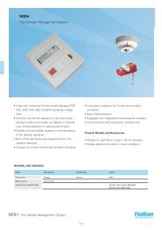
Air quality is becoming a major concern for everyone.<br />
Many kitchens will require emissions control in their<br />
exhaust systems to comply with growing demands for<br />
environmentally-friendly operation.<br />
The Capture Jet ® range of hood systems with Water<br />
Wash provides solutions for a variety of commercial<br />
food service ventilation applications over virtually<br />
any cooking process. Based on <strong>Halton</strong>’s patented<br />
highly efficiency Capture Jet ® solution and advanced<br />
mechanical KSA filter technology, the hot water wash<br />
down is especially suited for facilities with cooking<br />
operation producing substantial volumes of grease and<br />
requires reduce reduced maintenance.<br />
• Improved indoor air quality with reduced energy<br />
use. <strong>Halton</strong> Capture Jet ® technology reduces<br />
the exhaust airflow rates required and improves<br />
the capture and containment efficiency of the<br />
hood.<br />
• Automatic Water Wash features allow for<br />
continuous operation without extended shut<br />
down for cleaning.<br />
• High efficiency grease filtration using UL and<br />
NSF classified <strong>Halton</strong> KSA multi-cyclone filters<br />
with a particulate extraction efficiency of 92%<br />
on particles with a diameter of 8 microns per<br />
ASTM F2519.<br />
• Standard with LED lighting and T.A.B. (testing and<br />
balancing) ports, which allow accurate and effective<br />
commissioning.<br />
• AccuFlow provides a visual indicator that the<br />
system is at design exhaust air values at the face of<br />
the hood. A pressure transducer measures design<br />
exhaust rate and provides a green indicator light.<br />
• Standard incandescent globe type light fixture(s).<br />
• UL Listed control panel for water wash cycle.<br />
• Stainless steel, welded design.<br />
NOTE: Factory must be advised of any special requirements of the<br />
Authority Having Jurisdiction at time of quote.<br />
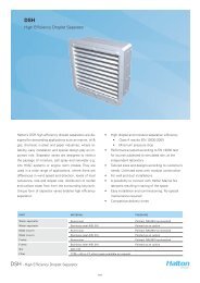
<strong>KVC</strong>-<strong>WW</strong> - Capture Jet ® Hood with Supply Air and Water Wash<br />
1
4 5<br />
8<br />
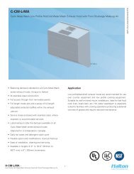
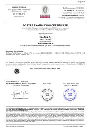
Part<br />
Description<br />
<strong>KVC</strong>-<strong>WW</strong>/PC/xxxx11507/EN<br />
6<br />
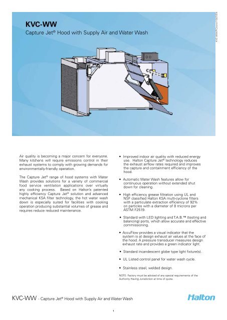
1 18 Ga. stainless steel<br />
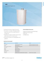
2 Integrated supply air plenum<br />
1<br />
3<br />
7<br />
3 Capture Jet air<br />
4 Double wall construction<br />
2<br />
5 Light fixture<br />
6 KSA grease filter<br />
7 Drain nozzle connection<br />
8 Exhaust duct collar<br />
Construction<br />
The <strong>KVC</strong> hood comprises of Capture Jet ®<br />
technology, airflow measurement T.A.B. ports and<br />
KSA multi-cyclone grease filters. The exposed part<br />
of the hood is made of stainless steel. The joints<br />
of the inner liner have a fully-welded construction.<br />
The hood ends have double side wall construction.<br />
The Capture Jet ® is introduced through a special<br />
discharge panel. Grease extracted by the KSA<br />
multi-cyclone filter. The air flow through the<br />
Capture Jet ® air chamber is determined by<br />
the T.A.B. ports located inside the upper hood<br />
chamber. The Capture Jet ® system is installed in<br />
a plenum, which has been studied in detail using<br />
computational fluide dynamics (CFD) to ensure<br />
optimum results.<br />
The exposed parts are manufactured from 18 ga.<br />
DIMENSIONS<br />
<strong>KVC</strong>-<strong>WW</strong><br />
inches<br />
Length 48....168<br />
Width 48....84<br />
Height 30<br />
QUICK DATA<br />
Length Recommended Exhaust air volumes Recommended Capture Jet air volumes<br />
48....168 * Actual exhaust air volumes are calculated by using<br />
the heat load based design method utilizing the <strong>Halton</strong><br />
H.E.L.P. (Hood Engineering Layout Program)<br />
*Average operating range from light to to heavy duty<br />
cooking loads 135 cfm to 275 cfm per linear foot<br />
Capture Jet average pressure 0.40” WC<br />
(without Side Jet option).<br />
*Airflows established by a pressure reading<br />
*WC= Water Column<br />
*Hoods are UL listed for USA per UL710, and CANADA per ULC-S646 standards, and NSF certified.<br />
<strong>KVC</strong>-<strong>WW</strong> - Capture Jet ® Hood with Supply Air and Water Wash<br />
2
<strong>KVC</strong> -<strong>WW</strong>-UV/xxxx/011507/EN<br />
C<br />
E<br />
B<br />
A<br />
D<br />
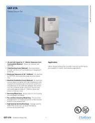
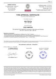
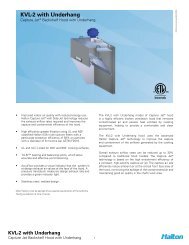
Heat spilling<br />
Capture &<br />
containment<br />
Function<br />
The kitchen hood above cooking appliances contains<br />
the rising warm air and contaminants (A). The capture<br />
air jets (B) direct the contaminated air toward the KSA<br />
grease filters (C), where grease particles and other<br />
impurities are separated from the exhaust air using the<br />
cyclone separation principle. The extracted grease and<br />
other air contaminants flow into a drain channel and<br />
toward the collection tray (D).<br />
Make up air is distributed into the space at low velocity<br />
through the front plenum of the hood (E). The vertical<br />
capture air improves efficiency, and allows the hood<br />
to operate at lower exhaust airflows. Capture Jet air<br />
is used to increase air velocity in the working zone<br />
near the cooking equipment in order to compensate<br />
for the effects of radiant heat emitted by the cooking<br />
equipment.<br />
Accessories<br />
• Closure Panels - for hoods below ceiling level<br />
• Backsplash<br />
• Side Skirts (optional)<br />
• Recessed fluorescent<br />
• Recessed incandescent<br />
• Incandescent globe type lights<br />
• MEP - Master Electrical Panels<br />
• Face or remote mounted switch panels<br />
• Factory prepiped Fire Protection<br />
• Powder Coated<br />
• Listed Exhaust Duct Balancing Damper<br />
• Custom/Designer Stainless Steel Exterior Textures<br />
• Hood Mounted Fire Cabinet<br />
• M.A.R.V.E.L. Demand Control w/ VFD by <strong>Halton</strong><br />
Wiring diagram<br />
Supplemental instructions are included in shipment<br />
packing, detailing the job specific electrical wiring<br />
requirements for the control panel(s) and hood(s). If<br />
these cannot be found, please contact the factory prior<br />
to any electrical work.<br />
<strong>KVC</strong>-<strong>WW</strong> - Capture Jet ® Hood with Supply Air and Water Wash<br />
3
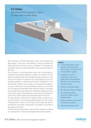
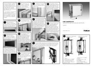
DIMENSIONS<br />
KVE-<strong>WW</strong> - Wall model inches<br />
Length 48....168<br />
Width<br />
52....84 (including 3” standoff)<br />
3” (76)<br />
TOP<br />
INTAKE (OPTIONAL)<br />
SPEED<br />
CONTROLLER<br />
FRONT<br />
INTAKE<br />
(STD)<br />
S.S. PERF<br />
<strong>KVC</strong>-<strong>WW</strong>/PC/xxxx11507/EN<br />
Height 30<br />
WATER<br />
MANIFOLD<br />
TAB<br />
PORTS<br />
S.S. KSA<br />
FILTERS<br />
ACCESS<br />
DOOR<br />
LOW VELOCITY<br />
DISCHARGE<br />
DRAIN<br />
CAPTURE JET AIR<br />
8.5”<br />
(216)<br />
Noted in drawings as:<br />
* L = Length<br />
* W = Width<br />
* H = Height<br />
WEIGHTS (LB)<br />
18 ga.<br />
3”<br />
(76)<br />
W<br />
7”<br />
(178)<br />
Estimated Crated<br />
Shipping Weight<br />
inches<br />
Weight<br />
TOP<br />
INTAKE<br />
(OPTIONAL)<br />
Width 48” 80 lbs / lin.ft.<br />
Width 54” 85 lbs / lin.ft.<br />
L<br />
FRONT<br />
INTAKE<br />
(STD)<br />
Width 60” 90 lbs / lin.ft.<br />
CONNECTION<br />
FOR LIGHTS<br />
&<br />
CJ FAN<br />
*Larger Weights - Consult Factory<br />
Mounting bracket 2” high (52mm)<br />
TOP<br />
3” (76)<br />
SPEED<br />
CONTROLLER<br />
INTAKE (OPTIONAL)<br />
FRONT<br />
INTAKE<br />
(STD)<br />
S.S. PERF<br />
WATER<br />
MANIFOLD<br />
TAB<br />
PORTS<br />
S.S. KSA<br />
FILTERS<br />
ACCESS<br />
DOOR<br />
2”<br />
LOW VELOCITY<br />
DISCHARGE<br />
DRAIN<br />
CAPTURE JET AIR<br />
8.5”<br />
(216)<br />
<strong>KVC</strong>-<strong>WW</strong> - Capture Jet ® Hood with Supply Air and Water Wash<br />
4
<strong>KVC</strong> -<strong>WW</strong>-UV/xxxx/011507/EN<br />
C<br />
A<br />
D<br />
D<br />
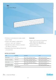
KSA Filter<br />
F<br />
G<br />
B<br />
E<br />
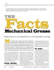
Item<br />
Description<br />
A<br />
B<br />
C<br />
D<br />
E<br />
F<br />
G<br />
Capture Jet Fan Access<br />
A multi-cyclone KSA extractor<br />
Water Wash Intake Supply<br />
Water Wash Nozzle Manifolds<br />
Drain Pipe Connection<br />
Safety Switches<br />
Integrated Supply Air Plenum<br />
<strong>KVC</strong>-<strong>WW</strong> - Capture Jet ® Hood with Supply Air and Water Wash<br />
5
Suggested specifications<br />
General<br />
Kitchen hood inner liner shall be constructed from 18 gauge<br />
stainless steel where exposed. The kitchen hoods shall be<br />
supplied complete with outer casing/main body, inner<br />
liner, exhaust duct, pressure measurement T.A.B. ports.<br />
Outer casing panels shall be constructed of stainless steel<br />
with a brushed satin finish. Each joint shall be welded and<br />
liquid tight.<br />
All exposed welds are ground and polished to the original<br />
finish of metal. Canopy ends shall be double sided wall<br />
construction (no single wall hoods permitted).<br />
Exhaust<br />
The exhaust airflow will be based on the convective heat<br />
generated by the appliances underneath each hood system.<br />
Submittals shall include convective heat calculations based<br />
on the input power of the appliance served.<br />
Capture Jet ® System<br />
The hood shall be designed with Capture Jet ® technology<br />
to reduce the exhaust airflow rate required, and to improve<br />
the capture and containment efficiency of the hood, while<br />
reducing energy consumption. The Capture Jet ® air shall be<br />
introduced through a special discharge panel and shall not<br />
exceed 10% of the calculated exhaust airflow. The Capture<br />
Jet ® discharge velocity will be a minimum of 1500 feet per<br />
minute. Slot or grille type discharge shall not be used.<br />
The Capture Jet ® shall be internally mounted with a speed<br />
control and will not require a fire damper or electronic shut<br />
down in fire mode.<br />
Supply Air Plenum<br />
The integral front discharge make up air plenum shall<br />
be manufactured of the same material as the hood. The<br />
face of the plenum will be perforated stainless steel to<br />
deliver low velocity air to the space and to minimize room<br />
turbulence while refreshing the occupied zone.<br />
Motor Starter<br />
Motor starter with overload protection will be provided for<br />
each fan motor supplied by <strong>Halton</strong>.<br />
Water Wash<br />
The hood shall include three full length wash manifolds<br />
equipped with brass spray nozzles. When the wash cycle<br />
is initiated, the exhaust fan shall shut off. The wash sprays<br />
shall come on for the length of time programmed in the<br />
control panel. The two forward manifolds shall wash the<br />
interior and exterior of the grease extractor. All controls<br />
and components for operation of the water wash system<br />
shall be housed in the Ventilator Control Cabinet.<br />
T.A.B. Ports<br />
The airflows through the extractors and the Capture Jet ® air<br />
chamber are to be determined through the integral T.A.B.<br />
(Testing and Balancing) ports mounted in the hood. The<br />
airflows are to be determined by the pressure vs. airflow<br />
curves supplied by <strong>Halton</strong>.<br />
AccuFlow<br />
The Capture Jet hood will come standard with the<br />
<strong>Halton</strong> AccuFlow indicator. The AccuFlow provides a<br />
visual indicator that the system is at design exhaust<br />
air values. A pressure transducer measures design<br />
exhaust rate and this is interpreted by the AccuFlow<br />
sensor by a steady green indicator light. Should the<br />
system be below design airflow, the indicator light will<br />
blink once in sequence. Should the indicator light blink<br />
twice in sequence, the exhaust airflow is above design.<br />
Light Fixtures<br />
Hood lights shall be U.L. Listed LED fixtures, suitable for<br />
grease hoods. 20 Watts per fixture, 50 foot candles at<br />
cooking surface. Option: Recessed fluorescent, recessed<br />
incandescent or incandescent globe type lighting. The<br />
lighting shall be suitable for single phase power supply.<br />
Control Panel<br />
The master electrical panel consisting of one starter per<br />
motor with overload protection can be supplied (optional).<br />
Control panel to hood or remote mounted.<br />
Grease Extractors<br />
The hood shall be equipped with KSA multi-cyclone<br />
stainless steel grease extractors. The KSA filters shall be<br />
NSF and UL classified. The particulate extraction efficiency<br />
is 70% on particles with a diameter of 5 microns and 98%<br />
on particles with a diameter of 15 microns per ASTM F2519.<br />
The pressure loss over the extractor shall not exceed 0.70<br />
inches W.C. at flow rates approved by UL for heavy load<br />
cooking. Sound levels shall not exceed an NC rating of 55.<br />
Baffle or slot type extractors shall not be used.<br />
Fire Suppression System<br />
The kitchen hood fire extinguishing system shall protect<br />
the kitchen hood against grease fires by a completely<br />
automatic fire control system, which consists of wet<br />
chemical. The fire detection system shall be capable of<br />
detecting fire in the hood, duct, or surface equipment and<br />
shall automatically discharge liquid extinguishing agent<br />
into the plenum chamber, exhaust duct collar, and cooking<br />
appliance areas to ensure against re-ignition or re-flash.<br />
System components shall include a spring-loaded fusible<br />
link detector, wall mounted emergency pull stations, wall<br />
mounted automan and cabinet, and a mechanical gas valve<br />
installed in the gas line serving the cooking equipment.<br />
System installation shall be made by an authorized<br />
representative of the system manufacturer and conform<br />
to UL 300 requirements and local codes.<br />
.<br />
<strong>KVC</strong>-<strong>WW</strong>/PC/xxxx11507/EN<br />
<strong>KVC</strong>-<strong>WW</strong> - Capture Jet ® Hood with Supply Air and Water Wash<br />
6