Control Unit - Harvia
Control Unit - Harvia
Control Unit - Harvia

You also want an ePaper? Increase the reach of your titles
YUMPU automatically turns print PDFs into web optimized ePapers that Google loves.
FI<br />
EN<br />
<strong>Control</strong> <strong>Unit</strong><br />
<br />
11012007
CONTENTS<br />
EN<br />
EN<br />
FENIX WIRELESS CONTROL UNIT................... 3<br />
QUICK GUIDE............................................... 4<br />
FIRST SWITCH-ON....................................... 4<br />
CHOOSING THE PANEL LANGUAGE............... 4<br />
SETTING THE TIME AND DAY........................ 4<br />
CONNECTIONS BETWEEN DEVICES................ 4<br />
DEVICE PAIR-UP........................................... 4<br />
HEATING UP THE SAUNA............................. 5<br />
SETTING THE PRE-SETTING TIME -<br />
delayed heating............................................ 5<br />
1. HARVIA FENIX CONTROL UNIT.................. 6<br />
1.1. General............................................. 6<br />
1.2. Technical Data................................... 6<br />
1.3. Configurations.................................... 7<br />
2. INSTRUCTIONS FOR USE.......................... 7<br />
2.1. General............................................. 7<br />
2.1.1. Batteries.................................. 7<br />
2.2. Function Menus in the Main Menu<br />
and Function Icons.................................... 7<br />
2.3. Sauna Time Setup.............................. 8<br />
2.4. Heater and Steamer Setup................... 8<br />
2.4.1. Heater Setup............................ 8<br />
2.4.2. Steamer Setup.......................... 8<br />
2.5. Colour Light and Light Setup.............. 10<br />
2.5.1. Colour Light Setup.................. 10<br />
2.5.2. Light Setup............................ 11<br />
2.6. Fan Setup........................................ 11<br />
2.7. Week Timer .................................... 12<br />
2.8. User Settings................................... 13<br />
2.9. Miscellaneous.................................. 14<br />
2.9.1. Statistics............................... 14<br />
2.9.2. Curve Diagram........................ 14<br />
2.9.3. Adjust Current Time and Day.... 14<br />
2.9.4. Device Pair-Up........................ 14<br />
2.9.5. Panel Power Settings............... 15<br />
2.9.6. Additional Options and Settings 15<br />
2.9.7. Detailed Version Info............... 15<br />
2.9.8. Sensor Reading Adjustment...... 15<br />
2.9.9. Service Menu......................... 15<br />
a) Auxiliary Relay Function................. 15<br />
b) Installed/Enabled Features.............. 15<br />
c) Heater Watts Setup....................... 15<br />
d) Steamer Watts Setup.................... 15<br />
e) Max On Time Setup...................... 15<br />
f) Load Factory Settings.................... 15<br />
2.10. Options......................................... 15<br />
2.10.1. Calibrating the Touch Screen.. 16<br />
3. INSTRUCTIONS FOR INSTALLATION......... 18<br />
3.1. Installing the Wireless <strong>Control</strong> <strong>Unit</strong>...... 18<br />
3.2. Installing the Power <strong>Unit</strong>.................... 20<br />
3.2.1. Electrical Connections of Power<br />
<strong>Unit</strong> SACF150 for Heater................... 20<br />
3.2.2. Electrical Connections of Power<br />
<strong>Unit</strong> SACF165S for Steamer/Heater.... 20<br />
3.2.3. Electrical Installations of Power<br />
<strong>Unit</strong> SACF100 for Colour Light........... 20<br />
3.2.4. Installing the Radio Antenna..... 26<br />
3.2.5. Installing the Temperature<br />
and Humidity Sensors....................... 26<br />
3.2.6. Resetting the Overheat<br />
Protector......................................... 27<br />
Congratulations on choosing a Fenix control unit by <strong>Harvia</strong>!<br />
With Fenix you can control all functions of your sauna via the userprompting<br />
touch screen of a wireless control unit. You can control<br />
the temperature, humidity, colour lights, and all other aspects – from<br />
your couch. A novelty that makes it possible for you to enjoy your<br />
sauna in a variety of new ways!
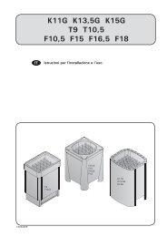
FENIX WIRELESS CONTROL UNIT<br />
(The displayed view varies according to the features acquired and enabled.)<br />
Fitting and changing the batteries to the<br />
wireless control unit, behind the display<br />
Power switch ON/OFF<br />
Active functions<br />
Time setting<br />
Removing<br />
the cover<br />
EN<br />
Function icons<br />
Replacing<br />
the cover<br />
Touch screen of<br />
the wireless control unit<br />
Start Menu<br />
(The displayed view varies according to the features acquired and enabled.)<br />
Function Icons<br />
Light ON/OFF<br />
Sauna ON/OFF<br />
Fan ON/OFF<br />
Colour Light<br />
ON/OFF<br />
Set the Pre-Setting Time<br />
Main Menu<br />
Heater ON/OFF<br />
Steamer ON/OFF<br />
Function ON<br />
Function OFF<br />
Under the Sauna ON/OFF icon you’ll find information on the conditions in your sauna, offering short cuts to<br />
change the settings affecting the current sauna bath.<br />
The icons in the top row<br />
provide short cuts to active<br />
functions, for example<br />
Colour Light Settings.<br />
Short cut to Temperature<br />
Settings.<br />
Short cut to Graph View.<br />
Short cut to Weekday<br />
and Time Settings.<br />
Sauna OFF<br />
The icon in the upper right corner<br />
indicates the power source<br />
(batteries or charger). It does not<br />
indicate what the charge level is<br />
or when charging is required.<br />
Short cut to Steamer Settings.<br />
Short cut to Operating Time<br />
Settings.<br />
To the Main Menu by pressing the<br />
function icon<br />
In Sauna ON mode, you can also<br />
switch to Main Menu by pressing the<br />
power switch lightly. The link to the<br />
Main Menu appears on the screen.
Main Menu - Function Menus<br />
(The displayed view varies according to the features acquired and enabled.)<br />
EN<br />
Main Menu, page 1 Page change Main Menu, page 2<br />
<strong>Control</strong>s in Menus<br />
Back to the Start Menu<br />
Confirm<br />
Exit/Cancel<br />
Arrow<br />
icons<br />
Track<br />
bar<br />
QUICK GUIDE<br />
FIRST SWITCH-ON<br />
First time when you switch on the wireless control unit, it will automatically prompt you to calibrate the<br />
touch screen. The unit will guide you through the calibration process. After this you need to choose the<br />
desired panel language and set the day and time. Make the required settings and confirm. If the unit does<br />
not follow the above steps automatically, they can be carried out manually:<br />
CALIBRATING THE TOUCH SCREEN (see section 2.10).<br />
CHOOSING THE PANEL LANGUAGE<br />
1. Start Menu (the first menu to appear after switching on).<br />
2. Press the Main Menu icon. Use the page change to scroll through the Main Menu to<br />
User Settings and select.<br />
3. Use the page change to scroll to Panel Language and select.<br />
4. Choose a language and Confirm.<br />
5. Press the Exit icon to return to the Start Menu.<br />
SETTING THE TIME AND DAY<br />
1. Press the Main Menu icon. Use the page change to scroll through the Main Menu to Miscellaneous and select.<br />
2. Use the page change to scroll to Adjust current time and select.<br />
3. Set day and confirm.<br />
4. Set time and confirm.<br />
CHOOSING THE DEVICES TO BE ENABLED (see Service menu 2.9.9. b).<br />
CONNECTIONS BETWEEN DEVICES<br />
An icon in the upper left corner of the screen indicates whether<br />
the connections are active or whether there are lost connections<br />
or new devices to be connected. When connections are lost it can<br />
also be a case that the wireless control unit is outside the operating<br />
range (ca. 10 m) of the radio link.<br />
Missing connections are established through device pair-up. See<br />
the following quick tips or chapter 2.9.4. ‘Device Pair-Up’ (further<br />
below).<br />
Connection active – this<br />
icon is displayed while the<br />
devices are communicating<br />
with each other.<br />
No connection – this icon<br />
is constantly displayed<br />
while the connections are<br />
disconnected.
DEVICE PAIR-UP<br />
The following pair-up procedure is necessary to make the devices recognize each other and communicate:<br />
1. Switch on the wireless control unit. The Start Menu is displayed.<br />
2. Press the Main Menu icon. Use the page change to scroll through the Main Menu to Miscellaneous and select.<br />
3. Use the page change to scroll to Device Pair-Up and select. This is the procedure to be used to<br />
establish a connection between devices/device pairs.<br />
4. Under the selected menu item you will find the pair-up procedure menu. When you are establishing<br />
connections between device pairs for the first time, select Help. Read through the instructions and<br />
follow them.<br />
5. Press the Confirm icon to switch back to the Pair-Up Procedure menu:<br />
EN<br />
Pair-Up Procedure<br />
Pair-Up Help, page 1 Pair-Up Help, page 2<br />
A) Click ’New code’, and the display will show ‘ Panel code changed.<br />
Renewing pairs is necessary.’<br />
C) Click ’Heater’, and the display will show ‘Linking to Heater,<br />
switch power on now.’<br />
D) Turn power unit on within 10 seconds, and the display will show ‘Successful pair-up with heater.’<br />
If the pairing up was not successful, the display will show “Pair-up with heater FAILED”. In this<br />
case, return to Step B and repeat the procedure according to the<br />
instructions.<br />
6. To further add colour light, for example, press ‘Colour light’.<br />
NOTE! If you press the ‘New Code’ icon again, all connections are lost<br />
and must be re-established!<br />
Pair-Up icon for heater<br />
power unit<br />
Pair-Up icon for colour<br />
light power unit<br />
HEATING UP THE SAUNA<br />
1. Start Menu (the first menu to appear after switching on).<br />
2. Use the function icons to switch functions on or off.<br />
Light ON/OFF, Sauna ON/OFF, Heater ON/OFF, Steamer ON/OFF (model SACF165S)<br />
While an icon is activated, the corresponding function is on.<br />
The display shows up-to-date information on your sauna, including the temperature, humidity and<br />
remaining operating time.<br />
3. All displayed data can be changed. Go to settings by pressing the relevant reading or the icon up on<br />
the screen. Make the desired changes and confirm or cancel to return to the previous screen. Any<br />
confirmed changes only affect the current bath.<br />
4. When active icons are deactivated, the corresponding functions are switched off, and the display will<br />
show a recap of the most recent sauna bath, including the total time and energy consumption. Touch<br />
the screen to return to the Start Menu.<br />
SETTING THE PRE-SETTING TIME - delayed heating<br />
1. Press the Set the Pre-Setting Time icon.<br />
2. Set the desired Delay after which the heater should start heating up the sauna. Use the arrow<br />
icons, which enable an accurate setting, or the track bar.<br />
3. Confirm by pressing the Sauna ON icon or cancel if you wish to make other settings. This takes<br />
you back to the Start Menu.<br />
4. While the function is activated, the display shows up-to-date information on your sauna,<br />
including the temperature, humidity and remaining time to heating. Activate from the current<br />
display Heater ON and/or Steamer ON, depending for which function you wish to<br />
set the pre-setting<br />
time.<br />
5. To activate other functions, press the displayed function icons, for example Light ON.
EN<br />
1. HARVIA FENIX CONTROL UNIT<br />
1.1. General<br />
<strong>Harvia</strong> Fenix is a multidimensional control unit that<br />
makes it possible for you to enjoy your sauna in a<br />
wider variety of ways. The Fenix control unit allows<br />
you to totally control your sauna and the bathing<br />
conditions, such as the temperature, humidity and<br />
ventilation.<br />
The control unit consists of a wireless control<br />
unit (touch screen), a power unit/power units and<br />
a sensor/sensors. The touch-screen control unit<br />
communicates with the power unit wirelessly or,<br />
alternatively, via a cable. See Figure 1.<br />
The control unit can be used to control sauna<br />
heaters and Combi combined heaters/steamers within<br />
an output range of 2,3–15 kW. The Fenix wireless<br />
control unit operates to a distance of about 10<br />
metres from the power unit, depending on structural<br />
obstacles.<br />
1.2. Technical Data<br />
Wireless control unit:<br />
• Touch screen for controlling the sauna by selecting<br />
the desired functions and settings. Equipped with<br />
rechargeable batteries. The recharge stand must<br />
be placed in a dry place outside the sauna room.<br />
See Figure 2.<br />
• Operating voltage 3,6 V.<br />
• Temperature adjustment range 40–110 °C.<br />
•<br />
•<br />
•<br />
•<br />
•<br />
•<br />
•<br />
Humidity adjustment range 20–95 % RH.<br />
Operating time adjustment range:<br />
family saunas 0,5–6 h, no week timer<br />
public saunas in apartment buildings 0,5–12<br />
h, required pause time min. 6 h.<br />
For longer operating times consult the<br />
importer/manufacturer.<br />
Pre-setting time adjustment range 0–18 h.<br />
Programmable week timer.<br />
Lighting control, max. power 100 W,<br />
230 V 1N~<br />
Fan control, max. power 100 W, 230 V 1N~<br />
Colour light control, max. power 2 x 50 W colour<br />
light unit 12 V DC.<br />
Power units:<br />
•<br />
•<br />
•<br />
Supply voltage 400 V 3N~<br />
Max. load 15 kW/400 V 3N~<br />
The power units are placed in a dry place outside<br />
the sauna room. They must not be embedded<br />
within the wall structure.<br />
Sensors:<br />
•<br />
The temperature sensor is equipped with a<br />
resettable overheat protector and a temperaturesensing<br />
NTC thermistor. The sensor is installed<br />
in the sauna room according to the instructions<br />
given in chapter 3.2.5. ‘Installing the Temperature<br />
and Humidity Sensors’.<br />
The humidity sensor measures relative humidity.<br />
The sensor is installed in the sauna room<br />
according to the instructions given in chapter<br />
3.2.5. ‘Installing the Temperature and Humidity<br />
Sensors’.<br />
•<br />
Figure 1. Interconnected devices of a Fenix control unit.
1.3. Configurations<br />
The <strong>Harvia</strong> Fenix control unit consists of different<br />
devices which together allow comprehensive control<br />
over all aspects of sauna bathing. Available device<br />
packages are:<br />
SACF10 wireless control unit for controlling power<br />
units, incl.<br />
• Touch screen (wireless control unit)<br />
• Recharge stand<br />
• Wall-mounting plate for recharge stand<br />
• Charger<br />
• 3 AA rechargeable batteries<br />
• Instructions for installation and use.<br />
SACF150 power unit for controlling heater (max.<br />
15 kW), incl.<br />
• Power unit SACF150 for heater control<br />
• Radio antenna and cable for communication with<br />
wireless control unit<br />
• Temperature sensor<br />
• Humidity sensor (available as an accessory)<br />
SACF165S power unit for controlling combined<br />
heater/steamer (max. 16,5 kW), incl.<br />
• Power unit SACF165S for heater/steamer<br />
control<br />
• Radio antenna and cable for communication<br />
with wireless control unit<br />
• Temperature sensor<br />
• Humidity sensor<br />
SACF100 power unit for controlling colour light,<br />
incl.<br />
• Power unit SACF100 for controlling colour light<br />
units max. 2 x 50 W<br />
• Cable for connection to power unit SACF150<br />
or SACF165S<br />
2. INSTRUCTIONS FOR USE<br />
Before you switch the heater on check always that<br />
there aren’t any things over the heater or in the near<br />
distance of the heater.<br />
2.1. General<br />
The wireless control unit is equipped with a userprompting<br />
touch screen and is operated by three<br />
AA rechargeable batteries. The unit comes with a<br />
recharge stand. The recharge stand can be mounted<br />
into the wall or to the table but it must be placed<br />
outside the sauna room. Never take the wireless<br />
control unit to a heated sauna!<br />
The wireless control unit is activated by pressing the<br />
black power switch above the screen. Activation brings<br />
the Start Menu with the function icons to the screen.<br />
Pressing a function icon switches the corresponding<br />
function on or off. Activated functions are indicated<br />
by a dark spot in the corner of relevant function icons<br />
and by ‘active function’ images above the screen.<br />
The touch screen can be operated using a finger<br />
or, for example, the blunt end of a pencil. Avoid<br />
pressing the screen unnecessarily hard!<br />
Clean the touch screen from time to time with a<br />
cloth or mild alcohol wipe.<br />
2.1.1. Batteries<br />
The instructions for fitting/changing the batteries can<br />
be found on page 59. The Fenix wireless control unit<br />
comes with NiMh AA HR6 rechargeable batteries,<br />
voltage 1,2 V. The rechargeable batteries can be<br />
replaced with non-rechargeable AA batteries. Note!<br />
Never place the wireless control unit in the recharge<br />
stand when fitted with non-rechargeable batteries. Do<br />
not use rechargeable and non-rechargeable batteries<br />
simultaneously together.<br />
New, unused batteries must be charged uninterruptedly<br />
for 24 hours before use. A complete recharge takes<br />
12 hours. It is recommended to keep the wireless<br />
control unit in the supplied recharge stand when the<br />
unit is not in use – this way the batteries have charge<br />
when the unit is needed again.<br />
Never use a damaged charger or battery. Remove<br />
the damaged battery from the unit. Dispose of the<br />
batteries according to the local regulations (concerning<br />
recycling etc.). Do not place batteries in household<br />
waste. Remove the batteries before disposing of<br />
the unit. Remove the unit from the charger before<br />
fitting/changing batteries.<br />
2.2. Function Menus in the Main Menu and<br />
Function Icons<br />
You can control all functions of your sauna using<br />
the function menus or the function icons.<br />
Function Icons<br />
Light, Fan and Colour Light are activated by pressing<br />
the relevant function icon on the screen.<br />
Sauna ON/OFF<br />
Press the Sauna ON/OFF icon to enable<br />
communication between the power unit and<br />
the wireless control unit. The wireless control<br />
unit now displays information on the conditions<br />
in your sauna, such as temperature and humidity.<br />
Should the connection between the power unit and<br />
the wireless control unit be lost during the bath, the<br />
power unit will nevertheless be able to perform the<br />
programmed functions since all the settings remain<br />
stored in its memory.<br />
Settings (operating time, temperature, humidity<br />
etc.) made in the Sauna ON mode only affect the<br />
current bath.<br />
Settings made in the Sauna OFF mode are default<br />
settings which are stored in the memory of the<br />
wireless control unit.<br />
The Set the Pre-Setting Time icon takes<br />
you directly to the screen where you can<br />
set the pre-setting time.<br />
Pressing the Main Menu icon brings the<br />
function menus to the screen.<br />
Through the Main Menu you can change all the<br />
settings related to your sauna. The function menus<br />
are explained in detail further below.<br />
The pictures shown in this manual are meant as<br />
guidelines only since the screens may vary according<br />
to which features have been acquired and enabled<br />
for use.<br />
Function icons can be added and removed from<br />
the screen. See 2.9.9. ’b) Installed / Enabled<br />
Features’.<br />
<br />
EN
2.3. Sauna Time Setup<br />
Through the Sauna Time Setup menu you can make<br />
timer settings for your sauna.<br />
•<br />
•<br />
The operating time is the time the heater is on.<br />
The pre-setting time is the delay period after<br />
which the heater starts heating up the sauna. Do<br />
not forget to activate Heater ON and/or Steamer<br />
ON icon on the screen, depending for which<br />
function you wish to set the pre-setting time.<br />
EN<br />
From the<br />
Main Menu choose<br />
2.4. Heater and Steamer Setup<br />
2.4.1. Heater Setup<br />
Under the Heater Setup menu you can set the<br />
temperature that the heater is expected to create<br />
in the sauna room.<br />
While the AUTO ON icon is activated, the heater<br />
will switch on automatically when you press the<br />
Sauna ON/OFF icon. To switch on the heater with<br />
the AUTO ON icon deactivated, press the Sauna ON<br />
icon and then activate the Heater ON/OFF icon.<br />
To keep your sauna in a good condition for longer,<br />
it is important that you have it dehumidified after<br />
bathing. With Fenix you can do this by leaving the<br />
heater on for a desired period at a temperature of<br />
40 o C. Once the function is activated, it will stay on<br />
until the setting is changed by the user.<br />
2.4.2. Steamer Setup<br />
The steamer is controlled through the Steamer Setup<br />
menu. One of the two modes must be selected:<br />
1) In the %RH Mode (%RH = relative humidity<br />
expressed as a percentage) the humidity sensor<br />
measures the humidity in the sauna room and the<br />
wireless control unit controls the steamer so that<br />
the humidity level is maintained as close to the set<br />
value as possible during the bath.<br />
Set the desired humidity %RH. The sum of the<br />
steamer %RH setpoint and the max. heater setup<br />
cannot exceed 140.<br />
2) The Interval Mode means that the steamer is<br />
on and off periodically. Set the desired duration of<br />
the two periods: for example the ON period at 140<br />
seconds and the subsequent OFF period at 85 s.<br />
Confirm the settings.<br />
While the AUTO ON icon is activated, the steamer<br />
will switch on automatically when you press the<br />
Sauna ON/OFF icon.
From the<br />
Main Menu choose<br />
EN<br />
ON<br />
OFF<br />
ON<br />
OFF<br />
From the<br />
Main Menu choose
EN<br />
2.5. Colour Light and Light Setup<br />
The colour light settings are available only if your<br />
Fenix control unit is equipped with the colour light<br />
feature. The feature can also be retrofitted.<br />
2.5.1. Colour Light Setup<br />
To activate the colour light in your sauna room, press<br />
the Colour Light function icon. If you wish to change<br />
the colour light settings, choose Colour Light Setup<br />
from the Main Menu.<br />
Colour Light Menu:<br />
There are four colours to choose from: blue, red,<br />
green, and yellow. You can choose just one colour<br />
or cycle all the four colours.<br />
1) To cycle the colours, set the cycle speed<br />
determining how long each colour is on at slow,<br />
medium, or fast.<br />
2) To use just one colour, press Change Colour to<br />
choose the desired colour. The colour that is left<br />
displayed will stay on.<br />
The Set Brightness icon is used to adjust the<br />
brightness of the colour light.<br />
While the AUTO ON icon is activated, the colour<br />
light will switch on automatically when your sauna<br />
is ready for bathing.<br />
While the AUTO OFF icon is activated, the<br />
colour light will switch off automatically after the<br />
desired delay period, which can be set at max. 90<br />
minutes.<br />
Colour Light <strong>Unit</strong> Disabled indicates whether the<br />
colour light is in use or not.<br />
From the<br />
Main Menu choose<br />
disabled<br />
enabled<br />
10
2.5.2. Light Setup<br />
To activate the lighting of your sauna, press the<br />
Light icon in the Start Menu. If you wish to change<br />
the light settings, choose Light Setup from the Main<br />
Menu.<br />
From the<br />
Main Menu choose<br />
Light Menu:<br />
While the AUTO ON icon is activated, the lights will<br />
switch on automatically when your sauna is ready<br />
for bathing.<br />
While the AUTO OFF icon is activated, the lights<br />
will switch off automatically after the desired delay<br />
period, which can be set at max. 90 minutes.<br />
EN<br />
2.6. Fan Setup<br />
To activate the fan of your sauna, press the Fan icon<br />
in the Start Menu. If you wish to change the fan<br />
settings, choose Fan Setup from the Main Menu.<br />
Ventilation Menu:<br />
The fan can be set to switch on or off automatically.<br />
From the<br />
Main Menu choose<br />
While the AUTO ON icon is activated, the fan will<br />
switch on automatically when your sauna is ready<br />
for bathing.<br />
While the AUTO OFF icon is activated, the fan will<br />
switch off automatically after the desired delay period,<br />
which can be set at max. 90 minutes.<br />
If you activate the Interval Mode, the fan will be on<br />
and off periodically. Make the necessary ON and OFF<br />
settings: for example, set the fan to blow air into the<br />
sauna room for a period of 60 seconds (ON) and to<br />
switch OFF for the subsequent 60 s.<br />
Delay, for<br />
example<br />
25 min<br />
11
EN<br />
2.7. Week Timer<br />
Electrical safety regulations allow the week timer<br />
feature to be used only in community saunas!<br />
The week timer settings allow you to program a<br />
weekly schedule, which is especially handy if you<br />
use your sauna regularly every week. Set the desired<br />
bathing time for any chosen day – or even every<br />
day – of the week.<br />
When the weekly schedule starts, the wireless<br />
control unit will be activated even if switched off.<br />
A pause of at least 6 h is required between each<br />
two periods created for the Week Timer schedule.<br />
Week Timer Menu:<br />
Choose Enable Program to activate all created<br />
programs to be run at set times.<br />
View Schedule brings to the screen a recap of your<br />
weekly schedule if you have created one; if you<br />
do not have one, the display shows ‘Week timer<br />
program is empty’. You can also change the schedule<br />
in this menu.<br />
Create New Program Timing<br />
• Set the program start time, which is the time you<br />
wish to start bathing. Confirm or, if you wish to<br />
return to the previous screen, cancel.<br />
• Set the program ending time and confirm or<br />
cancel.<br />
• Set the day(s). You can set more than one day<br />
at the same time.<br />
• Confirm the settings or press Cancel to return<br />
to the previous screen.<br />
• Set the desired temperature for the programmed<br />
period.<br />
• Set the desired humidity level for the programmed<br />
period. Make sure you have the Enable Steamer<br />
box ticked.<br />
• Confirm the settings or press Cancel to return<br />
to the previous screen.<br />
The display now shows a recap of the settings<br />
made. Confirm or press Cancel to return to the<br />
previous screen.<br />
If you choose View Schedule again after<br />
programming, the displayed week timer schedule<br />
will contain the period you just programmed. Here<br />
you can change the schedule or, for example, remove<br />
a schedule without deleting it permanently, meaning<br />
that it will remain stored in the memory for later<br />
activation. You can also add/create new schedules.<br />
See the following pages for examples.<br />
Delete All Periods deletes all the periods created for<br />
a week timer schedule. If you choose this option, the<br />
display will show a message asking you to confirm<br />
that you wish to delete all periods. Confirm or cancel<br />
as required.<br />
Check Validation checks the status of the Week<br />
Timer schedule and displays any possible problems<br />
on the screen.<br />
•<br />
•<br />
•<br />
•<br />
•<br />
Heating periods: checks the heating period length<br />
to make sure the max. operating time is not<br />
exceeded.<br />
Resting periods: checks that the pauses in the<br />
Week Timer schedule are at least 6 h.<br />
Periods enabled: displays the activated periods<br />
of the weekly schedule.<br />
Master enable: on / off.<br />
Check progress: indicates the stage of the<br />
check.<br />
From the<br />
Main Menu choose<br />
ON<br />
OFF<br />
12
Press the Page Change icon to move to the next page.<br />
ATTENTION!<br />
Required 6 h<br />
resting time<br />
between<br />
programs does<br />
not come true.<br />
Number<br />
indicates the<br />
amount of errors<br />
in the week<br />
program.<br />
EN<br />
Exit/Cancel<br />
Change<br />
Confirm/Next<br />
Mon, Tue, Wed,<br />
Thu, Fri<br />
Sat, Sun<br />
Steamer enabled<br />
13
To change or delete a created Week Timer period<br />
one at a time, choose View Schedule.<br />
EN<br />
Scroll through periods<br />
Recap of the period(s)<br />
Scroll through periods<br />
Activate period<br />
Return/Cancel<br />
New period<br />
Make changes<br />
Delete period<br />
2.8. User Settings<br />
Through the User Settings menu you can control<br />
settings related to the use of the wireless control<br />
unit.<br />
User Settings Menu:<br />
Backlight Mode<br />
Alternative modes:<br />
Backlight on while unit is on<br />
Backlight on during baths<br />
2 min switch off delay<br />
30 s switch off delay<br />
10 s switch off delay<br />
Always off<br />
Display Contrast<br />
Increase or decrease the contrast and brightness of<br />
the screen as necessary.<br />
Options<br />
You can adapt the information on the display as<br />
follows:<br />
1) You can replace the digital clock, displayed in the<br />
Start Menu by default, with an analogue clock.<br />
2) You can choose the display to cycle any selected/<br />
activated data, such as energy consumption and/or<br />
heater output, during sauna baths. The informative<br />
screen contains, during sauna baths, a recap of<br />
the selected aspects, such as energy consumption<br />
and/or heater output.<br />
14
Panel Language<br />
Choose the language to be used by the wireless<br />
control unit.<br />
Key Beep Tone<br />
The tone range varies from silent to loud beep.<br />
Audible Notifications<br />
You can choose to hear a notification sound when<br />
your sauna is ready for bathing and/or when a week<br />
timer event becomes active.<br />
2.9. Miscellaneous<br />
2.9.1. Statistics<br />
Pressing the Statistics icon brings to the screen a<br />
recap of the most recent sauna bath (total time and<br />
energy consumption). Before the first bath there is<br />
no data stored in the memory. Touch the screen to<br />
return to the previous screen.<br />
2.9.2. Curve Diagram<br />
The current readings of the temperature and humidity<br />
sensors or the readings taken during the most recent<br />
sauna bath are displayed as a graph.<br />
2.9.3. Adjust Current Time and Day<br />
Set the correct time and day. The clock must be<br />
adjusted for summer/winter time.<br />
2.9.4. Device Pair-Up<br />
This procedure is used to establish a connection<br />
between new devices/device pairs and to re-establish<br />
any lost connections. The icon in the upper left corner<br />
of the Start Menu indicates whether the connections<br />
are active or whether connections are missing.<br />
Connection<br />
active<br />
No<br />
connection<br />
Note! The pair-up procedure is unnecessary if the<br />
wireless control unit is connected to the power unit<br />
with a cable. In this case the wireless control unit<br />
does not need batteries or charging, since the required<br />
operating voltage is supplied from the power unit<br />
through the cable.<br />
EN<br />
Device pair-up<br />
The following pair-up procedure is necessary to make the devices recognize each other and communicate:<br />
1. Switch on the wireless control unit. The Start Menu is displayed.<br />
2. Press the Main Menu icon. Use the page change to scroll through the Main Menu to Miscellaneous and select.<br />
3. Use the page change to scroll to Device Pair-Up and select. This is the procedure to be used to<br />
establish a connection between devices/device pairs.<br />
4. Under the selected menu item you will find the pair-up procedure menu. When you are establishing<br />
connections between device pairs for the first time, select Help. Read through the instructions and<br />
follow them.<br />
5. Press the Confirm icon to switch back to the Pair-Up Procedure menu:<br />
Pair-Up Procedure Pair-Up Help, page 1 Pair-Up Help, page 2<br />
A) Click ’New code’, and the display will show ‘ Panel code changed.<br />
Renewing pairs is necessary.’<br />
C) Click ’Heater’, and the display will show ‘Linking to Heater,<br />
switch power on now.’<br />
D) Turn power unit on within 10 seconds, and the display will show ‘Successful pair-up with heater.’<br />
If the pairing up was not successful, the display will show “Pair-up with heater FAILED”. In this<br />
case, return to Step B and repeat the procedure according to the<br />
instructions.<br />
6. To further add colour light, for example, press ‘Colour light’.<br />
NOTE! If you press the ‘New Code’ icon again, all connections are lost<br />
and must be re-established!<br />
Pair-Up icon for heater<br />
power unit<br />
Pair-Up icon for colour<br />
light power unit<br />
15
EN<br />
2.9.5. Panel Power Settings<br />
Set the desired standby delay period after which the<br />
power to the wireless control unit is switched off.<br />
2.9.6. Additional Options and Settings<br />
Here you can activate a safety option which<br />
automatically switches off the power to the unit<br />
devices if the connections between them are lost.<br />
The factory setting of this feature is ‘deactivated’.<br />
2.9.7. Detailed Version Info<br />
Here you can find information on the software, wireless<br />
control unit, power unit and, if installed, colour light<br />
unit included in the configuration. This information<br />
is needed when you update the software.<br />
2.9.8. Sensor Reading Adjustment<br />
Here you can change the readings of the temperature<br />
sensors (NTC thermistor) and the humidity sensor<br />
from the measured ones. The reading can be corrected<br />
by +/- 10 units. This adjustment is to ensure that<br />
the desired temperature is achieved in the sauna<br />
room. To find out the required correction, measure<br />
the temperature and, if necessary, humidity of the<br />
sauna room using external meters.<br />
Temperature sensor A = the NTC thermistor is in<br />
the same box as the overheat protector.<br />
Temperature sensor B = the NTC thermistor is in<br />
the same box as the humidity sensor.<br />
Humidity sensor = the sensor measuring the<br />
humidity level in the sauna room.<br />
NOTE! Correcting sensor readings do not affect the<br />
operation of the overheat protector. The overheat<br />
protector cuts off the power if the temperature around<br />
it exceeds 150 o C. See chapter 3.2.6. ‘Resetting the<br />
Overheat Protector’.<br />
2.9.9. Service Menu<br />
To enter the Service Menu select Miscellaneous in<br />
the Main Menu. Use the arrow icon to scroll through<br />
to Service Menu. To access the Service Menu, you<br />
must enter service code 6143. The code is fixed and<br />
cannot be changed.<br />
a) Auxiliary Relay Function<br />
Power units SACF150 and SACF165S have a<br />
230 V 1N~ auxiliary output which can be used for<br />
different functions.<br />
Auxiliary Output Setup:<br />
Ventilation Fan: Use the AUX output for controlling<br />
the fan (max. 100 W) of your sauna.<br />
Heating control: Use the AUX output for controlling<br />
the electric heating of the building. The output gives<br />
230 V 1N~ in Sauna ON mode.<br />
Indicator: Use the AUX output for installing an<br />
indicator light (max. 100 W) that tells you when<br />
your sauna is ready for bathing.<br />
b) Installed/Enabled Features<br />
Here you can choose the devices acquired and<br />
enabled. When enabled, they will be displayed as<br />
16
function icons on the touch screen of the wireless<br />
control unit. This way you can also adapt the amount<br />
of data displayed. The features available for selection<br />
are steamer, light, colour light and radio link.<br />
For wireless communication you must have at least<br />
the radio link feature selected, since it enables the<br />
real-time communication between devices.<br />
c) Heater Watts Setup<br />
Here you can enter the output of your heater for the<br />
kWh meter. If you cannot find a suitable option from<br />
the list, enter the output in watts.<br />
d) Steamer Watts Setup<br />
Here you can enter the output of your steamer for<br />
the kWh meter. If you cannot find a suitable option<br />
from the list, enter the output in watts.<br />
e) Max On Time Setup<br />
• Family sauna 4 h, max. 6 h:<br />
Select the max. operating time for the heater.<br />
The week timer feature is not available in family<br />
saunas.<br />
• Public sauna in an apartment building 4 h, 6 h,<br />
max. 12 h, pause time 6 h:<br />
Select the max. operating time for the heater,<br />
the week timer feature is in use. When creating a<br />
weekly schedule, bear in mind that the operating<br />
time must be followed by a 6-hour pause.<br />
• For longer operating times consult the importer/<br />
manufacturer.<br />
f) Load Factory Settings<br />
You can restore the wireless control unit to its factory<br />
settings, which means that all the settings you have<br />
made are returned to the defaults.<br />
During restore there must be connection to the<br />
power unit.<br />
1. From the Main Menu select Miscellaneous.<br />
2. Use the page change to scroll to Service Menu<br />
and select. Enter the service code 6143 and<br />
confirm.<br />
3. Use the page change to scroll through the menu<br />
to Load Factory Settings and select.<br />
4. You are now asked to confirm that you wish to<br />
erase all the settings you have made, returning to<br />
the default settings chosen by the manufacturer.<br />
Confirm to restore the factory settings.<br />
2.10. Options<br />
When you press the power switch lightly in the<br />
Sauna OFF mode, the Options menu appears on the<br />
screen. This menu is a short cut to the following<br />
functions:<br />
Standby mode, for switching the screen to standby<br />
mode and switching off the power.<br />
Sauna on, for switching on the sauna.<br />
Sauna on with delay, for setting the pre-setting time<br />
after which the sauna starts heating up.<br />
Next, takes you the next menu page.<br />
Calibration, see chapter 2.10.1.<br />
Exit menu, takes you back to the Start Menu.<br />
2.10.1. Calibrating the Touch Screen<br />
Calibrate the screen if it stops responding or responds<br />
slowly. When you press the power switch in the<br />
Sauna OFF mode, the Options menu appears on the<br />
screen. To switch from one menu item to another,<br />
press the power switch repeatedly. To perform the<br />
calibration, first switch to Next page. Select a section<br />
by pressing the power switch for a longer time. Select<br />
Recalibrate and perform the calibration according to<br />
the displayed instructions on the screen.<br />
EN<br />
Press the power switch in the Sauna OFF mode<br />
17
3. INSTRUCTIONS FOR<br />
INSTALLATION<br />
EN<br />
The electrical connections of the control unit may only<br />
be made by an authorised, professional electrician and<br />
in accordance with the current regulations. When the<br />
installation of the control unit is complete, the person<br />
in charge of the installation shall pass on to the user<br />
the instructions for installation and use that come<br />
with the unit and shall give the user the necessary<br />
training to use the heater and the control unit!<br />
For an overall view of the <strong>Harvia</strong> Fenix control unit<br />
see Figure 1.<br />
3.1. Installing the Wireless <strong>Control</strong> <strong>Unit</strong><br />
The Fenix wireless control unit comes with a table<br />
recharge stand that can be attached to a table with a<br />
screw. The recharge stand can also be wall mounted<br />
using a separate wall-mounting plate. When installing<br />
the recharge stand, observe the distance to the<br />
nearest socket: the cord measures approximately 1,5<br />
m in length. The wall-mounting plate is fixed to the<br />
wall with three screws, and the recharge stand is<br />
fastened to the plate with two screws. The recharge<br />
stand is installed outside the sauna room, in a dry<br />
place with an ambient temperature of >0 ºC. The<br />
wireless control unit can, if necessary, be attached<br />
to the charger with a screw. See Figure 2.<br />
Check the operating range of the radio link (up<br />
to 10 m from the power unit) when installing the<br />
recharge stand. The range varies according to the<br />
structural obstacles.<br />
The wireless control unit can, alternatively, be<br />
connected to the power unit with a cable. The<br />
required operating voltage is then supplied from<br />
the power unit through the cable and batteries can<br />
not be used. If connected to the power unit with<br />
a cable, the wireless control unit can be fixed to<br />
a wall using a special rear cover designed for wall<br />
mounting (see Figure 3). In this case you do not<br />
need a recharge stand.<br />
When you first switch on the wireless control<br />
unit, it will automatically prompt you to calibrate the<br />
touch screen. The screen will guide you through the<br />
calibration process. After this you are asked to choose<br />
the desired panel language and set the day and time.<br />
Make the required settings and confirm. If the unit<br />
does not follow the above steps automatically, they<br />
can be carried out manually (see Quick Guide).<br />
Before the wireless control unit is taken into use,<br />
the installer shall enable the installed features through<br />
the Service Menu.<br />
To add or remove function icons on the screen:<br />
1. Go to the Main Menu.<br />
2. Use the page change to scroll through to<br />
Miscellaneous and select.<br />
3. Scroll to Service Menu and enter the service<br />
code 6143.<br />
Confirm by pressing<br />
Confirm/Next.<br />
4. Choose Installed/Enabled Features. Here you<br />
can activate the required features, which are<br />
then displayed as function icons on the touch<br />
screen of the wireless control unit.<br />
5. Confirm the settings.<br />
6. Select the desired<br />
function for the auxiliary output and Confirm.<br />
18<br />
Figure 2. Wall mounting of the recharge stand.
Figure 3. Wall mounting of the wireless control unit by means of<br />
a special wall-mounting cover.<br />
EN<br />
1<br />
2<br />
Figure 4. Opening the power unit cover and<br />
mounting the unit to a wall.<br />
19
EN<br />
how to select the desired AUX output function see<br />
chapter 2.9.9. a).<br />
The temperature sensor in the sauna room must<br />
be connected to the SACF150 power unit. You<br />
can also install a humidity sensor, available as an<br />
accessory, for measuring the humidity level in the<br />
sauna. For instructions on how to install the sensors<br />
see chapter 3.2.5.<br />
The electrical connections of the power unit are made<br />
according to Figure 6. For wireless communication,<br />
the power unit must be paired up with the wireless<br />
control unit after installation (see chapter 2.9.4).<br />
Table 1 shows the cable thickness and fuse size,<br />
depending on the heater output, to be used with<br />
the Fenix SACF150 power unit. For more detailed<br />
installation instructions see the instructions for<br />
installation and use for the selected heater model.<br />
Figure 5. Wall mounting of the power unit.<br />
3.2. Installing the Power <strong>Unit</strong><br />
The power unit of the <strong>Harvia</strong> Fenix control unit<br />
and the power unit for colour light, if installed, are<br />
placed outside the sauna room, in a dry place with<br />
an ambient temperature of >0 ºC. The power units<br />
can be fixed to a wall. See Figure 4 for instructions<br />
on how to open the power unit cover and how to<br />
fix the unit to the wall.<br />
Note! The power units must not be embedded into<br />
the wall, since this may cause excessive heating<br />
of the internal components of the unit and lead to<br />
damage. See Figure 5.<br />
3.2.1. Electrical Connections of Power <strong>Unit</strong><br />
SACF150 for Heater<br />
Power unit SACF150 is designed for controlling<br />
electric heaters with an output of max. 15 kW.<br />
This power unit can also be used for controlling<br />
the lighting (max. 100 W) in the sauna room and,<br />
through the auxiliary output (max. 100 W), the<br />
‘sauna ready’ indicator light, ventilation fan or<br />
electric heating of the building. For instructions on<br />
Table 1.<br />
Heater output<br />
kW<br />
20<br />
Fuse (A)<br />
Supply<br />
cable<br />
0-6 kW 3 x 10 5 x 1,5 5 x 1,5<br />
EN<br />
Figure 6. Electrical connections of power unit SACF150 for heater<br />
21
EN<br />
22<br />
Figure 7. Electrical connections of power unit SACF165S for steamer/heater (Combi heaters)
EN<br />
Figure 8.<br />
23
EN<br />
Figure 9. Electrical connections of power unit SACF165S (heater and SS20/SS20A steamer)<br />
24
EN<br />
Figure 10. Electrical connections of power unit SACF100 for colour light<br />
25
EN<br />
3.2.4. Installing the Radio Antenna<br />
For wireless communication, the radio antenna must<br />
be connected to the SACF150 or SACF165S power<br />
unit. The antenna is attached near to the power unit<br />
(see Figure 11) using two-sided tape.<br />
3.2.5. Installing the Temperature and Humidity<br />
Sensors<br />
Wall-mounted heaters and Combi heaters (see Figure<br />
12).<br />
The temperature sensor is wall-mounted above the<br />
heater, along the vertical centre line running parallel<br />
to the sides of the heater, at a distance of 100 mm<br />
from the ceiling.<br />
Floor-mounted heaters and Combi heaters (see<br />
Figure 13).<br />
Alternative 1:<br />
The temperature sensor is wall-mounted above the<br />
heater, along the vertical centre line running parallel<br />
to the sides of the heater, at a distance of 100 mm<br />
from the ceiling.<br />
Alternative 2:<br />
The temperature sensor is mounted to the ceiling<br />
above the heater, at a distance of 200 mm from the<br />
vertical centre line of the heater’s side.<br />
For installing the temperature sensor near vents<br />
see the instructions in Figure 14.<br />
With a separate steamer (SS20/A), observe that<br />
the temperature sensor must not be installed in the<br />
area affected by steam (see Figure 13).<br />
The humidity sensor is wall-mounted as far from<br />
the heater as possible and at a distance of 500–700<br />
mm from the ceiling.<br />
Figure 11. Installing the radio antenna of the Fenix control unit<br />
26
3.2.6. Resetting the Overheat Protector<br />
The components in the sensor box control the<br />
operation of the control unit. The sensor box contains<br />
a temperature sensor and an overheat protector. An<br />
NTC thermistor senses the temperature, and the<br />
resettable overheat protector cuts off the heater<br />
power in the case of malfunction, after which the<br />
protector can be easily reset. The reset button of the<br />
overheat protector is shown in Figure 15.<br />
EN<br />
Figure 12. Installing the temperature and humidity sensors of the Fenix control unit, wallmounted<br />
heaters<br />
27
EN<br />
Figure 13. Installing the temperature and humidity sensors of the Fenix control unit, floor-mounted heaters<br />
Figure 15. Reset button of the<br />
overheat protector<br />
Figure 14. Installing the temperature sensor near to a vent<br />
28
<strong>Harvia</strong> Oy<br />
PL 12<br />
40951 Muurame<br />
FINLAND<br />
www.harvia.fi