combi-säulengestelle combi-die sets combi-blocs a colonnes - Strack
combi-säulengestelle combi-die sets combi-blocs a colonnes - Strack
combi-säulengestelle combi-die sets combi-blocs a colonnes - Strack

You also want an ePaper? Increase the reach of your titles
YUMPU automatically turns print PDFs into web optimized ePapers that Google loves.
COMBI-SÄULENGESTELLE<br />
COMBI-DIE SETS<br />
COMBI-BLOCS A COLONNES
Säulengestelle / Die <strong>sets</strong> / Blocks à <strong>colonnes</strong><br />
www.strack.de<br />
4.8<br />
4.9<br />
4.10 4.16 4.22 4.28<br />
4<br />
4.34 4.40 4.46 4.52<br />
Führungselemente/Guide elements/Eléments de guidage 4.58<br />
Führungselemente/Guide elements/Eléments de guidage<br />
4.60<br />
Führungselemente/Guide elements/Eléments de guidage<br />
4.62<br />
Führungselemente/Guide elements/Eléments de guidage<br />
4.64<br />
Führungselemente/Guide elements/Eléments de guidage<br />
4.66<br />
Führungselemente/Guide elements/Eléments de guidage<br />
4.68<br />
deutsch 4.74 english 4.76 français<br />
4.78<br />
1.4.2<br />
STRACK NORMA GmbH & Co. KG • Tel.: +49 (0) 23 51 / 87 01-0 • Fax: +49 (0) 23 51 / 87 01-100 D 3001 03.2012
Säulengestelle / Die <strong>sets</strong> / Blocks à <strong>colonnes</strong><br />
www.strack.de<br />
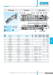
Einheitsbohrungen Basic holes Alésages identiques<br />
d2<br />
C2<br />
d2<br />
d2<br />
d2<br />
d2<br />
d2<br />
4<br />
d2<br />
C3<br />
d2<br />
d2<br />
d2<br />
d2<br />
d2<br />
d d d<br />
d<br />
C1<br />
d<br />
STRACK NORMA GmbH & Co. KG • Tel.: +49 (0) 23 51 / 87 01-0 • Fax: +49 (0) 23 51 / 87 01-100<br />
D 3001 03.2012<br />
1.4.3
Säulengestelle / Die <strong>sets</strong> / Blocks à <strong>colonnes</strong><br />
www.strack.de<br />
Einheitsbohrungen Basic holes Alésages identiques<br />
d2<br />
C2<br />
d2<br />
d2<br />
d2<br />
d2<br />
4<br />
d2<br />
C3<br />
d2<br />
d2<br />
d2<br />
d2<br />
d d d<br />
d<br />
C1<br />
d<br />
1.4.4<br />
STRACK NORMA GmbH & Co. KG • Tel.: +49 (0) 23 51 / 87 01-0 • Fax: +49 (0) 23 51 / 87 01-100 D 3001 03.2012
Säulengestelle / Die <strong>sets</strong> / Blocks à <strong>colonnes</strong><br />
www.strack.de<br />
Combi-Säulengestelle Combi-<strong>die</strong> <strong>sets</strong> Combi-<strong>blocs</strong> à <strong>colonnes</strong><br />
Größenübersicht Size overvie Enseble des dimensions<br />
c2<br />
c2<br />
c3<br />
c3<br />
c1<br />
a1<br />
b1<br />
c1<br />
a1 b1 C1 C2 C3<br />
27 37 47 57 67 27 37 47 57 67 27 37<br />
156 156 x x x x x<br />
196 x x x x x<br />
246 x x x x x<br />
311 x x x x x<br />
196 196 x x x x x<br />
246 x x x x x<br />
311 x x x x x<br />
396 x x x x x<br />
496 x x x x x x x<br />
626 x x x x x<br />
246 246 x x x x x<br />
311 x x x x x<br />
396 x x x x x<br />
496 x x x x x<br />
626 x x x x x<br />
706 x x x x x<br />
311 311 x x x x x<br />
396 x x x x x<br />
496 x x x x x<br />
626 x x x x x<br />
706 x x x x x<br />
796 x x x x x<br />
396 396 x x x x x<br />
496 x x x x x<br />
626 x x x x x<br />
706 x x x x x<br />
796 x x x x x<br />
496 496 x x x x x<br />
626 x x x x x<br />
706 x x x x x<br />
796 x x x x x<br />
626 626 x x x x x<br />
706 x x x x x<br />
796 x x x x x<br />
a1<br />
b1<br />
4<br />
STRACK NORMA GmbH & Co. KG • Tel.: +49 (0) 23 51 / 87 01-0 • Fax: +49 (0) 23 51 / 87 01-100<br />
D 3001 03.2012<br />
1.4.5
Säulengestelle / Die <strong>sets</strong> / Blocks à <strong>colonnes</strong><br />
www.strack.de<br />
Combi-Säulengestelle Combi-<strong>die</strong> <strong>sets</strong> Combi-<strong>blocs</strong> à <strong>colonnes</strong><br />
Auswahlhilfe Selection guide Guide desélection<br />
4<br />
Beispielstückliste / Example part list /<br />
Liste des pièces des exemples<br />
Artikelbezeichnung / Article /<br />
Désignation de l‘article<br />
Stck<br />
1.1 SG-65-C1-246-196-37-1.1730 1 Gestellplatte / Die set plate / Plaque de bloc à <strong>colonnes</strong><br />
1.2 SG-6-C2-246-196-37-1.1730 1 Gestellplatte / Die set plate / Plaque de bloc à <strong>colonnes</strong><br />
1.3 SN1769-24-40-B 1 Führungsbuchse/ Guide bushe / Bague de guidage<br />
1.4 SN1769-25-40-B 1 Führungsbuchse/ Guide bushe / Bague de guidage<br />
1.5 SN4321-24-200 1 Führungssäule / Guide pillar / Colonne de guidage<br />
1.6 SN4321-25-200 1 Führungssäule / Guide pillar / Colonne de guidage<br />
1.7 SN3500-M5-16 8 Zylinderschraube / Cylinder screws / Vis 6 pans creux<br />
1.8 SN1707-32-8 2 Haltescheibe / Retaining ring / Rodelle de fixation<br />
1.<br />
Kombinieren Sie in 4 Schritten aus einer großen Anzahl<br />
von STRACK Führungselementen und Gestellplatten Ihr<br />
individuelles Säulengestell.<br />
Im 1. Schritt bestimmen Sie, ob <strong>die</strong> Säulen in der Grundoder<br />
Kopfplatte montiert werden sollen. (Seiten 8 und 9)<br />
Im 2. Schritt definieren Sie <strong>die</strong> Art der Arbeitsfläche, <strong>die</strong><br />
Anzahl der Gestellplatten, den Typ der Führungselemente<br />
und deren Befestigungsart.<br />
Weiter auf der sich durch Ihre Auswahl ergebenen Seite.<br />
Im 3. Schritt legen Sie <strong>die</strong> Plattenabmaße und somit <strong>die</strong><br />
resultierenden Parameter, wie z.B. <strong>die</strong> Größe der Arbeitsfläche<br />
und <strong>die</strong> Führungsdurchmesser fest.<br />
Die Seitenangabe unter der Abbildung der Führungselemente<br />
leitet Sie zu den passenden Führungselementen.<br />
Im 4. Schritt definieren Sie <strong>die</strong> sich durch Ihre Auswahl<br />
ergebenen Führungselemente.<br />
2.<br />
Combi Säulengestelle<br />
mit unten stehenden Säulen<br />
Combi-<strong>die</strong> <strong>sets</strong><br />
with down-mounted columns<br />
Combi-<strong>blocs</strong> à <strong>colonnes</strong><br />
avec <strong>colonnes</strong> montées en bas<br />
Befestigungsart der Führungselemente Mounting type of the guide elements Type de montage des elements de guidage<br />
Combine your individual <strong>die</strong> set in four steps out of a great<br />
number of STRACK guide elements and <strong>die</strong> set plates.<br />
In the first step determine whether the columns should be<br />
mounted in the base plate or the top plate (pages 8 and 9).<br />
In the second step define the kind of the work surface, the<br />
number of the <strong>die</strong> set plates, the type of the guide elements<br />
and their mounting type.<br />
Continue with the page resulting from your selection.<br />
In the third step you determine the plate dimensions and<br />
thus the resulting parameters, like for example the size of<br />
the working surface and the guide diameter.<br />
The page reference under the illustration “guide elements”<br />
will lead you to the suitable guide elements.<br />
In the fourth step you define the guide elements resulting<br />
from your selection.<br />
Arbeitsflächen<br />
Working surfaces<br />
Plans de travail<br />
Anzahl der Platten<br />
Number of the plates<br />
Nombre des plaques<br />
Seite / Page<br />
4.10<br />
Seite / Page<br />
4.10<br />
Seite / Page<br />
4.16<br />
Seite / Page<br />
4.16<br />
Seite / Page<br />
4.22<br />
Seite / Page<br />
4.22<br />
Seite / Page<br />
4.28<br />
Seite / Page<br />
4.11<br />
Seite / Page<br />
4.11<br />
Seite / Page<br />
4.17<br />
Seite / Page<br />
4.17<br />
Seite / Page<br />
4.23<br />
Seite / Page<br />
4.23<br />
Seite / Page<br />
4.29<br />
Seite / Page<br />
4.12<br />
Seite / Page<br />
4.12<br />
Seite / Page<br />
4.18<br />
Seite / Page<br />
4.18<br />
Seite / Page<br />
4.24<br />
Seite / Page<br />
4.24<br />
Seite / Page<br />
4.30<br />
Seite / Page<br />
4.13<br />
Seite / Page<br />
4.13<br />
Seite / Page<br />
4.19<br />
Seite / Page<br />
4.19<br />
Seite / Page<br />
4.25<br />
Seite / Page<br />
4.25<br />
Seite / Page<br />
4.31<br />
Seite / Page<br />
4.14<br />
Seite / Page<br />
4.14<br />
Seite / Page<br />
4.20<br />
Seite / Page<br />
4.20<br />
Seite / Page<br />
4.26<br />
Seite / Page<br />
4.26<br />
Seite / Page<br />
4.32<br />
Seite / Page<br />
4.15<br />
Seite / Page<br />
4.15<br />
Seite / Page<br />
4.21<br />
Seite / Page<br />
4.21<br />
Seite / Page<br />
4.27<br />
Seite / Page<br />
4.27<br />
Seite / Page<br />
4.33<br />
Combinez votre bloc à colonne individuel en quatre pas du<br />
grand nombre des STRACK élements de guidages et des<br />
plaques de bloc à <strong>colonnes</strong>.<br />
Dans un premier pas déterminez si les <strong>colonnes</strong> doivent être<br />
montées dans la plaque de base ou la plaque de tête.<br />
Dans un deuxiéme pas définissez la mode du plan de<br />
travail, le nombre des plaques de bloc à <strong>colonnes</strong>, le type<br />
des éléments de guidage et leur type de montage.<br />
Continuez avec la page résultante de votre sélection.<br />
Dans un troisième pas vous déterminez les dimensions des<br />
plaques et par conséquent les paramètres résultants, par<br />
exemple la grandeur du plan de travail et le diamètre de<br />
guidage.<br />
L’indication de la page sous l’image “élements de guidage”<br />
vous amène aux élements de guidage appropriées.<br />
Dans un quatrième pas vous définez les éléments de<br />
guidage résultants de votre sélection.<br />
1.4.6<br />
STRACK NORMA GmbH & Co. KG • Tel.: +49 (0) 23 51 / 87 01-0 • Fax: +49 (0) 23 51 / 87 01-100 D 3001 03.2012
S<br />
L<br />
Säulengestelle / Die <strong>sets</strong> / Blocks à <strong>colonnes</strong><br />
www.strack.de<br />
Combi-Säulengestelle Combi-<strong>die</strong> <strong>sets</strong> Combi-<strong>blocs</strong> à <strong>colonnes</strong><br />
Auswahlhilfe Selection guide Guide desélection<br />
3.<br />
Combi Säulengestelle<br />
mit unten stehenden Säulen<br />
Combi <strong>die</strong> <strong>sets</strong><br />
with down-mounted columns<br />
Combi <strong>blocs</strong> à <strong>colonnes</strong><br />
avec <strong>colonnes</strong> montées en bas<br />
Auswahl Gestellplatten Selection <strong>die</strong> set plates Sélection des plaques de bloc à <strong>colonnes</strong><br />
a1<br />
e1<br />
siehe Seite<br />
see page 4.40<br />
voir page<br />
d<br />
a2<br />
d1<br />
b1<br />
D D D<br />
SG-6-C2-...<br />
SG-6-C3-...<br />
SG-65-C1-...<br />
4<br />
d/d1<br />
SG-65-C1-<br />
a1-b1-D-Mat<br />
Mat.: 1.1730/C45W<br />
C1 C2<br />
C3<br />
SG a1 b1<br />
a2 e1 Ød Ød1<br />
D<br />
D<br />
D<br />
SG-65-C1/ 156 156 37 37 27 58 100 19 20<br />
SG-6-C2/ 196 37 37 27 98 140 19 20<br />
SG-6-C3 246 37 37 27 148 190 19 20<br />
311 37 37 27 213 255 19 20<br />
196 196 37 37 27 84 132 24 25<br />
246 37 37 27 134 182 24 25<br />
311 37 37 27 199 247 24 25<br />
396 37 37 27 284 332 24 25<br />
496 47 47 27 368 424 30 32<br />
626 47 47 27 498 554 30 32<br />
246 246 47 47 27 118 174 30 32<br />
311 47 47 27 183 239 30 32<br />
396 47 47 27 268 324 30 32<br />
496 47 47 27 368 424 30 32<br />
Führungssäulen mit 626 Bund Guide pillars with 47 collar / 57 Colonnes 47 / 57de guidage und Haltescheiben<br />
avec 27 474 Führungsbuchsen 542 38 Guide 40bushes<br />
4.<br />
706 47 / 57 47 / 57 mit Flansch<br />
with flange<br />
27 554 622 38 40<br />
311 311 47 47 27 183 SN 1766- 239 30 SN 1769- 32<br />
d<br />
d<br />
396 47 47 27 268 324 30 32<br />
light line<br />
496 47 / 57 47 / 57 27 344 412 38 40<br />
626 47 / 57 47 / 57 27 474 542 38 40<br />
d<br />
d<br />
d<br />
SN 1778-<br />
706 47 / 57 47 / 57 27 554 622 38 40<br />
796 47 / 57 47 / 57 27 644 712 38 40<br />
Mat.: 1.1740<br />
396 396 47 / 57 47 / 57 37 244SN 1766- 312 38 40<br />
52 ±2HRC+CuSn12 SN 1769-<br />
496 47 / 57 47 / 57 37 344 412 38 40<br />
626 57 / 67 57 / 67 37 452 SN 1766-d-L4-T530 48 SN 1769-d-L4-T 50<br />
Mat.:1.1213/63±2HRC<br />
Mat.: 1.1213/63 ±2HRC<br />
SN 4321-<br />
DIN 9825-4/ISO<br />
706182-5<br />
SN 4322-<br />
DIN 9825-4/ISO<br />
57 /<br />
9182-5<br />
67 57 / 67 37 532 610 48 50<br />
796 57 / 67 57 / 67 37 622 d L4 700 d L4 48 d L450<br />
19/20 35<br />
24/25 40<br />
30/32 50<br />
SN 4321-d-L1 496 SN 4322-d-L1 496 57 / 67 57 / 67 37 322 400 48 50<br />
50<br />
60<br />
75<br />
626 57 / 67 57 / 67 37 452 530 48 50<br />
d L1 L2<br />
d706 L1 L2<br />
d L1 L257 / 67<br />
d L1<br />
57<br />
L2/ 67<br />
d L1<br />
37<br />
L2<br />
532 SN 1778- 610 48 50<br />
19/20 100 23 24/25 100 30 30/32 112 37 38/40 125 37 48/50 140 47<br />
d<br />
796 57 / 67 57 / 67 37 622 700 48 50<br />
112 23<br />
112 30<br />
125 37<br />
140 37<br />
160 47<br />
125 23 626 125 30 626 140 37 57 / 67 160 5737/ 67 180 37 47 452 530 48 50<br />
140 23 706 140 30<br />
160 37 57 / 67 180 5737/ 67 200 37 47 532 610 48 50<br />
160 23<br />
160 30<br />
180 37<br />
200 37<br />
224 47<br />
796 57 / 67 57 / 67 37 622 700 48 50<br />
180 23<br />
200 23<br />
L1<br />
L2<br />
180 30<br />
200 30<br />
224 30<br />
250 30<br />
200 37<br />
224 37<br />
250 37<br />
280 37<br />
315 37<br />
L1<br />
L2<br />
224 37<br />
250 37<br />
280 37<br />
315 37<br />
355 37<br />
L1<br />
L2<br />
250 47<br />
280 47<br />
315 47<br />
355 47<br />
400 47<br />
SN 1778-<br />
SN 1778-d-L4<br />
L4 -0,3<br />
L4 -0,3<br />
Mat.: 1.3505<br />
63±2HRC+CuZn40<br />
d L4<br />
19/20 38<br />
51<br />
Mat.: 1.0501<br />
Sint-B50+MoS2<br />
d L4<br />
24/25 40<br />
60<br />
d<br />
L4 -0,3<br />
L4<br />
38/40 60<br />
85<br />
d L4<br />
30/32 47<br />
70<br />
Bagues de guidage<br />
avec collerette<br />
d L4<br />
48/50 80<br />
100<br />
d L4<br />
38/40 56<br />
80<br />
a) siehe Seite Info 1.153<br />
see page Info 1.159<br />
voir page Info 1.165<br />
T = B ^ = Standard<br />
T a)<br />
A/B/C<br />
A/B/C<br />
d L4<br />
48/50 66<br />
90<br />
M<br />
d<br />
d3<br />
SN 3550<br />
Mat.: 1.0718<br />
SN 1707-<br />
SN 1707-d3-M<br />
d3 M d S<br />
25 M8 19/20 5,5<br />
32 M8 24/25 5,5<br />
40 M8 30/32 7,5<br />
50 M8 38/40 9,5<br />
SN 3500-<br />
SN 3500-d-L<br />
DIN EN ISO 4762-10.9<br />
SN 1766<br />
SN 1769<br />
SN 1778<br />
d L Ø L4 L4<br />
M4 12 19/20 35 38<br />
25 50 51<br />
M5 16 24/25 40 40<br />
25 60 60<br />
16 30/32 50 47<br />
30 75 70<br />
SN 1766<br />
SN 1769<br />
SN 1778<br />
d L Ø L4 L4<br />
M6 25 38/40 60 56<br />
40 85 80<br />
M8 35 48/50 80 66<br />
45 100 90<br />
STRACK NORMA GmbH & Co. KG • Tel.: +49 (0) 23 51 / 87 01-0 • Fax: +49 (0) 23 51 / 87 01-100<br />
D 3001 03.2012<br />
1.4.7
Säulengestelle / Die <strong>sets</strong> / Blocks à <strong>colonnes</strong><br />
www.strack.de<br />
Combi-Säulengestelle<br />
mit unten stehenden Säulen<br />
Combi-<strong>die</strong> <strong>sets</strong><br />
with down-mounted columns<br />
Combi-<strong>blocs</strong> à <strong>colonnes</strong><br />
avec <strong>colonnes</strong> montées en bas<br />
Befestigungsart der Führungselemente Mounting type of the guide elements Type de montage des elements de guidage<br />
4<br />
Arbeitsflächen<br />
Working surfaces<br />
Plans de travail<br />
Anzahl der Platten<br />
Number of the plates<br />
Nombre des plaques<br />
Seite / Page<br />
4.10<br />
Seite / Page<br />
4.11<br />
Seite / Page<br />
4.12<br />
Seite / Page<br />
4.13<br />
Seite / Page<br />
4.14<br />
Seite / Page<br />
4.15<br />
Seite / Page<br />
4.10<br />
Seite / Page<br />
4.11<br />
Seite / Page<br />
4.12<br />
Seite / Page<br />
4.13<br />
Seite / Page<br />
4.14<br />
Seite / Page<br />
4.15<br />
Seite / Page<br />
4.16<br />
Seite / Page<br />
4.17<br />
Seite / Page<br />
4.18<br />
Seite / Page<br />
4.19<br />
Seite / Page<br />
4.20<br />
Seite / Page<br />
4.21<br />
Seite / Page<br />
4.16<br />
Seite / Page<br />
4.17<br />
Seite / Page<br />
4.18<br />
Seite / Page<br />
4.19<br />
Seite / Page<br />
4.20<br />
Seite / Page<br />
4.21<br />
Seite / Page<br />
4.22<br />
Seite / Page<br />
4.23<br />
Seite / Page<br />
4.24<br />
Seite / Page<br />
4.25<br />
Seite / Page<br />
4.26<br />
Seite / Page<br />
4.27<br />
Seite / Page<br />
4.22<br />
Seite / Page<br />
4.23<br />
Seite / Page<br />
4.24<br />
Seite / Page<br />
4.25<br />
Seite / Page<br />
4.26<br />
Seite / Page<br />
4.27<br />
Seite / Page<br />
4.28<br />
Seite / Page<br />
4.29<br />
Seite / Page<br />
4.30<br />
Seite / Page<br />
4.31<br />
Seite / Page<br />
4.32<br />
Seite / Page<br />
4.33<br />
1.4.8<br />
STRACK NORMA GmbH & Co. KG • Tel.: +49 (0) 23 51 / 87 01-0 • Fax: +49 (0) 23 51 / 87 01-100 D 3001 03.2012
Säulengestelle / Die <strong>sets</strong> / Blocks à <strong>colonnes</strong><br />
www.strack.de<br />
Combi-Säulengestelle<br />
mit oben hängenden Säulen<br />
Combi-<strong>die</strong> <strong>sets</strong><br />
with aerial-mounted columns<br />
Combi-<strong>blocs</strong> à <strong>colonnes</strong><br />
avec <strong>colonnes</strong> montées en haut<br />
Befestigungsart der Führungselemente Mounting type of the guide elements Type de montage des elements de guidage<br />
Arbeitsflächen<br />
Working surfaces<br />
Plans de travail<br />
Anzahl der Platten<br />
Number of the plates<br />
Nombre des plaques<br />
4<br />
Seite / Page<br />
4.34<br />
Seite / Page<br />
4.35<br />
Seite / Page<br />
4.36<br />
Seite / Page<br />
4.37<br />
Seite / Page<br />
4.38<br />
Seite / Page<br />
4.39<br />
Seite / Page<br />
4.34<br />
Seite / Page<br />
4.35<br />
Seite / Page<br />
4.36<br />
Seite / Page<br />
4.37<br />
Seite / Page<br />
4.38<br />
Seite / Page<br />
4.39<br />
Seite / Page<br />
4.40<br />
Seite / Page<br />
4.41<br />
Seite / Page<br />
4.42<br />
Seite / Page<br />
4.43<br />
Seite / Page<br />
4.44<br />
Seite / Page<br />
4.45<br />
Seite / Page<br />
4.40<br />
Seite / Page<br />
4.41<br />
Seite / Page<br />
4.42<br />
Seite / Page<br />
4.43<br />
Seite / Page<br />
4.44<br />
Seite / Page<br />
4.45<br />
Seite / Page<br />
4.46<br />
Seite / Page<br />
4.47<br />
Seite / Page<br />
4.48<br />
Seite / Page<br />
4.49<br />
Seite / Page<br />
4.50<br />
Seite / Page<br />
4.51<br />
Seite / Page<br />
4.46<br />
Seite / Page<br />
4.47<br />
Seite / Page<br />
4.48<br />
Seite / Page<br />
4.49<br />
Seite / Page<br />
4.50<br />
Seite / Page<br />
4.51<br />
Seite / Page<br />
4.52<br />
Seite / Page<br />
4.53<br />
Seite / Page<br />
4.54<br />
Seite / Page<br />
4.55<br />
Seite / Page<br />
4.56<br />
Seite / Page<br />
4.57<br />
STRACK NORMA GmbH & Co. KG • Tel.: +49 (0) 23 51 / 87 01-0 • Fax: +49 (0) 23 51 / 87 01-100<br />
D 3001 03.2012<br />
1.4.9
Säulengestelle / Die <strong>sets</strong> / Blocks à <strong>colonnes</strong><br />
www.strack.de<br />
Anfrage / Inquiry/ Demande de devis<br />
Auftrag / Order / Bon de commande<br />
Firma / Company / Société<br />
Straße / Street / Rue<br />
Ort / Town / Ville<br />
Name / Nom<br />
1 / 2<br />
STRACK NORMA GmbH & Co. KG<br />
Königsberger Str. 11<br />
58511 Lüdenscheid<br />
Tel.: 0 23 51 / 87 01-0<br />
Fax: 0 23 51 / 87 01-100<br />
E-Mail: info@strack.de<br />
Fotokopieren, ausfüllen und per Fax an uns.<br />
Please copy, fill in and fax to us.<br />
Photocopier, remplir et nous retourner.<br />
Tel., Fax<br />
Auftrags-Nr. / Order No. / V/Réf.<br />
Dat.<br />
Mat.: 1.1730<br />
Mat.: 3.4365 (AL)<br />
4<br />
C2 =<br />
C1 =<br />
C2 =<br />
C3 =<br />
C1 =<br />
C2 =<br />
C1 =<br />
C2 =<br />
C3 =<br />
C1 =<br />
a1=<br />
e1=<br />
a2=<br />
a1=<br />
e1=<br />
a2=<br />
b1=<br />
e2=<br />
b1=<br />
b2=<br />
d= d1=<br />
d= d1=<br />
a1=<br />
e1=<br />
a2=<br />
a1=<br />
e1=<br />
a2=<br />
b2=<br />
e2=<br />
2<br />
b1=<br />
e3=<br />
b3=<br />
b1=<br />
d1=<br />
d1=<br />
1.4.70<br />
STRACK NORMA GmbH & Co. KG • Tel.: +49 (0) 23 51 / 87 01-0 • Fax: +49 (0) 23 51 / 87 01-100 D 3001 03.2012
Säulengestelle / Die <strong>sets</strong> / Blocks à <strong>colonnes</strong><br />
www.strack.de<br />
Anfrage / Inquiry/ Demande de devis<br />
Auftrag / Order / Bon de commande<br />
2 / 2<br />
Fotokopieren, ausfüllen und per Fax an uns.<br />
Firma / Company / Société<br />
Auftrags-Nr. / Order No. / V/Réf.<br />
Dat.<br />
Please copy, fill in and fax to us.<br />
Photocopier, remplir et nous retourner.<br />
SN 4190-<br />
d<br />
Z 4411-<br />
d<br />
Z 4412-<br />
d<br />
Z 4415-<br />
d<br />
SN 1766-<br />
d<br />
SN 1769-<br />
d<br />
SN 1778-<br />
d<br />
L1<br />
L1<br />
L1<br />
L1<br />
L4<br />
L4<br />
L4<br />
Mat.: Bronze 190–220 HB<br />
190 S10/3000<br />
Mat.:1.1740<br />
HRC 52 ±2+CuSn12<br />
Mat.-Nr. 1.0501<br />
Sint-B50+MoS2<br />
Mat.: 1.3505/<br />
63±2HRC+CuZn40<br />
Mat.: 1.1740<br />
52 ±2 HRC CuSn12<br />
Mat.-Nr. 1.0501<br />
Sint-B50+MoS2<br />
Mat.: 1.3505/<br />
63±2HRC+CuZn40<br />
4<br />
d L1 1 2 ..... 8 L1 1 2 ..... 8 L1 1 2 ..... 8 L1 1 2 ..... 8 L4 1 2 ..... 8 L4 1 2 ..... 8 L4 1 2 ..... 8<br />
19<br />
20<br />
24<br />
25<br />
30<br />
32<br />
38<br />
40<br />
48<br />
50<br />
Z 4310<br />
SN 4321<br />
SN 4322<br />
SN 1707<br />
SN 4325<br />
Type 1 Type 2<br />
dd<br />
L1<br />
d<br />
L1<br />
light<br />
line<br />
d<br />
L1<br />
d3<br />
SN 3550<br />
Mat.: 1213/63 ±2 HRC Mat.: 1213/63 ±2 HRC Mat.: 1213/63 ±2 HRC Mat.: 1.0718 Mat.: 1.0330<br />
d L1 1 2 ..... 8 L1 1 2 ..... 8 L1 1 2 ..... 8<br />
d3 1 2 ..... 8<br />
Type 1 2 ..... 8<br />
19<br />
25<br />
1<br />
20<br />
32<br />
∅ 16 - 32<br />
24<br />
40<br />
2<br />
25<br />
50<br />
∅ 38 - 80<br />
30<br />
32<br />
38<br />
40<br />
48<br />
50<br />
SN 4190 / Z 4411 / Z 4412 / Z 4415<br />
d<br />
S<br />
19/20 26<br />
24/25 29<br />
30/32 32<br />
38/40 36<br />
48/50 41<br />
S<br />
S<br />
SN 1766 / SN 1769/ SN 1778<br />
d S S1<br />
19/20 20 −<br />
24/25 24 30<br />
30/32 27 34<br />
38/40 33 40<br />
48/50 38 46<br />
S<br />
S1<br />
STRACK NORMA GmbH & Co. KG • Tel.: +49 (0) 23 51 / 87 01-0 • Fax: +49 (0) 23 51 / 87 01-100<br />
D 3001 03.2012<br />
1.4.71
Säulengestelle / Die <strong>sets</strong> / Blocks à <strong>colonnes</strong><br />
www.strack.de<br />
4<br />
mehr Informationen siehe<br />
Kapitel 1.7: Sondergestelle und Zusatzbearbeitungen<br />
more informations see<br />
Chapter 1.7: Special Die Sets and Additional Machining Facilities<br />
pour information, voir<br />
Chapitre 1.7: Blocs spéciaux et usinages complémentaires<br />
1.4.72<br />
STRACK NORMA GmbH & Co. KG • Tel.: +49 (0) 23 51 / 87 01-0 • Fax: +49 (0) 23 51 / 87 01-100 D 3001 03.2012
Sonderbearbeitung / Special finishing /<br />
Usinages complementaires<br />
NORMALIEN<br />
Die Kapazitäten von 45 Maschinen werden zur Verfügung gestellt<br />
The capacities of 45 machines are placed at the disposal<br />
La capacité de 45 machines est mise à la disposition<br />
Das Bearbeitungspektrum umfasst:<br />
•4 Bearbeitungszentren im 5-Achsen-Bereich<br />
1200 mm x 1600 mm x 1000 mm bis zu 3000 kg<br />
•10 Bearbeitungszentren im 3-Achsen-Bereich<br />
1400 mm x 3000 mm x 800 mm bis zu 3500 kg<br />
•9 Umfang-Schleifmaschinen<br />
1400 mm x 3000 mm x 800 mm bis zu 3000 kg<br />
•3 Segment-Schleifmaschinen<br />
800 mm x 1600 mm x 600 mm bis zu 3000 kg<br />
•2 Tiefbohrzentren<br />
1500 mm x 2000 mm x 450 mm bis zu 3000 kg<br />
•3 Messmaschinen<br />
1200 mm x 2200 mm x 600 mm bis zu 3000 kg<br />
•2 Koordinatenschleifmaschinen<br />
800 mm x 1200 mm x 200 mm bis zu 1000 kg<br />
•CAD mit Schnittstellen<br />
zu allen gängigen Systemen<br />
•Programmierung im 2 + 3 D-Bereich<br />
•Diverse Sondermaschinen<br />
•Zusammen mit unseren Partnern<br />
können wir Ihnen zusätzlich anbieten<br />
Ero<strong>die</strong>r- und Drehbearbeitung<br />
bis hin zur<br />
Komplettlösung mit Warmbehandlung<br />
Maschinenstand 12.2006<br />
Info 8<br />
The machining spectrum comprises:<br />
•4 machining centres in the 5-axis-range<br />
1200 mm x 1600 mm x 1000 mm up to 3000 kg<br />
•10 machining centres in the 3-axis-range<br />
1400 mm x 3000 mm x 800 mm up to 3500 kg<br />
•9 circumferential grinding machines<br />
1400 mm x 3000 mm x 800 mm up to 3000 kg<br />
•3 segment-grinding machines<br />
800 mm x 1600 mm x 600 mm up to 3000 kg<br />
•2 deep drilling centres<br />
1500 mm x 2000 mm x 450 mm up to 3000 kg<br />
•3 measuring machines<br />
1200 mm x 2200 mm x 600 mm up to 3000 kg<br />
•2 coordinate grinding machines<br />
800 mm x 1200 mm x 200 mm up to 1000 kg<br />
•CAD with interfaces<br />
to all popular systems<br />
•programming in 2 + 3 D range<br />
•diverse special machines<br />
•Together with our partners<br />
we can additionally offer to you<br />
Erosion- and turning machining<br />
up to<br />
perfect solution with heat treatment<br />
machine situation 12.2006<br />
Le spectre de l’usinage comprend:<br />
•4 machines universelles d’usinage dans le domaine<br />
de 5 axes<br />
1200 mm x 1600 mm x 1000 mm jusqu’à 3000 kg<br />
•10 machines universelles d’usinge dans le domai<br />
ne de 3 axes<br />
1400 mm x 3000 mm x 800 mm jusqu’à 3500 kg<br />
•9 meuleuses de périphérique<br />
1400 mm x 3000 mm x 800 mm jusqu’à 3000 kg<br />
•3 meuleuses de segment<br />
800 mm x 1600 mm x 600 mm jusqu’à 3000 kg<br />
•2 centres de perçage profond<br />
1500 mm x 2000 mm x 450 mm jusqu’à 3000 kg<br />
•3 machines à mesurer<br />
1200 mm x 2200 mm x 600 mm jusqu’à 3000 kg<br />
•2 meuleuses de coordonnées<br />
800 mm x 1200 mm x 200 mm up to 1000 kg<br />
•CAD avec interfaces<br />
pour tous les systèmes courants<br />
•Programmation dans le domaine 2 + 3 D<br />
•machines spéciales diverses<br />
•Ensemble avec nos partenaires<br />
nous vous pouvons offrir additionnement<br />
traitement par ériosion et tournage<br />
jusqu’à<br />
la soloution complète avec traitement termique<br />
Situation des machines 12.2006
INFORMATIONEN KAPITEL 4<br />
INFORMATION CHAPTER 4<br />
INFORMATIONS CHAPITRE 4
Säulengestelle / Die <strong>sets</strong> / Blocks a <strong>colonnes</strong><br />
www.strack.de<br />
Information deutsch<br />
4<br />
Alle Gleitführungsbuchsen sind mit einem<br />
Toleranzkennzeichen A/B/C versehen, so dass<br />
eine optimale Auswahl des erforderlichen Gesamtlaufspiels<br />
konstruktiv vorbestimmt werden kann.<br />
Auswahlkriterien des Führungsspiels:<br />
– nach dem Schneidspalt<br />
– nach der Werkstoffdicke<br />
– nach Art und Erhaltungszustand der Arbeitsmaschine.<br />
(Siehe Tabelle Paarungsklassifizierung Seite 4.73.)<br />
Z 4310<br />
Führungssäulen ~ DIN 9825 zum Einpressen<br />
Werkstoff 1.1213<br />
Oberflächenhärte 63 ± 2 HRC<br />
induktiv gehärtet<br />
Die Lauffläche der Säule ist feingeschliffen und<br />
gefinisht.<br />
Der 7 mm lange Zentrieransatz ermöglicht ein problemloses<br />
Einsetzen der Säule in <strong>die</strong> Aufnahmebohrung<br />
und garantiert, dass beim Einpressen ein Verkanten<br />
vermieden wird.<br />
Ab dem Durchmesser 19 mm sind alle Säulen mit<br />
einem Innengewinde M 8 x 20 zur Befestigung eines<br />
Käfighalters Z 4327 versehen.<br />
Einbau in <strong>die</strong> Aufnahmebohrung siehe Seite 4.78<br />
(Toleranzblatt).<br />
Bei der Montage wird durch das Auftragen von<br />
Z 9060 eine Kaltverschweißung vermieden.<br />
Anwendungsgebiet:<br />
Bei allen Arten von Säulengestellen sowie im<br />
Maschinen-, Vorrichtungs- und Apparatebau.<br />
Z 4321<br />
Führungssäulen DIN 9825-4 mit Bund<br />
Werkstoff 1.1213<br />
Oberflächenhärte 63 ± 2 HRC<br />
induktiv gehärtet<br />
Sie sind leicht und schnell zu demontieren und erleichtern<br />
dadurch das Nachschleifen der Werkzeuge.<br />
Zur Befestigung sind wahlweise Haltescheiben<br />
SN 1707 oder Halteklammern Z 4325 einzusetzen.<br />
Einbau in Aufnahmebohrung siehe Seite 4.78<br />
(Toleranzblatt).<br />
Ab dem Durchmesser 19 mm sind alle Säulen mit<br />
einem Innengewinde M 8 x 20 zur Befestigung eines<br />
Käfighalters Z 4327 versehen.<br />
Bei der Montage wird durch das Auftragen von Z 9060<br />
eine Kaltverschweißung vermieden.<br />
Anwendungsgebiet:<br />
Bei allen Arten von Stanzwerkzeugen, bei denen eine<br />
schnelle Montage oder Demontage der Säulen erforderlich<br />
ist.<br />
Z 4322 light line<br />
Führungssäulen DIN 9825-4 mit Bund wie Ausführung<br />
SN 4321 jedoch kopfseitig kein Gewinde. Laufflächen<br />
Durchmessertoleranz h4 ohne finishing (Rz = 4).<br />
Nur für Einsatz mit Gleitführungsbuchsen geeignet!<br />
Z 4411 / SN 1766<br />
Bronzebeschichtete Führungsbuchsen<br />
Z 4411 ~ DIN 9831/ISO 9448.<br />
Die harte Sonderbronze (Zugfestigkeit 855 N/mm 2 )<br />
besitzt eine sehr gute Wärmeleitfähigkeit, sodass<br />
entstehende Reibungswärme sehr schnell abgeführt<br />
werden kann. Ein Kaltverschweißen, auch bei starker<br />
Reibung zwischen Säule und Buchse, wird somit weitgehend<br />
vermieden. Die Bronzeschicht (Schichtdicke<br />
ca. 0,1 mm), wird galvanisch auf einen gehärteten<br />
Stahlkörper aufgetragen, der verhindert, dass sich <strong>die</strong><br />
Buchse bei starker Kantenpressung deformiert. Sie ist<br />
somit für hohe Gleitgeschwindigkeit (15–30 m/min.),<br />
lange Lebensdauer, größte Führungsgenauigkeit bei<br />
sichergestellter Ölversorgung geeignet.<br />
Alle bronzebeschichteten Buchsen sind mit einem<br />
Schmiernippel, Anschlussgewinde M 8 x 1/kurze<br />
Ausführung M 6, versehen.<br />
Bei schnelllaufenden Stanzautomaten wird nach<br />
Entfernen des Schmiernippels der Anschluss an <strong>die</strong><br />
Zentralschmierung der Maschinen empfohlen.<br />
Einbau in <strong>die</strong> Aufnahmebohrung Passung H5.<br />
Vor der Montage wird das Auftragen von Festschmierstoff<br />
Z 9060 auf den Einbaudurchmesser<br />
empfohlen. Alle Buchsen der Serie Z 44 . . und<br />
SN 4190 sind pro Führungsdurchmesserpaar mit<br />
einem einheitlichen Außendurchmesser versehen<br />
und somit untereinander austauschbar.<br />
Z 4412 / SN 1769<br />
Feststoffgeschmierte, wartungsfreie Führungsbuchsen<br />
aus Sinterbronze<br />
Z 4412 ~ DIN 9831/ISO 9448.<br />
In <strong>die</strong>ser Sinterbronze ist in gleicher und feiner<br />
Verteilung Molybdändisulfid als Festschmierstoff eingelagert.<br />
Die guten Gleiteigenschaften einer gesinterten<br />
Bronze mit der hervorragenden Schmierwirkung<br />
von MoS 2<br />
sind somit vereint.<br />
Die Sinterbronze ist von einem Stahlmantel umgeben,<br />
der maßlich DIN 9831/ISO 9448 (Z 4412) entspricht.<br />
Diese Buchse eignet sich überall dort, wo<br />
– flüssige Schmierstoffe nicht vertretbare<br />
Rückstände hinterlassen würden (Lebensmittelverarbeitung/Verpackung,<br />
Textil- und Papiermaschinenbau).<br />
Einbau in <strong>die</strong> Aufnahmebohrung Passung H5.<br />
Vor der Montage wird das Auftragen von Festschmierstoff<br />
Z 9060 auf den Einbaudurchmesser<br />
empfohlen.<br />
Das Herausfahren der Führungssäule aus der Buchse<br />
bei jedem Arbeitshub ist zu vermeiden.<br />
Max. Gleitgeschwindigkeit zwischen 30 – 60 m/min.<br />
SN 4190<br />
Feststoffgeschmierte, wartungsarme<br />
Gleitführungsbuchsen aus Bronze<br />
Sie eignen sich besonders für den Einsatz bei<br />
hohen Belastungen, bei Gleitgeschwindigkeiten<br />
< 0,5 m/s, sowie schwer zugänglichen Lagerstellen.<br />
Die Anordnung der Festschmierstoff-Einsätze erfolgte<br />
so, dass in Gleitrichtung eine Überdeckung gegeben<br />
ist. Die Festschmierstoff-Einsätze gewährleisten einen<br />
gleichmäßigen Schmierfilm zwischen Säule und Buchse,<br />
der einen metallischen Kontakt verhindert und einem<br />
Anfressen entgegenwirkt. Die Gleitführungsbuchsen sind<br />
für lineare und drehende Gleitrichtungen ausgelegt.<br />
Temperatur-Einsatzbereich - 50 + 150° C<br />
(Eigenerwärmung beachten)<br />
Härteunterschied zwischen<br />
Buchse und Säule > 150 HB.<br />
Zu beachten ist das größere Laufspiel, besonders bei<br />
drehender Bewegung.<br />
Diese Buchsen sind mit folgenden Säulen<br />
kombinierbar: SN 1705, SN 4321, Z 4310, Z 4315,<br />
Z 4318, Z 4320, Z 4330.<br />
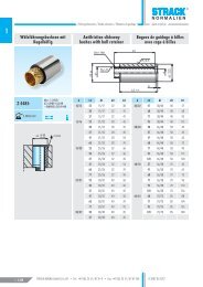
Z 4415 / SN 1778<br />
Wälzführungsbuchsen<br />
Z 4415 ~ DIN 9831/ISO 9448 mit Kugelkäfigen aus<br />
Messing SN 1799 werden höchsten Anforderungen an<br />
Leichtgängigkeit, Lebensdauer und Wartungsfreiheit<br />
gerecht und werden vorwiegend bei schnellaufenden<br />
kurzhubigen Pressen ab 400 Hüben/min. eingesetzt.<br />
Die Lastaufnahme senkrecht zur Bewegungsrichtung ist<br />
abhängig vom Kugeldurchmesser, von der Anzahl der<br />
im Eingriff befindlichen (tragenden) Kugeln und von<br />
der Vorspannung (negatives Führungsspiel). Da <strong>die</strong><br />
Erhöhung der Vorspannung zu Lasten der Lebensdauer<br />
und der Leichtgängigkeit geht, können auftretende<br />
Seitenkräfte nur über <strong>die</strong> Führungslänge aufgenommen<br />
und beeinflusst werden. Somit sollte in der unteren<br />
Hublage, wo <strong>die</strong> max. Belastung zu erwarten ist, der<br />
Kugelkäfig über seine gesamte Länge im Eingriff (tragend)<br />
sein. Vor der Montage wird das Auftragen von<br />
Festschmierstoff Z 9060 auf den Einbaudurchmesser<br />
empfohlen.<br />
Z 4425<br />
Wie Z 4415, jedoch zusätzlich mit 2 Anlaufringen als<br />
Hubbegrenzung für den Kugelkäfig SN 1798.<br />
Bevorzugter Einsatz im 2-Platten-Werkzeug.<br />
SN 1798<br />
Kugelkäfig aus Messing.<br />
Die einzelnen Kugeln sind ringförmig versetzt angeordnet,<br />
so dass jede Kugel auf einer eigenen Bahn läuft.<br />
Die Kugeln sind aus hochverschleißfestem, gehärtetem<br />
Spezialstahl hergestellt und entsprechen der Güteklasse<br />
1, Sortierung 0, DIN 5401.<br />
Alle Kugelkäfige SN 1798 und SN 1799 sind mit<br />
erhöhter Kugelzahl ausgestattet und somit unempfindlicher<br />
gegen Seitenkräfte.<br />
SN 1799<br />
Wie SN 1798, jedoch mit zusätzlichem Seegering versehen,<br />
der ein „Wandern“ des Käfigs verhindert.<br />
1.4.74<br />
STRACK NORMA GmbH & Co. KG • Tel.: +49 (0) 23 51 / 87 01-0 • Fax: +49 (0) 23 51 / 87 01-100 D 3001 03.2012
Säulengestelle / Die <strong>sets</strong> / Blocks a <strong>colonnes</strong><br />
www.strack.de<br />
Information deutsch<br />
Paarungsklassifizierung − Führungssäulen mit Gleitführungen<br />
Schneidspalte:<br />
Die Feststellung der Schneidspalte durch den Konstrukteut hängt in hohem<br />
Maße von der Ausführung des Blechwerkstückes ab: Anteil Glattzone/<br />
Bruchzone, sowie erlaubte Grathöhe. Weitere Einflussfaktoren sind:<br />
Stoff-Eigenschaften des Werkstückes sowie Art und Zustand der verwendeten<br />
Arbeitsmaschine.<br />
Auswahlkriterien des Führungsspiels:<br />
Nach dem Schneidspalt; nach der Werkstoffdicke; nach Art und<br />
Erhaltungszustand der Arbeitsmaschine.<br />
Schneidspalte<br />
Führungsspiel Führungssäule Führungsbuchse<br />
klein<br />
mittel<br />
groß<br />
Werkstücke mit engen Toleranzen und bestimmten<br />
Eigenschaften der geschnittenen Konturen, außerdem<br />
dünne Werkstoffe.<br />
Werkstücke aus Blechen dicker als 1 mm,<br />
vorzugsweise bei Folge-Verbund-Werkzeugen.<br />
Bei geringen Anforderungen an <strong>die</strong> Kantenausbildung;<br />
Schneidedruck und Schneidarbeit sind bei großen<br />
Schneidspalten eindeutig geringer als bei kleinen oder<br />
mittleren Schneidspalten.<br />
Klasse 1<br />
Klasse 2<br />
Klasse 3<br />
Klasse1 A A<br />
Klasse 2 A B<br />
Klasse 3 A C<br />
Klasse 2 = Standard<br />
4<br />
Gesamt-<br />
Führungssäule µm führungsspiel<br />
µm<br />
Führungsbuchse µm<br />
A 4 - 9 A<br />
∅ 15/16 7 - 14 B ∅ 15/16<br />
12 - 19 C<br />
A 4 - 11 A<br />
∅ 19/20 9 - 16 B ∅ 19/20<br />
14 - 22 C<br />
A 5 - 12 A<br />
∅ 24/25 10 - 18 B ∅ 24/25<br />
16 - 25 C<br />
A 5 - 12 A<br />
∅ 30/32 10 - 19 B ∅ 30/32<br />
17 - 28 C<br />
A 5 - 13 A<br />
∅ 38/40 11- 21 B ∅ 38/40<br />
19 - 32 C<br />
A 6 - 14 A<br />
∅ 48/50 12 - 23 B ∅ 48/50<br />
21 - 35 C<br />
A 6 - 14 A<br />
∅ 60/63 12 - 24 B ∅ 60/63<br />
22 - 36 C<br />
A 7 - 13 A<br />
∅ 80 13 - 23 B ∅ 80<br />
23 - 36 C<br />
-3 -2 -1 ±0 4 6 8 10 12 14 16 18 20 22 24 26 28 30 32 34<br />
Bei Bestellungen ohne nähere Angaben wird wie folgt geliefert:<br />
Führungssäule<br />
Führungsbuchse<br />
Führungssäulen SN 1705 - Z 4330 A<br />
Führungsbuchsen / Führungslager SN 1769 - Z 4411 A B<br />
Stahlgestelle, Zweisäulenausführung A B<br />
Stahlgestelle, Viersäulenausführung A B - C<br />
STRACK NORMA GmbH & Co. KG • Tel.: +49 (0) 23 51 / 87 01-0 • Fax: +49 (0) 23 51 / 87 01-100<br />
D 3001 03.2012<br />
1.4.75
Säulengestelle / Die <strong>sets</strong> / Blocks a <strong>colonnes</strong><br />
www.strack.de<br />
Information english<br />
4<br />
All guide bushes are marked A/B/C for tolerance so<br />
that the required total play can be optimally selected<br />
from the outset.<br />
Criteria for selecting the play:<br />
– <strong>die</strong> clearance<br />
– material thickness<br />
– type and condition of the machine used<br />
(see table “Classification of pairs“ on page 4.75).<br />
Z 4310<br />
Guide pillars ~ DIN 9825 for pressing in<br />
Material 1.1213<br />
Surface hardness 63 ± 2 HRC<br />
Induction-hardened<br />
The running surface of the pillar is precision<br />
ground and super finished.<br />
The 7 mm long centering shoulder ensures that the<br />
pillar can be fitted in the locating holes without<br />
difficulty and guarantees that it is not tilted when<br />
pressed in.<br />
From a diameter of 19 mm upwards, all pillars are<br />
provided with an M8 x 20 female thread for securing<br />
the Z 4327 holder for a ball retainer.<br />
Installation in locating hole, page 4.78<br />
(tolerance sheet).<br />
For assembly we recommend application of Z 9060<br />
solid lubricant in order to prevent cold setting.<br />
Applications:<br />
For all types of <strong>die</strong> <strong>sets</strong>, as well as in machine<br />
construction, construction of jigs and fixtures and<br />
apparatus engineering.<br />
Z 4321<br />
Guide pillars DIN 9825-4 with collar<br />
Material 1.1213<br />
Surface hardness 63 ± 2 HRC<br />
Induction-hardened<br />
These pillars can be demounted quickly and<br />
easily, thus making it easier to regrind the tools.<br />
For fixing SN 1707 retaining plates or Z 4325<br />
fixing devices can be used either.<br />
Installation in locating hole, page 4.78<br />
(tolerance sheet).<br />
From a diameter of 19 mm upwards, all pillars are<br />
provided with an M8 x 20 female thread for securing<br />
the Z 4327 holder for a ball retainer. For assembly we<br />
recommend application of Z 9060 solid lubricant in<br />
order to prevent cold welding.<br />
Applications:<br />
For all types of press tools requiring rapid<br />
assembly or disassembly of the pillars.<br />
Z 4322 light line<br />
Guide pillars DIN 9825-4 with collar like model<br />
SN 4321 however without a top end thread. Diameter<br />
tolerance of the sliding surface h4 without finishing<br />
(Rz =4). Are only suited for utilisation with guide<br />
bushes.<br />
Z 4411 / SN 1766<br />
Guide bushes, bronze plated<br />
Z 4411 ~ DIN 9831 / ISO 9448.<br />
This special bronze has an excellent thermal<br />
conductivity ensuring that friction of heat can be<br />
dissipated rapidly. This largely excludes the risk of<br />
cold welding, even in the presence of severe friction<br />
between pillars and bushes. The bronze coat (thickness<br />
approx. 0.1 mm) is galvanically deposited on the<br />
hardened steel body which in turn prevents the bushing<br />
from being deformed under high edge pressure. It<br />
therefore ensures high sliding speeds, a long service<br />
life, extremely accurate guidance if the oil supply is<br />
guaranteed. All bronzeplated guide bushes are provided<br />
with a lubricating nipple, connecting thread M8 x 1 /<br />
short version M6.<br />
The guide bushes should be connected to the central<br />
machine lubrication system after removing the lubricating<br />
nipple for use in high-speed automatic punching<br />
machines.<br />
Installation in locating hole size H5.<br />
Solid lubricant Z 9060 should be applied to the<br />
installation diameter prior to assembly. All bushes of<br />
series Z 44 . . and SN 4190 have a uniform outside<br />
diameter for each pair of guide diameters and are<br />
therefore interchangeable.<br />
Z 4412 / SN 1769<br />
Guide bushes, surface of sintered bronze with solid<br />
lubricant maintanance-free<br />
Z 4412 ~ DIN 9831/ ISO 9448<br />
Molybdenum disulphide is uniformly and finely<br />
dispersed in this sintered bronze as solid lubricant.<br />
In this way, the material <strong>combi</strong>nes the excellent sliding<br />
properties of a sintered bronze and the good lubricating<br />
properties of MoS 2<br />
.<br />
A firmly adhering, highly cohesive lubricant<br />
film is formed between the guide pillar and<br />
the bushes as a result of the sliding motion,<br />
thus preventing the guide elements from<br />
seizing up even at rest and when the machine<br />
tool starts up.<br />
The sintered bronze is encased in a steel sheath<br />
dimensioned in accordance with ~ DIN 9831 /<br />
ISO 9448 (Z 4412). This bush is ideal wherever<br />
– liquid lubricants would leave unacceptable<br />
residues (e. g. food processing or packaging, textiles<br />
and papermaking machines).<br />
Installation in the locating hole, size H5.<br />
Solid lubricant Z 9060 should be applied to the<br />
installation diameter prior to assembly.<br />
Maximum sliding speed 30 – 60 m/min.<br />
SN 4190<br />
Low-maintenance guide bushes of bronze, with solid<br />
lubricant.<br />
They are especially suitable for use under high loads,<br />
at sliding speeds < 0.5 m/s and at bearing points<br />
where access is difficult. The solid-lubricant inserts are<br />
arranged in such a way that there is an overlap in the<br />
sliding direction.<br />
The solid-lubricant inserts guarantee a uniform<br />
lubricating film between pillar and bush.<br />
The lubricating film prevents metallic contact and<br />
counter acts corrosion. The guide bushes are designed<br />
for linear and rotary sliding directions.<br />
Temperature range - 50 / + 150° C (take self-heating<br />
into account).<br />
Hardness difference between<br />
bush and pillar > 150 HB.<br />
The greater running clearance is to be taken into<br />
account, especially in the case of rotary motion.<br />
These bushes can be <strong>combi</strong>ned with the<br />
following pillars: SN 1705, SN 4321, Z 4310, Z 4315,<br />
Z 4318, Z 4320, Z 4330.<br />
Z 4415 / SN 1778<br />
Antifriction slideway bushes<br />
Z 4415 ~ DIN 9831 / ISO 9448 with ball retainers<br />
SN 1799 made of brass. These bushes meet the most<br />
stringent demands as regards smooth running, service<br />
life and minimum maintenance. They are primarily used<br />
in high-speed short-stroke presses operating at more<br />
than 400 strokes per minute.<br />
Load absorption perpendicular to the direction of<br />
movement depends on the ball diameter, the number<br />
of balls engaged and the preload. Since the service life<br />
and smooth running decrease as the preload increases,<br />
lateral forces can only be absorbed and influenced via<br />
the guide length. This means that the ball retainer<br />
should engage over its full length in the bottom limit<br />
position, since this is where the highest loads are to be<br />
expected. Solid lubricant Z 9060 should be applied to<br />
the installation diameter prior to assembly.<br />
Z 4425<br />
As Z 4415 but with two additional stop rings to limit<br />
the stroke length for ball retainer SN 1798.<br />
Preferably used in <strong>die</strong> <strong>sets</strong> without stripper plate.<br />
SN 1798<br />
Ball retainer (brass)<br />
The individual balls are offset in a ring, thus ensuring<br />
that each ball runs in its own race. The balls are made<br />
of high-strength, hardened special steel of quality<br />
class 1, grade 0 DIN 5401.<br />
All ball retainers SN 1798 and SN 1799 are fitted with<br />
a larger number of balls making them less sensitive to<br />
lateral forces.<br />
SN 1799<br />
As SN 1798 but with an additional Seeger circlip ring<br />
to prevent the retainer from “migrating“.<br />
1.4.76<br />
STRACK NORMA GmbH & Co. KG • Tel.: +49 (0) 23 51 / 87 01-0 • Fax: +49 (0) 23 51 / 87 01-100 D 3001 03.2012
Säulengestelle / Die <strong>sets</strong> / Blocks a <strong>colonnes</strong><br />
www.strack.de<br />
Information english<br />
Classification of pairs – Guide pillars with slideways<br />
Die clearance:<br />
The <strong>die</strong> clearance largely depends on the requirements imposed by the metal<br />
workpiece e.g. proportion of smooth zone to fracture zone and permissible<br />
burr height. The material properties of the workpiece and the type and<br />
condition of the machine used have also influence.<br />
Criteria for selecting the play:<br />
Die clearance; material thickness; type and condition of the machine used.<br />
Die clearance<br />
Play Guide pillar Guide bushes<br />
small<br />
medium<br />
large<br />
Workpieces with close tolerances and certain properties<br />
of the cut contours; also thin materials.<br />
Workpieces made of sheet metal thickness more<br />
than 1 mm, preferably for follow-on composite tools.<br />
Less stringent requirements with regard to edge definition;<br />
cutting pressure and cutting work are distinctly<br />
lower when working with a large <strong>die</strong> clearance than<br />
when working with a small or medium <strong>die</strong> clearance.<br />
Class 1<br />
Class 2<br />
Class 3<br />
Class 1 A A<br />
Class 2 A B<br />
Class 3 A C<br />
Class 2 = Standard<br />
4<br />
Total<br />
Guide pillar µm play<br />
µm<br />
Guide bushes µm<br />
A 4 - 9 A<br />
∅ 15/16 7 - 14 B ∅ 15/16<br />
12 - 19 C<br />
A 4 - 11 A<br />
∅ 19/20 9 - 16 B ∅ 19/20<br />
14 - 22 C<br />
A 5 - 12 A<br />
∅ 24/25 10 - 18 B ∅ 24/25<br />
16 - 25 C<br />
A 5 - 12 A<br />
∅ 30/32 10 - 19 B ∅ 30/32<br />
17 - 28 C<br />
A 5 - 13 A<br />
∅ 38/40 11- 21 B ∅ 38/40<br />
19 - 32 C<br />
A 6 - 14 A<br />
∅ 48/50 12 - 23 B ∅ 48/50<br />
21 - 35 C<br />
A 6 - 14 A<br />
∅ 60/63 12 - 24 B ∅ 60/63<br />
22 - 36 C<br />
A 7 - 13 A<br />
∅ 80 13 - 23 B ∅ 80<br />
23 - 36 C<br />
-3 -2 -1 ±0 4 6 8 10 12 14 16 18 20 22 24 26 28 30 32 34<br />
The following <strong>combi</strong>nations are supplied for unspecified orders:<br />
Guide pillar<br />
Guide bushes<br />
Guide pillars SN 1705 - Z 4330 A<br />
Guide bushes / Guide bearings SN 1769 - Z 4411 A B<br />
Steel <strong>die</strong> <strong>sets</strong>, two-pillar version A B<br />
Steel <strong>die</strong> <strong>sets</strong>, four-pillar version A B - C<br />
STRACK NORMA GmbH & Co. KG • Tel.: +49 (0) 23 51 / 87 01-0 • Fax: +49 (0) 23 51 / 87 01-100<br />
D 3001 03.2012<br />
1.4.77
Säulengestelle / Die <strong>sets</strong> / Blocks a <strong>colonnes</strong><br />
www.strack.de<br />
Information français<br />
4<br />
Toutes les bagues de guidage sont pourvous d‘un signe<br />
de tolérance « A/B/C » permettant le choix optimal du<br />
jeu de coupe total nécessaire<br />
Critères pour la sélection du jeu de guidage:<br />
– jeu de coupe<br />
– épaisseur de matière<br />
– type et condition de la machine utilsée<br />
(voir classification des appariements, page 4.77).<br />
Z 4310<br />
Colonnes de guidage ~ DIN 9825 montage à la presse<br />
Matériau 1.1213<br />
Dureté de surface 63 ± 2 HRC<br />
trempé par induction<br />
La surface de guidage des <strong>colonnes</strong> est finement<br />
rectifiée et finie.<br />
Le dégagement de diamètre, sur une hauteur de 7 mm<br />
permet l‘installation facile des <strong>colonnes</strong> dans leurs<br />
alésages et empêche tout mauvais alignement pendant<br />
le montage a la presse.<br />
A partir de 19 mm de diamètre, toutes les <strong>colonnes</strong><br />
sont pourvues d‘un filetage intérieur M8 x 20 pour la<br />
fixation d‘une rondelle de retenue de cage Z 4327.<br />
Montage dans l‘alésage ajustement voir page 4.78<br />
(feuille de tolérance).<br />
Pour le montage, nous recommandons d‘utiliser le<br />
lubrifiant solide Z 9060 afin d‘éviter tout soudage à<br />
froid.<br />
Domaines d‘utilisation:<br />
Pour tous les <strong>blocs</strong> à <strong>colonnes</strong> et dans la construction<br />
mécanique, la construction de gabarits et d‘appareils.<br />
Z 4321<br />
Colonnes de guidage DIN 9825-4 avec épaulement<br />
Matériau 1.1213<br />
Dureté de surface 63 ± 2 HRC<br />
trempé par induction<br />
Elles sont faciles et rapides à démonter, ce qui facilite<br />
le réaffutage des outils.<br />
Pour la fixation, on utilisera au choix les rondelles<br />
SN 1707 ou les brides Z 4325.<br />
Montage dans l‘alésage ajustement voir page 4.78<br />
(feuille de tolérance).<br />
A partir de 19 mm de diamètre, toutes les <strong>colonnes</strong><br />
sont pourvues d‘un filetage intérieur M8 x 20 pour la<br />
fixation d‘une rondelle de retenue de cage Z 4327.<br />
Pour le montage nous recommandons l‘utilisation d’un<br />
lubrifiant solide Z 9060 pour éviter un soudage à froid.<br />
Domaine d’application:<br />
Pour tous les outils de découpage nécessitant un<br />
montage ou démontage rapide des <strong>colonnes</strong>.<br />
Z 4322 light line<br />
Colonnes de guidage DIN 9825-4 avec collerette<br />
comme modèle SN 4321, cependant sans filet de tête.<br />
Tolérance de diamètre de la surface de roulement h4<br />
sans finissage (Rz = 4). Seulement appropriées pour<br />
l’utilisation avec des bagues pour guidage lisse.<br />
Z 4411 / SN 1766<br />
Bagues de guidage à revêtement de bronze<br />
Z 4411 ~ DIN 9831/ISO 9448.<br />
Ce bronze spécial possède un bonne conductivité<br />
thermique permettant d‘éliminer rapidement la chaleur<br />
résultant de la friction. Même en cas de forte friction<br />
entre la colonne et la bague, tout soudage à froid<br />
est ainsi évité. La couche de bronze (d‘une épaisseur<br />
d‘environ 0,1 mm) est appliquée par glavanisation<br />
sur un corps en acier trempé, ce qui empêche aussi<br />
toute déformation de la bague de guidage même en<br />
cas de forte pression sur les génératrices. Lorsque le<br />
graissage est effectué de manière adéquate, cette<br />
couche de bronze garantit donc un glissement optimal,<br />
une grande longévité, un guidage de grande précision.<br />
Toutes les bagues de guidage à revêtement de bronze<br />
sont pourvues d‘un raccord fileté de graissage, pas de<br />
raccordement M 8 x 1/version courte, M6.<br />
S‘agissant d‘outils de découpe travaillant très vite,<br />
après avoir enlevé le raccord fileté de graissage, il est<br />
recommandé de les raccorder au graissage central des<br />
machines.<br />
Montage dans l‘alésage, Ajustement H5.<br />
Avant le montage, il est recommandé de mettre du<br />
lubrifiant solide Z 9060 sur le diamètre de montage.<br />
Toutes les bagues de guidage de la série Z 44 . . et SN<br />
4190 sont pourvus par paire de diamètre de guidage<br />
d‘un diamètre extérieur uniforme et sont donc interchangeables.<br />
Z 4412 / SN 1769<br />
Bagues de guidage à lubrifiant solide sans entretien<br />
en bronze fritté<br />
Z 4412 ~ DIN 9831/ISO 9448<br />
Ce bronze fritté contient, en une répartition uniforme et<br />
fine, un lubrifiant solide, le sulfure de molybdène. Ce<br />
produit allie les bonnes capacités de glissement d‘un<br />
bronze fritté à l‘exceptionnelle lubrification du MoS 2<br />
.<br />
Lors des mouvements de glissement, il se produit entre<br />
la colonne et la bague de guidage une pellicule lubrifiante<br />
fixe et bien cohérente empêchant tout grippage<br />
des éléments coulissants de l‘outil, même au moment<br />
du démarrage.<br />
Le bronze fritté est entouré d‘un corps en acier dont les<br />
dimensions sont conformes à la DIN 9831/ISO 9448<br />
(Z 4412).Cette bague peut être utilisée:<br />
– lorsque les lubrifiants liquides laisseraient des<br />
résidus inacceptables (traitement des denrées alimentaires/emballages,<br />
industrie textiles et construction<br />
mécanique).<br />
Montage dans l‘alésage ajustement H5.<br />
Avant le montage, il est recommandé de mettre du<br />
lubrifiant solide Z 9060 sur le diamètre de montage.<br />
Vitesse de glissement max. comprise entre<br />
30 et 60 m/min.<br />
SN 4190<br />
Bagues en bronze d‘aluminium avec inserts<br />
autolubrifiants pour guidage lisse.<br />
Ces bagues en alliage CuZn25Al5 conviennent particulièrement<br />
pour des charges élevées à vitesses glissement<br />
< 0,5 m/s ainsi que pour les guidages d‘accès<br />
difficile. Les inserts autolubrifiants son disposés de<br />
manière à assurer un recouvrement dans le sens du<br />
glissement.<br />
Ils produisent un film lubrifiant homogène entre colonne<br />
et bague qui empêche le contact intermétallique<br />
et prévient le grippage. Les bagues sont prévues pour<br />
glissement linéaire et rotatoire.<br />
Températures limites - 50° C / + 150° C<br />
(tenir compte de l‘échauffement propre).<br />
Différence de dureté entre<br />
bague et colonne > 150 HB.<br />
Tenir compte du jeu de glissement plus important,<br />
notamment en cas de mouvement circulaire.<br />
Ces bagues peuvent être <strong>combi</strong>nées avec les<br />
<strong>colonnes</strong> suivantes: SN 1705, SN 4321, Z 4310,<br />
Z 4315, Z 4318, Z 4320, Z 4330.<br />
Z 4415 / SN 1778<br />
Les bagues de guidage à billes Z 4415 ~ DIN 9831/<br />
ISO 9448 – avec cage à billes en laiton SN 1799<br />
remplissent les exigences les plus extrêmes en matière<br />
de souplesse, de longévité et de facilité d‘entretien et<br />
sont essentiellement utilisées pour des presses rapides<br />
à faibles course, à partir de 400 courses/min.<br />
Le soutien vertical de la charge par rapport au sens du<br />
mouvement dépend du diamètre des billes, du nombre<br />
de billes (porteuses) en contact et de la précontrainte<br />
(jeu de coupe négatif). L‘accroissement de la précontrainte<br />
entraînant une diminution de la longévité et<br />
de la souplesse, les forces latérales ne peuvent être<br />
captées et influencées que par la longueur de guidage.<br />
En position de course basse, où l‘on doit s‘attendre à<br />
trouver la contrainte maximale, la cage à billes devrait<br />
être en contact (porteur) sur toute sa longueur. Avant<br />
le montage, il est recommandé de mettre du lubrifiant<br />
solide Z 9060 sur le diamètre de montage.<br />
Z 4425<br />
Idem Z 4415, mais avec 2 clips de retenue<br />
supplémentaires chargés de limiter la course de la<br />
cage à billes SN 1798. Utilisé de préférence pour les<br />
outils à 2 plaques.<br />
SN 1798<br />
Cage à billes en laiton.<br />
Les diverses billes sont disposées en forme d‘anneau<br />
et décalées, de sorte que chacune d‘entre elles se<br />
déplace sur sa propre voie. Les billes sont en acier<br />
spécial trempé haute résistance et sont conformes<br />
à la classe de qualité 1, Calibrage 0 DIN 5401.<br />
Toutes les cages à billes SN 1798 et SN 1799 sont<br />
pourvues d‘un nombre élevé de billes et de la sorte<br />
insensibles aux forces latérales.<br />
SN 1799<br />
Idem SN 1798, mais avec un clip de retenue<br />
empêchant toute « promenade » de la cage.<br />
1.4.78<br />
STRACK NORMA GmbH & Co. KG • Tel.: +49 (0) 23 51 / 87 01-0 • Fax: +49 (0) 23 51 / 87 01-100 D 3001 03.2012
Säulengestelle / Die <strong>sets</strong> / Blocks a <strong>colonnes</strong><br />
www.strack.de<br />
Information français<br />
Classification des appariements des <strong>colonnes</strong> et des bagues de guidage<br />
Jeu de coupe:<br />
Au point de vue de la conception de l‘outil, la détermination de jeu de<br />
coupe dépend fortement des exigences posées par la pièce à découpée:<br />
rapport entre la zone plane / zone de rupture, hauteur de la bavure admise.<br />
Autres facteurs déterminants: propriétés du matériau à découper, type et état<br />
de la machine utilisée.<br />
Critères de choix du guidage:<br />
Fonction du jeu de coupe, de l‘épaisseur des matériaux, du type et de l‘état<br />
de la machine utilisée.<br />
Jeu de coupe<br />
Guidage Colonne de guidage Bague de guidage<br />
petit<br />
moyen<br />
grand<br />
Pièces aux tolérances étroites et certaines<br />
propriétés des contours à découper, en outre les<br />
matériaux minces.<br />
Pièces en tôle de plus d‘1 mm d‘épaisseur,<br />
de préférence pour les outils à suivre.<br />
Peu d‘exigences en matière de qualité de bords,<br />
s‘agissant de grands jeux de coupe, la pression de<br />
coupe et la coupe elle-même sont notablement plus<br />
réduites qu‘avec des jeux de coupe petits ou moyens.<br />
Classe 1<br />
Classe 2<br />
Classe 3<br />
Classe1 A A<br />
Classe 2 A B<br />
Classe 3 A C<br />
Classe 2 = Standard<br />
4<br />
Jeu en (µm)<br />
Colonne de guidage (µm) pour l‘ensemble<br />
Bague de guidage (µm)<br />
du guidage<br />
A 4 - 9 A<br />
∅ 15/16 7 - 14 B ∅ 15/16<br />
12 - 19 C<br />
A 4 - 11 A<br />
∅ 19/20 9 - 16 B ∅ 19/20<br />
14 - 22 C<br />
A 5 - 12 A<br />
∅ 24/25 10 - 18 B ∅ 24/25<br />
16 - 25 C<br />
A 5 - 12 A<br />
∅ 30/32 10 - 19 B ∅ 30/32<br />
17 - 28 C<br />
A 5 - 13 A<br />
∅ 38/40 11- 21 B ∅ 38/40<br />
19 - 32 C<br />
A 6 - 14 A<br />
∅ 48/50 12 - 23 B ∅ 48/50<br />
21 - 35 C<br />
A 6 - 14 A<br />
∅ 60/63 12 - 24 B ∅ 60/63<br />
22 - 36 C<br />
A 7 - 13 A<br />
∅ 80 13 - 23 B ∅ 80<br />
23 - 36 C<br />
-3 -2 -1 ±0 4 6 8 10 12 14 16 18 20 22 24 26 28 30 32 34<br />
Pour les commandes sans précisions particulières, le matériel livré à les caractéristiques suivantes:<br />
Colonne de guidage<br />
Bague de guidage<br />
Colonnes de guidage SN 1705 - Z 4330 A<br />
Bagues de guidage / Embases supérieures SN 1769 - Z 4411 A B<br />
Bloc acier, 2 <strong>colonnes</strong> A B<br />
Bloc acier, 4 <strong>colonnes</strong> A B - C<br />
STRACK NORMA GmbH & Co. KG • Tel.: +49 (0) 23 51 / 87 01-0 • Fax: +49 (0) 23 51 / 87 01-100<br />
D 3001 03.2012<br />
1.4.79
Säulengestelle / Die <strong>sets</strong> / Blocks a <strong>colonnes</strong><br />
www.strack.de<br />
Toleranzblatt Tolerance sheet Folio de tolerance<br />
0,02/100 A<br />
e2<br />
t +0,05 b1 ± 0,15<br />
t +0,05<br />
4<br />
2<br />
a1 ± 0,15<br />
e1<br />
A<br />
Rz 6,3<br />
0,005/100 B<br />
+0,3<br />
+0,2<br />
c2/c3<br />
d2 H5<br />
Rz 16<br />
Rz 25 Rz 16<br />
Rz 6,3<br />
Rz 16<br />
B<br />
0,005/100 B<br />
-0,02<br />
d/d1 -0,03<br />
Rz 6,3 Rz 6,3<br />
Rz 6,3<br />
Rz 16<br />
0,008/100<br />
+0,3<br />
+0,2<br />
0,005/100 B<br />
c1/c2<br />
H5<br />
d/d1<br />
Rz 16<br />
0,005/100 B<br />
H5<br />
d/d1<br />
Rz 16<br />
Rz 16<br />
B<br />
Rz 16<br />
B<br />
Rz 16<br />
B<br />
Standard<br />
Standard<br />
Koordinatenschleifen / Jig grinding<br />
Rectification en coordonnés<br />
a1 / b1 e1 / e2 e1 / e2 e1 / e2<br />
St Al ST<br />
< 200 ± 0,009 ± 0,015 ± 0,002<br />
≥ 200 - 500 ± 0,009 ± 0,02 ± 0,002<br />
≥ 500 - 700 ± 0,015 ± 0,02 ± 0,003<br />
≥ 700 - 1000 ± 0,015 ±0, 025 ± 0,004<br />
≥ 1000 - 1300 ± 0,02 ±0, 025 ± 0,005<br />
≥ 1300 - 3000 ± 0,02 ±0, 025<br />
1.4.80<br />
STRACK NORMA GmbH & Co. KG • Tel.: +49 (0) 23 51 / 87 01-0 • Fax: +49 (0) 23 51 / 87 01-100 D 3001 03.2012