Minimization of DDS Spurious Content in Multi-Channel Systems
Minimization of DDS Spurious Content in Multi-Channel Systems
Minimization of DDS Spurious Content in Multi-Channel Systems

Create successful ePaper yourself
Turn your PDF publications into a flip-book with our unique Google optimized e-Paper software.
High Frequency Design<br />
MINIMIZING <strong>DDS</strong> SPURS<br />
From October 2006 High Frequency Electronics<br />
Copyright © 2006 Summit Technical Media, LLC<br />
<strong>M<strong>in</strong>imization</strong> <strong>of</strong> <strong>DDS</strong><br />
<strong>Spurious</strong> <strong>Content</strong> <strong>in</strong><br />
<strong>Multi</strong>-<strong>Channel</strong> <strong>Systems</strong><br />
By Ryan Groulx and Shawn Mason<br />
Rockwell Coll<strong>in</strong>s<br />
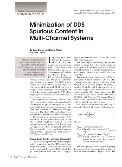
Implement<strong>in</strong>g a Direct<br />
This article reviews the Digital Synthesizer<br />
mechanisms that result <strong>in</strong> (<strong>DDS</strong>) IC <strong>in</strong> a new<br />
the generation <strong>of</strong> spurs design can be a daunt<strong>in</strong>g<br />
<strong>in</strong> <strong>DDS</strong> systems, and shows task. Many times, the<br />
how to select the best <strong>DDS</strong> is looked upon as a<br />
clock frequency to “noise generator” and the<br />
m<strong>in</strong>imize those spurs. unfortunate designer is<br />
left to deal with whatever<br />
output spectrum the <strong>DDS</strong> presents after the<br />
basic design is complete. The <strong>DDS</strong> is <strong>in</strong> a<br />
unique class <strong>of</strong> ICs that jo<strong>in</strong>s the once separate<br />
worlds <strong>of</strong> digital and RF circuit design.<br />
Despite these challenges, the designer can<br />
predict the output spectrum <strong>of</strong> the <strong>DDS</strong> with a<br />
high degree <strong>of</strong> accuracy with the knowledge <strong>of</strong><br />
several basic concepts.<br />
Two topics will be covered. The first topic<br />
will be an analysis that can be completed by<br />
the designer to predict the spurious signals<br />
that result from harmonic remapp<strong>in</strong>g <strong>in</strong> the<br />
<strong>DDS</strong> given a predef<strong>in</strong>ed <strong>DDS</strong> clock and output<br />
frequency. The ideal <strong>DDS</strong> clock choice for a<br />
given output frequency will also be discussed.<br />
The second topic will build on the first by<br />
exam<strong>in</strong><strong>in</strong>g a channelized frequency source<br />
where a <strong>DDS</strong> would more likely be used. A<br />
sample design and algorithm will be stepped<br />
through to show how an optimal <strong>DDS</strong> clock<br />
frequency can be chosen based on designated<br />
output channel frequencies, local oscillator<br />
(LO) choice, and filter<strong>in</strong>g.<br />
Output Spurs Due to Harmonic Remapp<strong>in</strong>g<br />
One <strong>of</strong> the most prom<strong>in</strong>ent sources <strong>of</strong> spurs<br />
<strong>in</strong> the output spectrum <strong>of</strong> a <strong>DDS</strong> is due to harmonic<br />
remapp<strong>in</strong>g. These spurs are essentially<br />
the harmonics <strong>of</strong> the desired <strong>DDS</strong> output that<br />
get “transplanted” back <strong>in</strong>to the 1st Nyquist<br />
zone, which extends from 0 Hz to half <strong>of</strong> the<br />
<strong>DDS</strong> clock frequency.<br />
The first step <strong>in</strong> calculat<strong>in</strong>g the spurious<br />
output spectrum due to harmonic remapp<strong>in</strong>g<br />
is to create a list <strong>of</strong> harmonics <strong>of</strong> the desired<br />
output frequency. It is usually best to calculate<br />
out as many harmonics as possible, the more<br />
the better.<br />
The next step is to calculate which Nyquist<br />
zone each <strong>of</strong> the harmonics falls <strong>in</strong>to. The<br />
Nyquist zones span <strong>in</strong>teger multiples <strong>of</strong> the<br />
Nyquist frequency. The Nyquist frequency is<br />
equal to 1/2 <strong>of</strong> the clock frequency, and therefore<br />
each Nyquist zone starts or stops at an<br />
<strong>in</strong>teger multiple <strong>of</strong> the Nyquist frequency. The<br />
first Nyquist zone would extend from 0 Hz to<br />
1/2 <strong>of</strong> the clock frequency. The second Nyquist<br />
zone would extend from 1/2 the clock frequency<br />
to the clock frequency, and so on.<br />
For a given output harmonic, the Nyquist<br />
zone <strong>in</strong>to which it falls may be calculated as:<br />
where:<br />
⎛ F<br />
Zone = ceil ⎜<br />
⎝ F<br />
Harm<br />
Nyquist<br />
⎞<br />
⎟<br />
⎠<br />
(1)<br />
F Harm<br />
= harmonic frequency.<br />
Zone = Nyquist zone <strong>in</strong>to which F harmonic<br />
falls<br />
F Nyquist<br />
= Nyquist frequency (F CLK<br />
/2)<br />
Ceil = ceil<strong>in</strong>g function. This function<br />
rounds to the next higher <strong>in</strong>teger<br />
toward positive <strong>in</strong>f<strong>in</strong>ity.<br />
The remapp<strong>in</strong>g <strong>of</strong> the harmonic frequency<br />
depends on if the harmonic falls with<strong>in</strong> an<br />
even or odd numbered Nyquist zone. The<br />
18 High Frequency Electronics
High Frequency Design<br />
MINIMIZING <strong>DDS</strong> SPURS<br />
Algorithm for Predict<strong>in</strong>g Output Spurs<br />
1. Create a list <strong>of</strong> “N” harmonic frequencies <strong>of</strong> the desired <strong>DDS</strong> output frequency,<br />
F Out :<br />
F<br />
Harm<br />
= n⋅F<br />
Out<br />
, where n is an <strong>in</strong>teger rang<strong>in</strong>g from 1 to N.<br />
2. For each harmonic frequency, calculate the Nyquist Zone <strong>in</strong>to which it<br />
falls:<br />
⎛ F<br />
Zone = ceil ⎜<br />
⎝ F<br />
Harm<br />
Nyquist<br />
⎞<br />
⎟<br />
⎠<br />
3. If the harmonic lies <strong>in</strong> an odd Nyquist Zone (i.e., Zone 1, 3, 5, 7 ...) then<br />
calculate the remapped harmonic frequency as follows:<br />
⎛<br />
F = F − floor Zone ⎞<br />
F<br />
⎝<br />
⎜<br />
⎠<br />
⎟ ⋅<br />
2<br />
remap Harm Clk<br />
OR, if the harmonic lies <strong>in</strong> an even Nyquist Zone (i.e., Zone 2, 4, 6, 8 ...)<br />
then calculate the remapped harmonic frequency as follows:<br />
F<br />
remapped frequency may be calculated as follows:<br />
If the harmonic falls with<strong>in</strong> an even numbered<br />
Nyquist zone:<br />
Zone<br />
Fremap = ⋅ F<br />
Clk<br />
− F<br />
Harm<br />
(2)<br />
2<br />
If the harmonic falls with<strong>in</strong> an odd numbered Nyquist<br />
zone:<br />
F = F<br />
⎛<br />
floor Zone ⎞<br />
−<br />
F<br />
⎝<br />
⎜<br />
⎠<br />
⎟ ⋅<br />
2<br />
where:<br />
Floor = floor function. This function rounds to the next<br />
lower <strong>in</strong>teger toward m<strong>in</strong>us <strong>in</strong>f<strong>in</strong>ity.<br />
It is very important to note that there are discrete<br />
locations that spurs can appear <strong>in</strong> the <strong>DDS</strong> output spectrum.<br />
These spur locations are located at <strong>in</strong>teger multiples<br />
<strong>of</strong> the greatest common divisor between the <strong>DDS</strong><br />
clock frequency and the desired output frequency, or:<br />
∆ spur<br />
gcd F Clk<br />
, F Out<br />
where:<br />
Zone<br />
= ⋅ F − F<br />
2<br />
remap Clk Harm<br />
Figure 1 · Harmonic remapp<strong>in</strong>g algorithm.<br />
remap Harm Clk<br />
= ( )<br />
∆ spur<br />
= frequency spac<strong>in</strong>g <strong>of</strong> spurs due to harmonic<br />
remapp<strong>in</strong>g<br />
F Clk<br />
= <strong>DDS</strong> clock frequency<br />
F Out<br />
= fundamental <strong>DDS</strong> output frequency<br />
gcd = greatest common divisor function.<br />
(3)<br />
(4)<br />
Figure 2 · Simulated results for 99.25 MHz spectrum.<br />
There is a unique case where no spurs will appear <strong>in</strong><br />
the output spectrum. This occurs when the clock frequency<br />
is an <strong>in</strong>teger multiple <strong>of</strong> the output frequency. When<br />
the clock is an <strong>in</strong>teger multiple <strong>of</strong> the output, the result <strong>of</strong><br />
Equation 4 (the spur spac<strong>in</strong>g) is equal to the output frequency.<br />
Therefore, the output spectrum will conta<strong>in</strong> only<br />
harmonics <strong>of</strong> the output frequency.<br />
The amplitude <strong>of</strong> the spurs can not be accurately predicted<br />
due to the unique non-l<strong>in</strong>earity’s <strong>in</strong> the <strong>DDS</strong> output<br />
DACs, but it follows that the higher order harmonics<br />
will have a lower amplitude relative to the lower order<br />
harmonics.<br />
Simulation<br />
A simulation was run <strong>in</strong> MatLab us<strong>in</strong>g a <strong>DDS</strong> clock<br />
frequency <strong>of</strong> 378 MHz and a desired output <strong>of</strong> 92.25 MHz.<br />
Given this, it can be calculated that spurs could appear at<br />
2.25 MHz <strong>in</strong>tervals from the desired output frequency <strong>of</strong><br />
92.25 MHz. The simulation shown below is ignor<strong>in</strong>g all<br />
spurs that fall outside <strong>of</strong> 92.25 MHz ±25 MHz. Also, the<br />
harmonics were calculated out to the 100th harmonic.<br />
The remapped frequencies that fall with<strong>in</strong> ±25 MHz <strong>of</strong><br />
92.25 MHz are listed <strong>in</strong> Table 1. Figure 2 shows an<br />
approximation <strong>of</strong> the <strong>DDS</strong> output spectrum. The amplitudes<br />
are only approximations that are based on the<br />
order <strong>of</strong> the harmonic to which it is related.<br />
Measurements<br />
The AD9959 evaluation board was used <strong>in</strong> this test.<br />
The clock for the <strong>DDS</strong> was provided by a signal generator<br />
with the output set to 378 MHz at 0 dBm. The <strong>DDS</strong> output<br />
spectrum was captured on an Agilent E4440A spectrum<br />
analyzer, see Figure 3. The span <strong>of</strong> the analyzer was<br />
set to 50 MHz so that it equals the span seen <strong>in</strong> Figure 2.<br />
20 High Frequency Electronics
High Frequency Design<br />
MINIMIZING <strong>DDS</strong> SPURS<br />
Delta Frequency (MHz) Harmonic #<br />
–24.75 54<br />
–22.5 73<br />
–22.5 95<br />
–20.25 32<br />
–18 9<br />
–15.75 50<br />
–13.5 77<br />
–13.5 91<br />
–11.25 36<br />
–9 5<br />
–6.75 46<br />
–4.5 81<br />
–4.5 87<br />
–2.25 40<br />
0 1<br />
2.25 42<br />
4.5 83<br />
4.5 85<br />
6.75 44<br />
9 3<br />
11.25 38<br />
13.5 79<br />
13.5 89<br />
15.75 48<br />
18 7<br />
20.25 34<br />
22.5 75<br />
22.5 93<br />
24.75 52<br />
Table 1 · List <strong>of</strong> spurious frequencies due to harmonic<br />
remapp<strong>in</strong>g, from the MatLab simulation.<br />
Figure 3 · 92.25 MHz spectrum analyzer measurement.<br />
Frequency Amplitude Source<br />
Offset (MHz) (dBm) Harmonic #<br />
–22.5 –87 73rd & 95th<br />
–18 –86 9th<br />
–13.5 –89 77th & 91st<br />
–9 –82 5th<br />
–4.5 –86 81st & 87th<br />
4.5 –86 83rd & 85th<br />
9 –75 3rd<br />
13.5 –85 79th & 89th<br />
18 –87 7th<br />
22.5 –89 75th & 93rd<br />
Table 2 · Measured spectrum results.<br />
There are five major spurs (spurs above –90 dBm) visible<br />
on both sides <strong>of</strong> the carrier. Table 2 lists the spurs harmonic<br />
relationship to the carrier as well as approximate<br />
amplitude.<br />
Choos<strong>in</strong>g Best Clock for <strong>Multi</strong>ple Output<br />
Frequencies<br />
The previous method is sufficient as long as the<br />
designer is constra<strong>in</strong>ed to us<strong>in</strong>g a given clock and output<br />
frequency. However, the designer is <strong>of</strong>ten faced with a<br />
more difficult problem <strong>of</strong> hav<strong>in</strong>g to choose a clock that<br />
m<strong>in</strong>imizes spurious levels over several output frequencies,<br />
or channels. The choice <strong>of</strong> LO frequency and filter<strong>in</strong>g<br />
bandwidth must also be taken <strong>in</strong>to account. A more<br />
detailed algorithm is required to identify the best possible<br />
<strong>DDS</strong> clock frequency.<br />
The “best” <strong>DDS</strong> clock frequency is one that produces<br />
the m<strong>in</strong>imum amount <strong>of</strong> spurs on all desired output frequencies.<br />
The first step is for the designer to choose an<br />
appropriate <strong>DDS</strong> chip and identify the required output<br />
frequencies. After this is done, the maximum and m<strong>in</strong>imum<br />
<strong>DDS</strong> clock frequencies may be identified. The maximum<br />
allowable <strong>DDS</strong> clock frequency is dictated by the<br />
<strong>DDS</strong> manufacturers data sheet, and the m<strong>in</strong>imum <strong>DDS</strong><br />
clock frequency should be greater than twice the highest<br />
desired output frequency. A good rule <strong>of</strong> thumb is keep the<br />
highest desired output frequency equal to at most 40% <strong>of</strong><br />
the clock frequency, or:<br />
FOut<br />
FClkMIN<br />
≥ (5)<br />
040 .<br />
Now that the m<strong>in</strong>imum and maximum <strong>DDS</strong> clock frequencies<br />
are def<strong>in</strong>ed, the designer can now beg<strong>in</strong> the process<br />
<strong>of</strong> choos<strong>in</strong>g the best clock for their application.<br />
Obviously, there are an <strong>in</strong>f<strong>in</strong>ite number <strong>of</strong> possible clock<br />
frequencies with<strong>in</strong> the <strong>DDS</strong> clock limits, but the designer<br />
can quickly reduce the possible clock frequencies by perform<strong>in</strong>g<br />
a simple algorithm.<br />
22 High Frequency Electronics
High Frequency Design<br />
MINIMIZING <strong>DDS</strong> SPURS<br />
Spur Weight<strong>in</strong>g Factors<br />
Figure 4 · Remapped harmonic matrices for all output<br />
and clock frequencies.<br />
We know from Equation 4 that spurs can only exist at<br />
certa<strong>in</strong> <strong>in</strong>tervals from the fundamental and that the<br />
<strong>in</strong>terval is equal to the greatest common divisor (GCD) <strong>of</strong><br />
the fundamental and the clock. The largest possible <strong>in</strong>terval<br />
for multiple output frequencies would be equal to the<br />
GCD <strong>of</strong> all <strong>of</strong> the output frequencies, and the only clock<br />
frequencies that can produce this spac<strong>in</strong>g for all required<br />
output frequencies are ones that are evenly divisible by<br />
this spac<strong>in</strong>g. Therefore, a list <strong>of</strong> clock frequencies can be<br />
made, start<strong>in</strong>g at the m<strong>in</strong>imum (as def<strong>in</strong>ed <strong>in</strong> Equation 5)<br />
stepp<strong>in</strong>g at <strong>in</strong>tervals equal to the GCD <strong>of</strong> the output frequencies<br />
and end<strong>in</strong>g at the maximum <strong>DDS</strong> clock frequency.<br />
An example is shown below:<br />
Example: A <strong>DDS</strong> is chosen that has a maximum clock<br />
frequency <strong>of</strong> 400 MHz. Four output frequencies are<br />
desired: 120, 125, 130, and 140 MHz. The <strong>DDS</strong> m<strong>in</strong>imum<br />
clock frequency should be no less than 350 MHz, as<br />
def<strong>in</strong>ed by Equation 5. The GCD <strong>of</strong> the output frequencies<br />
is 5 MHz. Therefore, the number <strong>of</strong> best case clock frequencies<br />
are now reduced to eleven: 350 to 400 MHz <strong>in</strong><br />
steps <strong>of</strong> 5 MHz.<br />
Therefore, <strong>in</strong> order to reduce the number <strong>of</strong> potential<br />
spurs <strong>in</strong> a given bandwidth for multiple output frequencies,<br />
the clock frequency should be chosen so that it is<br />
evenly divisible by the GCD <strong>of</strong> all <strong>of</strong> the output frequencies.<br />
Now that the possible clock frequencies have been<br />
reduced significantly, the rema<strong>in</strong><strong>in</strong>g frequencies can be<br />
“ranked” <strong>in</strong> terms <strong>of</strong> which ones produce the fewest and<br />
lowest amplitude spurs for all the desired output frequencies<br />
<strong>in</strong> a given bandwidth. This process is best<br />
implemented <strong>in</strong> s<strong>of</strong>tware (e.g. MatLab, MathCad, Excel).<br />
In order to rank each clock frequency, it is necessary to<br />
identify the factors that will <strong>in</strong>fluence the number and<br />
amplitude <strong>of</strong> the spurs <strong>in</strong> the output spectrum. There are<br />
three primary weight<strong>in</strong>g factors that should be applied to<br />
all spurs <strong>in</strong> order to properly rank the clock frequency.<br />
These factors give a greater weight to less desirable<br />
spurs.<br />
1. Order <strong>of</strong> harmonic caus<strong>in</strong>g spur (lower order harmonics<br />
should be given greater weight than higher<br />
order harmonics)<br />
2. Whether the spur comes from an even or odd harmonic<br />
(an odd order harmonic spur should be given<br />
greater weight than an even order harmonic spur)<br />
3. The frequency difference <strong>of</strong> each spur from the<br />
desired output (spurs located closer to the fundamental<br />
should be given greater weight than spurs<br />
further away)<br />
The remapp<strong>in</strong>g algorithm must be completed for each<br />
output frequency at every potential ‘best-case’ clock frequency.<br />
This will produce an N × M matrix as seen <strong>in</strong><br />
Figure 4. Each <strong>of</strong> the items labeled “A” <strong>in</strong> the figure is a<br />
matrix result<strong>in</strong>g from the remapp<strong>in</strong>g algorithm performed<br />
on the clock and output frequencies. For simplicity,<br />
these sub-matrices should conta<strong>in</strong> two rows, one for<br />
the remapped frequency and one for the order <strong>of</strong> the harmonic<br />
that produced it. The number <strong>of</strong> columns <strong>in</strong> these<br />
matrices will be equal to the maximum harmonic order<br />
that is set <strong>in</strong> the remapp<strong>in</strong>g algorithm (refer to Step 1 <strong>in</strong><br />
Figure 1).<br />
Each one <strong>of</strong> the sub-matrices can be reduced by elim<strong>in</strong>at<strong>in</strong>g<br />
any spurs that fall outside <strong>of</strong> a given bandwidth<br />
around the desired output frequency (i.e. spurs that may<br />
be filtered <strong>of</strong>f easily by external filter<strong>in</strong>g). This may also<br />
help to speed up the process for larger numbers <strong>of</strong> clock<br />
and output frequencies.<br />
A weight should now be calculated for each sub-matrix<br />
“A.” For each spur <strong>in</strong> each sub-matrix “A,” the three<br />
weight<strong>in</strong>g methods listed above should be applied. The<br />
three weights will be multiplied together to produce a net<br />
weight for each spur <strong>in</strong> each sub-matrix “A.” Now all <strong>of</strong><br />
the spurs’ weights can be summed <strong>in</strong> each sub-matrix “A.”<br />
This produces an <strong>in</strong>dividual weight for each sub-matrix<br />
“A.” To get a net weight for each clock frequency (columns<br />
<strong>in</strong> Figure 4), the weights <strong>of</strong> all the matrices <strong>in</strong> a given column<br />
will be summed.<br />
Now each clock frequency will have a weight, or rank,<br />
associated with it. These ranks can now be used to determ<strong>in</strong>e<br />
the best choice <strong>of</strong> clock frequency.<br />
The entire weight<strong>in</strong>g procedure for a given clock frequency<br />
can be def<strong>in</strong>ed as:<br />
N P<br />
⎡<br />
3<br />
⎡<br />
WCLKm ∑ ⎢∑<br />
⎢∏<br />
Wk Spurj<br />
i=<br />
1 ⎣ j=<br />
1 ⎣ k=<br />
1<br />
m = 12 , ... M<br />
where:<br />
( )<br />
< Aim<br />
, ><br />
= ( )<br />
⎤⎤<br />
⎥⎥<br />
⎦⎦<br />
(6)<br />
24 High Frequency Electronics
High Frequency Design<br />
MINIMIZING <strong>DDS</strong> SPURS<br />
GCD (MHz) <strong>of</strong> Clock Frequency & Output Frequency<br />
Clock Score 130 135 140 145 150<br />
Freq. MHz MHz MHz MHz MHz<br />
(MHz)<br />
490 2.4535 10 5 70 5 10<br />
495 2.4899 5 45 5 5 15<br />
450 2.5093 10 45 10 5 150<br />
500 2.5145 10 5 20 5 50<br />
480 2.5557 10 15 20 5 30<br />
390 2.6225 130 15 10 5 30<br />
420 2.8318 10 15 140 5 30<br />
435 3.2841 5 15 5 145 15<br />
405 3.7357 5 135 5 5 15<br />
375 3.7621 5 15 5 5 75<br />
465 3.8162 5 15 5 5 15<br />
460 3.8634 10 5 20 5 10<br />
475 3.8961 5 5 5 5 25<br />
485 3.9530 5 5 5 5 5<br />
470 4.0415 10 5 10 5 10<br />
455 4.2389 65 5 35 5 5<br />
380 4.7060 10 5 20 5 10<br />
400 5.5705 10 5 20 5 50<br />
440 5.8586 10 5 20 5 10<br />
430 5.9504 10 5 10 5 10<br />
410 6.1418 10 5 10 5 10<br />
385 6.2909 5 5 35 5 5<br />
445 6.2996 5 5 5 5 5<br />
425 6.3264 5 5 5 5 25<br />
395 6.6377 5 5 5 5 5<br />
415 6.7361 5 5 5 5 5<br />
Figure 5 · 130 MHz simulated results—490 MHz (left)<br />
and 415 MHz (right) <strong>DDS</strong> clock.<br />
Figure 6 · 135 MHz simulated results—490 MHz (left)<br />
and 415 MHz (right) <strong>DDS</strong> clock.<br />
Table 3 · Clock frequency results and scores.<br />
Spur > j<br />
Figure 8 · 145 MHz simulated results—490 MHz (left)<br />
and 415 MHz (right) <strong>DDS</strong> clock.<br />
Figure 9 · 150 MHz simulated results—490 MHz (left)<br />
and 415 MHz (right) <strong>DDS</strong> clock.<br />
the peak <strong>of</strong> the spur is the order <strong>of</strong> the harmonic that created<br />
it.<br />
It should be noted that the amplitudes <strong>of</strong> the spurs <strong>in</strong><br />
the follow<strong>in</strong>g plots are not to scale. The amplitude was<br />
based on the order <strong>of</strong> the harmonic that created it, thus<br />
2nd and 3rd order harmonic spurs have the highest<br />
amplitudes. The absolute amplitudes <strong>of</strong> the spurs are difficult<br />
to predict accurately.<br />
Measurements<br />
Figures 10 through 14 show the<br />
measured results. Each figure displays<br />
two versions <strong>of</strong> the spectrum <strong>of</strong><br />
one <strong>of</strong> the output channels (130, 135,<br />
140, 145 or 150 MHz). The spectrum<br />
plots on the left were produced us<strong>in</strong>g<br />
the clock frequency with the lowest<br />
(best) score which was 490 MHz. The<br />
spectrum plots on the right were produced<br />
us<strong>in</strong>g the clock frequency with<br />
the highest (worst) score, which was<br />
415 MHz. It can be seen that the<br />
plots on the left are generally ‘better’<br />
than those on the right with regards<br />
to number and amplitude <strong>of</strong> spurs.<br />
tolerated, an optimal clock frequency can be found by<br />
manually sweep<strong>in</strong>g the clock to f<strong>in</strong>d the frequency that<br />
result <strong>in</strong> no low order (2nd through maybe 10th) harmonics<br />
<strong>in</strong> the passband <strong>of</strong> each <strong>of</strong> the channels.<br />
Conclusion<br />
The designer faces many challenges when implement<strong>in</strong>g<br />
a <strong>DDS</strong> design. However, by understand<strong>in</strong>g the orig<strong>in</strong><br />
<strong>of</strong> <strong>DDS</strong> spurs their effects can be m<strong>in</strong>imized. The concept<br />
<strong>of</strong> harmonic remapp<strong>in</strong>g was <strong>in</strong>troduced and analysis tech-<br />
Design Considerations<br />
In a multi-channel system the use<br />
<strong>of</strong> the GCD method <strong>in</strong> the <strong>DDS</strong> clock<br />
selection algorithm ensures that all<br />
spurs will be the maximum distance<br />
from the center frequency and those<br />
that are present are the lowest possible.<br />
This should maximize the performance<br />
<strong>of</strong> IF filter<strong>in</strong>g. However, spurs<br />
that are present will most likely be<br />
located at the center frequency <strong>of</strong> the<br />
<strong>of</strong>f channels, which <strong>in</strong> the presence <strong>of</strong><br />
other systems may result <strong>in</strong> IF <strong>in</strong>terference.<br />
If this <strong>in</strong>terference cannot be
High Frequency Design<br />
MINIMIZING <strong>DDS</strong> SPURS<br />
Figure 10 · 130 MHz output measured—490 MHz (left)<br />
and 415 MHz (right) <strong>DDS</strong> clock.<br />
Figure 11 · 135 MHz output measured—490 MHz (left)<br />
and 415 MHz (right) <strong>DDS</strong> clock.<br />
Figure 12 · 140 MHz output measured—490 MHz (left)<br />
and 415 MHz (right) <strong>DDS</strong> clock.<br />
Figure 13 · 145 MHz output measured—490 MHz (left)<br />
and 415 MHz (right) <strong>DDS</strong> clock.<br />
niques were demonstrated that allow the designer to<br />
accurately predict the harmonic content <strong>of</strong> the <strong>DDS</strong> output<br />
signal.<br />
It was then shown how these analysis techniques<br />
could be extended to choose a clock frequency that m<strong>in</strong>imizes<br />
the spurious content <strong>of</strong> several frequency outputs<br />
<strong>in</strong> a multi-channel system. After apply<strong>in</strong>g the harmonic<br />
remapp<strong>in</strong>g analysis to f<strong>in</strong>d the spurious content <strong>of</strong> each<br />
<strong>DDS</strong> clock/frequency output comb<strong>in</strong>ation, a weight<strong>in</strong>g<br />
function was applied to assign a relative score to the comb<strong>in</strong>ation.<br />
By simply choos<strong>in</strong>g the m<strong>in</strong>imum sum <strong>of</strong> the<br />
scores for each <strong>DDS</strong> clock matrix column, the preferred<br />
clock frequency can be found. This process can easily be<br />
automated <strong>in</strong> several mathematical analysis tools. While<br />
several design considerations must be taken <strong>in</strong>to account<br />
the designer has been provided with a powerful analysis<br />
tool to successfully complete a <strong>DDS</strong> implementation.<br />
Bibliography<br />
1. “A Technical Tutorial on Digital Signal Synthesis,”<br />
Analog Devices, 1999.<br />
2. Nicholas, Henry T., and Samueli, Henry, “An<br />
Analysis <strong>of</strong> the Output Spectrum <strong>of</strong> Direct Digital<br />
Frequency Synthesizers <strong>in</strong> the Presence <strong>of</strong> Phase-<br />
Accumulator Truncation,” 41st Annual Frequency Control<br />
Symposium, 1987, pp/ 495-502.<br />
3. AD9959 Data Sheet and Evaluation Board.<br />
4. MatLab S<strong>of</strong>tware.<br />
Figure 14 · 150 MHz output measured—490 MHz (left)<br />
and 415 MHz (right) <strong>DDS</strong> clock.<br />
Author Information<br />
Ryan Groulx received an A.S. degree <strong>in</strong> Avionics<br />
Technology from Embry-Riddle Aeronautical University<br />
<strong>in</strong> 1995a B.S.E.E. from University <strong>of</strong> South Florida <strong>in</strong><br />
1997 and a M.S.E.E. from Florida Institute <strong>of</strong> Technology<br />
<strong>in</strong> 2000. Ryan is a Senior Electrical Eng<strong>in</strong>eer at Rockwell<br />
Coll<strong>in</strong>s <strong>in</strong> the Weather Radar program. He can be reached<br />
by email at rcgroulx@rockwellcoll<strong>in</strong>s.com or by phone at<br />
321-953-1757.<br />
Shawn Mason received his B.S.E.E. from the Georgia<br />
Institute <strong>of</strong> Technology <strong>in</strong> 2002 and is pursu<strong>in</strong>g his<br />
M.S.E.E at the Florida Institute <strong>of</strong> Technology. Shawn is<br />
an Electrical Eng<strong>in</strong>eer at Rockwell Coll<strong>in</strong>s <strong>in</strong> the Weather<br />
Radar program. He can be reached by email at smmason@rockwellcoll<strong>in</strong>s.com<br />
or by phone at 321-674-5389.<br />
28 High Frequency Electronics