Fabric Improvements for Energy Efficiency in ... - Historic Scotland
Fabric Improvements for Energy Efficiency in ... - Historic Scotland
Fabric Improvements for Energy Efficiency in ... - Historic Scotland

Create successful ePaper yourself
Turn your PDF publications into a flip-book with our unique Google optimized e-Paper software.
1<br />
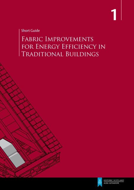
Short Guide<br />
<strong>Fabric</strong> <strong>Improvements</strong><br />
<strong>for</strong> <strong>Energy</strong> <strong>Efficiency</strong> <strong>in</strong><br />
Traditional Build<strong>in</strong>gs
<strong>Fabric</strong> improvements <strong>for</strong> energy efficiency <strong>in</strong> traditional build<strong>in</strong>gs<br />
Contents<br />
1. Introduction<br />
2<br />
2. Pr<strong>in</strong>ciples<br />
5<br />
3. <strong>Fabric</strong> Upgrades<br />
7<br />
3.1 Roofs and Lofts<br />
7<br />
3.2 Floors<br />
11<br />
3.3 W<strong>in</strong>dows<br />
13<br />
3.4 Doors<br />
18<br />
3.5 Walls<br />
20<br />
3.6 Chimneys and Flues<br />
27<br />
4 . Conclusion<br />
28<br />
5. Contacts and Further Read<strong>in</strong>g<br />
29<br />
6. Glossary<br />
32
<strong>Fabric</strong> improvements <strong>for</strong> energy efficiency <strong>in</strong> traditional build<strong>in</strong>gs<br />
1. Introduction<br />
1. Introduction<br />
The Climate Change (<strong>Scotland</strong>) Act 2009 commits <strong>Scotland</strong> to some of the<br />
most ambitious carbon reduction targets <strong>in</strong> the world, <strong>in</strong>clud<strong>in</strong>g the reduction<br />
of greenhouse gas emissions by 42% by 2020; and 80% by 2050 from 1990<br />
levels (Scottish Government 2009). With around 40% of <strong>Scotland</strong>’s total carbon<br />
emissions com<strong>in</strong>g from domestic energy consumption and almost 20% of all<br />
build<strong>in</strong>gs be<strong>in</strong>g traditionally constructed, improv<strong>in</strong>g energy efficiency <strong>in</strong> these<br />
build<strong>in</strong>gs is key to meet<strong>in</strong>g the national carbon reduction commitments. As a<br />
government agency, <strong>Historic</strong> <strong>Scotland</strong> has been mandated to take the lead <strong>in</strong><br />
research and guidance to improve energy efficiency <strong>in</strong> traditional and historic<br />
build<strong>in</strong>gs, as laid out <strong>in</strong> The <strong>Energy</strong> <strong>Efficiency</strong> Action Plan (Scottish Government 2010),<br />
and further articulated <strong>in</strong> the <strong>Historic</strong> <strong>Scotland</strong> Climate Change Action<br />
Plan (<strong>Historic</strong> <strong>Scotland</strong> 2012).<br />
Traditional build<strong>in</strong>gs are generally considered to be those built be<strong>for</strong>e 1919<br />
us<strong>in</strong>g load-bear<strong>in</strong>g mass masonry walls, with pitched roofs covered <strong>in</strong> slate or<br />
another natural roof<strong>in</strong>g material. W<strong>in</strong>dows are generally s<strong>in</strong>gle glazed with<br />
timber frames, often <strong>in</strong> the slid<strong>in</strong>g sash and case pattern, and the build<strong>in</strong>gs have<br />
<strong>in</strong>ternal timber and lime plaster f<strong>in</strong>ishes and passive ventilation systems. The term<br />
‘traditional build<strong>in</strong>gs’ covers a broad range of build<strong>in</strong>gs, not just those referred to<br />
as ‘listed’, ‘historic’ or ‘heritage’. <strong>Scotland</strong> has around 400,000 pre-1919 build<strong>in</strong>gs,<br />
compris<strong>in</strong>g approximately 20% of the total build<strong>in</strong>g stock, approximately 47,000<br />
of which are listed. Such structures <strong>in</strong>clude cottages, villas, public build<strong>in</strong>gs and<br />
commercial build<strong>in</strong>gs as well as tenements, which are prevalent <strong>in</strong> the Central<br />
Belt of <strong>Scotland</strong> (Fig. 1).<br />
This guide presents a series of practical solutions to improv<strong>in</strong>g energy efficiency <strong>in</strong><br />
traditional and historic build<strong>in</strong>gs, through a range of specific fabric improvement<br />
measures to different elements of a build<strong>in</strong>g (specifically roofs and lofts, floors,<br />
w<strong>in</strong>dows and doors, walls and chimneys). Crucially, the methods outl<strong>in</strong>ed <strong>in</strong><br />
this report allow the build<strong>in</strong>g to cont<strong>in</strong>ue to function <strong>in</strong> terms of ma<strong>in</strong>ta<strong>in</strong><strong>in</strong>g<br />
ventilation and moisture permeability, whilst reta<strong>in</strong><strong>in</strong>g historic character and<br />
m<strong>in</strong>imis<strong>in</strong>g the visual impact of the changes. The examples given are based<br />
on a series of trials and pilot projects undertaken or managed by <strong>Historic</strong><br />
<strong>Scotland</strong> <strong>in</strong> which energy sav<strong>in</strong>g measures were trialled at a variety of traditional<br />
properties throughout <strong>Scotland</strong>, <strong>in</strong>clud<strong>in</strong>g detached rural cottages, tenement<br />
flats, townhouses and public build<strong>in</strong>gs dat<strong>in</strong>g from the 18th, 19th and early 20th<br />
centuries. The results of these projects are published as a series of Refurbishment<br />
Case Studies available from the <strong>Historic</strong> <strong>Scotland</strong> website, where the specific<br />
measures are described <strong>in</strong> more detail. Attention is also drawn to the <strong>Historic</strong><br />
<strong>Scotland</strong> Technical Papers (also available on our website) which provide detailed<br />
<strong>in</strong><strong>for</strong>mation on relevant technical issues such as U-value measurements <strong>in</strong><br />
traditional build<strong>in</strong>gs, thermal per<strong>for</strong>mance of traditional w<strong>in</strong>dows, energy<br />
modell<strong>in</strong>g and thermal com<strong>for</strong>t.<br />
2
<strong>Fabric</strong> improvements <strong>for</strong> energy efficiency <strong>in</strong> traditional build<strong>in</strong>gs<br />
01<br />
This guide does not aim to provide detailed specifications <strong>for</strong> work to be<br />
undertaken; rather it seeks to give <strong>in</strong>dicative details of possible approaches and<br />
potential results. Not all the measures described will be appropriate or possible<br />
<strong>in</strong> every case and each situation should be assessed on its own merit with the<br />
most relevant measures taken based on the specific circumstances, especially the<br />
historic significance of the build<strong>in</strong>g or fabric element. Such considerations should<br />
always be kept <strong>in</strong> m<strong>in</strong>d and balanced aga<strong>in</strong>st possibly more effective sav<strong>in</strong>gs from<br />
demand side reductions. The research to date suggests that there is likely to be<br />
a technique suitable to improve the thermal per<strong>for</strong>mance of most traditional<br />
build<strong>in</strong>gs without adversely affect<strong>in</strong>g their fabric and character.<br />
Fig. 1 Traditionally constructed<br />
houses <strong>in</strong> South West <strong>Scotland</strong>.<br />
Whilst this guidance focuses on <strong>in</strong>terventions to the fabric of build<strong>in</strong>gs and the<br />
upgrades described are broadly <strong>in</strong> a hierarchy that reflects ease and cost of the<br />
measures, such work should only beg<strong>in</strong> after other methods of reduc<strong>in</strong>g energy<br />
demand have been undertaken. <strong>Improvements</strong> to services such as heat<strong>in</strong>g<br />
systems and light<strong>in</strong>g, and occupier behaviour, will have a significant impact on<br />
reduc<strong>in</strong>g energy use <strong>in</strong> a build<strong>in</strong>g. Furthermore, the field of energy efficiency<br />
improvements is a rapidly evolv<strong>in</strong>g one, and new solutions and approaches are<br />
likely to emerge over the next few years. Many of the <strong>Historic</strong> <strong>Scotland</strong> pilot<br />
projects described are subject to on-go<strong>in</strong>g monitor<strong>in</strong>g, and further results and<br />
updates will be published <strong>in</strong> new versions of this guide and updates to the<br />
Refurbishment Case Studies.<br />
3
<strong>Fabric</strong> improvements <strong>for</strong> energy efficiency <strong>in</strong> traditional build<strong>in</strong>gs<br />
1. Introduction<br />
The measures described <strong>in</strong> this guide are likely to be relevant to most traditional<br />
build<strong>in</strong>gs and some historic ones; however where a build<strong>in</strong>g is listed or <strong>in</strong> a<br />
conservation area there may be restrictions on work or additional consent<br />
processes which will apply. Similarly some procedures may require a build<strong>in</strong>g<br />
warrant. Further <strong>in</strong><strong>for</strong>mation can be found <strong>in</strong> Build<strong>in</strong>g Standards Division Technical<br />
Handbooks or by contact<strong>in</strong>g local authority Build<strong>in</strong>g Standards Departments. In<br />
all cases it is advisable to contact the local authority Plann<strong>in</strong>g Department prior<br />
to start<strong>in</strong>g any work to establish whether plann<strong>in</strong>g permission, listed build<strong>in</strong>g<br />
consent or a build<strong>in</strong>g warrant is required.<br />
Throughout this publication the effectiveness of specific <strong>in</strong>sulation measures is<br />
<strong>in</strong>dicated us<strong>in</strong>g U-values. A U-value is the amount of heat lost (<strong>in</strong> Watts) per square<br />
metre of material at a temperature difference of one degree (measured <strong>in</strong> Kelv<strong>in</strong>).<br />
In build<strong>in</strong>g fabric work, the lower the U-value, the better the <strong>in</strong>sulation or element<br />
is per<strong>for</strong>m<strong>in</strong>g thermally. All the U-values presented here are actual measurements<br />
(expressed as W/m 2 K) from the <strong>Historic</strong> <strong>Scotland</strong> energy efficiency pilot projects<br />
(Refurbishment Case Studies). More details on U-values <strong>in</strong> traditional build<strong>in</strong>gs can<br />
be found <strong>in</strong> <strong>Historic</strong> <strong>Scotland</strong> Technical Papers 1, 2 and 10: Thermal Per<strong>for</strong>mance<br />
of Traditional W<strong>in</strong>dows, In situ U-value Measurements <strong>in</strong> Traditional Build<strong>in</strong>gs and<br />
U-values and Traditional Build<strong>in</strong>gs.<br />
This document is published jo<strong>in</strong>tly with the <strong>Energy</strong> Sav<strong>in</strong>g Trust, who give<br />
impartial advice on how to reduce domestic energy and carbon dioxide emissions<br />
<strong>in</strong> the domestic energy sector, and they should be the first po<strong>in</strong>t of contact when<br />
seek<strong>in</strong>g advice on further upgrade works. They also provide advice on susta<strong>in</strong>able<br />
transport and renewable technology, as well as access to fund<strong>in</strong>g schemes. This<br />
advice is delivered through the <strong>Energy</strong> Sav<strong>in</strong>g <strong>Scotland</strong> advice centre network,<br />
managed by the <strong>Energy</strong> Sav<strong>in</strong>g Trust and funded by the Scottish Government and<br />
Transport <strong>Scotland</strong>.<br />
4
<strong>Fabric</strong> improvements <strong>for</strong> energy efficiency <strong>in</strong> traditional build<strong>in</strong>gs<br />
2. Pr<strong>in</strong>ciples<br />
2. Pr<strong>in</strong>ciples<br />
Research by <strong>Historic</strong> <strong>Scotland</strong> supports the view that there are two key pr<strong>in</strong>ciples <strong>for</strong><br />
improv<strong>in</strong>g thermal per<strong>for</strong>mance <strong>in</strong> traditional build<strong>in</strong>gs, and these underp<strong>in</strong> the advice<br />
given <strong>in</strong> this guide: firstly that the materials used should be appropriate <strong>for</strong> the build<strong>in</strong>g,<br />
and <strong>in</strong> most cases water vapour permeable, and secondly that adequate ventilation<br />
should be ma<strong>in</strong>ta<strong>in</strong>ed to ensure the health of the build<strong>in</strong>g and its occupants.<br />
Breathable Construction. Traditional build<strong>in</strong>gs are often referred to as be<strong>in</strong>g of<br />
‘breathable construction’ that acknowledges the fact that the materials used <strong>for</strong><br />
their construction have the ability to absorb and release moisture. Such materials<br />
are often referred to as ‘hygroscopic’. This property is of benefit when seek<strong>in</strong>g<br />
to buffer the peaks of humidity created through the daily tasks of occupation<br />
(Fig. 2). Exactly how much water vapour is moved through component materials<br />
and at what rate will depend on the type of stone (igneous or sedimentary rock<br />
<strong>for</strong> example) which the wall is made from, the voids <strong>in</strong> the wall and the external<br />
condition of the masonry. In retrofit work, us<strong>in</strong>g materials and construction<br />
methods that are appropriate <strong>for</strong> traditional build<strong>in</strong>gs will ensure that energy<br />
efficiency improvements are technically compatible with the build<strong>in</strong>g fabric and will<br />
there<strong>for</strong>e reduce the risk of damage from <strong>in</strong>appropriate <strong>in</strong>terventions. Furthermore<br />
such compatibility will ensure that the upgrades are durable and long last<strong>in</strong>g.<br />
Ventilation. Traditional build<strong>in</strong>gs were constructed <strong>in</strong> a way that allows modest<br />
air movement through vents, w<strong>in</strong>dows, doors and chimneys, circulation through<br />
rooms, stairwells, and through gaps under floors and beh<strong>in</strong>d wall surfaces<br />
(Fig. 3). This natural ventilation is important <strong>for</strong> manag<strong>in</strong>g moisture accumulation<br />
and clear<strong>in</strong>g humid or stale air along with other vapours produced <strong>in</strong> build<strong>in</strong>gs.<br />
However, when air movement becomes excessive it reduces <strong>in</strong>ternal temperatures<br />
and has a negative effect on thermal com<strong>for</strong>t. The difficulty is f<strong>in</strong>d<strong>in</strong>g a balance,<br />
because if ventilation is restricted, air carry<strong>in</strong>g water vapour cannot properly<br />
escape, lead<strong>in</strong>g to <strong>in</strong>creased humidity, condensation build-up and undesirable<br />
consequences such as mould growth.<br />
MOISTURE MOVEMENT ON MASONRY WALLS<br />
Ventilation through<br />
flues and open fire<br />
Roof cover<strong>in</strong>g sheds<br />
water but permeable<br />
to water vapour<br />
Internal<br />
face<br />
External<br />
face<br />
<strong>Fabric</strong> heat loss<br />
Vapour <strong>in</strong><br />
W<strong>in</strong>d driven ra<strong>in</strong><br />
Ventilation<br />
through eaves<br />
Limited solar ga<strong>in</strong><br />
through w<strong>in</strong>dows<br />
Domestic vapour load<strong>in</strong>g<br />
Moisture transfer<br />
to and from<br />
permeable walls<br />
Vapour out<br />
Vapour release<br />
Moisture<br />
evaporation from<br />
permeable walls<br />
Wall acts as<br />
heat s<strong>in</strong>k<br />
Ventilation<br />
Heat<strong>in</strong>g<br />
Ventilation<br />
below floor<br />
Dra<strong>in</strong><br />
Solum<br />
02 Ground<br />
03<br />
Moisture transfer from ground<br />
disipated by ventilation<br />
Fig 2 A simplified version of water vapour<br />
movement <strong>in</strong> a mass masonary wall.<br />
Fig 3 Air movement <strong>in</strong> a traditional build<strong>in</strong>g.<br />
5
<strong>Fabric</strong> improvements <strong>for</strong> energy efficiency <strong>in</strong> traditional build<strong>in</strong>gs<br />
2. Pr<strong>in</strong>ciples<br />
Consideration of moisture movement and ventilation is of fundamental<br />
importance when deal<strong>in</strong>g with many older build<strong>in</strong>gs. Provided these factors<br />
are taken <strong>in</strong>to account, it is entirely possible to successfully <strong>in</strong>crease thermal<br />
per<strong>for</strong>mance and reduce energy use <strong>in</strong> a traditional build<strong>in</strong>g without damag<strong>in</strong>g<br />
either its character or the build<strong>in</strong>g fabric. In seek<strong>in</strong>g to better manage air tightness<br />
<strong>in</strong> older build<strong>in</strong>gs, a recent <strong>Historic</strong> <strong>Scotland</strong> pilot project achieved an air leakage<br />
reduction from 18 to 8 air changes per hour, us<strong>in</strong>g the measures described <strong>in</strong> this<br />
guide (Refurbishment Case Study 7). This is a degree of air tightness, which exceeds<br />
modern requirements and challenges the assumption that all old build<strong>in</strong>gs have<br />
to be draughty.<br />
Ma<strong>in</strong>tenance. It should be said that proper and regular ma<strong>in</strong>tenance is a<br />
prerequisite to undertak<strong>in</strong>g energy efficiency improvements <strong>in</strong> a traditional<br />
build<strong>in</strong>g. If a build<strong>in</strong>g is not watertight there is little po<strong>in</strong>t <strong>in</strong> mak<strong>in</strong>g energy<br />
efficiency upgrades, and if dampness or excess moisture is already present such<br />
upgrades may cause further moisture and damage. Furthermore, heat loss through<br />
a damp masonry wall is higher than from a correspond<strong>in</strong>g dry wall. Details of<br />
appropriate ma<strong>in</strong>tenance measures <strong>in</strong> traditional build<strong>in</strong>gs are given <strong>in</strong> a number<br />
of <strong>Historic</strong> <strong>Scotland</strong> publications, <strong>in</strong>clud<strong>in</strong>g the <strong>Historic</strong> <strong>Scotland</strong> Short Guide<br />
Ma<strong>in</strong>ta<strong>in</strong><strong>in</strong>g Your Home and other publications available on the <strong>Historic</strong> <strong>Scotland</strong><br />
technical conservation website.<br />
6
<strong>Fabric</strong> improvements <strong>for</strong> energy efficiency <strong>in</strong> traditional build<strong>in</strong>gs<br />
3. <strong>Fabric</strong> upgrades<br />
3. <strong>Fabric</strong> upgrades<br />
3.1 Roofs and Lofts<br />
Introduction<br />
Typically around 25% of heat is lost through the roof of a build<strong>in</strong>g; there<strong>for</strong>e loft<br />
<strong>in</strong>sulation is a common and effective means of reduc<strong>in</strong>g heat loss. Broadly there<br />
are two approaches to roof <strong>in</strong>sulation: <strong>in</strong>sulat<strong>in</strong>g at ceil<strong>in</strong>g level, which creates<br />
a cold roof space, or between the rafters creat<strong>in</strong>g a relatively warm roof space.<br />
These approaches, along with how to <strong>in</strong>sulate less common roof types, are<br />
described <strong>in</strong> detail <strong>in</strong> this chapter.<br />
Loft Insulation<br />
Standard Loft Insulation. When <strong>in</strong>sulat<strong>in</strong>g a loft it is often easier to <strong>in</strong>stall <strong>in</strong>sulation<br />
on the horizontal upper side of the ceil<strong>in</strong>g <strong>in</strong> a loft, rather than between the rafters,<br />
and this is generally the approach taken by most <strong>in</strong>sulation <strong>in</strong>stallers; this gives<br />
what is termed a ‘cold roof’. In the <strong>Historic</strong> <strong>Scotland</strong> trials a vapour permeable and<br />
hygroscopic material was used to ensure effective humidity buffer<strong>in</strong>g and moisture<br />
management. Suitable materials <strong>in</strong>clude rolled material such as sheep’s wool or<br />
hemp fibre ‘wool’, board-based materials such as hemp and wood fibreboard, and<br />
loose-fill materials such as cellulose. Generally it is easier to use material supplied<br />
<strong>in</strong> flexible rolls, which may also result <strong>in</strong> a tighter f<strong>in</strong>ish. Irrespective of the material<br />
used, care must be taken to avoid fill<strong>in</strong>g the eaves or coom where ventilation<br />
should be ma<strong>in</strong>ta<strong>in</strong>ed.<br />
Although every <strong>in</strong>stallation will yield different results, <strong>Historic</strong> <strong>Scotland</strong><br />
trials have shown strong improvements <strong>in</strong> thermal per<strong>for</strong>mance through<br />
loft <strong>in</strong>sulation, as measured by U-values. In one case the use of sheep’s wool<br />
<strong>in</strong>sulation improved the U-value from 1.4 to 0.2 (see Refurbishment Case Study 2),<br />
and <strong>in</strong> another example hemp fibre wool resulted <strong>in</strong> an improvement of 1.5 to<br />
0.2 (Refurbishment Case Study 3).<br />
Whatever material is chosen it is recommended at least 270 mm of <strong>in</strong>sulation be<br />
<strong>in</strong>stalled to be fully effective. If the attic space is to be used, and a floor is required,<br />
then this may oblige the deepen<strong>in</strong>g of joists through fix<strong>in</strong>g additional timbers<br />
(Fig. 4). If access is not required then the additional material can be laid across<br />
the joists. If <strong>in</strong>sulation is already <strong>in</strong> place with a gap of more than 50 mm to the<br />
top of the joists, top-up material can be laid between the joists or, if the space is<br />
less, across the joists. A gap <strong>in</strong> <strong>in</strong>sulation or a colder spot between <strong>in</strong>sulated areas<br />
is known as thermal bridge; snugly fitt<strong>in</strong>g <strong>in</strong>sulation or lay<strong>in</strong>g <strong>in</strong>sulation across<br />
an exist<strong>in</strong>g layer helps to m<strong>in</strong>imise this problem. The access hatch to a loft space<br />
should also be <strong>in</strong>sulated and draught proofed to prevent warm moist air enter<strong>in</strong>g<br />
the roof space.<br />
7
<strong>Fabric</strong> improvements <strong>for</strong> energy efficiency <strong>in</strong> traditional build<strong>in</strong>gs<br />
3. <strong>Fabric</strong> upgrades<br />
COLD ROOF INSULATION<br />
New fibre board floor<br />
Additional joist<br />
Increased <strong>in</strong>sulation<br />
fill between joists<br />
Exist<strong>in</strong>g joist<br />
WARM ROOF INSULATION<br />
04<br />
05 06<br />
Exist<strong>in</strong>g rafter<br />
Fig 4 Technique <strong>for</strong> standard loft<br />
<strong>in</strong>sulation with a new floor.<br />
07<br />
Insulation batts<br />
laid <strong>in</strong> 20mm rail<br />
Exist<strong>in</strong>g joist<br />
08<br />
Fig 5 Sheep’s wool <strong>in</strong>sulation laid<br />
between rafters at Ed<strong>in</strong>burgh Castle.<br />
Note the accommodation of wir<strong>in</strong>g<br />
above the <strong>in</strong>sulation.<br />
Fig 6 Low profile roof vents on a slate roof<br />
follow<strong>in</strong>g an upgrade to the roof space.<br />
Fig 7 Technique <strong>for</strong> <strong>in</strong>sulat<strong>in</strong>g roof slopes.<br />
Fig 8 Wood fibreboard <strong>in</strong>sulation<br />
fastened to rafters.<br />
Consideration should also be given to electrical wir<strong>in</strong>g <strong>in</strong> the roof space. The safest<br />
and neatest approach is to route electrical cables above the <strong>in</strong>sulation material<br />
to m<strong>in</strong>imise any risk of overheat<strong>in</strong>g (Fig. 5), this will also allow access <strong>for</strong> future<br />
ma<strong>in</strong>tenance or alterations. In all cases, it is advised to consult a qualified electrician.<br />
To ensure ventilation at the eaves, a 50mm gap should be left between the end of<br />
the <strong>in</strong>sulation and the start of the slope of the roof over the wall head. If additional<br />
ventilation is required it should have m<strong>in</strong>imal visual impact and could be achieved<br />
through vents at the eaves or on the ridge. Vents on the ma<strong>in</strong> roof pitch are also<br />
possible, with various types available to m<strong>in</strong>imise visual impact (Fig. 6).<br />
Insulat<strong>in</strong>g Roof Slopes<br />
Rafter Insulation. Roof spaces may be <strong>in</strong>sulated by improv<strong>in</strong>g the per<strong>for</strong>mance of the<br />
roof structure itself. Insulation at rafter level results <strong>in</strong> a warm roof space. Where it is<br />
not possible to <strong>in</strong>sulate between the joists <strong>in</strong> a loft, if it is occupied <strong>for</strong> example, it may<br />
be necessary to <strong>in</strong>sulate between the rafters <strong>in</strong> a roof (Fig. 7). This might also be useful<br />
if warmer attic storage space is required. If there are no l<strong>in</strong><strong>in</strong>gs <strong>in</strong> the roof space the<br />
technique is simple, and <strong>in</strong>sulation may be cut to the width of the rafters and held <strong>in</strong><br />
place with timber battens fastened to the cheeks of the rafters.<br />
In order to best manage water vapour movement a vapour permeable material<br />
should be used <strong>for</strong> <strong>in</strong>sulation. For ease of work<strong>in</strong>g, a board base material or semiflexible<br />
batt such as sheep’s wool/hemp fibreboard or a wood and wool mix might<br />
be most suitable. Any material used should fit snugly between the rafters to avoid<br />
gaps (Fig. 8) and is best cut <strong>in</strong> a workshop or <strong>in</strong> open air.<br />
In <strong>Scotland</strong>, most rafters are of sufficient depth (210 mm or 8”) to give room <strong>for</strong> adequate<br />
<strong>in</strong>sulation. However, if the rafters are not deep enough <strong>for</strong> the desired thickness of<br />
<strong>in</strong>sulation they may be deepened by attach<strong>in</strong>g timber straps to the bottom edge. If some<br />
<strong>for</strong>m of l<strong>in</strong><strong>in</strong>g is required then the timber batten hold<strong>in</strong>g the <strong>in</strong>sulation may be omitted<br />
and the <strong>in</strong>sulation held <strong>in</strong> by the plasterboard or other material. Where there are orig<strong>in</strong>al<br />
l<strong>in</strong><strong>in</strong>gs <strong>in</strong> the attic space, follow the guidance <strong>for</strong> coom ceil<strong>in</strong>gs <strong>in</strong> the section below.<br />
8
<strong>Fabric</strong> improvements <strong>for</strong> energy efficiency <strong>in</strong> traditional build<strong>in</strong>gs<br />
It is also important to ensure a degree of air movement underneath the sark<strong>in</strong>g boards.<br />
A gap of 50 mm should be left between the underside of the sark<strong>in</strong>g and the topside of<br />
the <strong>in</strong>sulation <strong>for</strong> air circulation. Traditionally, roofs often <strong>in</strong>corporated ventilation <strong>in</strong>to<br />
their construction by the <strong>in</strong>clusion of a ‘penny gap’ between each sark<strong>in</strong>g board. This<br />
allowed air to circulate throughout the roof structure ensur<strong>in</strong>g dispersal of any water<br />
blown under the slates <strong>in</strong> extreme conditions. The use of bitumen based ‘under slate felt’<br />
<strong>in</strong> the post war period has contributed to less draughty attics, but ones where additional<br />
ventilation is <strong>in</strong>variably required if <strong>in</strong>sulation work is carried out. Modern roof<strong>in</strong>g<br />
membranes give a vapour control layer that allows passage of vapour while m<strong>in</strong>imis<strong>in</strong>g<br />
bulk air leakage. If such materials are properly specified, roof vents are not required.<br />
Coom Ceil<strong>in</strong>gs and Dormer W<strong>in</strong>dows<br />
Coom ceil<strong>in</strong>gs are a feature of many Scottish properties where the ceil<strong>in</strong>g is partially<br />
or sometimes fully part of the pitched roof. Whilst not as easy as <strong>in</strong>sulat<strong>in</strong>g a more<br />
accessible loft, there are likely to be considerable benefits <strong>in</strong> mak<strong>in</strong>g the ef<strong>for</strong>t to properly<br />
<strong>in</strong>sulate coom ceil<strong>in</strong>gs and dormers, particularly as these are often found <strong>in</strong> bedrooms.<br />
Access to the space at the apex of the roof is required, and this is often <strong>in</strong> the<br />
<strong>for</strong>m of a small trapdoor; if there is no such access it will have to be <strong>for</strong>med.<br />
The separation of the rafters should be measured and sections of <strong>in</strong>sulation<br />
material cut to that width. These short sections are taken <strong>in</strong>to the space and slid<br />
down <strong>in</strong>to the void between coom l<strong>in</strong><strong>in</strong>g and the sark<strong>in</strong>g board (Fig. 9 and Fig. 10).<br />
As with rafter <strong>in</strong>sulation, a 50 mm air gap should be left between the underside<br />
of the sark<strong>in</strong>g and the top of the <strong>in</strong>sulation material.<br />
Another technique is to blow material <strong>in</strong>to the void <strong>in</strong> a similar way to that<br />
discussed <strong>in</strong> section 3.5 (Fig. 11). This will fill the entire void and leave no air gap,<br />
there<strong>for</strong>e an open celled material such as bonded polystyrene bead, which allows<br />
an element of water vapour and air movement, should be used.<br />
A feature commonly associated with coom ceil<strong>in</strong>gs is dormer w<strong>in</strong>dows. By their<br />
exposed nature these are a considerable source of heat loss <strong>in</strong> a roof bedroom or<br />
attic space. The cheeks (sides) of the dormer will typically require a th<strong>in</strong> <strong>in</strong>sulation<br />
board to be applied, as space is limited. One option would be to use an aerogel<br />
blanket <strong>in</strong>sulation, which is available <strong>in</strong> either 5mm or 10mm thicknesses. The<br />
small area of the dormer ceil<strong>in</strong>g should be <strong>in</strong>sulated <strong>in</strong> the normal way and is often<br />
accessible from the roof space above.<br />
Although every case will be different and will give different results, <strong>in</strong> one <strong>Historic</strong><br />
<strong>Scotland</strong> trial the U-value of a dormer cheek was improved from 1.7 to 1.2 by<br />
us<strong>in</strong>g aerogel <strong>in</strong>sulation (see Refurbishment Case Study 6). In the same trial<br />
improvements to the glaz<strong>in</strong>g arrangements of the dormers were also made<br />
(see section 3.3 of this guide).<br />
INSULATION OF A COOM CEILING<br />
Fig 9 Technique <strong>for</strong><br />
<strong>in</strong>sulat<strong>in</strong>g coom ceil<strong>in</strong>gs.<br />
Fig 10 Wood fibre <strong>in</strong>sulation<br />
beh<strong>in</strong>d the timber l<strong>in</strong><strong>in</strong>g<br />
of a coom ceil<strong>in</strong>g.<br />
Fig 11 Blow<strong>in</strong>g <strong>in</strong> bonded<br />
bead <strong>in</strong>sulation to a coom.<br />
Exist<strong>in</strong>g rafter<br />
Attic hatch<br />
Hemp batts slid<br />
down top of<br />
exist<strong>in</strong>g l<strong>in</strong><strong>in</strong>g<br />
09 10 11<br />
9
<strong>Fabric</strong> improvements <strong>for</strong> energy efficiency <strong>in</strong> traditional build<strong>in</strong>gs<br />
3. <strong>Fabric</strong> upgrades<br />
Flat Roofs<br />
Insulat<strong>in</strong>g a flat roof presents a number of technical challenges and is harder to<br />
successfully achieve than the <strong>in</strong>sulation of a loft. The methods and materials used<br />
should be carefully considered prior to any work tak<strong>in</strong>g place.<br />
Flat roofs generally have some degree of slope (usually around a 1 <strong>in</strong> 60 <strong>in</strong>cl<strong>in</strong>e),<br />
which is a standard detail to prevent pond<strong>in</strong>g of water. Traditionally flat roofs<br />
are covered <strong>in</strong> metal, most commonly lead (although z<strong>in</strong>c and copper are also<br />
used), with bitum<strong>in</strong>ous cover<strong>in</strong>gs becom<strong>in</strong>g common on flat roofs from the mid<br />
19th century onwards. When <strong>in</strong>sulat<strong>in</strong>g flat roofs, <strong>in</strong> particular those covered <strong>in</strong><br />
a metal, it is important to reduce the risk of condensation by ma<strong>in</strong>ta<strong>in</strong><strong>in</strong>g clear<br />
ventilation through provision of suitable vents to the outside; otherwise there will<br />
be condensation on the underside of the roof cover<strong>in</strong>g and consequent corrosion<br />
of the metal and decay <strong>in</strong> the roof timbers.<br />
When <strong>in</strong>sulat<strong>in</strong>g flat roofs the <strong>in</strong>sulation is usually placed between the joists<br />
hold<strong>in</strong>g the sark<strong>in</strong>g (or ‘deck<strong>in</strong>g’ as it is often termed) <strong>in</strong> place (Fig. 12). This might<br />
require removal of all, or part of, the ceil<strong>in</strong>g to allow the fitt<strong>in</strong>g of the <strong>in</strong>sulation<br />
between joists. A rigid, vapour permeable <strong>in</strong>sulation material can then be <strong>in</strong>stalled<br />
between the joists and close <strong>in</strong> with new l<strong>in</strong><strong>in</strong>gs, either re<strong>in</strong>stat<strong>in</strong>g lath and plaster<br />
or us<strong>in</strong>g a modern alternative. The underside of a flat roof should be ventilated<br />
and a consistent, unobstructed air path of at least 50mm <strong>in</strong> depth should be<br />
provided. This technique entails considerable disruption and loss of orig<strong>in</strong>al<br />
material <strong>in</strong> the ceil<strong>in</strong>g and should be considered carefully. Where ceil<strong>in</strong>g heights<br />
allow, it may be possible to apply <strong>in</strong>sulation directly to the exist<strong>in</strong>g ceil<strong>in</strong>g, f<strong>in</strong>ished<br />
with a new lime plaster ceil<strong>in</strong>g over the <strong>in</strong>sulation.<br />
An alternative method of <strong>in</strong>stall<strong>in</strong>g the <strong>in</strong>sulation between joists is to remove the<br />
roof cover<strong>in</strong>g to allow access from above. This is only likely to be practical when<br />
the roof cover<strong>in</strong>g is to be renewed.<br />
Fig 12 A typical<br />
underside of a<br />
flat roof.<br />
12<br />
10
<strong>Fabric</strong> improvements <strong>for</strong> energy efficiency <strong>in</strong> traditional build<strong>in</strong>gs<br />
3.2 Floors<br />
Introduction<br />
A cold floor absorbs heat and can <strong>in</strong>troduce cold air from below floorboards,<br />
significantly affect<strong>in</strong>g thermal com<strong>for</strong>t. The thermal per<strong>for</strong>mance of both timber<br />
and concrete floors can be significantly improved as described below, although <strong>in</strong><br />
the case of solid floors this can also <strong>in</strong>volve significant disruption.<br />
Insulat<strong>in</strong>g Timber Floors<br />
Suspended floors typically lie 300 to 500 mm above the solum, carried by timber<br />
joists, <strong>in</strong> a clear span or sometimes supported by sleeper walls. Effective <strong>in</strong>sulation<br />
is best <strong>in</strong>stalled below a timber floor and, as with loft <strong>in</strong>sulation, a vapour<br />
permeable material should be used to avoid accumulations of moisture, which<br />
may lead to rot or other <strong>for</strong>ms of damage. Hemp batts and wood fibreboard have<br />
been shown <strong>in</strong> <strong>Historic</strong> <strong>Scotland</strong> trials to be appropriate <strong>for</strong> the <strong>in</strong>sulation<br />
of timber floors.<br />
The approach with floors is largely dictated by access and quality and value of the<br />
floor. If the floor is accessible from below with a reasonable crawl space, a stiff or<br />
semi rigid <strong>in</strong>sulation material can be fixed directly between the joists with timber<br />
battens, or a softer more flexible material is held by a net fixed between the joists.<br />
This will allow the floor timbers to rema<strong>in</strong> undisturbed. However, even if there is<br />
a crawl space, consideration should be given to the work<strong>in</strong>g conditions and the<br />
suitability of activity <strong>in</strong> restricted spaces.<br />
Where such access is not possible it will be necessary to lift the floorboards<br />
to <strong>in</strong>stall the <strong>in</strong>sulation. At this stage it may be decided that the disruption and<br />
potential damage means the work cannot be done. This might be the case where<br />
there is timber parquet or some other complex layout. If the floor can be lifted,<br />
rigid wood fibreboard can then be laid on timber runners fastened to the sides<br />
of floor joists. Careful cutt<strong>in</strong>g of the board is required to ensure a tight fit (Fig. 13)<br />
and this is sometimes best done off site. The lifted boards are then re-fixed<br />
(Fig. 14). One <strong>Historic</strong> <strong>Scotland</strong> trial us<strong>in</strong>g an 80 mm wood fibreboard (shown<br />
<strong>in</strong> Fig. 13 and Fig. 14) resulted <strong>in</strong> an improved U-value of the floor from 2.4 to 0.7<br />
(see Refurbishment Case Study 2). Dur<strong>in</strong>g such work it is prudent to check the<br />
<strong>in</strong>tegrity of the masonry and mortar around the joist ends as they enter the wall.<br />
Any voids or areas of miss<strong>in</strong>g mortar should be po<strong>in</strong>ted up to ensure structural<br />
<strong>in</strong>tegrity and reasonable air tightness.<br />
Fig 13 Technique <strong>for</strong> plac<strong>in</strong>g<br />
<strong>in</strong>sulation board between floor joists.<br />
Fig 14 Floor boards be<strong>in</strong>g<br />
re-fixed follow<strong>in</strong>g <strong>in</strong>sulation.<br />
Exist<strong>in</strong>g timber floor lifted every 6 boards<br />
Wood fibre board<br />
Ma<strong>in</strong>ta<strong>in</strong> airflow<br />
Timber battens fixed<br />
to exist<strong>in</strong>g floor joist<br />
Exist<strong>in</strong>g solum<br />
13 14<br />
TECHNIQUE FOR PLACING INSULATION BOARD BENEATH FLOOR JOISTS<br />
11
<strong>Fabric</strong> improvements <strong>for</strong> energy efficiency <strong>in</strong> traditional build<strong>in</strong>gs<br />
3. <strong>Fabric</strong> upgrades<br />
In one of the <strong>Historic</strong> <strong>Scotland</strong> trials it was found that careful lift<strong>in</strong>g of every sixth<br />
floorboard allowed sufficient access to fasten battens to the sides of the floor joists<br />
and the fitt<strong>in</strong>g of the <strong>in</strong>sulation board; this considerably reduced disruption and<br />
potential damage.<br />
Electrical cables should be routed below <strong>in</strong>sulation or encased <strong>in</strong> a conduit<br />
to m<strong>in</strong>imise any risks of overheat<strong>in</strong>g. A qualified electrician should be consulted<br />
<strong>in</strong> either case. Likewise, the position of water pipes and other services should<br />
be considered be<strong>for</strong>e undertak<strong>in</strong>g <strong>in</strong>sulation work as ambient temperatures<br />
will be lower.<br />
All suspended timber floors require free movement of air through the solum void,<br />
and especially so if the floor has been <strong>in</strong>sulated. The outside ground level should<br />
be below the ventilation grilles <strong>in</strong> the masonry and corrosion or vegetation that<br />
might block airflow should be removed.<br />
Insulat<strong>in</strong>g Solid Floors<br />
Due to the potential <strong>for</strong> damage, it is generally recommended that orig<strong>in</strong>al solid<br />
floors such as flagstones are left <strong>in</strong> situ. However, where a floor is required to be<br />
lifted <strong>for</strong> another reason, or where the orig<strong>in</strong>al features have been lost and there is<br />
a more modern concrete floor, <strong>in</strong>sulation will improve thermal per<strong>for</strong>mance either<br />
through fix<strong>in</strong>g an <strong>in</strong>sulated board on top of the exist<strong>in</strong>g floor or by excavat<strong>in</strong>g and<br />
lay<strong>in</strong>g a new <strong>in</strong>sulated lime concrete floor <strong>in</strong> its place.<br />
Insulation Board. A th<strong>in</strong> but high per<strong>for</strong>m<strong>in</strong>g <strong>in</strong>sulat<strong>in</strong>g board fixed on top of a<br />
concrete floor can greatly improve thermal per<strong>for</strong>mance. For example, <strong>in</strong> an<br />
<strong>Historic</strong> <strong>Scotland</strong> trial the use of a 30 mm aerogel board gave an improvement<br />
<strong>in</strong> U-value from 3.9 to 0.8 (see Refurbishment Case Study 6). Aerogel board can be<br />
supplied <strong>in</strong> various thicknesses, cut to size and fixed with adhesive (Fig. 15). It is<br />
important to cut the board to ensure a snug fit at jo<strong>in</strong>ts and full coverage of the<br />
floor surface. The base of doors will usually require trimm<strong>in</strong>g, result<strong>in</strong>g <strong>in</strong> some loss<br />
of fabric, whilst skirt<strong>in</strong>g boards should be removed and re<strong>in</strong>stated so as to allow<br />
full coverage of the <strong>in</strong>sulation. A new floor cover<strong>in</strong>g will need to be laid over the<br />
<strong>in</strong>sulated board.<br />
Fig 15 Aerogel board<br />
be<strong>in</strong>g laid onto a<br />
concrete floor. Image<br />
by Changeworks.<br />
15<br />
12
<strong>Fabric</strong> improvements <strong>for</strong> energy efficiency <strong>in</strong> traditional build<strong>in</strong>gs<br />
Lime Concrete Floors. Older concrete floors are commonly <strong>in</strong>sulated by replac<strong>in</strong>g<br />
an exist<strong>in</strong>g concrete floor with the same material laid over a phenolic foam<br />
or polystyrene <strong>in</strong>sulat<strong>in</strong>g layer. However, whilst thermally effective this is not<br />
vapour permeable and could there<strong>for</strong>e lead to water concentration at the base<br />
of walls. Replac<strong>in</strong>g a concrete floor with an <strong>in</strong>sulated lime concrete floor reta<strong>in</strong>s<br />
the ability to absorb and release moisture whilst improv<strong>in</strong>g both the thermal<br />
per<strong>for</strong>mance and the general health of the build<strong>in</strong>g. Lime concrete floors have<br />
proved to be a good base <strong>for</strong> under floor heat<strong>in</strong>g systems and there are a range<br />
of suppliers who give specifications <strong>for</strong> the concrete work and the heat<strong>in</strong>g coils<br />
that go <strong>in</strong> them. Lime concrete however can take time to cure or ‘set’ and needs<br />
to be protected <strong>for</strong> a period of around three weeks, and as such might not be<br />
appropriate <strong>in</strong> all situations.<br />
There are two techniques <strong>for</strong> lime concrete floors: to mix the <strong>in</strong>sulat<strong>in</strong>g material,<br />
<strong>for</strong> example hemp or recycled glass material, with<strong>in</strong> the lime concrete itself<br />
and lay as a homogenous whole (Fig. 16); or to lay an <strong>in</strong>sulation layer such as<br />
lightweight expanded clay aggregate (LECA) onto the solum and place a screed<br />
of lime concrete on top (Fig. 17, and see also Refurbishment Case Study 8). In both<br />
cases, the exist<strong>in</strong>g concrete floor and subsoil should be excavated to a depth <strong>in</strong> the<br />
region of 300 mm, or as required by the material supplier. The soil is then levelled<br />
and compacted be<strong>for</strong>e a layer of geotextile is placed on the ground, and the lime<br />
concrete floor can be laid us<strong>in</strong>g the chosen method. Once laid, lime concrete will<br />
need to cure and be protected from frost and impact damage normally <strong>for</strong> at least<br />
two weeks, although the use of floorboards will allow cont<strong>in</strong>ued access. When the<br />
lime concrete has cured it can be polished to a f<strong>in</strong>ish, or a floor cover<strong>in</strong>g such as<br />
flagstones bedded <strong>in</strong> lime mortar can be laid.<br />
LIME CONCRETE FLOOR WITH LECA* INSULATION<br />
(* Lightweight Expanded Clay Aggregate)<br />
Fig 16 F<strong>in</strong>ish<strong>in</strong>g a lime hemp floor<br />
prior to the relay<strong>in</strong>g of orig<strong>in</strong>al<br />
flagstones. Image by Simpson<br />
& Brown Architects.<br />
Fig 17 Outl<strong>in</strong>e detail <strong>for</strong> a LECA<br />
and lime concrete floor.<br />
100mm<br />
LECA 0-20mm <strong>in</strong><br />
hydraulic lime mix<br />
Geotextile barrier<br />
300mm<br />
LECA 10-20mm<br />
laid loose <strong>in</strong> solum<br />
Geotextile layer<br />
16 17<br />
3.3 W<strong>in</strong>dows<br />
Introduction<br />
Traditional glaz<strong>in</strong>g is commonly considered draughty or <strong>in</strong>efficient and there<strong>for</strong>e<br />
considered responsible <strong>for</strong> significant heat loss, yet much of the experienced<br />
draught can <strong>in</strong> fact be convection downdraughts from air contact with the cooler<br />
glass. <strong>Historic</strong> <strong>Scotland</strong> has used a range of tests to assess the thermal benefits of<br />
specific <strong>in</strong>terventions, which can be carried out on traditional w<strong>in</strong>dows. The results<br />
are summarised <strong>in</strong> Table 1, and presented <strong>in</strong> detail <strong>in</strong> <strong>Historic</strong> <strong>Scotland</strong> Technical<br />
Paper 1: Thermal Per<strong>for</strong>mance of Traditional W<strong>in</strong>dows.<br />
13
<strong>Fabric</strong> improvements <strong>for</strong> energy efficiency <strong>in</strong> traditional build<strong>in</strong>gs<br />
3. <strong>Fabric</strong> upgrades<br />
From a conservation and susta<strong>in</strong>ability perspective, the exist<strong>in</strong>g w<strong>in</strong>dow fabric<br />
should be reta<strong>in</strong>ed while upgrad<strong>in</strong>g and improv<strong>in</strong>g wherever possible. Sash and<br />
case w<strong>in</strong>dows are extremely durable and if ma<strong>in</strong>ta<strong>in</strong>ed correctly will last many<br />
decades. Many timber w<strong>in</strong>dows <strong>in</strong> <strong>Scotland</strong> are <strong>in</strong> their second century.<br />
A s<strong>in</strong>gle glaz<strong>in</strong>g pane is not a good <strong>in</strong>sulator, with a U-value of around 5.5.<br />
However many improvements can be made to the thermal per<strong>for</strong>mance of a<br />
w<strong>in</strong>dow without negatively affect<strong>in</strong>g the fabric or its appearance. Secondary<br />
glaz<strong>in</strong>g is the one of the most effective methods <strong>for</strong> improv<strong>in</strong>g thermal<br />
per<strong>for</strong>mance, reduc<strong>in</strong>g heat loss by 63% (U-value of 1.7 <strong>in</strong> Table 1). Used <strong>in</strong><br />
conjunction with other methods such as bl<strong>in</strong>ds and shutters, a reduction <strong>in</strong> heat<br />
loss of over 75% can be achieved (U-values of around 1.0). Traditional methods<br />
such as timber shutters will also significantly improve thermal per<strong>for</strong>mance,<br />
reduc<strong>in</strong>g heat loss by 51% (U-value of 2.2).<br />
Additional thermal improvements can be made us<strong>in</strong>g new double glazed units<br />
which can be retrofitted <strong>in</strong>to exist<strong>in</strong>g w<strong>in</strong>dow frames to m<strong>in</strong>imize the impact<br />
on the character of the w<strong>in</strong>dow. These range from th<strong>in</strong> or ‘slim profile’ double<br />
glaz<strong>in</strong>g to more advance vacuum pane technology. Such <strong>in</strong>tervention may not be<br />
appropriate <strong>in</strong> certa<strong>in</strong> situations, <strong>for</strong> example if the w<strong>in</strong>dow panes reta<strong>in</strong> historic<br />
glass. However, should extensive repair or replacement of w<strong>in</strong>dows be required<br />
then this may be a suitable option.<br />
Improvement Method Reduction <strong>in</strong> Heat Loss U-value W/m2K<br />
Unimproved s<strong>in</strong>gle glaz<strong>in</strong>g – 5.5<br />
Fitt<strong>in</strong>g and shutt<strong>in</strong>g l<strong>in</strong>ed curta<strong>in</strong>s 14% 3.2<br />
Clos<strong>in</strong>g shutters 51% 2.2<br />
Modified shutters, with <strong>in</strong>sulation set <strong>in</strong>to panels 60% 1.6<br />
Modern roller bl<strong>in</strong>d 22% 3.0<br />
Modern roller bl<strong>in</strong>d with low emissivity plastic film fixed to the 45% 2.2<br />
w<strong>in</strong>dow fac<strong>in</strong>g side of the bl<strong>in</strong>d<br />
Victorian pattern roller bl<strong>in</strong>d, with pla<strong>in</strong> fabric 28% 3.2<br />
A “thermal” honeycomb bl<strong>in</strong>d 36% 2.4<br />
Victorian bl<strong>in</strong>d and closed shutters 58% 1.8<br />
Victorian bl<strong>in</strong>d, shutters and curta<strong>in</strong>s 62% 1.6<br />
Secondary glaz<strong>in</strong>g system 63% 1.7<br />
Secondary glaz<strong>in</strong>g and curta<strong>in</strong>s 66% 1.3<br />
Secondary glaz<strong>in</strong>g and <strong>in</strong>sulated shutters 77% 1.0<br />
Secondary glaz<strong>in</strong>g and shutters 75% 1.1<br />
Double glazed pane fitted <strong>in</strong> the exist<strong>in</strong>g sash 79% 1.3<br />
Table 1 Results of U-value test<strong>in</strong>g <strong>for</strong> improvement measures to sash and case w<strong>in</strong>dows.<br />
14
<strong>Fabric</strong> improvements <strong>for</strong> energy efficiency <strong>in</strong> traditional build<strong>in</strong>gs<br />
Bl<strong>in</strong>ds, Curta<strong>in</strong>s and Shutters<br />
Traditional options <strong>for</strong> reduc<strong>in</strong>g heat loss from w<strong>in</strong>dows, such as bl<strong>in</strong>ds, curta<strong>in</strong>s<br />
and shutters, can result <strong>in</strong> significant reductions <strong>in</strong> heat loss with no impact on<br />
w<strong>in</strong>dow fabric (see Table 1). A comb<strong>in</strong>ation of these systems can reduce heat loss<br />
by as much as 62%, only 1% less than through the <strong>in</strong>stallation of secondary glaz<strong>in</strong>g.<br />
While this will result <strong>in</strong> reduced light levels, the lowest external air temperatures<br />
and period of greatest occupancy (and there<strong>for</strong>e heat loss) is generally at night.<br />
Roller Bl<strong>in</strong>ds. Roller bl<strong>in</strong>ds were commonly fitted to w<strong>in</strong>dows <strong>in</strong> the 19th century,<br />
and <strong>in</strong> many build<strong>in</strong>gs the orig<strong>in</strong>al brass fitt<strong>in</strong>gs are still present <strong>in</strong> the top corner<br />
of the sash case. These bl<strong>in</strong>ds (Fig. 18) allow privacy dur<strong>in</strong>g the day, reduced<br />
penetration of sunlight, and also reta<strong>in</strong>ed heat. If orig<strong>in</strong>al fitt<strong>in</strong>gs rema<strong>in</strong> these<br />
can be re-used with new fabric; alternatively, new roller bl<strong>in</strong>d mechanisms can<br />
be <strong>in</strong>stalled with no damage to the exist<strong>in</strong>g w<strong>in</strong>dow fabric, <strong>in</strong> a range of modern<br />
materials with vary<strong>in</strong>g thermal or reflective properties.<br />
Curta<strong>in</strong>s. Full length, l<strong>in</strong>ed and well-fitted curta<strong>in</strong>s can control draughts and<br />
reduce heat loss by up to 14%. Curta<strong>in</strong>s have no impact on exist<strong>in</strong>g w<strong>in</strong>dow fabric,<br />
although care should be taken to ensure they do not obstruct radiators.<br />
Shutters. Commonly found <strong>in</strong> older build<strong>in</strong>gs, timber shutters can reduce heat loss<br />
of w<strong>in</strong>dows by up to 51% (see Table 1). Due to cost however, many rural build<strong>in</strong>gs<br />
and later tenements were not constructed with shutters and have imitation fielded<br />
panels made to look like shutters. Restor<strong>in</strong>g pa<strong>in</strong>ted-up shutters is generally<br />
straight<strong>for</strong>ward; the benefits are considerable as thermal imag<strong>in</strong>g can reveal<br />
(Fig. 19). The thermal per<strong>for</strong>mance can be further improved through apply<strong>in</strong>g<br />
a th<strong>in</strong> layer of aerogel blanket, result<strong>in</strong>g <strong>in</strong> a 60% reduction <strong>in</strong> heat loss <strong>in</strong> trials.<br />
Such <strong>in</strong>sulation can be fixed to the <strong>in</strong>ternal panels of the shutters, and overla<strong>in</strong><br />
with a th<strong>in</strong> layer of plywood and new beads be<strong>for</strong>e pa<strong>in</strong>t<strong>in</strong>g.<br />
Where shutters have been removed but the fram<strong>in</strong>g and hous<strong>in</strong>g rema<strong>in</strong>s, a new<br />
shutter can be made us<strong>in</strong>g either traditional jo<strong>in</strong>ery techniques (i.e. mortice and<br />
tenon jo<strong>in</strong>ts with fielded panels) or by cheaper and quicker modern techniques<br />
(see <strong>Historic</strong> <strong>Scotland</strong> In<strong>for</strong>m Guide: Timber W<strong>in</strong>dow Shutters). If there is no hous<strong>in</strong>g<br />
or shutter case, a shutter can be fixed directly to the sash case, as sometimes seen<br />
<strong>in</strong> basements and work<strong>in</strong>g areas of older build<strong>in</strong>gs.<br />
If new shutters are be<strong>in</strong>g manufactured then they could be glazed (Fig. 20) to allow<br />
them to be closed dur<strong>in</strong>g daylight hours; <strong>in</strong> effect act<strong>in</strong>g like secondary glaz<strong>in</strong>g but<br />
with the flexibility of a shutter. Such a solution could be particularly beneficial <strong>in</strong><br />
commercial properties, which are occupied dur<strong>in</strong>g daylight hours.<br />
Fig 18 Traditional pattern roller<br />
bl<strong>in</strong>ds can result <strong>in</strong> significant<br />
reductions <strong>in</strong> heat loss.<br />
Fig 19 Thermal image show<strong>in</strong>g<br />
the benefits of shutters. Image<br />
by Changeworks.<br />
Fig 20 Glazed shutters <strong>in</strong> use.<br />
18 19 20<br />
15
FIG. 21<br />
<strong>Fabric</strong> improvements <strong>for</strong> energy efficiency <strong>in</strong> traditional build<strong>in</strong>gs<br />
3. <strong>Fabric</strong> upgrades<br />
Brush strip set<br />
with<strong>in</strong> part<strong>in</strong>g bead<br />
strip<br />
d to door<br />
21<br />
Brush seal carrier<br />
based or suitable <strong>for</strong><br />
fitt<strong>in</strong>g <strong>in</strong>to exist<strong>in</strong>g<br />
frames <strong>in</strong>clud<strong>in</strong>g<br />
bottom sashes<br />
22 23<br />
Draught Proof<strong>in</strong>g<br />
A timber sash and case w<strong>in</strong>dow <strong>in</strong> good condition will have very modest air<br />
leakage, equivalent to air <strong>in</strong>filtration through a trickle vent and as such should not<br />
need draught proof<strong>in</strong>g. However where there is excess air <strong>in</strong>gress through wear<br />
and tear, draught proof<strong>in</strong>g of sashes can reduce air leakage by up to 80%, although<br />
not reduc<strong>in</strong>g the U-value of the w<strong>in</strong>dow itself. A range of products is available,<br />
such as brush or foam strips; the <strong>for</strong>mer generally considered to be the most<br />
effective and durable method. Draught proof<strong>in</strong>g will result <strong>in</strong> some loss of exist<strong>in</strong>g<br />
fabric <strong>in</strong> the preparation of the rout<strong>in</strong>g channel to hold it <strong>in</strong> place (Fig. 21), or the<br />
replacement of the part<strong>in</strong>g beads. It is also possible to <strong>in</strong>corporate the draught<br />
proof<strong>in</strong>g <strong>in</strong>to the baton rods, which are commonly replaced several times <strong>in</strong> the<br />
life of a sash and case w<strong>in</strong>dow.<br />
Fig 21 Common details <strong>for</strong><br />
draught strips fitted to w<strong>in</strong>dows.<br />
Fig 22 Timber framed secondary<br />
glaz<strong>in</strong>g <strong>in</strong> a dormer w<strong>in</strong>dow.<br />
Fig 23 Secondary glaz<strong>in</strong>g mounted<br />
with<strong>in</strong> the staff beads.<br />
Ventilation may need to be reassessed follow<strong>in</strong>g draught proof<strong>in</strong>g to avoid<br />
<strong>in</strong>creased <strong>in</strong>ternal humidity and a potential build up of condensation on<br />
cooler areas such as glass. In cases where draught proof<strong>in</strong>g is part of a wider<br />
refurbishment requir<strong>in</strong>g a build<strong>in</strong>g warrant, the <strong>in</strong>stallation of trickle vents may<br />
be necessary, and listed build<strong>in</strong>g consent may apply. For <strong>in</strong>dicative details of<br />
trickle vents <strong>in</strong> sash and case w<strong>in</strong>dows, see <strong>Historic</strong> <strong>Scotland</strong> Short Guide: Sash and<br />
Case W<strong>in</strong>dows. If secondary glaz<strong>in</strong>g is be<strong>in</strong>g fitted it may be advisable not to carry<br />
out draught proof<strong>in</strong>g measures to the mid rail of the w<strong>in</strong>dow <strong>in</strong> order to allow<br />
adequate ventilation.<br />
Secondary Glaz<strong>in</strong>g<br />
Secondary glaz<strong>in</strong>g is essentially a second w<strong>in</strong>dow <strong>in</strong>stalled <strong>in</strong>ternally next to the<br />
orig<strong>in</strong>al w<strong>in</strong>dow <strong>in</strong> order to reduce air leakage and radiant heat losses. They are<br />
available <strong>in</strong> a variety of styles and can be effective <strong>in</strong> improv<strong>in</strong>g U-values without<br />
the loss of exist<strong>in</strong>g fabric and with m<strong>in</strong>imal effect on the external appearance. Most<br />
secondary glaz<strong>in</strong>g is made from standard profiles <strong>in</strong> alum<strong>in</strong>ium, though they can<br />
be made <strong>in</strong> timber by a jo<strong>in</strong>er (Fig. 22).<br />
Frames <strong>for</strong> secondary glaz<strong>in</strong>g can be positioned at any po<strong>in</strong>t along the w<strong>in</strong>dow<br />
reveal, however it will be most discreet closest to the w<strong>in</strong>dow. Where shutters<br />
are present, secondary glaz<strong>in</strong>g needs to be mounted with<strong>in</strong> the staff beads of the<br />
w<strong>in</strong>dow to allow the shutters to operate (Fig. 23). Some secondary glaz<strong>in</strong>g can<br />
be fixed as non-open<strong>in</strong>g, although consideration will need to be given to<br />
ventilation requirements.<br />
16
<strong>Fabric</strong> improvements <strong>for</strong> energy efficiency <strong>in</strong> traditional build<strong>in</strong>gs<br />
Some proprietary systems are supplied <strong>for</strong> <strong>in</strong>stallation by the build<strong>in</strong>g owner, <strong>for</strong><br />
example polycarbonate sheet<strong>in</strong>g is supplied cut to size and is then fitted to the<br />
w<strong>in</strong>dow reveal us<strong>in</strong>g magnetic tape (Fig. 24). This system allows <strong>for</strong> easy removal<br />
<strong>in</strong> summer and <strong>for</strong> clean<strong>in</strong>g. Such a system should be able to achieve a U-value of<br />
around 2.4 (see Refurbishment Case Study 2).<br />
Externally mounted secondary glaz<strong>in</strong>g systems are harder to fit to ensure a good<br />
junction with the exist<strong>in</strong>g frame, and may be visually more obtrusive. However, they<br />
can have a number of benefits <strong>in</strong>clud<strong>in</strong>g reduc<strong>in</strong>g weather<strong>in</strong>g to exist<strong>in</strong>g w<strong>in</strong>dows<br />
or the kames of leaded lights, thereby reduc<strong>in</strong>g ma<strong>in</strong>tenance costs, and can offer<br />
some protection from vandalism. Such a system may be preferable <strong>in</strong> very exposed<br />
locations where the advantages of durability and protection outweigh aesthetic<br />
considerations. It is advisable to allow ventilation <strong>in</strong> the gap between the orig<strong>in</strong>al<br />
w<strong>in</strong>dow and secondary glaz<strong>in</strong>g to avoid decay or corrosion of the orig<strong>in</strong>al w<strong>in</strong>dow<br />
fabric. The visual impact of external secondary glaz<strong>in</strong>g can be considerably reduced<br />
by match<strong>in</strong>g the pa<strong>in</strong>t colour to that of the timber w<strong>in</strong>dow beh<strong>in</strong>d (Fig. 25).<br />
Double Glazed Units<br />
Slim Profile Glaz<strong>in</strong>g. Where appropriate, glass <strong>in</strong> sash and case w<strong>in</strong>dows can be<br />
replaced with th<strong>in</strong> or slim profile double glaz<strong>in</strong>g <strong>in</strong> exist<strong>in</strong>g timber sashes. Careful<br />
assessment of the historic or cultural significance of the orig<strong>in</strong>al glass is required<br />
be<strong>for</strong>e this work is undertaken. For example, the removal of crown glass should be<br />
discouraged given the rarity of surviv<strong>in</strong>g examples and the significant visual value<br />
which this glass adds to a build<strong>in</strong>g elevation. Where timber frames have suffered<br />
decay, components can be repaired with new timber sections be<strong>for</strong>e the double<br />
glazed units are fitted (Fig. 26).<br />
When <strong>in</strong>stall<strong>in</strong>g double glazed panels, the check or rebate <strong>in</strong> the astragal which<br />
holds the glass is made deeper by around 7mm, and the double glazed units<br />
(commonly 12.5mm thick) are then fixed <strong>in</strong>to place us<strong>in</strong>g synthetic or natural<br />
putty. W<strong>in</strong>dows should be re-pa<strong>in</strong>ted be<strong>for</strong>e be<strong>in</strong>g re-hung, and new sash cords<br />
and sometimes heavier sash weights are required to allow balanced open<strong>in</strong>g (see<br />
Refurbishment Case Study 8).<br />
24 25 26<br />
Fig 24 Polycarbonate secondary glaz<strong>in</strong>g.<br />
Fig 25 External secondary glaz<strong>in</strong>g.<br />
Fig 26 Orig<strong>in</strong>al repaired sash with new<br />
double glazed units.<br />
17
<strong>Fabric</strong> improvements <strong>for</strong> energy efficiency <strong>in</strong> traditional build<strong>in</strong>gs<br />
3. <strong>Fabric</strong> upgrades<br />
27<br />
28<br />
Although this process can be time consum<strong>in</strong>g with much care required to avoid<br />
damage to the astragals, it can be a good way to upgrade the thermal per<strong>for</strong>mance<br />
of a build<strong>in</strong>g whilst reta<strong>in</strong><strong>in</strong>g the orig<strong>in</strong>al timber w<strong>in</strong>dows.<br />
Fig 27 Double glazed panes<br />
<strong>in</strong> a new w<strong>in</strong>dow <strong>in</strong> Stromness.<br />
Fig 28 Vacuum panes fitted<br />
<strong>in</strong>to exist<strong>in</strong>g timber sashes.<br />
New Sashes <strong>in</strong> Exist<strong>in</strong>g Cases. Where the timber of the sash is <strong>in</strong> poor condition<br />
and cannot be saved, yet the w<strong>in</strong>dow case is <strong>in</strong> good or repairable condition, new<br />
sashes with double glaz<strong>in</strong>g can be made to fit the exist<strong>in</strong>g cases follow<strong>in</strong>g the<br />
orig<strong>in</strong>al pattern and pane sizes (see Fig. 27). In some cases a s<strong>in</strong>gle double glazed<br />
pane is used <strong>for</strong> each sash, with applied astragals fastened to the surface of the<br />
glass, however the long term durability of the applied astragals is not assured.<br />
Vacuum Insulated Glass. Advanced versions of the double glazed units described above<br />
are available, which use vacuum technology to create th<strong>in</strong>ner glaz<strong>in</strong>g units. These have a<br />
small metal plug where the air is evacuated, which has some negative visual impact (Fig.<br />
28). They also tend to be expensive per unit cost, and there<strong>for</strong>e may be best suited <strong>for</strong><br />
w<strong>in</strong>dows with large panes such as late 19th century two pane (‘one over one’) w<strong>in</strong>dows.<br />
3.4 Doors<br />
Introduction<br />
Heat loss from doors can be reduced by either draught proof<strong>in</strong>g around the door<br />
or <strong>in</strong>sulat<strong>in</strong>g the fabric of the door itself. These techniques are normally used on<br />
external doors as there is usually little need to <strong>in</strong>sulate <strong>in</strong>ternal doors unless there are<br />
significant heat differentials between rooms. Draught proof<strong>in</strong>g around the edge of<br />
the door, the letterbox and cover<strong>in</strong>g keyholes can help to considerably reduce heat<br />
loss. Draught proof<strong>in</strong>g may not be suitable where the door is of particular heritage<br />
value or when upgrad<strong>in</strong>g a fire door, and advice should be sought <strong>in</strong> these cases. Some<br />
<strong>in</strong>dicative details <strong>for</strong> common door draught proof<strong>in</strong>g are shown <strong>in</strong> Fig. 29.<br />
18
<strong>Fabric</strong> improvements <strong>for</strong> energy efficiency <strong>in</strong> traditional build<strong>in</strong>gs<br />
Spr<strong>in</strong>g or V strip<br />
p<strong>in</strong>ned <strong>in</strong>to<br />
a door frame<br />
Brush strip<br />
applied to<br />
door<br />
Carrier based seal<br />
which is p<strong>in</strong>ned to<br />
the door frame<br />
29<br />
<strong>Improvements</strong> to Panelled Doors. Whilst timber door frames per<strong>for</strong>m well thermally,<br />
improvements can be made to the panels of doors which are often made of th<strong>in</strong>ner<br />
wood. Insulation can be fitted <strong>in</strong> a s<strong>in</strong>gle layer, or multiple th<strong>in</strong>ner layers, to the<br />
<strong>in</strong>side of the door panels, ma<strong>in</strong>ta<strong>in</strong><strong>in</strong>g the external character of the door (Fig. 30).<br />
Fig 29 Common draught<br />
proof<strong>in</strong>g details <strong>for</strong> doors.<br />
The <strong>in</strong>sulation material used should allow vapour permeability and be th<strong>in</strong> enough<br />
not to significantly alter the appearance or configuration of the door. The material<br />
DOOR INSULATION<br />
should be fitted us<strong>in</strong>g an adhesive rather than nails or screws, be<strong>for</strong>e apply<strong>in</strong>g a<br />
th<strong>in</strong> layer of plywood and fix<strong>in</strong>g new beads or mould<strong>in</strong>g prior to pa<strong>in</strong>t<strong>in</strong>g (Fig. 31).<br />
In the example shown <strong>in</strong> Fig. 31, an improvement <strong>in</strong> U-value from 3.9 to 0.8 was<br />
achieved (see Refurbishment Case Studies 1, 6 and 8).<br />
Toprail<br />
Timber bead to<br />
hold plywood<br />
Aerogel <strong>in</strong>sulation<br />
5mm plywood<br />
cover<br />
Midrail<br />
30<br />
Exist<strong>in</strong>g panel<br />
Upgraded panel<br />
31<br />
Fig 30 Technique <strong>for</strong><br />
<strong>in</strong>sulat<strong>in</strong>g door panels.<br />
Fig 31 A section of an<br />
<strong>in</strong>sulated tenement door<br />
prior to pa<strong>in</strong>t<strong>in</strong>g.<br />
19
<strong>Fabric</strong> improvements <strong>for</strong> energy efficiency <strong>in</strong> traditional build<strong>in</strong>gs<br />
3. <strong>Fabric</strong> upgrades<br />
3.5 Walls<br />
Introduction<br />
Recent <strong>Historic</strong> <strong>Scotland</strong> research has shown that modest <strong>in</strong>tervention to the<br />
<strong>in</strong>ternal surface of mass masonry walls can considerably improve their thermal<br />
per<strong>for</strong>mance. This improvement <strong>in</strong> thermal per<strong>for</strong>mance can be achieved us<strong>in</strong>g a<br />
number of methods. Some of these methods are <strong>in</strong> l<strong>in</strong>e with good conservation<br />
practice, are relatively cheap and less disruptive to the occupants, and also allow<br />
the retention of exist<strong>in</strong>g <strong>in</strong>ternal l<strong>in</strong><strong>in</strong>gs and f<strong>in</strong>ishes.<br />
As discussed <strong>in</strong> section 2, traditional mass masonry walls allow moisture vapour<br />
movement through the fabric. Traditional <strong>in</strong>ternal renders made from hygroscopic<br />
materials also assist <strong>in</strong> buffer<strong>in</strong>g humidity produced by domestic occupation, and<br />
it is there<strong>for</strong>e vital that any <strong>in</strong>sulation (as well as any f<strong>in</strong>ish<strong>in</strong>g material applied over<br />
the <strong>in</strong>sulation) allows this movement of water vapour to cont<strong>in</strong>ue.<br />
In consider<strong>in</strong>g a wall <strong>in</strong>sulation of any type, the situation and exposure of the<br />
build<strong>in</strong>g to prevail<strong>in</strong>g weather, especially w<strong>in</strong>d driven ra<strong>in</strong>, is important. Walls<br />
with high exposure should probably not be treated, without full consideration of<br />
their <strong>in</strong>tegrity and per<strong>for</strong>mance. In such cases, resources may be better spent on<br />
external detail<strong>in</strong>g improvements to better manage w<strong>in</strong>d driven ra<strong>in</strong>.<br />
Internal Upgrade Options. There are four broad approaches to the application of<br />
<strong>in</strong>ternal <strong>in</strong>sulation to mass masonry walls:<br />
• Insulation blown beh<strong>in</strong>d exist<strong>in</strong>g wall l<strong>in</strong><strong>in</strong>gs<br />
• Insulation applied on exist<strong>in</strong>g wall l<strong>in</strong><strong>in</strong>gs<br />
• Insulation applied directly to masonry or plaster<br />
• Insulation held <strong>in</strong> place by timber fram<strong>in</strong>g<br />
The method used should be largely determ<strong>in</strong>ed by the extent and condition of the<br />
orig<strong>in</strong>al fabric that rema<strong>in</strong>s. Where lath and plaster survives, there will normally<br />
be a cavity between this and the masonry wall. Where orig<strong>in</strong>al l<strong>in</strong><strong>in</strong>gs have been<br />
lost, more recent dry l<strong>in</strong><strong>in</strong>gs can be removed and replaced with <strong>in</strong>sulation, either<br />
directly to the masonry (‘on the hard’) or, where space allows, the wall can be<br />
framed with timber to hold <strong>in</strong>sulation <strong>in</strong> place. In general, th<strong>in</strong>ner materials such<br />
as calcium silicate based <strong>in</strong>sulation board and aerogel based blanket are best<br />
applied directly to the masonry, whilst thicker materials such as wood fibreboard<br />
and hemp board are best held <strong>in</strong> place with fram<strong>in</strong>g.<br />
It is important to avoid thermal or cold bridges when <strong>in</strong>sulat<strong>in</strong>g a wall. These are<br />
<strong>for</strong>med where different elements of the build<strong>in</strong>g structure are present which<br />
lose heat at a more rapid rate, <strong>for</strong> example where th<strong>in</strong>ner walls are present <strong>in</strong> a<br />
splayed w<strong>in</strong>dow reveal. The presence of surfaces of lower temperature can lead to<br />
condensation, and possible decay of materials. In practice, it is almost impossible<br />
to fully avoid this when retrofitt<strong>in</strong>g <strong>in</strong>sulation, but steps should be taken to<br />
m<strong>in</strong>imise the risk.<br />
20
<strong>Fabric</strong> improvements <strong>for</strong> energy efficiency <strong>in</strong> traditional build<strong>in</strong>gs<br />
Materials. As mentioned previously, it is vital to choose an appropriate vapour<br />
permeable material to avoid creat<strong>in</strong>g a vapour barrier which could lead to build up<br />
of moisture and associated decay with<strong>in</strong> the wall. A natural material such as hemp<br />
or wood fibre board, a wood/wool mix, blown cellulose or sheep’s wool is most<br />
likely to achieve this. Non-vapour permeable products, while thermally effective,<br />
may not be appropriate <strong>in</strong> traditionally constructed build<strong>in</strong>gs as they could lead<br />
to moisture concentration and subsequent fabric decay.<br />
Site Trials. An <strong>Historic</strong> <strong>Scotland</strong> trial <strong>in</strong> a Glasgow tenement monitored moisture<br />
levels with<strong>in</strong> the wall fabric follow<strong>in</strong>g the <strong>in</strong>stallation of five different vapour<br />
permeable <strong>in</strong>sulation types. The results of the first year of monitor<strong>in</strong>g are<br />
summarised <strong>in</strong> Table 2 below, show<strong>in</strong>g the average relative humidity levels over<br />
a year long monitor<strong>in</strong>g period at the po<strong>in</strong>t of <strong>in</strong>terface between the wall and<br />
the <strong>in</strong>sulation and at a depth of 50 mm <strong>in</strong>to the stone (see also Refurbishment<br />
Case Study 4). None of the <strong>in</strong>sulation materials trialled are shown to be caus<strong>in</strong>g a<br />
damag<strong>in</strong>g build-up of moisture at the <strong>in</strong>terface between the <strong>in</strong>sulation and wall, nor<br />
with<strong>in</strong> the wall fabric itself. In three cases (aerogel board, hemp board and wood<br />
fibre) the relative humidity was higher than that <strong>in</strong> the room (only considerably so<br />
<strong>in</strong> the case of wood fibre), but all were with<strong>in</strong> limits considered safe. Humidity <strong>for</strong><br />
blown cellulose and bonded bead was lower at the <strong>in</strong>terface and with<strong>in</strong> the fabric<br />
of the wall than <strong>in</strong> the room. Importantly, whilst the results below are averages, <strong>in</strong><br />
no cases did humidity rise significantly over the monitor<strong>in</strong>g period. These results<br />
beg<strong>in</strong> to prove that <strong>in</strong>sulation can be safely applied directly to mass masonry walls<br />
without a vapour barrier. Further monitor<strong>in</strong>g will cont<strong>in</strong>ue over a five year period<br />
at this and other research sites to exam<strong>in</strong>e this issue <strong>in</strong> greater depth.<br />
Insulation Type<br />
Average Relative Humidity of<br />
Room (%)<br />
Average Relative Humidity at<br />
Interface Between Wall and<br />
Insulation (%)<br />
Average Relative Humidity 50<br />
mm Into the Wall <strong>Fabric</strong> (%)<br />
100mm Hemp board 52.1 65.2 66.6<br />
80mm Wood fibreboard 20.7 61.7 58.9<br />
50mm Blown cellulose 21.9 14.8 14.3<br />
50mm Aerogelboard 45.9 64.4 63.3<br />
50mm Bonded polystyrene bead 58.3 16.4 15.8<br />
Table 2 Relative humidity read<strong>in</strong>gs recorded at the wall/<strong>in</strong>sulation <strong>in</strong>terface <strong>in</strong> the five flats. Data from <strong>Historic</strong> <strong>Scotland</strong> Refurbishment Case Study 4.<br />
21
<strong>Fabric</strong> improvements <strong>for</strong> energy efficiency <strong>in</strong> traditional build<strong>in</strong>gs<br />
3. <strong>Fabric</strong> upgrades<br />
Thermal improvement of <strong>in</strong>ternal walls will be <strong>in</strong>fluenced by the type and thickness<br />
of material chosen and the <strong>in</strong>itial conditions and materials present. <strong>Historic</strong><br />
<strong>Scotland</strong> trials have found that good results are possible when <strong>in</strong>sulat<strong>in</strong>g mass walls.<br />
The results us<strong>in</strong>g a range of <strong>in</strong>sulation materials are summarised <strong>in</strong> Table 3 below.<br />
Insulation Type Method of Installation Unimproved U-value Improved U-value<br />
80mm Wood fibre Applied between timber fram<strong>in</strong>g 1.1 0.19<br />
100mm Hemp board Applied between timber fram<strong>in</strong>g 1.1 0.21<br />
40mm Aerogel board onto<br />
metal straps<br />
Applied onto metal straps 1.1 0.22<br />
100mm Cellulose fibre Sprayed damp onto masonry 1.1 0.28<br />
50mm (approximately) Bonded<br />
polystyrene bead<br />
Blown beh<strong>in</strong>d exist<strong>in</strong>g wall<br />
l<strong>in</strong><strong>in</strong>g<br />
1.1 0.31<br />
30mm Aerogel board Applied onto metal straps 1.1 0.36<br />
100mm Wood fibre Applied between timber fram<strong>in</strong>g 2.1 0.4<br />
50mm (approximately)<br />
Cellulose bead<br />
Blown beh<strong>in</strong>d exist<strong>in</strong>g wall<br />
l<strong>in</strong><strong>in</strong>g<br />
1.3 0.6<br />
10mm Aerogel blanket Applied directly to masonry 1.6 0.9<br />
50mm Calcium silicate board Applied directly to masonry 2.1 1<br />
Table 3 Pre and post U-values <strong>for</strong> different <strong>in</strong>sulation types.<br />
The follow<strong>in</strong>g sections describe <strong>in</strong> further detail the four broad approaches<br />
outl<strong>in</strong>ed above which can be taken to <strong>in</strong>sulate masonry walls, and the methods<br />
and materials which may be appropriate <strong>for</strong> each.<br />
Insulat<strong>in</strong>g Beh<strong>in</strong>d Lath and Plaster<br />
Blown materials are used to improve the per<strong>for</strong>mance of lath and plaster wall<br />
f<strong>in</strong>ishes <strong>in</strong> a similar way to the techniques used <strong>in</strong> cavity wall <strong>in</strong>sulation. This allows<br />
retention of exist<strong>in</strong>g l<strong>in</strong><strong>in</strong>gs and m<strong>in</strong>imises disruption to historic material as well as<br />
reduc<strong>in</strong>g disruption to the occupants (Fig. 32). Us<strong>in</strong>g this method there is however,<br />
a significant reduction <strong>in</strong> the ventilation of the cavity between the lath and plaster<br />
and the masonry wall, and it is there<strong>for</strong>e vital that a vapour permeable, ideally an<br />
‘open-cell’, material is used to allow modest movement of air and water vapour<br />
whilst prevent<strong>in</strong>g draughts beh<strong>in</strong>d the laths. Appropriate materials could <strong>in</strong>clude<br />
blown cellulose, polystyrene bead, perlite and a water based foam.<br />
SOLID WALL INSULATION<br />
Holes every metre<br />
Fig 32 Technique<br />
<strong>for</strong> blown <strong>in</strong>sulation<br />
beh<strong>in</strong>d a lath and<br />
plaster l<strong>in</strong><strong>in</strong>g.<br />
Blown <strong>in</strong> material<br />
Exist<strong>in</strong>g lath<br />
and plaster<br />
Redecorate with<br />
vapour open l<strong>in</strong><strong>in</strong>g<br />
Material blown-<strong>in</strong><br />
via 25mm holes<br />
32<br />
22
<strong>Fabric</strong> improvements <strong>for</strong> energy efficiency <strong>in</strong> traditional build<strong>in</strong>gs<br />
When <strong>in</strong>sert<strong>in</strong>g or blow<strong>in</strong>g this material beh<strong>in</strong>d lath and plaster wall l<strong>in</strong><strong>in</strong>gs <strong>in</strong><br />
<strong>Historic</strong> <strong>Scotland</strong> trials, great care was taken to ensure that the wall was <strong>in</strong>itially<br />
dry and able to stay dry by reta<strong>in</strong><strong>in</strong>g or improv<strong>in</strong>g water vapour permeability. The<br />
role of external ma<strong>in</strong>tenance is vital <strong>in</strong> achiev<strong>in</strong>g this, which <strong>in</strong>cludes <strong>for</strong> example<br />
the proper function<strong>in</strong>g of ra<strong>in</strong>water goods such as gutters and downpipes.<br />
Modern external f<strong>in</strong>ishes such as cement render may compromise water vapour<br />
permeability, but where practicable all steps should be taken to ensure the best<br />
level of permeability possible. In most domestic build<strong>in</strong>gs this is likely to require<br />
the removal of textured wallpapers and v<strong>in</strong>yl pa<strong>in</strong>t f<strong>in</strong>ishes reveal<strong>in</strong>g the bare<br />
plaster. Prior to <strong>in</strong>stall<strong>in</strong>g the <strong>in</strong>sulation, gaps <strong>in</strong> the base of the wall should be<br />
closed off to prevent material fall<strong>in</strong>g <strong>in</strong>to voids below. This is achieved by removal<br />
of the skirt<strong>in</strong>g boards, and pack<strong>in</strong>g the lower part of the wall with a fibrous<br />
material such as wood wool or rough hemp fibre. Holes <strong>in</strong> the plaster are then<br />
made every metre to permit access <strong>for</strong> the blower nozzle. The <strong>in</strong>sulation material<br />
is then blown <strong>in</strong> from successively higher levels until the ceil<strong>in</strong>g is reached (Fig.33).<br />
A thermal imag<strong>in</strong>g camera can be used to ensure the <strong>in</strong>sulat<strong>in</strong>g material has filled<br />
all the voids, or alternatively a borescope can be used (Fig. 34). Any missed areas<br />
can then be filled, and the holes filled prior to redecoration or touch<strong>in</strong>g up. L<strong>in</strong><strong>in</strong>g<br />
paper applied with a water based paste provides a good base <strong>for</strong> the application<br />
of traditional distemper, clay or m<strong>in</strong>eral pa<strong>in</strong>t or other permeable f<strong>in</strong>ish when redecorat<strong>in</strong>g<br />
after the works.<br />
Although the U-values achieved will vary considerably depend<strong>in</strong>g on which<br />
material is used, and factors such as the depth of void which exists between the<br />
masonry and wall l<strong>in</strong><strong>in</strong>g, <strong>Historic</strong> <strong>Scotland</strong> trials have shown the use of bonded<br />
polystyrene bead <strong>in</strong> this way resulted <strong>in</strong> a U-value improvement from 1.1 to 0.32,<br />
and by us<strong>in</strong>g blown cellulose an improvement from 1.3 to 0.6 <strong>in</strong> one trial, and 1.1<br />
to 0.29 <strong>in</strong> other (see Refurbishment Case Studies 2 and 4).<br />
Fig 33 Cellulose fibre<br />
be<strong>in</strong>g blown beh<strong>in</strong>d<br />
lath and plaster.<br />
Fig 34 Inspect<strong>in</strong>g the<br />
void with a borescope<br />
dur<strong>in</strong>g the <strong>in</strong>sulation<br />
process.<br />
33 34<br />
23
<strong>Fabric</strong> improvements <strong>for</strong> energy efficiency <strong>in</strong> traditional build<strong>in</strong>gs<br />
3. <strong>Fabric</strong> upgrades<br />
Insulation Applied Onto Exist<strong>in</strong>g Lath and Plaster<br />
Where concerns exist over <strong>in</strong>tervention <strong>in</strong> the void beh<strong>in</strong>d the lath and plaster,<br />
the addition of a th<strong>in</strong> layer of <strong>in</strong>sulation may be appropriate. While some th<strong>in</strong><br />
<strong>in</strong>sulation products have been available <strong>for</strong> some years, ma<strong>in</strong>ly as a way of<br />
controll<strong>in</strong>g condensation <strong>in</strong> modern build<strong>in</strong>gs, newer high per<strong>for</strong>m<strong>in</strong>g aerogel<br />
products can be applied to the surface of lath and plaster l<strong>in</strong><strong>in</strong>gs to improve<br />
thermal per<strong>for</strong>mance, while allow<strong>in</strong>g the air gap beh<strong>in</strong>d the plaster to function<br />
unchanged. This might be suitable where the wett<strong>in</strong>g cycle of the wall is of<br />
concern, such as <strong>in</strong> an exposed location. With a total thickness of 25 mm, this<br />
measure will not significantly affect room proportions, cornice details and other<br />
f<strong>in</strong>ish<strong>in</strong>g elements.<br />
Aerogel-based <strong>in</strong>sulation comes as either a board or a ‘blanket’ supplied as a roll.<br />
The blanket can be supplied <strong>in</strong> 5 mm or 10 mm thicknesses, and also has the<br />
advantage of be<strong>in</strong>g able to be used on curved surfaces. It is fixed to the exist<strong>in</strong>g<br />
wall f<strong>in</strong>ish with an expanded steel mesh us<strong>in</strong>g thermally decoupled expansion<br />
fasteners (required to prevent thermal bridg<strong>in</strong>g). Dur<strong>in</strong>g the <strong>in</strong>stallation shown <strong>in</strong><br />
Fig. 35, a timber bead was applied below the exist<strong>in</strong>g cornice to ma<strong>in</strong>ta<strong>in</strong> a neat<br />
junction. Two coats of plaster are then applied on the mesh and f<strong>in</strong>ished with<br />
a permeable pa<strong>in</strong>t f<strong>in</strong>ish. The total thickness of this measure is <strong>in</strong> the region of<br />
25mm. Aerogel blanket has given a range of thermal improvements <strong>in</strong> <strong>Historic</strong><br />
<strong>Scotland</strong> trials, <strong>in</strong>clud<strong>in</strong>g one improvement <strong>in</strong> U-values from 1.6 to 0.9 (see<br />
Refurbishment Case Studies 1 and 3).<br />
Material Applied Directly to Masonry Without Fram<strong>in</strong>g<br />
Where a wall was orig<strong>in</strong>ally plastered ‘on the hard’ there is an opportunity to<br />
<strong>in</strong>sulate directly onto the exist<strong>in</strong>g plaster surface, m<strong>in</strong>imis<strong>in</strong>g the impact on the<br />
room proportions and fac<strong>in</strong>gs. <strong>Historic</strong> <strong>Scotland</strong> have trialled a calcium silicate<br />
board <strong>in</strong> this situation, although wood fibre based products and other appropriate<br />
<strong>in</strong>sulation materials can also be directly fastened to a mass wall. The calcium<br />
silicate board is available <strong>in</strong> a range of thicknesses to suit site conditions and the<br />
thermal improvement sought. Exist<strong>in</strong>g wallpaper and pa<strong>in</strong>t should be stripped<br />
from the masonry (Fig. 36) and a vapour permeable adhesive applied to the wall<br />
be<strong>for</strong>e the <strong>in</strong>sulated panels are fitted <strong>in</strong> place (Fig. 37).<br />
The board is f<strong>in</strong>ished with two coats of plaster and a permeable pa<strong>in</strong>t f<strong>in</strong>ish. In<br />
one <strong>Historic</strong> <strong>Scotland</strong> trial this method improved U-values from 2.1 to 1 (see<br />
Refurbishment Case Studies 3 and 6).<br />
Fig 35 Aerogel <strong>in</strong>sulation fixed<br />
to surface of the exist<strong>in</strong>g lath<br />
and plaster with a steel mesh<br />
prior to application of plaster.<br />
Fig 36 Removal of previous<br />
decorative layers prior to<br />
application of the board.<br />
Fig 37 Application of the<br />
<strong>in</strong>sulat<strong>in</strong>g boards.<br />
35 36<br />
37<br />
24
<strong>Fabric</strong> improvements <strong>for</strong> energy efficiency <strong>in</strong> traditional build<strong>in</strong>gs<br />
New techniques, as yet untested by <strong>Historic</strong> <strong>Scotland</strong>, are be<strong>in</strong>g developed us<strong>in</strong>g<br />
an <strong>in</strong>sulated lime plaster applied <strong>in</strong>ternally ‘on the hard’. Such an <strong>in</strong>ternal f<strong>in</strong>ish<br />
might be suitable <strong>in</strong> some situations, especially <strong>in</strong> vernacular build<strong>in</strong>gs and service<br />
areas where plaster on the hard is common. To achieve reasonable thermal<br />
improvement, 50 – 80 mm of the <strong>in</strong>sulated plaster is required and it also requires<br />
total removal of exist<strong>in</strong>g f<strong>in</strong>ishes. The material is batched up and applied <strong>in</strong> layers<br />
to the desired thickness and plastered to give a smooth f<strong>in</strong>ish (Fig. 38). Limewash<br />
or distemper are used <strong>for</strong> f<strong>in</strong>al decoration.<br />
Insulation Applied With<strong>in</strong> Fram<strong>in</strong>g<br />
Where orig<strong>in</strong>al lath and plaster wall l<strong>in</strong><strong>in</strong>gs have been removed or are badly<br />
damaged, there may be space to fix new timber strapp<strong>in</strong>g or fram<strong>in</strong>g to hold a<br />
thicker board-based <strong>in</strong>sulation material such as hemp, wood fibre or aerogel<br />
boards. The use of timber fram<strong>in</strong>g to hold <strong>in</strong>sulation is a fairly well established<br />
technique <strong>in</strong> construction and there is a wide choice of appropriate vapour<br />
permeable <strong>in</strong>sulation materials, available <strong>in</strong> rigid boards or more flexible batts.<br />
The depth of the fram<strong>in</strong>g is dictated by the thickness of the <strong>in</strong>sulation products<br />
and this should be considered <strong>in</strong> relation to room features and available space.<br />
The material is placed with<strong>in</strong> the fram<strong>in</strong>g and closed <strong>in</strong> beh<strong>in</strong>d plasterboard or<br />
clay board (Fig. 39), show<strong>in</strong>g a hemp fibre bat beh<strong>in</strong>d a clay board.<br />
38<br />
Fig 38 Insulated lime<br />
plaster prior to limewash<strong>in</strong>g.<br />
Image by Eden Lime.<br />
Some proprietary systems, such as the aerogel board, use a metal frame (Fig. 40).<br />
Alternatively vertical timber studs are fixed to the wall and damp-spray cellulose<br />
is applied directly between the fram<strong>in</strong>g (Fig. 41). Once dry the cellulose is then<br />
‘planed’ flush to the strapp<strong>in</strong>g and covered with clay board or plasterboard.<br />
The U-value improvement with this method will vary depend<strong>in</strong>g on thickness and<br />
type of materials used. <strong>Historic</strong> <strong>Scotland</strong> trials <strong>in</strong> external walls found that 100mm<br />
of wood fibreboard improved the U-value of the wall from 2.1 to 0.19; 100mm<br />
hemp board from 1.1 to 0.22; and 50mm aerogel board from 1.1 to 0.23 (see<br />
Refurbishment Case Studies 4, 6 and 8).<br />
39 40<br />
41<br />
Fig 39 Hemp fibre<br />
<strong>in</strong>sulation with clay boad.<br />
Fig 40 Aerogel board<br />
mounted on steel fram<strong>in</strong>g.<br />
Fig 41 Cellulose <strong>in</strong>sulation<br />
be<strong>in</strong>g applied wet.<br />
25
<strong>Fabric</strong> improvements <strong>for</strong> energy efficiency <strong>in</strong> traditional build<strong>in</strong>gs<br />
3. <strong>Fabric</strong> upgrades<br />
42 43<br />
44<br />
External Insulation<br />
In some situations <strong>in</strong>sulat<strong>in</strong>g material can be applied to the external face of the<br />
masonry. Due to aesthetic considerations and difficulties <strong>in</strong> application, this<br />
approach is unlikely to be appropriate to many traditionally constructed build<strong>in</strong>gs,<br />
<strong>for</strong> example where there is high quality ashlar work or a visually attractive façade.<br />
There may also be difficulties <strong>in</strong> detail<strong>in</strong>g such <strong>in</strong>sulation, <strong>for</strong> example at w<strong>in</strong>dow and<br />
door reveals. Fig. 42 gives an <strong>in</strong>dication of the visual effects of external <strong>in</strong>sulation.<br />
Where a build<strong>in</strong>g has previously been rendered or harled, the application of an<br />
<strong>in</strong>sulated replacement may be appropriate and practicable (Fig.43). This may be<br />
especially beneficial where an impermeable cement-based render is fail<strong>in</strong>g and<br />
its removal may benefit the build<strong>in</strong>g fabric through improved moisture handl<strong>in</strong>g.<br />
In many cases <strong>in</strong> <strong>Scotland</strong>, the gables and rear elevations of build<strong>in</strong>gs are often<br />
architecturally less complex and may suit a th<strong>in</strong> <strong>for</strong>m of external <strong>in</strong>sulated render.<br />
Fig 42 The visual impact of<br />
external <strong>in</strong>sulation.<br />
Fig 43 This gable end, <strong>in</strong> need of<br />
ma<strong>in</strong>tenance, and show<strong>in</strong>g the<br />
rema<strong>in</strong>s of a lime render, is well<br />
placed to receive an appropriate<br />
<strong>for</strong>m of th<strong>in</strong> external <strong>in</strong>sulation.<br />
Fig 44 A wood fibreboard external<br />
render system applied to a pend<br />
<strong>in</strong> Glasgow.<br />
At present however, with materials and techniques available today, external<br />
<strong>in</strong>sulation will be expensive to <strong>in</strong>stall and may only be effective where relatively<br />
large areas are be<strong>in</strong>g treated <strong>in</strong> an area based upgrade scheme. There will be<br />
situations where conventional external <strong>in</strong>sulation is appropriate and, as with other<br />
<strong>in</strong>terventions <strong>in</strong> this guide, it should be moisture vapour permeable. Lime based<br />
materials of this type are <strong>in</strong> their <strong>in</strong>fancy and have yet to be trialled. Boards and<br />
spray-applied materials that do not allow a degree of moisture movement through<br />
the structure should not be used as these could result <strong>in</strong> a build up of moisture <strong>in</strong><br />
the fabric of the wall. It should be noted that a build<strong>in</strong>g warrant is required <strong>for</strong> any<br />
application of <strong>in</strong>sulation to an external wall.<br />
For external <strong>in</strong>sulation a board and render system such as the wood fibreboard<br />
may be appropriate if it allows the vapour permeability of the wall to be<br />
ma<strong>in</strong>ta<strong>in</strong>ed. Fig. 44 shows a wood fibreboard 40 mm <strong>in</strong> thickness applied to the<br />
walls and ceil<strong>in</strong>g of a pend beneath a tenement <strong>in</strong> Glasgow. The boards need<br />
to be protected from direct moisture, and special edge and drip detail<strong>in</strong>g is<br />
required to keep driven ra<strong>in</strong> away from the board. Such board-based external<br />
<strong>in</strong>sulation generally requires a render system to make it fully weather proof and it<br />
is important that this is also vapour permeable. The level of thermal improvement<br />
ga<strong>in</strong>ed from the <strong>in</strong>sulation shown <strong>in</strong> Fig. 44 resulted <strong>in</strong> a U-value reduction of the<br />
wall from 1.3 to 0.4 (see Refurbishment Case Study13).<br />
26
<strong>Fabric</strong> improvements <strong>for</strong> energy efficiency <strong>in</strong> traditional build<strong>in</strong>gs<br />
3.6Chimneys and Flues<br />
Introduction<br />
Fireplaces (or chimneypieces) are important <strong>in</strong> provid<strong>in</strong>g ventilation <strong>in</strong> traditional<br />
build<strong>in</strong>gs. The action of mov<strong>in</strong>g air with<strong>in</strong> the flues draws air through the rooms<br />
and assists <strong>in</strong> remov<strong>in</strong>g any concentrations of moisture <strong>in</strong> the masonry, especially<br />
at exposed gable ends. Closed flues are there<strong>for</strong>e prone to an accumulation of damp<br />
if air flow is restricted and the permanent clos<strong>in</strong>g up of hearths is not advisable.<br />
Clos<strong>in</strong>g Flues<br />
If a fireplace is no longer used and there is a desire to close it off to reduce<br />
draughts, it is important that some <strong>for</strong>m of air movement is reta<strong>in</strong>ed. An <strong>in</strong>flated<br />
‘chimney balloon’ (Fig.45), can be used to m<strong>in</strong>imise draughts <strong>in</strong> the w<strong>in</strong>ter period,<br />
and can be removed <strong>in</strong> the summer, when <strong>in</strong>creased airflow, and the associated<br />
cool<strong>in</strong>g, might be required.<br />
A chimneypiece can also be temporarily closed off with a hearth board, fitted<br />
over the open<strong>in</strong>g (Fig. 46). All chimney heads, whether <strong>in</strong> use or not, can be<br />
fitted with a conical vented cowl (Fig. 47), to keep out ra<strong>in</strong> and birds while<br />
rema<strong>in</strong><strong>in</strong>g <strong>in</strong> use.<br />
Chimneys may be able to be re-used <strong>for</strong> new heat<strong>in</strong>g appliances such as some<br />
modern enclosed grates (Fig. 48), wood burn<strong>in</strong>g stoves and biomass micro-renewable<br />
systems. In this case, a thorough flue <strong>in</strong>spection should be carried out and any repairs<br />
undertaken to the masonry and the l<strong>in</strong><strong>in</strong>g; the chimney may also need to be re-l<strong>in</strong>ed.<br />
Professional advice should be sought <strong>in</strong> all cases.<br />
45 46<br />
47<br />
48<br />
Fig 45 A chimney balloon as<br />
used to temporarily close off<br />
chimney flues.<br />
Fig 46 A hearth board used<br />
to temporarily close off a<br />
fireplace.<br />
Fig 47 A cowl used to keep<br />
chimneys dry, but ventilated<br />
and free of birds.<br />
Fig 48 An exist<strong>in</strong>g Edwardian<br />
cast iron <strong>in</strong>set, retrofitted<br />
with a glazed grate <strong>for</strong> more<br />
efficient burn<strong>in</strong>g.<br />
27
<strong>Fabric</strong> improvements <strong>for</strong> energy efficiency <strong>in</strong> traditional build<strong>in</strong>gs<br />
4. Conclusions<br />
4. Conclusions<br />
49<br />
Traditionally constructed build<strong>in</strong>gs are capable of be<strong>in</strong>g upgraded to give a much<br />
improved level of thermal per<strong>for</strong>mance. This can be achieved by <strong>in</strong>terventions<br />
sympathetic to both their appearance and per<strong>for</strong>mance. <strong>Improvements</strong> can,<br />
<strong>in</strong> many cases, be achieved without resort<strong>in</strong>g to the wholesale loss of orig<strong>in</strong>al<br />
build<strong>in</strong>g fabric or the use of materials which are <strong>in</strong>compatible with the character of<br />
the build<strong>in</strong>g, as has been demonstrated <strong>in</strong> the <strong>Historic</strong> <strong>Scotland</strong> trials programme.<br />
One of the trials, a project <strong>in</strong> association with Castle Rock Ed<strong>in</strong>var Hous<strong>in</strong>g<br />
Association (Fig. 49), won the Carbon Trust’s Low Carbon Retrofit Award <strong>in</strong> 2012.<br />
Fig 49 The award<br />
w<strong>in</strong>n<strong>in</strong>g project<br />
<strong>in</strong> Ed<strong>in</strong>burgh.<br />
By carefully consider<strong>in</strong>g the methods and materials described <strong>in</strong> the guide, the<br />
thermal per<strong>for</strong>mance of traditionally constructed build<strong>in</strong>gs can be significantly<br />
improved. This will help to ensure that an important element of the nation’s<br />
build<strong>in</strong>g stock has a viable future and can play its part <strong>in</strong> creat<strong>in</strong>g a susta<strong>in</strong>able<br />
and low carbon <strong>Scotland</strong>.<br />
28
<strong>Fabric</strong> improvements <strong>for</strong> energy efficiency <strong>in</strong> traditional build<strong>in</strong>gs<br />
5. Contacts and further read<strong>in</strong>g<br />
5. Contacts and further read<strong>in</strong>g<br />
Contacts<br />
<strong>Historic</strong> <strong>Scotland</strong>: 0131 668 8600 www.historic-scotland.gov.uk<br />
<strong>Historic</strong> <strong>Scotland</strong> Conservation Website – Knowledge Base.<br />
www.historic-scotland.gov.uk/conservation<br />
Society <strong>for</strong> the Protection of Ancient Build<strong>in</strong>gs (SPAB): 020 7377 1644<br />
www.spab.org.uk<br />
The <strong>Energy</strong> Sav<strong>in</strong>g Trust: 0800 512 012 www.energysav<strong>in</strong>gtrust.org.uk<br />
Read<strong>in</strong>g<br />
Changeworks (2008), <strong>Energy</strong> Heritage: A guide to improv<strong>in</strong>g energy efficiency<br />
<strong>in</strong> traditional and historic homes, Ed<strong>in</strong>burgh: Changeworks<br />
www.changeworks.org.uk/content.php?l<strong>in</strong>kid=373<br />
English Heritage Sav<strong>in</strong>g <strong>Energy</strong> guidance:<br />
www.climatechangeandyourhome.org.uk/live/sav<strong>in</strong>g_energy.aspx<br />
<strong>Historic</strong> <strong>Scotland</strong> (2012), A Climate Change Action Plan For <strong>Historic</strong> <strong>Scotland</strong><br />
www.historic-scotland.gov.uk/climate-change-plan-2012.pdf<br />
Hughes P. (1993), The Need <strong>for</strong> Old Build<strong>in</strong>gs to Breathe, London: SPAB<br />
Scottish Government (2009), Climate Change (<strong>Scotland</strong>) Act<br />
www.legislation.gov.uk/asp/2009/12/contents<br />
Scottish Government (2010), <strong>Energy</strong> <strong>Efficiency</strong> Action Plan<br />
www.scotland.gov.uk/Publications/2010/10/07142301/0<br />
The Pr<strong>in</strong>ce’s Regeneration Trust (2010), The Green Guide <strong>for</strong> <strong>Historic</strong> Build<strong>in</strong>gs,<br />
London: TSO<br />
Urquhart D. (2007), Conversion of Traditional Build<strong>in</strong>gs, Ed<strong>in</strong>burgh: <strong>Historic</strong><br />
<strong>Scotland</strong><br />
Walker S. (2012), <strong>Energy</strong> Use <strong>in</strong> the Home, Ed<strong>in</strong>burgh: Scottish Government<br />
Wright, G.R. and Howieson, S.G. (2009), Effect of improved home ventilation<br />
on asthma control and house dust mite allergen levels, Allergy Vol. 64, No. 11,<br />
pp. 1671-1680<br />
29
<strong>Fabric</strong> improvements <strong>for</strong> energy efficiency <strong>in</strong> traditional build<strong>in</strong>gs<br />
5. Contacts and further read<strong>in</strong>g<br />
<strong>Historic</strong> <strong>Scotland</strong> Technical Papers<br />
Technical Paper 1 – Thermal Per<strong>for</strong>mance of Traditional W<strong>in</strong>dows<br />
Technical Paper 2 – In situ U-value Measurements <strong>in</strong> Traditional Build<strong>in</strong>gs<br />
Technical Paper 6<br />
– Indoor Air Quality and <strong>Energy</strong> <strong>Efficiency</strong> <strong>in</strong> Traditional Build<strong>in</strong>gs<br />
Technical Paper 7 – Embodied Carbon <strong>in</strong> Natural Build<strong>in</strong>g Stone <strong>in</strong> <strong>Scotland</strong><br />
Technical Paper 9 – Slim-profile double glaz<strong>in</strong>g<br />
Technical Paper 10 – U-values and Traditional Build<strong>in</strong>gs<br />
Technical Paper 12 – Indoor Environmental Quality <strong>in</strong> Refurbishment<br />
www.historic-scotland.gov.uk/technicalpapers<br />
<strong>Historic</strong> <strong>Scotland</strong> Refurbishment Case Studies<br />
Refurbishment Case Study 1.<br />
W<strong>in</strong>dows and Wall Upgrades to Five Tenements,<br />
South Side, Ed<strong>in</strong>burgh.<br />
Refurbishment Case Study 2. Wall, Floor, Roof Space and Glaz<strong>in</strong>g Upgrades, Well O’<br />
Wearie Cottage, Ed<strong>in</strong>burgh.<br />
Refurbishment Case Study 3.<br />
Refurbishment Case Study 4.<br />
Refurbishment Case Study 5.<br />
Refurbishment Case Study 6.<br />
Refurbishment Case Study 7.<br />
Refurbishment Case Study 8.<br />
Refurbishment Case Study 9.<br />
Wall and Roof Space Upgrades, Wee Causeway<br />
Cottage, Culross, Fife.<br />
Wall Upgrades to Six Tenement Flats, Sword Street,<br />
Glasgow.<br />
Roof Space and Glaz<strong>in</strong>g Upgrades, Tenement,<br />
The Pleasance, Ed<strong>in</strong>burgh.<br />
Wall, Floor, Door, Roof Space and Glaz<strong>in</strong>g Upgrades,<br />
Kildonan Cottage, South Uist.<br />
Wall, Floor, Roof Space and Glaz<strong>in</strong>g Upgrade,<br />
ScotstarvitTower Cottage, Fife.<br />
Wall, Floor, Roof Space and Glaz<strong>in</strong>g Upgrades,<br />
Garden Bothy Cottage, Cumnock, Ayrshire.<br />
Roof Space Upgrade, Leighton Library, Dunblane.<br />
Refurbishment Case Study 10. Wall Upgrade, Tenement, Govan, Glasgow.<br />
Refurbishment Case Study 11. Wall, Door and Glaz<strong>in</strong>g Upgrades to Two Tenements,<br />
Rothesay, Isle of Bute.<br />
Refurbishment Case Study 12. Roof Space and Glaz<strong>in</strong>g Upgrades, Terraced House,<br />
Newtongrange, Midlothian.<br />
Refurbishment case study 13. Wall and W<strong>in</strong>dow Upgrades, Whitevale Street,<br />
Glasgow.<br />
30
<strong>Fabric</strong> improvements <strong>for</strong> energy efficiency <strong>in</strong> traditional build<strong>in</strong>gs<br />
<strong>Historic</strong> <strong>Scotland</strong> Guides<br />
Short Guide: Ma<strong>in</strong>ta<strong>in</strong><strong>in</strong>g Your Home<br />
Short Guide: Sash and Case W<strong>in</strong>dows<br />
INFORM:<br />
INFORM:<br />
INFORM:<br />
Shutters<br />
Glass and Glaz<strong>in</strong>g<br />
Flat Roofs<br />
http://conservation.historic-scotland.gov.uk/publications<br />
31
<strong>Fabric</strong> improvements <strong>for</strong> energy efficiency <strong>in</strong> traditional build<strong>in</strong>gs<br />
6. Glossary<br />
6. Glossary<br />
For more <strong>in</strong><strong>for</strong>mation on Scottish build<strong>in</strong>g terms, see Dictionary of Scottish<br />
Build<strong>in</strong>g by Glen Pride, Rutland Press 1996.<br />
Aerogel:<br />
Architrave:<br />
Astragal:<br />
Batt:<br />
A synthetic porous material derived from a gel, <strong>in</strong> which<br />
the liquid component of the gel has been replaced with<br />
a gas, result<strong>in</strong>g <strong>in</strong> a material with very low density and<br />
thermal conductivity.<br />
The mould<strong>in</strong>gs fram<strong>in</strong>g a door or w<strong>in</strong>dow.<br />
The bars <strong>in</strong> a w<strong>in</strong>dow that separate and hold the <strong>in</strong>dividual<br />
panes of glaz<strong>in</strong>g.<br />
Semi rigid <strong>in</strong>sulation board.<br />
Calcium silicate board: A rigid, micro porous m<strong>in</strong>eral board. Its high capillary action<br />
assists <strong>in</strong> humidity regulation. The nature of the material<br />
means that mould cannot <strong>for</strong>m on its surface.<br />
Cellulose <strong>in</strong>sulation:<br />
Chimneystack:<br />
Condensation:<br />
Cold roof:<br />
Cornice:<br />
Coom ceil<strong>in</strong>g:<br />
Cold bridge:<br />
Dew po<strong>in</strong>t:<br />
Draught proof<strong>in</strong>g:<br />
Formed of cellulose fibre commonly derived from recycled<br />
newspapers. It can either be used blown <strong>in</strong> to cavities, laid as<br />
loose fill or applied directly to a wall through damp spray<strong>in</strong>g.<br />
The part of the chimney that rises above the roof of the<br />
build<strong>in</strong>g, often conta<strong>in</strong><strong>in</strong>g a number of flues.<br />
The <strong>for</strong>mation of liquid water on a surface from a gas or vapour<br />
state due to the air temperature fall<strong>in</strong>g below its dew po<strong>in</strong>t.<br />
The method of apply<strong>in</strong>g <strong>in</strong>sulation above a ceil<strong>in</strong>g <strong>in</strong> a loft<br />
space so that everyth<strong>in</strong>g above the <strong>in</strong>sulation is colder than<br />
that below, hence the term cold roof.<br />
A decorative horizontal mould<strong>in</strong>g that runs along the junction<br />
of <strong>in</strong>ternal wall ceil<strong>in</strong>gs.<br />
A Scottish term <strong>for</strong> a slop<strong>in</strong>g ceil<strong>in</strong>g, the upper side of which<br />
<strong>for</strong>ms part of the roof of the build<strong>in</strong>g.<br />
Sections of build<strong>in</strong>g fabric which have considerably lower<br />
thermal resistance than neighbour<strong>in</strong>g areas when, <strong>for</strong><br />
<strong>in</strong>stance, an element travels from the <strong>in</strong>terior to the exterior<br />
surface of a build<strong>in</strong>g element or where an area is <strong>in</strong>sufficiently<br />
well <strong>in</strong>sulated.<br />
The dew po<strong>in</strong>t is the temperature where the water vapour <strong>in</strong><br />
a volume of humid air at a constant barometric pressure will<br />
condense <strong>in</strong>to liquid water.<br />
Is the process of reduc<strong>in</strong>g air leakage <strong>in</strong> the frames of<br />
w<strong>in</strong>dows, doors or loft hatches.<br />
32
<strong>Fabric</strong> improvements <strong>for</strong> energy efficiency <strong>in</strong> traditional build<strong>in</strong>gs<br />
Dry L<strong>in</strong><strong>in</strong>g:<br />
Dwang:<br />
Eaves:<br />
Geo textile:<br />
Harl<strong>in</strong>g:<br />
Hemp board:<br />
Hygroscopic:<br />
Hydrophobic:<br />
Jamb:<br />
Joist:<br />
Kames:<br />
Lath and plaster:<br />
Leaded light:<br />
LED light<strong>in</strong>g:<br />
Lime concrete:<br />
Mansard roof:<br />
Mass masonry:<br />
M<strong>in</strong>eral pa<strong>in</strong>t:<br />
A wall l<strong>in</strong><strong>in</strong>g commonly <strong>for</strong>med of plasterboard on timber<br />
studs, which does not need to be plastered.<br />
A Scottish term <strong>for</strong> a transverse piece of wood <strong>in</strong>serted<br />
between joists or posts <strong>in</strong> order to stiffen them.<br />
The lower edges of a roof that usually project over a side wall<br />
<strong>in</strong> order to carry ra<strong>in</strong> water away from the fabric.<br />
Geotextiles are moisture vapour permeable artificial fabrics.<br />
Scottish term <strong>for</strong> the application of an exterior render of<br />
roughcast comprised of lime and aggregate.<br />
A rigid board based <strong>in</strong>sulation <strong>for</strong>med of fibers from hemp<br />
plants. Hemp / wool <strong>in</strong>sulation is a semi rigid <strong>in</strong>sulation<br />
<strong>for</strong>med of a mixture of hemp and wool fibres.<br />
A material which can absorb and release moisture.<br />
Incapable of absorb<strong>in</strong>g moisture.<br />
The vertical side posts used <strong>in</strong> the fram<strong>in</strong>g of a doorway or<br />
w<strong>in</strong>dow. The outer part of the jamb, which is visible, is called<br />
the reveal.<br />
A beam support<strong>in</strong>g the floor or roof, which is normally made<br />
of timber.<br />
Strips of lead, which hold the glass <strong>in</strong> place <strong>in</strong> a leaded light.<br />
The build<strong>in</strong>g process used <strong>for</strong> l<strong>in</strong><strong>in</strong>g <strong>in</strong>ternal walls from the 18th<br />
century up until the mid 20th century. Vertical timber battens<br />
are fixed to the masonry; th<strong>in</strong> timber laths are then horizontally<br />
mounted. Three coats of lime plaster completes this l<strong>in</strong><strong>in</strong>g. The<br />
gap beh<strong>in</strong>d the laths and plaster is normally 25 – 30mm.<br />
A w<strong>in</strong>dow <strong>for</strong>med of a lattice of small panes and held with<strong>in</strong><br />
strips of lead known as kaimes.<br />
Light-emitt<strong>in</strong>g diodes emit visible light when electricity is<br />
passed through them. They are a <strong>for</strong>m of energy efficient<br />
light<strong>in</strong>g.<br />
A concrete <strong>for</strong>med of aggregate with lime rather than cement<br />
as the b<strong>in</strong>der.<br />
A roof which has two slopes on each side, the lower slope be<strong>in</strong>g<br />
longer and steeper than the other and often <strong>in</strong>corporat<strong>in</strong>g<br />
dormer w<strong>in</strong>dows to allow the roof space to be <strong>in</strong>habited.<br />
Masonry <strong>for</strong>med of material such as stone, brick or earth<br />
without a cavity separat<strong>in</strong>g the <strong>in</strong>ner and outer parts of the wall.<br />
A moisture vapour permeable pa<strong>in</strong>t f<strong>in</strong>ish.<br />
33
<strong>Fabric</strong> improvements <strong>for</strong> energy efficiency <strong>in</strong> traditional build<strong>in</strong>gs<br />
3. Glossary<br />
M<strong>in</strong>eral wool <strong>in</strong>sulation:<br />
A type of thermal <strong>in</strong>sulation made from an <strong>in</strong>organic<br />
fibrous substance that is produced by steam blast<strong>in</strong>g and<br />
cool<strong>in</strong>g molten glass, slag or rock.<br />
Water vapour permeable: The ability of water vapour to diffuse through a material.<br />
Phenolic foam:<br />
Plaster ‘on the hard’:<br />
Rafter:<br />
Relative humidity:<br />
Reveal:<br />
Ridge:<br />
Sark<strong>in</strong>g:<br />
Secondary glaz<strong>in</strong>g:<br />
Sheep’s wool <strong>in</strong>sulation:<br />
Susta<strong>in</strong>ability:<br />
Skew:<br />
Skirt<strong>in</strong>g:<br />
Solum:<br />
Staff beads (w<strong>in</strong>dow):<br />
Suspended timber floor:<br />
A synthetic polymer made from thermosett<strong>in</strong>g foam<br />
plastic and used <strong>in</strong> thermal <strong>in</strong>sulation.<br />
The application of lime plaster directly onto the surface<br />
of masonry walls without any laths.<br />
A slop<strong>in</strong>g timber extend<strong>in</strong>g from the wall plate to the<br />
ridge of a roof.<br />
The term used to describe the amount of water vapour<br />
exist<strong>in</strong>g with<strong>in</strong> a mixture of air and water vapour and<br />
expressed as a percentage.<br />
The part of the jamb between the frame and the outside<br />
wall, which is revealed, <strong>in</strong>asmuch as it is not covered by<br />
the frame.<br />
A horizontal l<strong>in</strong>e caused by the junction of two slop<strong>in</strong>g<br />
roof surfaces.<br />
A cont<strong>in</strong>uous layer of timber boards onto which slates<br />
or tiles are laid.<br />
A second w<strong>in</strong>dow <strong>in</strong>stalled <strong>in</strong>ternally next to the<br />
orig<strong>in</strong>al w<strong>in</strong>dow.<br />
A flexible <strong>in</strong>sulation <strong>for</strong>med of wool with a small<br />
percentage of polyester b<strong>in</strong>der.<br />
The long term responsible management of resource<br />
use, encompass<strong>in</strong>g environmental, economic and social<br />
dimensions to allow <strong>for</strong> the endurance of said resources.<br />
Scottish term <strong>for</strong> the cop<strong>in</strong>g stones that run along the top<br />
of a slop<strong>in</strong>g gable.<br />
A f<strong>in</strong>ish<strong>in</strong>g board, which covers the jo<strong>in</strong>t between the wall<br />
and the floor of a room.<br />
The vacant area underneath a suspended timber floor.<br />
A moulded or beaded angle of wood or metal set <strong>in</strong>to the<br />
corner of plaster walls to protect the external angles of<br />
the two <strong>in</strong>tersect<strong>in</strong>g surfaces.<br />
This is a floor suspended above ground level, usually<br />
consist<strong>in</strong>g of timber joists spann<strong>in</strong>g the ground floor,<br />
supported by sleeper walls which allows air ventilation<br />
and prevents dry or wet rot occurr<strong>in</strong>g on the timber.<br />
34
<strong>Fabric</strong> improvements <strong>for</strong> energy efficiency <strong>in</strong> traditional build<strong>in</strong>gs<br />
Thermostat:<br />
Trickle vent:<br />
U-value:<br />
Warm roof:<br />
W<strong>in</strong>dow case:<br />
W<strong>in</strong>dow sash:<br />
Wood fibreboard:<br />
A device that senses temperature and is used to ma<strong>in</strong>ta<strong>in</strong><br />
a constant temperature.<br />
A small open<strong>in</strong>g <strong>in</strong> a w<strong>in</strong>dow or build<strong>in</strong>g component to<br />
allow <strong>for</strong> ventilation, where natural ventilation should<br />
occur but may be imp<strong>in</strong>ged.<br />
The measurement of the rate of heat loss through a<br />
build<strong>in</strong>g component, the lower the U-value the less heat is<br />
lost through that build<strong>in</strong>g element. U-value is expressed<br />
<strong>in</strong> W/m 2 K.<br />
Insulation is usually placed on or adjacent to the roof<br />
rafters, so that everyth<strong>in</strong>g below the <strong>in</strong>sulation is as<br />
warm as the rooms <strong>in</strong> the house.<br />
The framework of a w<strong>in</strong>dow that holds the sash <strong>in</strong> place.<br />
Often referred to as a ‘sash case’.<br />
The timber frame around the glass <strong>in</strong> a w<strong>in</strong>dow. The<br />
term is used almost exclusively to refer to w<strong>in</strong>dows where<br />
the glazed panels are opened by slid<strong>in</strong>g vertically, or<br />
horizontally hence the term sash and case w<strong>in</strong>dow.<br />
Rigid <strong>in</strong>sulat<strong>in</strong>g board, available <strong>in</strong> various <strong>for</strong>ms and<br />
is made from a wood based material.<br />
35


![Elgin Cathedral Wedding Brochure [pdf, 544kb] - Historic Scotland](https://img.yumpu.com/22301571/1/190x151/elgin-cathedral-wedding-brochure-pdf-544kb-historic-scotland.jpg?quality=85)